1
Freescale Semiconductor, Inc.
Design Considerations
U101
PWM A TOP
PWM A BOTTOM
9
10
11
12
13
14
15
16
N/C
N/C
VDD
HIN
SD
LIN
VSS
N/C
HO
VB
VS
N/C
N/C
VCC
COM
LO
8
7
6
5
4
3
2
1
A TOP OUT
8
7
6
5
4
3
2
1
B TOP OUT
8
7
6
5
4
3
2
1
C TOP OUT
A BOTTOM OUT
IR2112S
C105 8.2 pF
Freescale Semiconductor, Inc...
+5V_D
U102
PWM B TOP
R306 680 kΩ
PWM B BOTTOM
+5V_D
+12V_D
I_sense_DCB
R308
1.2 kΩ
C304
680 pF
8
R309
1.2 kΩ
3
2
+3.3V_A
R310
470 Ω
GNDA
R312
10 kΩ
+
–
U303A
1
R105
10 kΩ
9
10
11
12
13
14
15
16
N/C
N/C
VDD
HIN
SD
LIN
VSS
N/C
HO
VB
VS
N/C
N/C
VCC
COM
LO
B BOTTOM OUT
IR2112S
R106
100 Ω
LM393D
C110 8.2 pF
+5V_D
4
GND
U103
GNDA
PWM C TOP
PWM C BOTTOM
9
10
11
12
13
14
15
16
N/C
N/C
VDD
HIN
SD
LIN
VSS
N/C
HO
VB
VS
N/C
N/C
VCC
COM
LO
C BOTTOM OUT
IR2112S
C115 8.2 pF
+5V_D
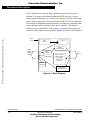
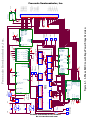
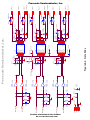
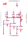
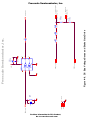
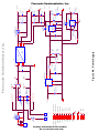
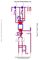
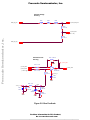
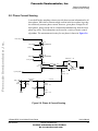
Figure 5-3. Cycle-by-Cycle Current Limiting
User’s Manual
48
3-Phase BLDC Low-Voltage Power Stage
Design Considerations
For More Information On This Product,
Go to: www.freescale.com
MOTOROLA