1
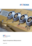
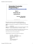
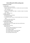
Module for station batteries
diagnostics MDB 201
Operating instructions
2010
Contents
SAFETY INSTRUCTIONS.................................................................................................................................. 2
SPECIAL SYMBOLS............................................................................................................................................... 2
SAFETY INSTRUCTION AND COMMANDS .............................................................................................................. 2
INTRODUCTION................................................................................................................................................. 3
DESCRIPTION..................................................................................................................................................... 4
PARAMETERS..................................................................................................................................................... 5
INSTALLATION .................................................................................................................................................. 6
MECHANICAL MOUNTING .................................................................................................................................... 6
ELECTRICAL WIRING ........................................................................................................................................... 7
SETTINGS............................................................................................................................................................. 9
„SYSTEM SETTINGS REVIEW“ .............................................................................................................................. 9
„SYSTEM SETTINGS“ ........................................................................................................................................... 9
„DISPLAY BACKLIGHT SETTINGS“ ..................................................................................................................... 10
„TIME AND DATE SETTINGS“ ............................................................................................................................. 10
„CAPACITY TEST “............................................................................................................................................. 10
„SERIAL NUMBER“ ............................................................................................................................................ 11
„SERVICE SETTINGS“......................................................................................................................................... 11
„LANGUAGE“ .................................................................................................................................................... 11
DEFAULT SETTINGS....................................................................................................................................... 12
OPERATION ...................................................................................................................................................... 13
MAINTENANCE ................................................................................................................................................ 14
SERVICE AND SERVICE ASSISTANCE....................................................................................................... 15
GUARANTEE TERMS ...................................................................................................................................... 16
1
Safety Instructions
Special symbols
Touching the electrical equipment may be fatal
Warning, read operating instructions
Warning, battery
Do not disposed together with domestic waste
Safety instruction and commands
1. Only authorized and informed person can work on this device
2. Disconnect all wiring before any manipulation
3. Do not unplug any connector under voltage
2
Introduction
The MDB 201 monitor is designed for the protection, monitoring, measurement and
signaling of the operational and failure states of station batteries. Battery protection is
provided mainly due to this protection functions:
•
Disconnection of the charger during an overvoltage on the battery
•
Protection against overcharging the station batteries
•
Protection against improper charging
•
Protection against deep battery discharge
•
Digital recorder of the battery operation
•
Measuring battery current with both polarities, in both the charge and the
discharge phases
•
Performance of orientation capacity test
3
Description
The MDB 201 circuits are designed with the ATMEL 89C52 microprocessor with the
integrated 4.5 digit ICL 7135 A/D converter. The monitor is designed for an industrial
environment; for this reason, it has high operational reliability and safety.
The monitor has no outside power supply; it is supplied from the same potentials as the
measured voltage.
The MDB 101 monitor involves a digital recorder into which the voltage of the station
battery is recorded every hour – memory contents – 3 years. Furthermore, it has the socalled black box into which data are recorded that deviate from the standard operation
(recharging battery OK).
The four-line display with the Czech diacritics is on the front panel. The access to the
monitor values is split into a user and service access. The service access is protected by a
password in order to reduce unprofessional manipulation.
Picture 1 Dimensions MDB 201
4
Parameters
Basics types
Uin
the same as measured
Iin
<50 mA
fin
DC
Unominal
24, 48, 60, 110, 220 V ±25%
Measurement input take-off
10 pA
Display
four-line alphanumeric
Interface
optional
Logical inputs
6
Logical outputs
8 (230 V AC/5 A)
Operational temperature
From 0 to +40 °C
Storage temperature
From -10 to +40 °C
Relative humidity
Dimensions
10 –75%
Weight
Protection
1 kg max
144 x 144 x 144 (155) mm
Front panel IP 40
Rear panel IP 20
Options
Interface
RS485
Table 1 Parameters
5
Installation
Mechanical mounting
The MDB 101 instrument is built into a plastic box designed for mounting into the
switchgear panel. The dimensions of the necessary opening are 139 x 139 mm. Total
thickness of material could be 24mm max.
The device is fixed with two metal threaded clips. The position and installation of upper
clip and is draw on Picture 2. It is necessary to put plastic bolts into clips first and then mount
the monitor into the opening in panel.
Put completed bolts in prefabricated gaps in rear panel then tighten.
Mounting dimension can be seen on Picture 1 and on Chyba! Nenalezen zdroj
odkazů..
Picture 2 Mounting
The device can be mounted in various positions. The temperature of surroundings has
to be in operating temperature range (from 0 °C to +40 °C) otherwise the correct functions of
the device cannot be guaranteed.
6
Electrical wiring
All wires are connected to terminal boxes on rear panel.
Picture 3 Terminal boxes
Picture 4 Connectors wiring
7
Function
X1
X2
X3
Note
1
Supply input
+ UB
2
Supply input
- UB
3
Measurement input
- UB
4
5
6
7
8
Measurement input
Free
Common potencial
Current 1
Current 2
+ UB
shunt X/150 mV
1
Ground connection
+ UB
2
Supply voltage failure
+ UB
3
Supply voltage failure
+ UB
4
Charger failure
+ UB
5
6
Charger failure
Free
+ UB
7
0V
- UB
8
1
2
3
4
5
6
7
8
9
10
11
12
13
14
15
16
0V
Overvoltage
Overvoltage
Overvoltage
Overvoltage
Charging out of range
Charging out of range
Battery is not charged
Battery is not charged
10% capacity left
10% capacity left
External failure
External failure
Under voltage
Under voltage
Under voltage
Under voltage
- UB
break contact
break contact
switch contact
switch contact
switch contact
switch contact
switch contact
switch contact
switch contact
switch contact
switch contact
switch contact
break contact
break contact
switch contact
switch contact
Table 2 Connectors
Terminal boxes are screw-type, for wires up to 2,5 mm2. Indication of input state for
terminals 6 and 7 of terminal box X2 is signaled via green LED. For each pair of terminal box
X3 output the red LED is used. All LEDs are mounted above relevant terminals on rear
panel.
Isolation on connected wires has to be stripped only on needed length of wire. The
bare wires can not be touchable.
Voltage between terminals X1:2 and X1:3 could be 0,7 V maximum.
8
Settings
Entering the control menu with the ENTER button
With the right and left arrows is selected from the items, confirmation is via ENTER
button, arrows are used for set up values, key ESC is used for return.
„System settings review“
This menu is used for review of set values.
„System settings“
This menu is protected by password (2433). Press ENTER, set the code number with
the up and down arrows, validate with ENTER.
„ Calibration “
The measured voltage has to be calibrated with accurate external voltmeter. The
calibration is carried out with the up and down arrows
The voltage has to be calibrated before putting the monitor into work.
„Voltage range settings“
Voltage levels for charging as well as for batteries floating voltage and for signalling
can be set with accuracy 0,1V.
The required value is set with the right and left arrows and the setting is carried out with
the up (+) and down arrows.
These items can be set: overvoltage, charging OK, under voltage, hysteresis (sec).
Observe voltages set by batteries producer.
„Shunt type“
Type of used shunt can be set. The constant is given in
A
. Each shunt is set
mV
individually.
Constants for shunts have to be set before putting the monitor into work.
9
„Date of putting monitor into work“
First putting into operation can be set.
Date of putting equipment into work has to be set.
„Digital recorder of the battery operation“
Recorder of battery voltages values and unusual states is displayed.
„Serial line“
Parameters of serial line could not be set
„Display backlight settings“
Setting up the display backlight, "off" and "on" or “3 minutes” with the right and left
arrows. If “3 minutes” are set display is only backlight only for 3 minutes, the goes off.
„Time and date settings“
There is set value indicated in lower right corner. Can be initiate by pressing F2 as well.
The time and date has to be set before putting the monitor into work
„Capacity test “
Can be initiate by pressing F1 as well.
„last test“
Details about last performed capacity test are recall. Date, measured capacity and
duration of test are measured.
Capacity test is only orientation.
„new test“
First of all, final voltage must be set. Capacity test is finished when battery voltage
drops to set value. Capacity test can be also terminated by maximum time duration of the
test.
Observe voltages set by batteries producer.
10
After setting these parameters is possible to start test. The monitor automatically
disconnects charger and the battery is discharged into load. After finishing the test charger is
connected again a test data are saved in item “last test”
„Serial number“
The version of the device, date of production and serial number are indicated.
„Service settings“
This menu is protected by password (2442)
„Supply voltage“
Nominal voltage is indicated and also switching between version 2,24V/cell and
2,27V/cell is possible in this regime.
Observe voltages set by batteries producer.
„Factory settings“
Default settings are uploaded.
It is highly recommended to not to share passwords with any other persons.
„language“
Can be initiate by pressing F4 as well.
Englisg, German and Czech are available..
11
Default settings
Default settings for MDB
Voltage 2,23V/cell
battery 24V
notice
Overvoltage
Charging with higher voltage
Charging OK
Charging with lower voltage
Battery is not charged
0,95Un/ 10% capacity left
Umin (V)
27,7
27,1
26,4
25,5
21,8
21,1
Umax (V)
27,7
27,1
26,4
25,5
21,8
Under voltage
battery 110V
battery 220V
Umin (V)
Umax (V)
Umin (V)
Umax (V)
124,7
122
118,8
114,8
98,1
95
124,7
122
118,8
114,8
98,1
249,3
243,9
237,6
229,5
196,2
189,9
249,3
243,9
237,6
229,5
196,2
21,1
95
189,9
Default settings for MDB
Voltage 2,27V/cell
battery 24V
notice
Overvoltage
Charging with higher voltage
Charging OK
Charging with lower voltage
Battery is not charged
0,95Un/ 10% capacity left
Under voltage
Umin (V)
28,2
27,5
26,9
26
22,8
21,5
Umax (V)
28,2
27,5
26,9
26
22,8
21,5
12
battery 110V
Umin (V)
126,9
123,8
120,9
116,8
104,5
96,7
battery 220V
Umax (V)
Umin (V)
Umax (V)
126,9
123,8
120,9
116,8
104,5
253,8
247,5
241,9
233,6
199,7
193,3
253,8
247,5
241,9
233,6
199,7
96,7
193,3
Operation
The device do not requested any special treatment and service during operation.
Monitor indicates measured voltage and this measured value is as well commented by
notices:
•
Overvoltage
•
Charging with higher voltage
•
Charging OK
•
Charging with lower voltage
•
Battery is not charged
•
10% capacity left
•
Under voltage
Values for individuals notices can be set via “Voltage range settings”, chapter
“Settings” of this manual.
During fault “Over voltage” output relay is switched on. This relay is switched on until
fault “overvoltage” is confirmed. Status “Overvoltage” is failure with memory. None other
failure has memory.
13
Maintenance
The device does not need any regular maintenance. The regular maintenance
according to valid norms ČSN-EN – electro technical devices has to perform. This
maintenance consists of visual control of the device, cleaning the device (best is via vacuum
cleaner) and of control of proper tighten of screw joints.
This maintenance has to be performed in terms according to status of surroundings,
but maximum 6 months duration.
14
Service and service assistance
In case of queries or problems with the device contact the producer:
PEG spol. s r.o., Baarova 49, 140 00 Prague 4
Plant Kolbenova 922/5a, 190 00 Prague 9
www.peg.cz
[email protected]
Tel: 281 087 521, fax: 281 087 522
GSM
O2: 724 366 435, T-mob: 731 118 119
Please, let us know about these details:
•
Serial number
•
Date of first failure
•
Failure description
15
Guarantee terms
Guarantee for material failure, construction failure and treatment and machining failure
is provided for the devices, duration 24 months. The guarantee could be prolonged only via
contract.
Producer is not responsible for any damage caused by wrong mounting, wrong
operating conditions, settings change or any other conditions which are not in accordance
with documentation. Producer is not responsible for consequences of wrong usage.
Producer of monitor reserves the right to change technical data specification and
details without former notice.
16