1
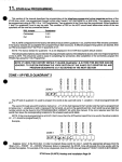
i
SFPOOR
Hook-up & Installation
Fire Burglary
Instruments,
Inc,
SOEngineersRood.Houppouga New York 11788
NEWYORK
l-31 t cnc) LSL1 =
OUTOf STATE
Iann) AUC.C4?0
-.-
REV.8 SEPT 86
l-2257
.
:,
P
.
0
.
.. .
.
exclusively with the XL1218 and XL1219 Control
Panels. incorporating the SFZOOR will enable all on and off-premises telephones (assuming
‘they are touchtone) to be used as keypads. The SFZOOR can be installed on sites which have
rotary or touchtone phones. However, the rotary phones-CANNOT
access the system.
The
rotary
phones
can
only
be
used
to
receive
and
make
standard
phone
calls. XL1218R’
--- and XLI219R keypads-MAY be used-in conjunction with the SFZOOR ii desired,& _
the SFZOOR can be usedbyi?%lfI
If the SFZOOR is used as a stancklone, (with no keypads .-- -.
on site) remote red led terminals have been provided to indicate arm status. To access the
SFZOOR, specific keys must be depressed in specific order via the telephone pad The
SFZOOR will respond clearly with English language messages concerning the system’s status.
languagt messages MUST be programmed into a FBI Model F102
The
..--- SFZOOR
.. .- -- English
prom ctup, as per the, programming se&%--7-.of-&s manual. The
--- SF2OOR
- ..can
-- also be
programmed
to allow off-premises access via^- touchtone telephones.
Lastly,
there
.
.-- ._
are 3 -auxiliary relayswhich contain Form-C Dry C pntacq, that.-can be used to activate onpremzes devices. via the SF200R System. This installation instruction-will
explain
terminal connections of the SFZOOR to the XL12 18 and XL 1219 Control Pan& first,
then
-._.
- proceed with the----prom programming.
I
THE ACTUAL SFZOOR,OPERATION WILL BE EXPLAINED IN THE END USER MANUAL
Tlk
Model
SFZOOR is designed to operate
Keypad Data Terminals.
The SF2OORreadsloop data and insrrum
the Control Panel via these terminals
inals. These wires co
* = These terminals do not have to be connected when the SF2OORis wired to X11218.
l ‘2$ -’
Jt CONTACTS RATED AT ZSVDC, 3AMP:
.
I/
1
-.
.
**
NOTE:
When the Convenience
Switch on the SFtOOR box is depressed, the
home phones will be connected directly to the outside hnes, which
enables the customer to prevent
access to this syncm by on
premises telephones.
However, external access to t.h~s system can still
be accomplrshed.
Furthermore,
the Control Panel will seize the
home phones if a violation occurs. fhis swrtch sno~~normally
be
in the OUT positron.
---w-w-------
SFZOOR
PHONE LINE
TERMINALS
PHONE LINE HOOKUPSF200R
0
;; dx:iOWN
-TO XL1218
. -a. .---------s-m
XL1218
PHONE LINE
TERMINALS
SF2OOR
PHONE LINE
TERMINALS
.
PHONE LINE HOOKUP SF200ReTO-XL1219
,XL1219
PHONE LINE
TERMINALS
::=G31 -
SFZOORP.C.
I
Board.
F-CC. RegbrrmirmNo. A!L398L-6?Ss&M-Ejar FIREBURGLARY WS~RUMENI ~SFxJoR
NOTE: U%cnevatbeS~06Rb
dParmed,itwiU~vtoMtial)ydtlivcrrsfsas
message. li status is not reported an disarm, oepress [*)[*] tvic&
If the
message 7ht CemraJ was nm aJJed. Press Reset” is generated, depress
1~71(01 to reset. Depress [*I I-) AGAIN to 03TAlN FhJ System Sat-,.
AI this porn--- an) other system
functions
desired may be performed.
4PGREEN
RED
.
..
SFZOORPROM PROGRAM
A Prom chip model F102 (DM74S387N, or 63S140N) must be programmed with an FBI 110 or
i IOC programmer for proper operation of the SF200R.Two quadrants of the Prom must be
Programmed. Either quadrants one and two or quadrants three and four may. be us=
The
condition of the R58 resistor jumper in This system will dictate which two quadrants the SFZOOR
will read. The chart below depicts R58 jumper setting for the desired quadrants used.
Quadrants
R58 Jumoer
I Connected
.
l&2
3&S
cut
The main body of programming that ii required for the SFZOOR.is the ENGLISH LANGUAGE
words that will be reported (said) when any, of the zones of the Control Panel are read by
the SFZOOR In .q$er words, the zones Of-. the Control Panel must beeNamed;
‘1 Example: Zone 1 = Front door
Zone 2 = Kitchen
Zone 3 = Basement
-
‘. I
I
I
(THIS INSTRUCtiON B&KLiT
IS I%SIC~Eij TO ACCOMPLISH WRITINCOUT
_
SFZOORPROGRAM SHEET WHICH IS LOCATED ON PAGE’ 12 )
THE
Quadrant 1
STEP’ A
e
The first location of the OP Field, Quad 1, marked Ll must contain a digit
.from the chart below which represents the TYPE of zone that zone 1 has
been programmed in the ‘XL1218 or XL121Vxtrol
Papel.
(example:
24 HR Trouble ‘Zone, 24 HR &arm Zone, Controlled Burglary Zone)
Select the appropriate digit from.chan below:
TRTA;/
The second through eleventh location marked LZ-Lll of this field represent the
5 total words that can be programmed to NAME zone 1. Locations L2 and L3
represent the first word, LO and L5 the second word, etc. Each word desired
has a 2 digit Hexadecimal number that corresponds to that word. The two
digit numbers and corresponding words can be found in the PROGRAMMABLE
LIBRARY, page I&. Write in the appropriate two digit numbers that represent
the words dewed for zone 1 in this OP field. If zone 1 requires less than five
words, leave the corresponding locations for the unused words blank.
NOTEz If zones are programmed as 24 HR. alarm zones, the SF2OOR
will not report the zone words, therefore locations LZ-Lll should
be programmed [FL-
3
cont’d.
pg. 4
-.
._.
$TEP A.
. .
.cont’d.
The following is an example of how the OP field should be programmed
zone 1 is a controlled delay, front door.
if
Since zone 1 is a burglary zone, there are many conditions it could actually
be in during many instances of daily operation. (example: Alarm, Bypass,
Trouble while the system is disarmed, etc.) When status is requested from
the SFZOORthe words that were programmed here into the OP field will
PRECEDE the PHRASES that apply from the DEDICATED LIBRARY of Terms for the
condition of zone & (example:. Zone 1 is bypassea; then siatus is requested.
The SF2OORkill say “FRONT DOOR -& BYPASSED;.- “FRONT DOOR” is from
this OP field, “IS BYPASSED” cob% from the Dedicated Library.)
I
tone 1 has been successfully oroprammed.
STEP B
The 1P field of Quadrant 1 represents zone 2 on the XL1218 and XL1219.
The same procedure must be followed here, as Step A. Ll location reprosents the zone type. Select an appropriate digit from Chart A m Step A.
Location L2-Lll represent the 5 total words to Name zone 2. Select
the 2 digit numbers that CORRESPOND
TO the words desired from the
PROGRAMMABLE LIBRARY.
STEP C
~1.~2
L)
~4
L)
~6.~7
LB
~9llDLI2
The 2P field quadrant .1 represents zone 3 on the XL1218 and XL1219.
the same orocedure
STEP D
Follow
as Steo A.
Quadrant 1
&
,
----2oco
[3l.PI
I
(112
I I I I I I I I I 1
Lf
L&L)
Lb
L7
The 3P field quadrant 1 represents zone 4 of the
as Step A.
the same procedure
LD LQLlOLII--
XLl2i8
and Xil219.
Follow
:
*
CoNTftlL PAa.
. :
STEP E
Quadrant 1
TYPE
‘EXTERNAi’ AC#SS o
RELAY STATUS, EXTERW EXIKR
cl&L
flRE
BELL WTPU7 TYPE
RING COUNT
AC
LLLZ
L3lcr
THE FIRST LOCATION of this AC field marked Ll infor&
the SFZOOR what
Control Panel is being used. Select an appropriate digit from the following
chart for this Ll location.
Digit
Control
0
2
Panel Type
\
XL1218
XL1219
;
.,:
-. ...
-- -’
THE SECOND LOCATION of this AC field marked L2 is used to determine
the following three options:
Option One - External Access: If External Access is programmed, system functions
can be accomplished from off-premises touch-tone
telephones after cdl in.
Option Two - Automatic
Relav Status:
If this option is programmed, wheneverSSYSTEM’
STATUS is requested from the SFZOOR, it mwill include the status of all auxiliary relays. If
“Automatic Relay Status” is not selected,
relay status must be initiatedxnually
by
depressing [#ii] then IS].
Option Three - External Exiter: This option has been included in .the . SFZOOR and :should be used only if the main control instrument (1218 or 1219) has been programmed
to include at least one controlled INTEEIOR----zone.
-..----- The
- purpose of this option is
to-enable the end user-to call from % off-premise telephone, .md arm his system .,
without excluding the interior zone.
When External Exiter is programmed and the system is armed from an OFFPREMISES TELEPHONT, auxiliary relay 3 will automatically a&!?te momentatily. Relay 3 closed circuit contacts 0SF200R terminals- 11 and 12) _ _
MUST be wired in series with the CONTROL PANEL- DELAY LOOP.
Themomentary activation of relay 3, after arming, will ‘simulate exit through the dglay,
zone &sing the control panel to include the interior zone. Relay 3 will not activate :
momentarily when the system is armed from on-premises telephones.
;
Lastly, when this option is selected, relay 3 can no longer be utilized as an auxiliary -1
relay circuit.
l
NOTE: If this option is not selected, relay three will operate the same as auxiliary relay
1 and 2 Select the digit from the following chart which corresponds to all options desired . .
,
DIGIT
EXTERNAL
ACCESS
AUTOMATIC
RELAY
STATUS
1 EXTERNAL EXITER
0
NO
YES
I
NO
3
YES
YES
I
No
YES
I
YES
NO
7
I
8
I
YES
I
NO
I
YES
NO
I
I
NO
B
F
YES
NO
I
YES
I
NO
A
:.’
cont’d..pg.6
5
! “1’.
STEP I
cant ‘d:
THE THIRD LOCATION of this AC field marked L3 informs the SFZOORwhat
type of Fire&11 output has been programmed in the XL1218 or XL1219 Control
Panels. When the SFZOOR system is used in conjunction with the XLI218, the
XL1218 PANEL MUST be programmed PULSING BURG BELL OUTPUT for the Fire
zone. Therefore,
location L3 in the SFZOOR must be programmed with
Dinit [4l when used with the XL1218. The Xl1219 can be oronrammed for
ElftiR- PULSING BURGLARY BELL OUTPUT FOR THE FiRf ZONE OR
STEADY FIRE HORN OUTPUT. Therefore, select a dlglt from the following
Chart wtilu1 informs theSF2OOk what type of Fire output is being- used on
the respective Control Panels.
[
DICK
4
c
I
I
Control
Panel Fire Output
I
Pulsing Burg Bell output for Fire
Steady FJre Horn output
Note: If theSF2OORis used with the XL1218, this 13 location MUST be
programmed Digit [4], AND the XL1218 MUST be programmed
PULSING BURG BELL OUTPUT for the F-one
in Quad 2, 3 P field,
Ll location on ITS Prom.
I
.
,
THE‘ FOURTH LOCATION OFTHIS AC FIELD marked L4 determines the number of rings
required before the SF200Rwill pick up, when accessed from OFF-premises telephones.
Selec; the digit desired from the following chart.
NOTE: If external access has not been selecred, program this location *lFli.
.
DIGIT
I NUMBER OF RINGS
I
3
I
3
4
5
6
II
5
6
7
I
7
4
8
i
9
I
A
.
I
F
j
8
+. 9
10
I
6
No External
Access
I
STEP F
Quadrant
1
The AL field of quadrant 1 represents zone 5 on .the XL1219. The same pr+
cedure must be followed here as Step A to Name *tone 5 of the XL1219. 11
represents the zone type. Select an appropriate dIgIf f.rpm Chart A in Step A.
Locations L2-Lll represent the 5 total words to name zone 5. Select the
2
numbers thar’represent the words desired from the PROGRAMMABLE
LIBRARY.
digit
Note: --Irthe &OOR system is being -used. --in conjunction
AL field MUST be- left- b&k.
.-
STEP G
with the X11218, this
Quadrant 2
The OP field quadrant 2 represents zone 6 of the XL1219. Follow the same
procedure as step F to Name zone 6.
-‘--T-”
Note: If the SFZOORsystem is being used in conjunction witfii’XL12D;-tGs
field MUST be left blank.
STEP H
Quadrant
2
.
The 1P field quadrant 2 is used to N&me auxiliary relay number 1.’
1
Locations Ll-L 10 represent the 5 total words. Select the 2 digit number;
that correspond to the words desired from the PROGRAMMABLE LIBRARY.
The Lll location must be left blank.
Note: If relay 1 is not used, leave this field blank.
. .
-STEP. I
----Aux. Relay 2
1 t 1 1 1 1 1 1 I Ii:
Ll L2 L) La LB L6 I7 La ~9L1OLll
2 represents auxiliary relay 2. The same procedure
01
The 2P field quadrant
must be followed as in Srep H to Name relay 2.
Note: If relay 2 is not used, leave this field blank.
STEP J
Quadrant
2
---r---w-
Aux. Relay 3
The 3P field quadrant 2 represents auxiliary relay 3.The same procedure
be followed as in Step H to Name relay 3.
Note: If relay 3 is not used, leave this field blank.
rnusf
-Note: If External Exirer has been selected in Quad 1, AC Field, 12 Location, thenthis 3P Field, all locations, MUST be programmed “F”.
.
-.
QUADRANT
STEP K
[AlC\
2
--...- . ---.- .--
..__
1 1 1 1 SfClJfiITYJurrrs u)Ix
LI L2 C) 1*
.
This AC Field Quadrant 2 can be used to program 1 through 4 digits (numbers 1-9)
Security access code, beginning in 11 and ending in 14. This code must be utilized when the SFZOORis accessed from OFF-Premises telephones, be=
any
If all locations in this field are programmed
system functions can be accomplished.
“F”, then system functions can be accomplished from OFF-Premises phones without
entering this security access code. However, all system functions that require the
main con=
panel code still apply.
_
-
l
;
STEP 1’
.-
_-
Note:
If (0). is desired in this code; program
NOTE:
This fi$$ qnly. applies if external access
-- _-has
-_ been programmed.
I access has not beefi s&&&d.
or-&ram 11 - Lti *‘r’.
iNote:
I
-.
letter “A” instead.
’
If external
The SFZOOR Program Sheet has been successfully written out at this point.
AU other fields not mentioned in quadrant 1 and 2 must be left blank also.
. (i.e. quad 1 ,AF, FF and Quad 2 FF, AL fields). Utilize the following
informatiorr called Prowr Prom .Proprramming Procedure to actually program
the data written out on the program sheet into the Prom chip.
, Once the Prom chip has been successfully programmed, it must be inserted
into the SFZOOR socket, BLUE DOT UP.
.
~~~
If securitv access
-- code is Dronrammed. the customer must wait
for
the-3?%-OR
fopI&G up ---gftkr the pibgtii&dXirnber
of rings,
,- -.
‘then depress [*] andxs 1 through 4 dlit ws~~-access
co&
‘YhenFeFeed
with
desired
f
unct&s-as
b%plahd
.in’
$&--@d’U_ser
.! _
:Manual.
If the correct ---._.
access code is not entered in 3xits,
the
_
SFZOOR&ill tertiinaie the phone- call.
.8
---’
PROPER PROM PROGRAMMING
PROCEDURE
STEP A
Power up 110 or I IOC. The Prom MUST NOT be in the Programmer at this time.
Insertion of the Prom will be the Ia-epprior
to depressing the Program Button.
STEP B
Select the desired Quadrant to program.
rant (orf of .the chip) at a time.
STEP C
Depress [ENTER] momentarily, then [0] while the programmer socket is empty.
Depressing [ENTER and 0] loads the present contents of the socket into memory.
In the case of an empty socket, memory is loaded wit_h Blanks or [F’s]. A Blank
and an [F] are the same thing. The oniy time the [F] Button must actually be depressed is if one specific location in a Field must be jumoed over to get to another
location to enter a number. Trailing (F’s] at the end of a fieldneed not be depressed
as long as their locations are Blank.
STEP D
Punch in desired information for OP field through AL field in this Quadrant. Movement from OP to the next field and so on, can be accomplished by depressing [ENTER]
then [S]. At the bonom left comer of the programmer resides a chart which represents the field names, descriptions and most important, the field numbers. Jumps can
be accomplished from one field to another by depressing (ENTER], then the respective
field number desired. Example: To jump.from OP ‘field to AC field, depress [ENTER]
then [7]. This variable jumping will become useful for duplicating master chips.
STEP E
After completing data entry into all desired fields, the .Prom may be inserted into
the programmer socket. The Blue Painted dot must be situated down. The Prom
must be pushed all the way in. The programmer does not care what field you are
in when you program. Depress the [Program] Bun~m~entarily,
[Finish] should
be disoiaved.
STEP F
The present quadrant has been successfully programmed. T6 program additional quadrants, the Prom: must be removed, select the desired quadrant and
,
repeat steps C-F.
0
The I10 and 1lOC will program one quad-
Summary:
[F]: The [F] Button does not display anything when depressed, however it jumps’
from one location to the next. The only time the [F] Button must actually be
depressed is when a jump must be made over one location to get to another location where a number must be entered. Trailing FL need not be depressed as long
as their locations are blank.
[Enter], then [O] with socket empty: Loads F’s in selected quadrant.
[Enter], then [0] with Prom in socket: Loads memory with present data that resides in the quadrant selected.
[Enter] then 193: Increments fields from OP to AL back to OP again.
[Enter] then field number: Jumps from one field to another as designated by respective field number.
..
‘-.
,.
-
I.
,
.
r
PROGRAMMABLELIRRARY
.
00
01
02
03
04
05
06
07
08
27 FLOW
28 FOUR
29 FREEZER
2A FRONT
A
AC
AIR CONDITlONER
ALARM
ALL
AND
ARE
AREA
ATTIC
2B GARAGE
2C GUEST
2D HALL
2E HAVE
2F HIGH
09 BACK
04 BASEMENT
CB BATH
Cc BATTERY
OD BE
OE BEDROOM
OF BOILER
10 BURGLAR
11 BYPASSED
12
i3
14
15
16
CALL
CENTRAL
CHECKED
CLOSET
COMPUTER
17 DDD
18 DELAYS
19 DEN
lA.DETECfbR
18 DINING
1C DOOR
1D DOWN
1E
1F
20
21
EAST
EIGHT
ENTRANCE
EXIT
30
31
32
33
34
IMMEDiATELY
IN
INSTANT
INTERIOR
IS
4C PRESSURE
4D PROGRAM
4E PROTECTED
4F
50
51
52
53
READY
RECEIVING
RELAY
RESET
RIGHT
55
ROOM
56
57
58
59
SAFE
SECURITY
SERVICE
SEVEN
5B SIDE
SIX
5D SKYLIGHT
5E SLIDING
5F SMOKE
60 SOUND
61 SOUTH
5c
35 KiTCHEN
.-
.-
36 LAUNDRY
37 LEAVE
38 LEFT
39 LIGHTS
3A LIVING
3B LOW
3C MASTER
3D MEDICAL
3E MUST
62
63
64
SSSSSS
STAIRS
STOCK
65 SYSTEM
66 TEMPERATURE
67 THE
68 THREE
69 TROUBLE
6A- TWO
6B UP
3F NINE
40 NORTH
41 NOT
6C VIOLATED
6D WALL
6E WAS
6F WATER
OFF
44 OFFICE
43
45 ON
46 ONE
47 OUT'
.
.-
22 FACTORY
48 PANIC i
FAN
49
PERIMETER
24 FIRE
4A
POLICE
25, FIVE '
48
PRESS
26 FLOOR
NOT& DDD is to indicate past tense of,a word.
SSSSis to pluralize a word.
70
71
WERE
73
YOU
74
75
ZERO
ZONE
WEST
72 WINDOW
23
-
'
10
.
DEDICATEDLIBRARY
"IS IN ALARM"
"LSIN TROUBLEAND MUST BE CHECKED"
"IS NOT RESET. PRESSRESET"
"IS BYPASSED"
'7HESECURITY COMPUTERISREADY FOR PROGRAM"
'7HESECURITY COMPUTERPROGRAMIS OFF"
"THE SECURITYSYSTEMIS ON"“
"THE SECURITYSYSTEMIS OFF"
'7HE CENTRAL WASNOTCALLED. PRESSRESET"
"ALL SYSTEMDELAYS ARE ON"
"ALL'SYSTEMDELAYS ARE OFF"
e$ "THE ACIS IN TROUBLEAND MUSTBE CHECKED"
%'7HE BATTERYIS IN TROUBLE. CALL-FOR SERVICE"
&'7HE FIRE ZONE IS IN TROUBLE. CALL FOR SERVICE"
"YOU HAVE PRESSEDPANIC
'7HE FIRE SOUNDIS ON"
"THEBURGLARYSOUNDISON"
"IS ON"
"IS OFF'
11