1
SPARCengine™ Ultra™ AXi
OEM Technical Manual
Sun Microsystems, Inc.
901 San Antonio Road
Palo Alto, CA 94303 USA
800-681-8845
Part No. 805-3158-03
May 1999
©1999 Sun Microsystems, Inc. All Rights reserved.
THE INFORMATION CONTAINED IN THIS DOCUMENT IS PROVIDED “AS IS” WITHOUT ANY EXPRESS REPRESENTATIONS OF WARRANTIES. IN ADDITION, SUN
MICROSYSTEMS, INC. DISCLAIMS ALL IMPLIED REPRESENTATIONS AND WARRANTIES, INCLUDING ANY WARRANTY OF MERCHANTABILITY, FITNESS FOR A
PARTICULAR PURPOSE, OR NON-INFRINGEMENT OF THIRD PARTY INTELLECTURAL PROPERTY RIGHTS.
This document contains proprietary information of Sun Microsystems, Inc. or under license from third parties. No part of this document may be reproduced in any form or by
any means or transferred to any third party without the prior written consent of Sun Microsystems, Inc.
Sun, Sun Microsystems, the Sun Logo, SPARCengine, Ultra, Ultra AXi, Solaris, OpenBoot are trademarks or registered trademarks of Sun Microsystems, Inc. in the United States
and other countries. All SPARC trademarks are used under license and are trademarks or registered trademarks of SPARC International, Inc. in the United States and other
countries. Products bearing SPARC trademarks are based upon an architecture developed by Sun Microsystems, Inc.
The information contained in this document is not designed or intended for use in on-line control of aircraft, aircraft navigation or aircraft communications; or in the design,
construction, operation or maintenance of any nuclear facility. Sun disclaims any express or implied warranty of fitness for such uses.
Please
Recycle
Electromagnetic and Safety Information
Compliance with EMI and safety regulations for products including the
SPARCengine Ultra AXi is entirely the responsibility of OEMs. The SPARCengine
Ultra AXi is expected to pass FCC class B tests in a representative enclosure. The
printed wiring boards within the product are manufactured by UL recognized
manufacturers and have a flammability rating of 94-V0 or better.
Note that the product includes a lithium battery, the disposal of which is subject to
regulation in some jurisdictions.
The SPARCengine Ultra AXi is intended for inclusion in systems meeting the
following regulations:
■
■
■
■
USA EMC FCC Class B
USA Safety UL 1950
Canadian EMC IC Class B
Canadian Safety CSA C22.2 No 950
■
European Union EMC CE Mark EN55022 & EN50082-1
European Union Safety CE Mark EN60950
■
Japanese EMC VCCI Class 2
■
Preface
iii
Preface
The SPARCengine Ultra AXi product is a highly integrated, high performance
motherboard designed for the use of OEMs who want to develop products that have
UltraSPARC performance in a PC-ATX environment.
The SPARCengine Ultra AXi OEM Technical Manual describes the functions of the
SPARCengine Ultra AXi motherboard, its controls, indicators, connectors and
pinouts, boot sequence, diagnostics, troubleshooting, installation and removal
procedures, and its specifications. It also provides some of the critical mechanical
drawings for the motherboard and CPU module.
Who Should Use This Book
The SPARCengine Ultra AXi OEM Technical Manual is written for computer
hardware engineers, system programmers, computer technicians and others
involved in the integration of the Ultra AXi motherboard. References are provided
for further details.
How This Book Is Organized
The SPARCengine Ultra AXi OEM Technical Manual is organized as follows:
Chapter 1, “Introduction” explains the capabilities and major features of the Ultra
AXi motherboard.
Chapter 2, “Specification Summary” provides a summary of specifications of the
Ultra AXi motherboard.
iv
SPARCengine Ultra AXi OEM Technical Manual • May 1999
Chapter 3, “Functional Description” provides a short description of the function of
each component on the Ultra AXi motherboard.
Chapter 4, “Sequence of Events at Power Up” details the sequence of events that
occur at Power Up and discusses interaction with OBP and Solaris where applicable.
Appendix A, “Jumpers, Headers, Connectors, and Adapters” describes the jumper
settings, header pinouts, connector pinouts, and adapters on the Ultra AXi
motherboard.
Appendix B, “Mechanical Drawings” provides the drawings for the I/O panel,
CPU module, Ultra AXi motherboard, Creator Graphics module and a thermal map
of the motherboard.
Appendix C, “Assembly, Installation and Initial Start Up Procedures” describes
how to assemble and install a motherboard in a typical ATX-type enclosure and
describes how to install the required software and initially start the system.
Appendix D, “OpenBoot Firmware” provides information on the OpenBoot
Firmware used in the Ultra AXi system.
Appendix E, “System Software Solaris 2.6 Operating Environment” provides
information on the Solaris 2.6 Software used in the Ultra AXi system.
Appendix F, “System Software SunVTS Validation Test Suite” provides
information on the SunVTS suitable for the Ultra AXi system based on SunVTS 2.1
Ultra AXi version.
Related References
System Architecture:
■
■
The SPARC Architecture Manual, Version 9, David L. Weaver and Tom Germond,
editors, PTR Prentice Hall
PCI System Architecture, by Shanley and Anderson, MindShare Press
Specifications and Standards
■ ATX Specification Version 2.01
(http://www.data-tech.co.za/ATX-FORM.htm)
■
PCI Local Bus Specification, Revision 2.1, PCI Special Interest Group, Portland
■
IEEE Standard 1275-1994, Standard For Boot (Initialization, Configuration) Firmware,
Core Practices and Requirements
IEEE Standard 1275.1-1994, Standard For Boot (Initialization, Configuration) Firmware,
ISA Supplement for IEEE P1754 (SPARC)
■
v
■
■
IEEE Standard P1275.6/D4, Standard For Boot (Initialization, Configuration) Firmware,
64 Bit Extensions
PCI Bus Binding to IEEE 1275-1994, Standard for Boot (Initialization, Configuration)
Firmware, Revision 1.0, 14 April 1994, Prepared by the Open Firmware Task Force
of the PCI Alliance
Integrated Circuit Specifications:
■ UltraSPARC IIi User’s Manual
(805-0087-01)
■ SME1040 Highly Integrated 64-bit RISC Processor, PCI Interface Data Sheet
(805-0086-02)
■ STP2003QFP PCI Input Output Controller (PCIO) User’s Manual
(802-7837-01)
■ STP2210QFP Reset/Interrupt/Clock Controller (RIC) User’s Manual
(805-0167-01)
■ SME2411BGA-66 Advanced PCI Bridge (APB) User’s Manual
(805-1251-01)
Other Sun Publications
■ Open Boot 3.X Command Reference Manual
(802-5837-10)
■ Open Boot 3.X Command Supplement for PCI (Solaris 2.5.1, 8/97)
(805-1627-10)
■ Writing Fcode 3.x Programs
(802-6287-10)
■ ASM Utilization and Calibration Application Note
(805-4877-01)
■ Sun VTS 2.1 Users Guide
(802-7299-10)
■ SunVTS 2.1 Test Reference Manual
(802-7300-10)
vi
SPARCengine Ultra AXi OEM Technical Manual • May 1999
What Typographic Changes Mean
The following table describes the typographic changes used in this book.
TABLE P-1
Typographic Conventions
Typeface or
Symbol
Meaning
Example
AaBbCc123
The names of commands, files,
and directories; on-screen
computer output
Edit your .login file.
Use ls -a to list all files.
machine_name% You have mail.
AaBbCc123
What you type, contrasted with
on-screen computer output
AaBbCc123
Command-line placeholder:
replace with a real name or
value
To delete a file, type rm filename.
AaBbCc123
Book titles, new words or
terms, or words to be
emphasized
Read Chapter 6 in User’s Guide. These
are called class options.
You must be root to do this.
machine_name% su
Password:
Prompts in Command Examples
The following table shows the default system prompt and superuser prompt for the
C shell, Bourne shell, and Korn shell and OBP.
TABLE P-2
Prompts
Shell
Prompt
C shell prompt
machine_name%
C shell superuser prompt
machine_name#
Bourne shell and Korn shell
prompt
$
Bourne shell and Korn shell
superuser prompt
#
OBP Prompt
ok
vii
viii
SPARCengine Ultra AXi OEM Technical Manual • May 1999
Contents
1.
2.
Introduction
1-1
1.1
Features
1-3
1.2
Determination of Serial Number and Version
1.2.1
Motherboard
1-5
1.2.2
CPU Module
1-6
1.2.3
Firmware
1.2.4
Software
1-6
1-6
1.3
Technical Support and Warranty
1.4
Independent Hardware Vendors (IHV)
1.5
Version History
1-7
1-7
1-8
1.5.1
Ultra AXi Board
1.5.2
CPU Module
1.5.3
OBP
1.5.4
Solaris
1-8
1-8
1-9
1-9
Specification Summary
2.1
1-5
2-1
Functional Specifications
2-1
2.1.1
CPU Module
2-2
2.1.2
Main Memory Modules
2.1.3
UPA64S Interface (Optional FFB)
2.1.4
Ultra-Wide SCSI Interface (SYM53C876)
2-2
2-3
2-4
Contents
ix
3.
Contents
Ethernet 10/100 BASE-T Interface
2.1.6
PCI Connectors
2.1.7
Sun Keyboard and Mouse Interface
2.1.8
PS/2 Keyboard Interface
2.1.9
PS/2 Mouse Interface
2-6
2.1.10
Parallel Port Interface
2-6
2.1.11
Serial Port Interface
2.1.12
Floppy Disk Drive Interface
2.1.13
Non-Volatile Memory, Time-of-Day
2.1.14
Advanced System Monitoring
2.1.15
Default Power On/Off Jumper
2.1.16
Power On-Off Switch (front of enclosure)
2.1.17
Speaker (enclosure mounted)
2.1.18
Reset Switch (front of enclosure)
2.2
Power Requirements
2.3
Mechanical
2.4
Reliability
2.5
Environmental
2.6
EMI Compliance
2-15
2.7
U.L. Recognition
2-15
2-5
2-5
2-7
2-7
2-11
2-12
2-12
2-14
2-14
3-1
3-1
3.1.1
Terminology
3-2
3.1.2
Block Diagram
3-3
3.2
Layout Diagram
3.3
SPARCengine Ultra AXi Motherboard
3-4
3.3.1
CPU Module
3-5
3.3.2
Main Memory Modules
3.3.3
Flash Memory
3-6
3-5
2-8
2-8
2-13
General Information
2-6
2-6
2-13
Functional Description
3.1
x
2.1.5
3-5
2-12
3.4
3.5
4.
3.3.4
TOD/NVRAM
3-6
3.3.5
FFB2 Graphics
3-6
3.3.6
Communication Ports
3.3.7
Printer Port
3.3.8
Sun Keyboard and Mouse
3.3.9
PS/2 Keyboard and Mouse
3.3.10
Floppy Drive
3-8
3.3.11
Ethernet Port
3-8
3.3.12
External and Internal SCSI Interface
3.3.13
PCI Bus Connectors
3.3.14
Memory Bus
3-9
3.3.15
UPA64S Bus
3-9
3.3.16
PCI 66 Bus
3.3.17
EBus2
3-6
3-7
3-7
3-7
3-8
3-9
3-9
Advanced System Monitoring (ASM)
3-9
3.4.1
Temperature Monitoring Points
3.4.2
Voltage Monitoring Nodes
3.4.3
Fan Control and Monitoring
3.4.4
OBP Functions for ASM
3.4.5
Solaris Driver Functions for ASM
Miscellaneous Information
Sequence of Events at Power Up
4.1
Configuration
4.2
Reset Cautions
Jumpers
A-3
A.2
Headers
A-4
3-10
3-10
3-10
3-11
3-11
3-12
4-1
4-1
4-3
A. Jumpers, Headers, Connectors, and Adapters
A.1
3-8
A.2.1
Reset Switch Header J1501
A.2.2
Power On LED Header J1990
A-1
A-4
A-5
Contents
xi
A.3
A.2.3
PS/2 Mouse Header J2500
A.2.4
PS/2 Keyboard Header J2501
A.2.5
PS/2 Speaker Header J3201
A.2.6
Power On-Off Switch Header J3301
A.2.7
Reserved (Do Not Use)J3302
A.2.8
12V Optional/Back Fan HeaderJ3602
A.2.9
12V CPU/Front Fan HeaderJ3603
Connectors
A-5
A-5
A-6
A-6
A-6
A-7
A-7
A-8
A.3.1
ATX Power Connector J1901
A-8
A.3.2
Memory DIMMs J0301, J0302, J0303, J0304
J0401, J0402, J0403, J0404 A-9
A.3.3
UltraSPARC Module (Memory and UPA64S)
ConnectorJ0101 A-10
A.3.4
UltraSPARC Module (PCI-66) ConnectorJ0102
A.3.5
UPA64S (Vertical FFB) ConnectorJ0601
A.3.6
PCI 32-Bit Connectors J2001, J2002, J2003
J2101, J2102, J2103 A-18
A.3.7
Internal SCSI ConnectorJ1001
A-19
A.3.8
External SCSI ConnectorJ1003
A-20
A.3.9
Floppy Disk Drive Connector J1902
A.3.10 Serial Port Male Connector J1802
A-15
A-21
A-22
A.3.11 Parallel Port Female Connector J0901
A-23
A.3.12 EtherNet Transceiver Connector TPJ2301
A.3.13 Sun Keyboard and Mouse J0902
A.4
Adapters
A-26
A.4.1
(PS/2) Keyboard and MouseJ2500 Mouse
AdapterJ2501 Keyboard A-26
A.4.2
Serial Port Channels A and B
B. Mechanical Drawings
xii
Contents
A-25
A-27
B-1
B.1
Ultra AXi Motherboard Dimensions
B.2
Height Profiles
B-3
B-1
A-24
A-13
B.3
Back Panel Connections
B-6
B.4
Thermal Map
B.5
UltraSPARC IIi CPU Module Mechanical Drawings
B-7
C. Assembly, Installation and Initial Start Up Procedures
C.1
C.2
Before You Start
Materials Required
C.1.2
Power Budgeting
C.1.3
Software Installation Information
C.1.4
Tools Required
Typical Assembly
C-2
C-3
C-5
C-5
C.3
Initial Power-On and Firmware Update
C.4
Software Installation
C.5
System Aging Test
C-16
C-26
C-27
C-28
D-1
D.1
Minimum Requirements
D.2
Additional OBP Features in Ultra AXi
D-2
D-2
D.2.1
Additional Commands
D-3
D.2.2
Additional Environment Variables
D.3
Flash Memory and NVRAM Layout
D.4
Power on Self-Test (POST)
D.5
OpenBoot Diagnostics (OB Diag)
D.6
Entering the OBP Environment
D.7
Selected OBP Commands
D.8
Configuration Variables
D.9
Device Tree
D-3
D-4
D-5
D-6
D-7
D-8
D-9
D-11
D.10 PCI Probe Lists
D.11
C-4
DIMM Configuration Considerations
D. OpenBoot Firmware
C-1
C-1
C.1.1
C.2.1
B-9
Device Aliases
D-12
D-13
D.12 OBP Video Drivers
D-14
Contents
xiii
D.12.1 Sun FFB Video Drivers
D.12.2 PCI Video Drivers
D.13 PS/2 Keyboard
D-15
D.14 ASM Operation
D-16
D.15 Field Upgrade of OBP
D-14
D-15
D-16
D.15.1 Upgrading OBP When Operating in OBP
D.15.2 Upgrading OBP When Operating in OS
E. System Software
Solaris 2.6 Operating Environment
E.1
Software Package
E.1.1
Publications
E.3
Installation
E.4
System Requirements
E.5
Ultra AXi Platform Specifics
E-2
E-2
E-2
Advanced System Monitoring (ASM)
E.5.2
Video Drivers
E.5.3
Set the Display Mode for OpenWindows or CDE
E.5.4
PS/2 Keyboard Key Mapping
E.5.5
PS/2 Mouse
E.5.6
Speaker
Contents
E-3
E-4
E-7
E-8
E-9
Adding PCI Cards and Drivers
E-9
E.6.1
To Install a PCI Card
E.6.2
To Verify the Board is Seen by the System
E.6.3
To Obtain Additional Assistance
Language Versions
Distribution
F.1.1
xiv
E-3
E.5.1
E-10
E-10
E-10
E-11
F. System Software
SunVTS Validation Test Suite
F.1
E-1
E-2
Technical Support
E.7
D-18
E-1
E.2
E.6
D-17
F-1
F-1
Obtaining Documentation from the Web
F-2
E-5
F.2
System Requirements
F-2
F.3
Installing SunVTS
F.4
Configuring and Running SunVTS
F.5
Error Messages
F.6
Ultra AXi Specific Implementation
F.7
SunVTS Test Reference Manual Table of Contents
F.8
Loopback Connectors
F-2
F-3
F-3
F-4
F-4
F-6
Contents
xv
xvi
Contents
Figures
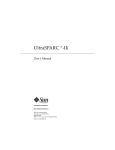
FIGURE 1-1
Possible Configuration Examples
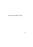
FIGURE 1-2
SPARCengine Ultra AXi Motherboard 1-4
FIGURE 1-3
Motherboard Serial Number, Version Number and Date Code Locations 1-5
FIGURE 1-4
CPU Module Serial Number and Date Code Locations 1-6
FIGURE 3-1
Ultra AXi Motherboard Block Diagram
FIGURE 3-2
Ultra AXi Layout 3-4
FIGURE A-1
Ultra AXi Jumper, Header, and Connector Layout A-2
FIGURE B-1
Ultra AXi Motherboard IO View
FIGURE B-2
Ultra AXi Motherboard Top View B-2
FIGURE B-3
Height Profile Top View B-3
FIGURE B-4
Height Profile IO Side of Board (No CPU Fan)
FIGURE B-5
Height Profile from Module End of Board (No CPU Fan)
FIGURE B-6
Height Profile IO Side of Board (with CPU Fan)
FIGURE B-7
Height Profile from Module End of Board (with CPU Fan)
FIGURE B-8
IO Panel of the Ultra AXi Motherboard
FIGURE B-9
Ultra AXi Motherboard Thermal Map B-7
FIGURE B-10
UltraSPARC IIi Straight Fin Heatsink Module (360 MHz and above)
FIGURE B-11
UltraSPARC IIi Pin Fin Heatsink Module (360 MHz, 333 MHz, and 300 MHz)
1-2
3-3
B-1
B-4
B-4
B-5
B-5
B-6
B-9
B-10
Figures
xvii
FIGURE B-12
UltraSPARC IIi Pin Fin Heatsink Module (270 MHz)
FIGURE B-13
UltraSPARC IIi Module With Pin Fin Heatsink
FIGURE C-1
Ultra AXi IO Panel
FIGURE C-2
Ultra AXi Motherboard Installation C-6
FIGURE C-3
UltraSPARC IIi Module C-6
FIGURE C-4
UltraSPARC-IIi CPU Module Insertion C-7
FIGURE C-5
Hold-down Installation for CPU Module with Pin Fin Heatsink
FIGURE C-6
Hold-down Installation for CPU Module with Straight Fin Heat Sink C-9
FIGURE C-7
Hooking Up the CPU Fan Power Supply Wires to the J3603 Header
FIGURE C-8
Ultra AXi PS/2 Keyboard and Mouse Adapter
FIGURE C-9
IO Panel Connector Panel Fasteners
FIGURE C-10
Ultra AXi Hard Drive Installation C-12
FIGURE C-11
Ultra AXi Floppy Drive Installation
FIGURE C-12
Ultra AXi CD ROM Drive Installation C-14
FIGURE C-13
Ultra AXi DIMM Installation C-15
FIGURE C-14
DIMM Sockets Pair Assignments C-17
FIGURE C-15
Motherboard Power Connection C-21
FIGURE C-16
Floppy Drive Motherboard Connection C-21
FIGURE C-17
Internal SCSI Connector C-22
FIGURE C-18
Power On-Off Header C-23
FIGURE C-19
Power On LED Header C-23
FIGURE C-20
Speaker Header
FIGURE C-21
Reset Switch header C-24
FIGURE C-22
Optional Fan Power Cable Motherboard Header (if available) C-24
FIGURE C-23
Optional Fan Power Cable Motherboard Header
FIGURE C-24
ATI Video Boost PCI Card C-25
FIGURE D-1
OpenBoot Firmware Block Diagram D-1
B-11
B-12
C-5
C-8
C-10
C-11
C-11
C-13
C-23
C-24
Figures
xviii
FIGURE D-2
Ultra AXi CPU PROM Content Layout
FIGURE D-3
Ultra AXi NVRAM Content Layout
D-4
D-5
Figures
xix
xx
Figures
Tables
TABLE 2-1
CPU Module Options
TABLE 2-2
DC-to-DC Converter Core Voltage Output 2-11
TABLE 3-1
Determining Input and Output Devices at Power-up
TABLE 4-1
Power Up Sequence
TABLE A-1
Motherboard Jumper Settings
TABLE A-2
Header Summary
TABLE A-3
Reset Switch Header
TABLE A-4
Power-On LED Header
TABLE A-5
PS/2 Mouse Headers
TABLE A-6
PS/2 Keyboard Header
TABLE A-7
PS/2 Speaker Header
TABLE A-8
Power Enable Switch Header
TABLE A-9
Reserved Header A-6
TABLE A-10
12V Back Fan Header A-7
TABLE A-11
12V CPU Fan Header A-7
TABLE A-12
ATX Power Connector
TABLE A-13
Memory DIMMs Pinouts
TABLE A-14
UltraSPARC Module (Memory/UPA64S) Connector
TABLE A-15
PCI 66 Connector Pinouts
2-2
3-12
4-2
A-3
A-4
A-4
A-5
A-5
A-5
A-6
A-6
A-8
A-9
A-10
A-13
Tables
xix
TABLE A-16
UPA64S (Vertical FFB) Connector Pinouts
TABLE A-17
32-Bit PCI Connector Pinouts
TABLE A-18
SCSI Internal Connector (Channel A) Pinouts
TABLE A-19
SCSI External Connector (Channel B) Pinouts
TABLE A-20
Floppy Connector
TABLE A-21
DB-25 Serial Port Male Connector Pinouts
TABLE A-22
Parallel Port Connector Pinouts
TABLE A-23
Type RJ-45 Connector
TABLE A-24
Sun Keyboard/Mouse Connector Pinouts
TABLE A-25
PS/2 Mouse Connections
TABLE A-26
PS/2 Keyboard Connections
TABLE A-27
25-Pin Serial Channel A and B Connectors (Y Cable)
TABLE B-1
Maximum Case Temperatures for Motherboard “Hot Spot” Components
TABLE C-1
Materials Required (May be duplicated and used to record materials used) C-2
TABLE C-2
System and Peripheral Power Budgeting Requirements Table
(Duplicate and use as worksheet to budget for a specific configuration)
A-15
A-18
A-19
A-20
A-21
A-22
A-23
A-24
A-25
A-26
A-26
A-27
TABLE C-3
Installation Information Work Sheet
(May be Duplicated and Used to Record Build Data) C-4
TABLE C-4
DIMM Configurations
TABLE C-5
Acceptable DIMM Locations 10-bit Column Address Mode C-20
TABLE C-6
Acceptable DIMM Locations 11-bit Column Address Mode C-20
TABLE D-1
Commonly Used Commands D-8
TABLE D-2
NVRAM Configuration Variables
TABLE E-1
Default Sun to PS/2 Equivalent Keystrokes
TABLE E-2
Equivalent Sun and PS/2 Mouse Buttons E-9
TABLE F-1
SunVTS Release Summary F-1
TABLE F-2
SunVTS Test Reference Manual Chapter Applicability
B-8
C-3
C-18
D-9
E-7
F-4
Tables
xx
CHAPTER
1
Introduction
The SPARCengine Ultra AXi is one of the latest members of Sun’s PCI-based
platform family. The Ultra AXi motherboard conforms to the ATX form factor,
supports six PCI expansion slots, and is designed to use industry standard
peripheral devices. SPARC architecture allows direct execution of Solaris operating
environment in native mode, with CPU speeds up to 440 MHz and the capability to
upgrade to faster processors as they become available. The SPARCengine Ultra AXi
motherboard makes it possible to build a general purpose computer using the
Solaris operating environment in a simple, modular assembly. Powered by the
UltraSPARC IIi processor, the Ultra AXi is designed to meet critical, high demand
application needs.
The Ultra AXi motherboard is intended for use in reliable, high performance
applications. The Ultra AXi uses the UltraSPARC IIi processor. The design objectives
include:
■
■
■
■
■
The basis for building robust general purpose computing platforms for
communications, networking or imaging
Complete I/O subsystem: Ethernet, keyboard, mouse, serial ports, parallel port,
disk drives and floppy disk
Industry standard components
Industry standard expansion: six 32-bit PCI slots
Industry standard DRAM DIMMs, monitor, enclosure, and power supply
1-1
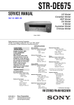
Enclosure
PSU
HDD
UltraSPARC IIi CPU Module
Cables
CDROM
Floppy
Adapters
Solaris 2.6
CD
DOCUMENTS
Memory DIMMs
Ultra AXi Motherboard
System Integration
Solaris 2.6
FIGURE 1-1
1-2
Possible Configuration Examples
SPARCengine Ultra AXi OEM Technical Manual • May 1999
1.1
Features
■
■
■
■
■
■
■
■
■
■
■
■
■
■
Complies with ATX Specification and can utilize a wide variety of standard
enclosures
Operates under Solaris 2.6 HW 3/98 and later (Solaris 7 recommended)
Uses UltraSPARC IIi 270 MHz, 300 MHz, 333 MHz, and 360 MHz processors
Supports up to 1GB memory on-board (32MB minimum)
PCI Local Bus master/slave interface
Autosensed 10BASE-T (802.3) or 100BASE-T (802.30) Ethernet, with fully-buffered
transmit and receive channels
Two Ultra-Wide SCSI buses, one internal, one external
Floppy drive interface
Parallel port, P1284-compliant, with ECP and EPP
Two high speed serial ports
Interface for Sun keyboard and mouse and PS/2 keyboard and mouse
NVRAM/Real Time Clock module
Flash EPROM
Creator Graphics Module supported
Chapter 1
Introduction
1-3
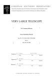
FIGURE 1-2
1-4
SPARCengine Ultra AXi Motherboard
SPARCengine Ultra AXi OEM Technical Manual • May 1999
1.2
Determination of Serial Number and
Version
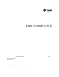
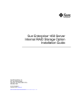
1.2.1
Motherboard
The Ultra AXi Motherboard serial number, version number and date code can be
found on stickers located next to the internal SCSI connector (J1001). See
FIGURE 1-3, following and FIGURE 3-2 on page 3-4. The version number typically
appears as “-05 Rev.50”. The date code “0798” would mean the board was assembled
in the seventh week of 1998.
S501459900054
BAR CODE
Serial number
Version
FIGURE 1-3
-05 Rev 50 CEL 0798
ASSEMBLED IN CANADA
Date code
Motherboard Serial Number, Version Number and Date Code Locations
Chapter 1
Introduction
1-5
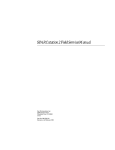
1.2.2
CPU Module
The UltraSPARC IIi module Part Number and Serial Number can be found on a
sticker located on the side of the 180 pin module connector (J0101) facing the PCI
expansion slots. See FIGURE 1-4, following and FIGURE C-5 on page C-8.
Date Code
Serial Number
5015040000145
BAR CODE
FIGURE 1-4
1.2.3
5040 - 02
REV 01
0998
ASSEMBLED IN CANADA
CPU Module Serial Number and Date Code Locations
Firmware
To determine which version of OBP is installed, enter the appropriate command:
If running OBP, at the OK prompt type:
ok> .version<cr>
The system will display:
OBP 3.10.X <creation date>
POST 2.Y.0 <creation date>
If running Solaris, at the <machine_name> prompt type:
<machine_name> /usr/sbin/prtconf -V
The system will display:
OBP 3.10.X <creation date>
The third character group (X) in OBP is the revision number.
1.2.4
Software
To determine the release number of Solaris, at the <machine_name prompt> type:
<machine_name> uname -r
The machine will display the OS version in the following format:
X.X.X
1-6
SPARCengine Ultra AXi OEM Technical Manual • May 1999
1.3
Technical Support and Warranty
Should you have any technical questions or issues that are not addressed in the
SPARCengine Ultra AXi OEM Manual or on the Web site, contact your local
SunService Solution Center. To contact SunService in the U.S., phone (800) USA4SUN (800-872-4786). To find the SunService Worldwide Solution Center nearest you
go to this URL:
http://www.sun.com/service/contacting/solution.html
When you call SunService, be sure to indicate that the motherboard and CPU
module was purchased separately and is not associated with a system. Identify the
product by its part number.
■
■
■
■
■
■
■
SPARCengine Ultra AXi Motherboard — 501-4559-xx
UltraSPARC-IIi 270 MHz Module — 501-5039-xx
UltraSPARC-IIi 300 MHz Module — 501-5040-xx
UltraSPARC-IIi 333 MHz Module — 501-5090-xx
UltraSPARC-IIi 360 MHz Module — 501-5222-xx
UltraSPARC-IIi 360 MHz Module — 501-5148-xx
UltraSPARC-IIi 440 MHz Module — 501-5149-xx
The SPARCengine Ultra AXi includes a 1-year return-to-depot warranty. Should
your board fail during this period, contact your local SunService representative for
instructions. Before you call, get the motherboard date code (for example, 0798 for
the seventh week of 1998) and serial number from the stickers located next to the
internal SCSI connector (J1001). The module date code and serial number are on
stickers on the 180 pin connector of the module. See FIGURE 1-3 on page 1-5 and
FIGURE 1-4 on page 1-6 for a detailed illustration.
1.4
Independent Hardware Vendors (IHV)
Independent Hardware Vendors generally supply non-Sun parts, components and
peripherals such as PCI and graphics cards, enclosures, power supplies, memory,
hard disk drives, floppy disk drives, CD-ROM drives, monitors, keyboards, mouse
devices, cables and adapters.
A list of these IHVs can be found on the Internet at:
http://www.sun.com/microelectronics/ihv
Chapter 1
Introduction
1-7
1.5
Version History
This section summarizes the version history of the Ultra AXi board, CPU modules,
OBP, and Solaris operating environment.
1.5.1
Ultra AXi Board
There are four versions of the Ultra AXi board:
1.5.2
■
-04 — The initial release of the Ultra AXi board (March 1998)
■
-05 — Upgrade to OBP 3.10.7 (November 1998)
■
-06 — Fabrication rework to improve manufacturability (March 1999)
■
-08 — The latest release of the Ultra AXi board (April 1999), which added the
J3303 jumper to specify the power on/off default (see Section 2.1.15 “Default
Power On/Off Jumper” on page 2-11 for a functional description) and upgraded
to OBP 3.10.8.
CPU Module
There are five versions of the CPU module. These are supplied with the Ultra AXi
board when the Ultra AXi board is ordered. These modules can also be ordered
separately to upgrade an existing Ultra AXi board (see Section 2.1.1 “CPU Module”
on page 2-2 for more information about the available CPU module choices).
■
270 MHz CPU — UltraSPARC-IIi 270 MHz module (501-5039-xx)
■
300 MHz CPU — UltraSPARC-IIi 300 MHz module (501-5040-xx)
■
333 MHz CPU — UltraSPARC-IIi 333 MHz module (501-5090-xx)
■
360 MHz CPU — UltraSPARC-IIi 360 MHz module (501-5222-xx)
■
360 MHz CPU — UltraSPARC-IIi 360 MHz module (501-5148-xx)
■
440 MHz CPU — UltraSPARC-IIi 440 MHz module (501-5149-xx)
Faster CPU modules will be supported as they become available.
1-8
SPARCengine Ultra AXi OEM Technical Manual • May 1999
1.5.3
OBP
The OBP is an integral part of the Ultra AXi board. The OBP can also be field
upgraded, with the binaries distributed over the SunWeb (refer to Section D.15
“Field Upgrade of OBP” on page D-16 for information on how to do this).
■
OBP 3.10.4 — The initial release for the Ultra AXi board (March 1998)
■
OBP 3.10.6 — Upgrade in April 1998, which fixed minor bugs and added support
for additional video graphics cards
■
OBP 3.10.7 — Upgrade in November 1998, which fixed minor bugs and added
miscellaneous enhancements
■
OBP 3.10.8 — Upgrade in April 1999, which added support for the UltraSPARCIIi 360 MHz module (501-5148-xx) and UltraSPARC-IIi 440 MHz module (5015149-xx)
An OBP upgrade will be required to support faster CPU modules as they become
available.
1.5.4
Solaris
The SPARC Platform version of Solaris is distributed through SunExpress.
■
Solaris 2.6 3/98 — The initial release for the Ultra AXi board
■
Solaris 2.6 5/98 — The next upgrade for the Ultra AXi board
■
Solaris 2.7 (Solaris 7) — The latest release for the Ultra AXi board
Chapter 1
Introduction
1-9
1-10
SPARCengine Ultra AXi OEM Technical Manual • May 1999
CHAPTER
2
Specification Summary
2.1
Functional Specifications
These specifications describe the Ultra AXi motherboard and the applicable version
of the OpenBoot Firmware and Solaris. (Solaris must be purchased separately.)
2-1
2.1.1
CPU Module
TABLE 2-1
CPU Module Options
Choice 1
(270 MHz)
Description
CPU module
features
Choice 2
(300 MHz)
Choice 3
(333 MHz)
Choice 4
(360 MHz)
Choice 5
(360 MHz)
Choice 6
(440 MHz)
Compliant with V9 SPARC architecture specification,
extended VIS support, integrated E-Cache support,
integrated interface similar to PCI Rev. 2.1
CPU Module
(packaged
separately)
Processor speed
Part No.
Cache
UltraSPARC
IIi-270
UltraSPARC
IIi-300
UltraSPARC
IIi-333
UltraSPARC
IIi-360
UltraSPARC
IIi-360R
UltraSPARC
IIi-440R
270 MHz
300 MHz
333 MHz
360 MHz
360 MHz
440 MHz
501-5039-03
501-5040-03
501-5090-01
501-5222-01
501-5148-02
501-5149-04
256 KB
512 KB
2 MB
2 MB
256 KB
2 MB
Power requirement
See TABLE C-2 on page C-3
Core voltage used
See TABLE 2-2 on page -11
CPU Module Board
dimensions
4 inches (101.6 mm) x 5 inches (127 mm)
1.65 inches (41.9 mm) in height
Interface connectors
Maximum heat sink
temperature[1]
2.8 inches (71.12 mm) in
height[2]
120-pin, 180-pin
See A.3.3 on page A-10 and A.3.4 on page A-13
93oC
Air flow
requirement
92oC
91oC
90oC
300 lfm. (91.5 M/min.) on the heatsink
75oC
73oC
Sun-supplied CPU fan
required[3]
1. The maximum heat sink temperature was measured by gluing a thermal couple in a #60 hole in the heat sink located in the center of
the CPU area. The thermal couple was flush with the bottom of the heat sink.
2. Includes height of the CPU fan that is part of the CPU module hold-down bracket (see FIGURE C-6 on page C-9 for an illustration).
3. The typical heat sink temperature is less than 12oC above the inlet temperature when the CPU fan is running at maximum speed.
2.1.2
2-2
Main Memory Modules
Min. required memory
32MB
Max. supported memory
1GB
8 sockets provided (4 Pairs)
Access size
128 DATA bits + 16 ECC bits = 144 bits = 1 Pair
1 Pair = 2 sockets of 72 + 72 bits DIMM
SPARCengine Ultra AXi OEM Technical Manual • May 1999
Sockets for memory
8 sockets, 2 min. populated with DIMMs of identical
capacity. Pairs of different size auto configured, accepted
DIMM modules
DRAM, EDO, Inputs Buffered except RAS,
3.3V, 60nS, 72bits, 168 Pins
10-bit column address up to 128 MB
11-bit column address up to 128 MB
Caution – Use 60 ns DIMMs only on the Ultra AXi motherboard.
Refresh Rate
CAS before RAS, 2K rows refreshed in 32 ms, (15.5 µs)
ECC features
Single bit error correction
Double bit error detection
Height
Enclosure restriction may apply
Note – Some standard ATX chassis have height restrictions
2.1.3
Width
The connectors are 0.297 inches (7.544 mm.) wide.
A module thicker than this will partially block the
adjacent connector
Other References
See A.3.2 on page A-9, TABLE C-4 on page C-18 and
TABLE C-5 on page C-20
UPA64S Interface (Optional FFB)
SunExpress Part Number
X3663A
Interface connector
UPA64S, J0601, see A.3.5 on page A-15
Functional specification
Refer to Data sheet PN 270-4172-02
Monitor supported
Sun Monitor, 13W3 connector
Note – The optional FFB card will block access to one PCI slot.
Chapter 2
Specification Summary
2-3
2.1.4
Ultra-Wide SCSI Interface (SYM53C876)
Interface connector
68-pin UW connector rear panel for external devices
68-pin UW connector J1001 for internal devices
See A.3.7 on page A-19 and A.3.8 on page A-20 for
pinouts and part numbers
No. of devices
Up to 8 devices on internal SCSI interface
Up to 8 devices on external SCSI interface
(The SCSI controller is considered one device)
Modes of operation
Both narrow 8-bit and wide 16-bit in DMA modes are
supported
Electrical interface
Single ended, fast-20, 16-bit wide bus
Cable length
Max.
Max.
Max.
Max.
Max.
Max.
Max.
Cable termination
Required for both ends of internal and external cables
OnBoard termination always active for internal
OnBoard termination always active for external
Last device on cable end needs to be terminated
3 Meters for 2 devices (2 connectors)
3 Meters for 3 devices (3 connectors)
3 Meters for 4 devices (4 connectors)
3 Meters for 5 devices (5 connectors)
1.5 Meters for 6 devices (6 connectors)
1.5 Meters for 7 devices (7 connectors)
1.5 Meters for 8 devices (8 connectors)
SCSI ID selection (Solaris default settings, internal SCSI bus)
OnBoard controller: 7
CD-ROM: 6
Hard Disk 1: 0
Hard Disk 2: 1
Boot Support
Solaris CD-ROM: Single user, install operations
Solaris installed hard disk: single user, multi user, all
operations
SCSI Devices Supported
CD-ROM drive with (512Bytes block size for bootable)
Hard disk drives
Tape drive units
Other devices need suitable Solaris device drivers
Additional SCSI information can be found at the
following URL: http://scitexdv.com:8080/SCSI2/
Frames/SCSI2.html
2-4
SPARCengine Ultra AXi OEM Technical Manual • May 1999
2.1.5
2.1.6
Ethernet 10/100 BASE-T Interface
Interface Connector
RJ-45, 8-pin connector
Bootable via Network
Data Bit rate
10BASE-T @ 10Mbits/sec
100 BASE-T @ 100Mbits/sec
IEEE 802.3u Auto Negotiation
External Cables
Category 3, 4 or 5 unshielded twisted pair cable,
1000 Meter max for 10BASE-T operation
Category 5 unshielded twisted pair cable,
100 Meter max for 100BASE-T operation
PCI Connectors
Compatibility
Compliant with PCI Rev 2.1 specifications
Full 32bit support
Interface connector
62-pin PCB edge connector,
See A.3.5 on page A-15
Will accept long card or short card
Can support up to 25W per slot depending upon
the power supply selected
PCI-Bus segments
3 slots on PCI-A (bus segment)
3 slots on PCI-B (bus segment)
PCI-A and PCI-B segments are functionally identical
Signalling
Interface level ‘5V signalling’ only
Supports 33MHz operation only
Address space
2GB address space within the same bus segment
2GB address space beyond its bus segment
IO, memory, configuration space mapped into
UltraSPARC
PCI address space is NON-CACHEABLE
Transactions
All types and modes of PCI transactions are supported
Peer to peer transfers possible within the same bus
segment
Direct Data Transfers between bus segments are not
supported
Data transfer rates
In PIO mode 124MB/s max
In DMA mode, read 78MB/s max
In DMA mode, write 124MB/s max
Chapter 2
Specification Summary
2-5
2.1.7
Sun Keyboard and Mouse Interface
Sun Express part no.
Type 5 Keyboard (Unix) 320-1234, Mouse X494A
(Other keyboard language options are available)
Interface connector
8 Pin DIN type, J0902, see A.3.13 on page A-25
Baud rate, framing
1200N1 for kbd data, 1200N1 for mouse data
Note – Sun Type-5 Keyboard-Mouse must be used for full functionality
2.1.8
2.1.9
2.1.10
2-6
PS/2 Keyboard Interface
Interface Connector
4-Pin Header, J2501 see A.2.4 on page A-5
Use Adapter as found in A.4.1 on page A-26
Baud Rate, framing
9600N1, auto detected
Type
Scan Code Set 2
PS/2 Mouse Interface
Interface Connector
4-Pin Header, J2500 see A.2.3 on page A-5
Use adapter as found in A.4.1 on page A-26
Baud Rate, framing
9600N1, auto detected
Parallel Port Interface
Interface Connector
DB25S female connector on rear panel
Interface Standard
IEEE 1284 compatible
Data Transfer rate
Up to 2MB/sec
System Support
Standard Centronics, Compatibility, Nibble and Byte
modes, and EPP/ECP protocol modes
EPP and Byte mode not supported in the drivers
Interconnect Cable
IEEE 1284 compliant printer cable not exceeding 2 Meters
SPARCengine Ultra AXi OEM Technical Manual • May 1999
2.1.11
2.1.12
Serial Port Interface
Interface Connector
DB25P Male, wired for TTY-A and TTY-B,
see A.3.10 on page A-22 for PinOut
Need “Y” splitter cable to use TTY-B
Mode of operation
Async @ 460.8 KBps max, Sync @ 384 Kbps max
HandShake signals
CTS, RTS, DTR, DSR, fully supported, optional
Interface Voltage
RS423 levels: J1804 = 2 & 3, J1806 = 2 & 3
RS232 levels: J1804 = 1 & 2, J1806 = 1 & 2
Slew Rate control
Normal speed <100Kbps, 5V/µS J1805 = 2 & 3
High speed >100Kbps, 10V/µS J1805 = 1 & 2
Baud Rate
Programmable: 300...460800 asynchronous mode
Parity Bit
Programmable: Odd Parity, Even Parity, No Parity
Stop Bits
Programmable: 1, 2
Interconnect cable
Standard cable up to 30 Meters long
Synchronous Mode and HiSpeed need special attention
Standard IO default
At boot time if video or keyboard is absent, OBP and OS
default console communications to TTY-A
OBP default initialize
TTY-A: 9600N1; TTY-B: 9600N1
Floppy Disk Drive Interface
Interface connector
34 Pin Dual Row, J1902, see A.3.9 on page A-21
Interface cable
34 pin Flat Ribbon Cable, 13 inches or less
1:1 connection, 1 connector on each end
Device supported
3.5 inch Floppy Drive, 1 Drive only, DS0 or DS1 auto
search. Manual Eject only
Data transfer rate
500Kbps @ 1.44MB High Density ReadWrite operation
250Kbps @ 720KB double Density ReadWrite operation
Media, format supported
1.44MB Unix format only
1.44MB, 720KB DOS format
Boot support
Booting from floppy disk is not supported
Chapter 2
Specification Summary
2-7
2.1.13
Non-Volatile Memory, Time-of-Day
Field removable module with integral battery, clock circuitry.
Note – Field removal allows removal and retention of module to preserve Host ID,
software license information, MAC address and other information if the
motherboard needs to be replaced.
The TOD/NVRAM may also contain configuration data specific to your installation.
Be sure to keep a copy of this information.
2.1.14
Battery Life
7 years min., 10 years typ.
Time accuracy
Approx. 1.5 sec./mo. Can be calibrated for increased
accuracy
User Memory Capacity
8KB usable as OBP NVRAMRC. Used to store OBP
environment variables
Reserved Memory Space
2KB, Non-modifiable by user. Used to store System ID,
EtherNet Address
Advanced System Monitoring
The Advanced System Monitoring (ASM) (formerly referred to as RAS) feature
utilizes dedicated hardware to function. This hardware enables the Firmware and
Software to monitor temperatures and voltages, and monitor and control cooling
fans. Further details can be found in Chapter 3, “Functional Description”.
Caution – You must use the boot -r reconfiguration command each time the
machine is booted to attach the ASM drivers. Otherwise, the system runs without
ASM protection at the Solaris level.
2.1.14.1
Temperature Sensing
Monitoring Points
One thermistor is under the CPU module heatsink.
This is used by ASM as the decision point to issue a
warning or to shut down the system. There are also
three thermistors on the Motherboard.
See Mechanical Drawings FIGURE B-9 on page B-7 and
FIGURE B-13 on page B-12
Warning
2-8
55°C
SPARCengine Ultra AXi OEM Technical Manual • May 1999
Shutdown
2.1.14.2
58°C
Fan Monitoring and Control
Fan Control
Both fans controlled simultaneously
Fan Speed
Four Steps: 8 V, 10 V, 11 V, 12 V
Control Matrix
Boot Command Used
env-monitor
Setting[1]
enabled-with-fans
boot
boot -r[2]
12 V
Fan voltage depends on measured temperature
readings:
Reading of
thermistor under
CPU module
heatsink
Voltage to
Front/CPU Fan
(J3603)
Voltage to
Back Fan
(J3602)
0oC — 27oC
28
oC
40
oC
52
enabled
12 V
8V
disabled
12 V
12 V
disabled*
12 V
12 V
oC
8V
8V
—
39oC
10 V
10 V
—
51oC
11 V
11 V
—
111oC
12 V
12 V
1. Applicable to the Solaris level only for fan speed control. The fans always run at 12 V at the OBP level. Refer to
Appendix D.14 “ASM Operation” for the definition of the env-monitor settings.
2. The boot -r reconfiguration command is required each time the machine is booted to attach the ASM driver.
Monitoring
Individual Fan Fail Warnings (Back Fan Fail), (Front
Fan Fail)
Front/CPU Cooling Fan
The CPU fan is required and supplied by Sun for CPU modules with straight fin
heatsinks (e.g., 360 MHz, part number 501-5148-xx; 440 MHz, part number 501-5149xx). Refer to FIGURE C-6 on page C-9 and FIGURE C-7 on page C-10 for
configuration information. An OEM-supplied front fan may also be required with
CPU modules with pin fin heatsinks depending on system thermal characteristics.
Chapter 2
Specification Summary
2-9
Motherboard Connectors
J3603
Speed Control
8 to 12 VDC from software-controlled digital-to-analog
converter
Feedback
TTL level open collector output
Fan Control
Firmware controls fan on-off, software controls fan
speed using thermistor input
Recommended Fans
The OEM-supplied fan (when required for CPU modules
with pin fin heatsinks in demanding system
configurations) must be 12 VDC, variable speed with
sensor feedback to detect a failed fan
Sanyo Denki: Model 109R0812H4D01
NMB: Model 3110KL-04W-B39
Note – When supplied by Sun for modules with straight fin heatsinks (e.g., 360
MHz, part number 501-5148-xx; 440 MHz, part number 501-5149-xx), this fan is part
of the CPU module hold-down bracket (see FIGURE C-6 on page C-9 for an
illustration).
Back/Optional Cooling Fan
This OEM-supplied fan may be optional depending upon specific configuration.
Motherboard Connectors
J3602
Speed Control
8 to 12 VDC from software-controlled digital-to-analog
converter
Feedback
TTL level open collector output
Fan Control
Firmware controls fan on-off, software controls fan
speed using thermistor input
Recommended Fans
The fan must be 12 VDC, variable speed with sensor
feedback to detect a failed fan
Sanyo Denki: Model 109R0812H4D01
NMB: Model 3110KL-04W-B39
2-10
SPARCengine Ultra AXi OEM Technical Manual • May 1999
2.1.14.3
Voltage Monitoring
Voltages Monitored
+5VDC at Power Supply
DC-to-DC converter core voltage output
Function
POWER_GOOD singal indicates to the Operating
System when the voltages are within their ±10% limits
Limits
Power supply: 4.5 VDC to 5.5 VDC
DC-to-DC converter: see TABLE 2-2
TABLE 2-2
DC-to-DC Converter Core Voltage Output
DC-to-DC
Converter Output
(Core Voltage)
Input Range Used for
POWER_GOOD Signal
Part Number
Speed
2.6 V
2.34 VDC to 2.86 VDC
501-5039-xx
270 MHz
501-5040-xx
300 MHz
501-5090-xx
333 MHz
501-5222-xx
360 MHz
501-5148-xx
360 MHz
501-5149-xx
440 MHz
1.9 V
2.1.15
CPU Module
1.71 VDC to 2.09 VDC
Default Power On/Off Jumper
This jumper is available on -08 and later versions of Ultra AXi.
Motherboard Jumper
J3303
Factory default setting
Default power on (pins 4 and 6 jumpered)
System is powered ON when power is connected to
the power supply.
Note – If the system is ON when power is disconnected from the power supply, the
system always powers ON again when power is reconnected to the power supply no
matter how short the power-off time.
If the system is OFF when power is disconnected from the power supply, however,
wait at least 10 seconds before reapplying power to the power supply.
Chapter 2
Specification Summary
2-11
Alternate setting
Default power off (pins 2 and 4 jumpered)
System is not powered ON when power is connected
to the power supply. Must use the front panel switch or
keyboard instead to power ON the system.
Note – If the system if OFF when power is disconnected from the power supply, the
system always uses the front panel switch or keyboard to power ON no matter how
short the power-off time.
If the system is ON when power is disconnected from the power supply, however,
wait at least 5 seconds before reapplying power to the power supply.
2.1.16
2.1.17
2.1.18
2-12
Power On-Off Switch (front of enclosure)
Motherboard Connector
J3301
Switch Type
2 Contact, momentary contact
Function
Push On, Push Off
Control Circuit
Uses +5V_SB power to control power supply
Speaker (enclosure mounted)
Motherboard Connector
J3201
Type
8 ohm, 0.25W
Function
Functions with PS/2 keyboard only
Reset Switch (front of enclosure)
Motherboard Connector
J1501
Switch Type
Momentary contact, push to reset
Function
Hard reset
SPARCengine Ultra AXi OEM Technical Manual • May 1999
2.2
Power Requirements
Motherboard Connector
J1901
Supply Voltage
+5V, +3.3V, +12V, -12V
Maximum Power
Voltage
Maximum Power
(Motherboard only, no CPU installed)
+3.3V
+5V
+12V
- 12V
+5V_SB
1.0A
2.0A
0.5A
.05A
20mA
Power sequencing
+5V first, then +3.3V preferred, simultaneous OK.
Power Up Delay
< 30ms; Slew rate: < 1V/ms.
Note – The CPU, Memory DIMMs and PCI cards are all powered through the
Motherboard. See TABLE C-2 on page C-3 for system power budgeting including
peripherals.
Note – The system can use software controlled power down. The system must be
powered up using either the front panel switch or keyboard switch. You can change
the power on/off default with the J3303 jumper (see Section 2.1.15 “Default Power
On/Off Jumper” on page 2-11 for more information).
2.3
Mechanical
Board Dimension
12.0 inches (304.8 mm) x 9.6 inches (243.8 mm)
Height Restrictions
1.65 inches (41.9 mm) at the CPU Module
1.7 inches (43.2 mm) max at the IO connector stack
0.5 inches (12.7 mm) or lower for rest of the board.
The height of the DIMMs will vary with supplier.
(Ensure adequate clearance between DIMMs and the
hard disk cage)
See FIGURE B-3 on page B-3, FIGURE B-4 on page B-4
and FIGURE B-5 on page B-4.
Mounting Holes
10 holes, ATX recommendation G Profile
Chapter 2
Specification Summary
2-13
2.4
Reliability
MTBF values are calculated.
CPU/Memory/Fan
Configuration
Mean Time Between Failure
MTBF (Hours)
Annualized Failure Rate
(AFR)[1]
No CPU
No Memory
267,000
3.28%
CPU Module Installed
32 MB Memory
171,600
5.10%
CPU Module Installed
128 MB Memory
164,300
5.33%
1. Assumes 8,760 power-on hours per year.
When installed, the minimum MTBF of the CPU fan is 75,000 hours.
2.5
2-14
Environmental
Operating
Non-Operating
Temperature (board
ambient)
0°C to +55°C
-40°C to +70°C
Air flow requirement
300 lfm at CPU heatsinks
Humidity
5% to 95%
RH non-condensing
5% to 95%
RH non-condensing
Shock
6 G peak, 11ms, 10 pulses
15 G peak, 11ms, 3 pulses
Vibration
0.25G, 2 sweeps, 5Hz ~ 500Hz 1.0 G, 2 sweeps, 5Hz ~ 500Hz
@ 1 Octave / min
@ 1 Octave/min
Altitude
10,000 ft. (3,408 M)
ESD
---
SPARCengine Ultra AXi OEM Technical Manual • May 1999
40,000 ft. (12,192 M)
15.0KV 100% Soft, 25% Hard
2.6
EMI Compliance
The Ultra AXi has met the FCC requirements for Part 15, subtitle J, Class B in a
representative ATX enclosure (Chenming Mold Industrial Corporation, model
number ATX601B-P) using 270 MHz and 300 MHz CPU modules. A gasket may be
needed between the enclosure sides and the base with the 333MHz CPU module.
Filtered adapters (AMP part no. 842699-3, Connec part no. 243-A-10030-X) and
shielded cables may be required for the serial and parallel ports.
2.7
U.L. Recognition
The Ultra AXi is a U.L. recognized component, listing no. E178105.
Chapter 2
Specification Summary
2-15
2-16
SPARCengine Ultra AXi OEM Technical Manual • May 1999
CHAPTER
3
Functional Description
3.1
General Information
This section describes the functionality of various modules of the SPARCengine
UltraAXi board. The functionality is explained in the context of UltraAXi hardware,
OBP firmware and Solaris operating system software. It is possible to use the Ultra
AXi with other operating systems, with or without OBP. This usage is not discussed
in this manual.
3-1
3.1.1
Terminology
The terminology used in this manual generally follows industry conventions. The
following list defines the specific meanings of words and terms as used in this
section.
3-2
Boot
The process of initializing the hardware to execute and run an
operating environment such as Solaris 2.6.
Device tree
The OBP probing process constructs a hierarchical representation of
the hardware devices that are found on the bus, the host-bus being
the root. The device tree includes several device nodes, (PCI bus is a
device-node).
Firmware
This is software which stays with the hardware usually in a PROM or
similar device. Referred to as OBP in IEEE 1275 standards. In the
Ultra AXi implementation, release version 3.10.x and later are
applicable. This version comes with the motherboard. The user may
upgrade the OBP to a newer version if needed.
Hardware
The Ultra AXi motherboard assembly, CPU module, cables and
peripheral devices are typical examples of hardware.
NVRAMRC
Acronym for non-volatile random-access memory run command.
This refers to the executable OBP script that is written in the NVRAM. Other text information or binary data may exist in the
NVRAM, but is not referred to as NVRAMRC.
OBP
Acronym for Open Boot PROM. This refers to a memory device
which consists of executable code by the UltraSPARC IIi CPU. The
code is responsible for initialization of the hardware and booting the
system to bring up the Solaris operating environment.
Probing
A process implemented in the firmware and software to identify
onboard hardware devices and add-on cards on the PCI bus. The
probing process creates the device-tree.
Software
A collection of machine readable information, instructions, data and
procedures that enable the computer to perform specific functions.
Typically stored on removable media.
Solaris
The UNIX operating system from Sun. The SPARC V9 architecture
version is used with the Ultra AXi.
SPARCengine Ultra AXi OEM Technical Manual • May 1999
Block Diagram
168-Pin DIMMs
4 Pairs, 8 Pockets
32 MB to 1 GB
Buffers
Sun Video
Monitor
FFB
(optional)
144-bit
3.1.2
Data MUX x6
UPA64S
72 Bits = 64 Data + 8 ECC
Floppy
Drive
PS/2 Mouse
Super I/O
PS/2 Kbd
NS87307
TOD / NVRAM
N48T59
FPROM
28F800
PCIO
Reset,
Interrupt,
Clock
E-bus, Ethernet
Interface
APB
PCI-B — 32-Bit, 5V, 33 MHz
RIC
PCI-B
Sun Kbd
Parallel Port
Serial Ports
SA88253
IRQs
6-bit
IntNum
Resets
PCI-66 — 32-Bit, 3.3V, 66 MHz
EBus2
UltraSPARC IIi CPU Module
Dual Serial Ports
TxRx
Phy
PCI Slots x6
32-bit, 5V, 33MHz
Power
PCI-A — 32-Bit, 5V, 33 MHz
Advanced PCI Bridge
PCI-A
SCSI Internal
SCSI Controller
HDD
POWER ACTIVITY RESET POWER
FIGURE 3-1
10/100 BaseT
RJ45
Ch A
Ch B
SCSI External
Ultra AXi Motherboard Block Diagram
Chapter 3
Functional Description
3-3
3.2
Layout Diagram
Power Connector
Memory
CPU Connector to
PCI 66 Bus
Serial/Parallel
Connectors
Sun Keybd/
Mouse
APB
RIC
Serial
CPU Connector to
Memory/UPA64S
External SCSI
Connector
SCSI
Ethernet
PCIO
Floppy
Connector
Pin 1
Mounting Hole
10 places
UPA 64S
PCI
Connectors
Super I/O
Assy/
Rev No.
FLASH
TOD/
NVRAM
Part No., Serial No.
Bar Code
ROM Emulator
FIGURE 3-2
Internal SCSI Connector
Ultra AXi Layout
Also see FIGURE A-1 on page A-2 for Header, Jumper and Connector information.
3-4
SPARCengine Ultra AXi OEM Technical Manual • May 1999
3.3
SPARCengine Ultra AXi Motherboard
The motherboard implementation details appear in the Block Diagram and the
Layout Diagram. It is Fabricated on an 8 layer printed circuit board. Sockets are
provided for the CPU module and the memory DIMMs. The motherboard can be
equipped with a variety of CPU modules (see TABLE 2-1 on page 2-2). Memory
modules are installed in Pairs (two DIMMs at a time) which allow the system to be
equipped with 32MB up to 1GB of memory. There are six 32-bit PCI slots available.
User configurable jumpers are described in A.1 on page A-3.
3.3.1
CPU Module
The UltraSPARC AXi module is a highly integrated CPU with memory controller
and PCI interfaces. The module also includes level-2 cache and high-speed UPA64S
interface for Fast Frame Buffer video module (FFB2). There are five versions of CPU
available at this time: UltraSPARC IIi-270, UltraSPARC IIi-300, UltraSPARC IIi-333,
UltraSPARC IIi-360, UltraSPARC IIi-360R, and UltraSPARC-IIi-440R. The architecture
complies with SPARC V9 instruction set, which enables the system to use a wide
range of peripherals and high performance Solaris 2.6. For further details on the
CPU refer to SME1040 Highly Integrated 64-bit RISC Processor, PCI Interface Data
Sheet document number 805-0086-02.
3.3.2
Main Memory Modules
The Ultra AXi architecture uses 128 data bits + 16 ECC bits in a single memory
access. This is achieved by populating 2 memory DIMMs in a Pair. The Ultra AXi
uses DRAM, EDO, Buffered, 10 or 11-bit Column Address, 3.3V, 60ns, 72-bit, 168-pin
DIMMs. The design has 4 DIMM Pairs of 8 sockets. The 144-bit Memory Data bus is
routed and multiplexed through BMX devices into the CPU Module as a 72-bit bus.
The memory design includes Error Check and Correction (ECC). A single bit error in
a 64-bit word is corrected on the fly. Errors of 2-bits or more are detected and flagged
to system software for error handling. This assures very high data integrity and a
reliable system. The design accommodates different capacity memory modules in 4
Pairs (both DIMMs in a Pair must be the same size). Depending upon the
combination of DIMMs used, it is possible to have from 32MB to 1GB populated.
(32MB, 48MB, 64MB, 80MB, 96MB, 112MB, 128MB...up to 1GB in 16MB increments).
CAS before RAS refresh is used. The memory organization of 10-bit column address
is supported in all DIMM Pairs. 11-bit column address is supported in DIMM Pairs 0
and 2 only. See FIGURE C-14 on page C-17, TABLE C-4 on page C-18 and TABLE C-5
on page C-20 for specific DIMM combinations.
Chapter 3
Functional Description
3-5
Caution – Use 60 ns DIMMs only on the Ultra AXi motherboard.
3.3.3
Flash Memory
There is a 1Mx8bit Flash memory device on the EBus2. This is pre-programed with
the OBP code. The CPU fetches initial executable codes from Flash memory upon
power-on. The Flash memory is field reprogammable.
3.3.4
TOD/NVRAM
The Non-Volatile Memory PROM and a Time of Day (TOD) clock are both contained
in a module mounted on the motherboard. This module has its own lithium battery
to operate the clock and to keep the contents of the NVRAM during power-off
situations. This module is field removable. Module is a SGS Thomson
Microelectronics SGS-M48T59Y.
3.3.5
FFB2 Graphics
This is a high speed, high resolution graphics card, made and supported by Sun. It
interfaces directly with the CPU over the high performance UPA64S bus. The
motherboard accommodates one FFB2 card which is optional for high performance
video applications.
Note – The FFB2 card obstructs one PCI slot. When this card is installed, only 5 PCI
slots are available
3.3.6
Communication Ports
There are two serial communication ports available to the user, both ports are wired
to a single 25-pin connector, J1802, accessible at the rear panel. See A.4.2 on page A27. Both ports are capable of communicating with an interface at RS-232 level
(+12V to -12V swing) and RS-423 level (+5V to Gnd) by jumper settings on J1804 and
J1806. See TABLE A-1 on page A-3 and FIGURE A-1 on page A-2. Each channel is
progammable to operate in synchronous mode or asynchronous mode. In
asynchronous mode each channel is programmable to operate at various baud rates.
In synchronous mode, the program selects to the clock, or may be programmed to
3-6
SPARCengine Ultra AXi OEM Technical Manual • May 1999
use an external clock. To use Channel-A, connect a standard 25 pin terminal cable to
the DTE. To use Channel-B, connect the standard 25 pin terminal cable to the “B”
end of the “Y” splitter cable, see A.4.2 on page A-27. Using the “Y” splitter cable it is
possible to use both channels simultaneously. Implemented using Seimens SAB8223
on the EBus2, with full interrupt support. During system power up, if no keyboard
or video interface is found, the system defaults to communicate through TTY-A
(Channel-A of the ComPorts).
3.3.7
Printer Port
A parallel interface for printers is provided on this port (J0901) and is compliant
with IEEE1284. It is implemented to work in DMA mode for high throughput and
works with all standard printers when used with a cable of the recommended type
and length. Super IO chip NS87307 provides the interface circuitry.
3.3.8
Sun Keyboard and Mouse
The standard Ultra AXi motherboard supports the Sun type 5 keyboard (SunExpress
Part No. 320-1234) and mouse (SunExpress Part No. X494A). This keyboard uses the
8 pin DIN connector (J0902) located on the rear panel. See A.3.13 on page A-25. The
Sun Keyboard has a speaker for “beep” signals built in. Localization for other
language keyboard is supported by Solaris. Consult the Solaris documentation for
specific details. Super IO chip NS87307 provides the interface circuitry.
3.3.9
PS/2 Keyboard and Mouse
Most types of PS/2 Keyboards and PS/2 Mouse devices are supported. The interface
connectors on the motherboard are J2500 for the PS/2 mouse header and J2501 for
the keyboard header. See A.2.3 on page A-5 and A.2.4 on page A-5. The interface
signals are brought to the rear panel using a cable adapter detailed in A.4.1 on
page A-26. Keyboards of 84 keys, 101 keys, 102 keys and 104 keys layout are
supported. For details on keyboard mapping for different languages, consult the
Solaris documentation. While a mouse with one, two or three buttons are all
supported, most Solaris applications function best with a three button mouse. For
details on mouse button mappings, consult the Solaris documentation. Super IO chip
NS87307 provides the interface circuitry.
Chapter 3
Functional Description
3-7
3.3.10
Floppy Drive
One 3.5 inch, 1.44MB floppy drive is supported. Only manual eject is supported.
Super IO chip NS87307 provides the interface circuitry.
3.3.11
Ethernet Port
The Ethernet interface is a twisted pair type using an RJ45 connector at the rear
panel. The interface incorporates an auto negotiate feature to auto-detect 10Mbits/
sec. or 100Mbits/sec. bit rate and will auto-configure itself on the fly. See A.3.12 on
page A-24 for pin-out details. Sun ASIC PCIO STP2003QFP provides the circuitry to
support this function. A National DP83840A is used as a physical layer device (PHY)
for Ethernet 10BASE-T and 100BASE-T using category 5 unshielded, twisted pair
cables.
3.3.12
External and Internal SCSI Interface
The Ultra AXi fully implements SCSI on an UltraWide 16-bit bus which supports
transfer rates up to 40MB/sec. The SCSI connectors are 68-pin Amp type, singleended signals with an active terminator mounted on the motherboard. See A.3.7 on
page A-19 and A.3.8 on page A-20. Each SCSI cable requires a terminator on the last
device. SCSI is implemented with Character mode, Block mode DMA and single
initiator supports. There is extensive Solaris support for a wide variety of devices
such as hard disks, CD-ROMs and tape drives. Symbios chip SYM53C876 provides
the dual channel SCSI support.
3.3.13
PCI Bus Connectors
There are six PCI slots provided. All the slots are similar, they are 33 MHz, 32-bit, 5V
only. PCI slots 1, 2, 3 are on the internal PCI-A bus segment and PCI slots 4, 5, 6 are
on the PCI-B bus segment. See FIGURE A-1 on page A-2. All 6 PCI slots are identical
in characteristics. The PCI Bus is compliant with PCI 2.1 specification.
Note – If the FFB2 board is used, it blocks one PCI slot, leaving five usable slots.
3-8
SPARCengine Ultra AXi OEM Technical Manual • May 1999
3.3.14
Memory Bus
The UltraSPARC IIi CPU manages all memory control signals and multiplexes the
address lines for standard DRAMs. The data bus is 128-bits wide plus-16 bits ECC.
This 144-bit wide bus is converted to a 72-bit bus using 6 multiplexer chips to
interface with the CPU.
3.3.15
UPA64S Bus
The Sun Creator Graphics card family is supported for 2D and 3D graphics. The card
interfaces to the motherboard with a UPA64S connector, and to standard Sun
monitors with a 13W3 video connector. This is an internal bus only.
3.3.16
PCI 66 Bus
The UltraSPARC IIi CPU module has a PCI-66 bus. The bus operates at 66 MHz, 3.3V
and has characteristics similar to PCI specifications. The PCI-66 bus is bridged to the
PCI-A and PCI-B buses by the Sun ASIC Advanced PCI Bridge (APB) SME2411BGA66. This is an internal bus.
3.3.17
EBus2
This is a versatile 8-bit data, 24-bit address bus similar to an ISA bus. Components
on this bus provide economical interfaces to the Sun keyboard and mouse, PS/2
keyboard, PS/2 mouse, printers, floppy drives, serial ports, flash memory and
NVRAM/TOD devices. This is an internal bus only.
3.4
Advanced System Monitoring (ASM)
The ASM features implemented in the Ultra AXi monitor critical temperatures,
voltages, and the optional cooling fans. The ASM features will issue warnings for
high temperatures, low voltage, optional cooling fan failure and will initiate system
shutdown due to high temperature. ASM features also control the operation of the
two optional cooling fans. These functions and features are implemented internally
using dedicated circuitry that operates on the I2C serial-bit-bus. To support these
functions and features, OBP 3.10.4 or later and Solaris 2.6 HW: 3/98 or later is
required.
Chapter 3
Functional Description
3-9
Further details regarding ASM can be found in the Sun document “SPARCengine
UltraAXi ASM Utilization and Calibration” Application Note, Part Number
(805-4877-01).
3.4.1
Temperature Monitoring Points
Temperatures are monitored at four thermistors. See FIGURE B-9 on page B-7 and
FIGURE B-13 on page B-12.
■
■
■
■
3.4.2
On the CPU module under the CPU heatsink (in all versions of CPU)
On the motherboard, R3407, near the mounting hole between J2002, J2001 PCI
connectors
On the motherboard, R3409, below the CPU module near J0101 CPU connector
On the motherboard, R3406, in between the CPU and Memory DIMM sockets
Voltage Monitoring Nodes
The ATX power supply generates a signal called Power_OK. This signal is a result of
a 'Voltage OK' condition when +3.3V and +5.0V are above 90% of their value. This is
one source of the voltage monitoring signal.
An onboard DC to DC converter generates the core voltage for the CPU: 2.6V ±5% or
1.9V ±5%, depending on the CPU module. The motherboard has circuitry to check
that this voltage is within ±10%. This is the second source of voltage monitoring
signal.
3.4.3
Fan Control and Monitoring
There are connectors to power two fans from the motherboard. The fans must be
able to operate with variable power conditions for speed control and must provide a
TTL level signal to indicate whether the fan is rotating or not. The 3-pin connectors
J3602 and J3603 are used to connect the fans. See A.2.8 on page A-7 and A.2.9 on
page A-7.
The CPU fan is required for CPU modules with straight fin heatsinks (e.g., 360 MHz,
part number 501-5148-xx; 440 MHz, part number 501-5149-xx)
3-10
SPARCengine Ultra AXi OEM Technical Manual • May 1999
Note – Connector J3603 powers a Sun-supplied CPU fan for CPU modules with
straight fin heatsinks (e.g., 360 MHz, part number 501-5148-xx; 440 MHz, part
number 501-5149-xx). An OEM-supplied front fan may also be required for CPU
modules with pin fin heatsinks depending on system thermal performance.
Connector J3602 powers an optional fan on all versions of CPU modules used with
the Ultra AXi.
3.4.4
OBP Functions for ASM
Under OBP, the 'env-monitor' variable defines 4 options to perform ASAM functions.
In OBP-Ver: 3.10.4, by default ASM is turned off.
Temperature monitoring provides a “Warning” message when the CPU temperature
rises out of limits. At extreme temperatures, ASM will initiate a “System
ShutDown”.
Voltage Monitoring provides a “Warning” when low voltages are detected.
The fan control function drives the fan at maximum speed. The fan monitor function
detects non operational fan(s).
The OBP is also responsible for generating the required 'ASM node' with associated
'property' for Solaris Drivers to implement ASM functions.
Refer to Appendix D for details on how OBP implements the ASM features.
3.4.5
Solaris Driver Functions for ASM
In the add-on package released for Solaris 2.6 HW: 3/98, ASM device drivers are
provided to implement ASM functions.
Temperature monitoring provides a “Warning” message if the CPU overheats. At
sufficient out of limit temperatures, the ASM driver initiates a “System ShutDown”.
Voltage monitoring provides a “Warning” when low voltages are detected.
The fan control function drives the fan at a defined speed. Internal decision tables
determine the speed of the fan to one of the four predefined speeds. The decision is
based on the input values of the temperature readings at the four thermistors. The
fan monitor function will detect a non-operational fan.
Caution – You must use the boot -r reconfiguration command each time the
machine is booted to attach the ASM drivers. Otherwise, the system runs without
ASM protection at the Solaris level.
Chapter 3
Functional Description
3-11
3.5
Miscellaneous Information
Either the Sun keyboard and mouse or PS/2 keyboard and PS/2 mouse is supported
as the input device, and either TTYA or a video card is supported as the output
device. The determination of the input and output devices at power-up by the OBP
is shown in TABLE 3-1.
TABLE 3-1
Determining Input and Output Devices at Power-up
Configuration at Power-up
Factory Defaults
Video Card
PS/2 Keyboard
Sun Keyboard
Input Device
Output Device
None
None
None
TTYA
TTYA
None
None
Present
Sun keyboard
TTYA
None
Present
None
PS/2 keyboard
TTYA
None
Present
Present
PS/2 keyboard
TTYA
Present
None
None
TTYA
TTYA
Present
None
Present
Sun keyboard
Video card
Present
Present
None
PS/2 keyboard
Video card
Present
Present
Present
PS/2 keyboard
Video card
There is adequate system level support to configure multiple video devices. At the
maximum, FFB2 plus 5 PCI graphics can be supported. If both FFB2 and PCI
graphics cards are used the system will default to FFB as console.
No system support is available to boot from floppy.
Volume Manager in Solaris has the capability of electrically ejecting removable
media. When using floppy drives, magnetic tape drives or CD-ROMs, the
appropriate eject commands should be used. The floppy drive is manual eject only.
Refer to the Solaris documentation.
Devices which participate in the Boot Process such as Boot Device, Standard IO,
must have OBP support.
The Ultra AXi motherboard has built-in OBP support for certain PCI graphics cards
from ATI. See Appendix E.
Use of Sun keyboards other than the Type 5 may result in unpredictable operation.
For example, the front power switch will not shut down the machine with a Sun
Type 4 keyboard attached.
3-12
SPARCengine Ultra AXi OEM Technical Manual • May 1999
The boot -r command must be used to reconfigure the system if any cards are
added, removed or moved from one expansion slot to another, or if memory DIMMs
are added or removed or any other changes are made to the system configuration.
If the system has a monitor installed, but no keyboard the output will be TTY-A.
The system requires a minimum of 16MB of installed DRAM to operate in OBP, and
an additional 16 MB for a total of 32MB to operate Solaris.
Chapter 3
Functional Description
3-13
3-14
SPARCengine Ultra AXi OEM Technical Manual • May 1999
CHAPTER
4
Sequence of Events at Power Up
This chapter details the sequence of events that occur at Power Up in the reference
configuration described in Appendix C. Interaction with OBP and Solaris is referred
to where applicable. This sequence does not address all possible configurations.
4.1
Configuration
A minimum configuration for the Ultra AXi motherboard is:
■
■
■
■
■
Ultra AXi motherboard with OBP3.10.8 or later
32MB Memory
UltraSPARC IIi CPU Module
Console terminal connected to TTYA
Boot Device - network
The reference configuration for this manual is:
■
■
■
■
■
■
■
Ultra AXi motherboard with OBP3.10.8
128MB Memory
UltraSPARC IIi CPU @270MHz
ATI graphic card in a PCI slot connected to monitor
Sun Type 5 keyboard
Boot Device - Disk
OBP environment:
■
■
■
■
Boot-device = hard disk
Diag-switch? = false
Diag-Level = min
Auto-boot? = false
4-1
TABLE 4-1
Power Up Sequence
Phase
Description
Observation
Power-Connected
Rear switch ON
When Power is connected, +5V SB power will be
No fan rotation, no LED
present. This Stand By power is available to the front Illumination.
panel power switch circuitry.
The Front Panel
ON-OFF switch is
pressed
Power_On signal is driven to activate the power
supply. All the outputs appear. The power supply
verifies the outputs have reached the nominal value
(output sequence applies) and drives the Power_OK
signal.
The fan in the power supply starts.
The hard disk and CD-ROM devices
self-initialize.
POWER OK signal All chips and the CPU module are brought to an
generates RESET
initialized state. The PCI cards also receive this
signal.
signal to initialize their internal state. The SCSI
devices and the floppy drive may also initialize
using this signal.
Pressing RESET
button generates
RESET signal
The CPU starts executing the instructions from the
Flash memory
Minimum required hardware registers initialized.
The power LED will illuminate.
CPU clock speed is also determined and re-initialized.
Probe for keyboard entry to skip POST.
Execute POST.
POST messages appear on TTYA
console
Probe for amount of installed memory on four banks.
Decompress and copy ROM/OBP code into RAM.
Probe keyboard.
LED’s on keyboard blink.
Either keyboard or enclosure
speaker will beep.
Probe for amount of installed memory on four banks.
Graphic display device installed.
Execute NVRAMRC.
Probe FFB.
Probe PCIB, Ethernet interface, Ebus
Probe PCIB slot J2001.
Probe PCIB slot J2002
4-2
SPARCengine Ultra AXi OEM Technical Manual • May 1999
Banner displayed
TABLE 4-1
Power Up Sequence (Continued)
Phase
Description
Observation
Probe PCIB slot J2003
Probe PCIA, SCSI device.
HDD activity light illuminates
momentarily.
Probe PCIA slot J2101
Probe PCIA slot J2102
Probe PCIA slot J2103
Probe floppy disk drive.
FDD activity light illuminates
momentarily.
At OBP Prompt
User Control
OBP Prompt appears ok
boot command
entered
PROM loads bootblock (bootblk) program
Boot messages appear.
Bootblook program loads boot (usfboot) program
The boot (usfboot) program loads the kernel
The kernel initializes itself, loads all boot device
drivers, modules and starts init process
The init process starts the run control scripts
Boot process takes about 3 minute
Console login
Note – If a system is not working, check the cooling fans first to see if the system
shut down is due to a defective fan.
4.2
Reset Cautions
Review these cautions before proceeding.
!
Caution – Under certain conditions a soft reset (from the command line) may leave
the system in an unknown state, indicated by a ”Wait-for-reset-timeout error”
message at the “OK” prompt. To correct this condition, power cycle the system.
Chapter 4
Sequence of Events at Power Up
4-3
!
4-4
Caution – At the OS level, the push button reset may leave the system in an
unknown state and may corrupt the disk. Only assert the push button reset at the
“OK” prompt or if maintaining the state of the disks is not critical. As in any Solarisbased system, the correct shutdown process is to become super-user, sync the file
system, then finally halt the system.
SPARCengine Ultra AXi OEM Technical Manual • May 1999
APPENDIX
A
Jumpers, Headers, Connectors, and
Adapters
All connectors shown as viewed from mating side.
Appendix A Contents
Jumpers
Page A- 3
Headers
Page A- 4
Connectors
Page A- 8
Adapters
Page A- 26
A-1
J3603
CPU Connector to
PCI 66 Bus
Power Connector
J1501
Serial/Parallel
Connectors
J1901
Memory
J0102
Sun Keyboard/
Mouse
APB
CPU Connector to
Memory/UPA64S Bus
RIC
Serial
External SCSI Connector
Floppy
Connector
J0101
Ethernet
SCSI
PS/2
Keyboard
PCIO
Pin 1
J2501
J2500
J2102
PCI Connectors
Bus A
J0404
J0304
J0403
J0303
J0402
J0302
J0401
J0301
J2103
PS/2
Mouse
J0601
J2101
J3303
TOD/
NVRAM
J2003
J1804 J1805 J1806
PCI Connectors
Bus B
Super I/O
J3602
FLASH
J2002
J2001
J3201
J3302
J1001
Mounting Hole
10 places
FIGURE A-1
A-2
J1402 J1401
SROMBO
Default Jumper Settings
are indicated by shading
Internal SCSI
Connector
Ultra AXi Jumper, Header, and Connector Layout
SPARCengine Ultra AXi OEM Technical Manual • May 1999
UPA 64S
J1990
J3301
A.1
Jumpers
TABLE A-1 shows the default motherboard jumper settings.
TABLE A-1
Motherboard Jumper Settings
Jumper
Settings and Results
J1401
1-2 Flash Memory Write disabled
2-3 Flash Memory Write enabled (default)
J1402
1-2 Flash Memory selected (default)
2-3 ROM Emulator selected (used for system debug only)
J1804
1-2 RS232 (default)
2-3 RS423
J1806
1-2 RS232 (default)
2-3 RS423
J1805
1-2 FAST Serial
2-3 Normal RS232 (default)
No Jumper Normal
J3303[1]
2-4 Default power off
4-6 Default power on (default)
1. Available on the -08 and later versions of Ultra AXi.
Appendix A
Jumpers, Headers, Connectors, and Adapters
A-3
A.2
Headers
Header Summary
TABLE A-2
Header
Function
J1501
Reset Switch (front panel)
J1990
System Power On LED (front panel)
J2500
PS/2 Mouse (rear bracket)
J2501
PS/2 Keyboard (rear bracket)
J3201
Speaker (front panel)
J3301
Power ON-OFF Switch (front panel)
J3302
Reserved (No Jumper)
J3602
J3603
Optional/Back Fan
[1]
CPU/Front Fan
1. Required for CPU modules with straight fin heatsinks (e.g., 360
MHz, part number 501-5148-xx; 440 MHz, part number 501-5149-xx)
A.2.1
Reset Switch Header
TABLE A-3
A-4
Reset Switch Header
Pin #
Description
1
For factory use only.
2
Ground from reset switch.
3
Signal side from reset switch.
SPARCengine Ultra AXi OEM Technical Manual • May 1999
J1501
A.2.2
Power On LED Header
Power-On LED Header
TABLE A-4
Pin #
Description
1
+LED (Vcc through resistor).
2
-LED (GND through logic).
A.2.3
PS/2 Mouse Header
Pin #
Description
1
Data
2
Gnd
3
Vcc
4
Clk
PS/2 Keyboard Header
TABLE A-6
J2500
PS/2 Mouse Headers
TABLE A-5
A.2.4
J1990
J2501
PS/2 Keyboard Header
Pin #
Description
1
Data
2
Gnd
3
Vcc
4
Clk
Appendix A
Jumpers, Headers, Connectors, and Adapters
A-5
A.2.5
PS/2 Speaker Header
TABLE A-7
Pin #
Description
1
Speaker.
2
N/C.
3
N/C.
4
Speaker.
PS/2 Speaker Header
A.2.6 Power On-Off Switch Header
TABLE A-8
Description
1
Power On-Off Signal
2
Ground.
A.2.7 Reserved (Do Not Use)
A-6
J3301
Power Enable Switch Header
Pin #
TABLE A-9
J3201
Reserved Header
Pin #
Description
1
Reserved
2
Reserved
3
Reserved
4
Reserved
SPARCengine Ultra AXi OEM Technical Manual • May 1999
J3302
A.2.8 12V Optional/Back Fan Header
TABLE A-10
J3602
12V Back Fan Header
Pin #
Description[1]
1
Back fan fail
2
Power
3
GND
1. Refer to Section 2.1.14.2 “Fan Monitoring and
Control” on page 2-9 for more information about
these signals.
A.2.9 12V CPU/Front Fan Header
TABLE A-11
J3603
12V CPU Fan Header[1]
Pin #
Description[2]
1
Front fan fail
2
Power
3
GND
1. Required for CPU modules with straight fin heatsinks (e.g., 360 MHz, part number 501-5148-xx;
440 MHz, part number 501-5149-xx)
2. Refer to Section 2.1.14.2 “Fan Monitoring and
Control” on page 2-9 for more information about
these signals.
Appendix A
Jumpers, Headers, Connectors, and Adapters
A-7
A.3
Connectors
A.3.1
ATX Power Connector
J1901
Molex Inc. Part No. 39-29-9202
TABLE A-12
A-8
20
11
10
1
ATX Power Connector
Pin
Voltage
Pin
Voltage
1
3.3V
11
3.3V
2
3.3V
12
-12V
3
COM
13
COM
4
5V
14
PS_ON
5
COM
15
COM
6
5V
16
COM
7
COM
17
COM
8
PW_OK
18
-5V
9
5V_SB
19
5V
10
+12V
20
5V
SPARCengine Ultra AXi OEM Technical Manual • May 1999
A.3.2 Memory DIMMs
J0301, J0302, J0303, J0304
J0401, J0402, J0403, J0404
AMP Inc. Part No. 382826-4
FOXCONN Inc. Part No. AT08403-H6
1
85
TABLE A-13
Pin Signal
Pin
Signal
Pin Signal
Pin
Signal
Pin Signal
Pin
Signal
1
VCC
85
VSS
29
RFU
113
RFU
57
DQ22
141
DQ58
2
DQ0
86
DQ36
30
RAS0
114
NC
58
DQ23
142
DQ59
3
DQ1
87
DQ37
31
OE0
115
RFU
59
VCC
143
VCC
4
DQ2
88
DQ38
32
VSS
116
VSS
60
DQ24
144
DQ60
5
DQ3
89
DQ39
33
A0
117
A1
61
RFU
145
RFU
6
VCC
90
VCC
34
A2
118
A3
62
RFU
146
RFU
7
DQ4
91
DQ40
35
A4
119
A5
63
RFU
147
RFU
8
DQ5
92
DQ41
36
A6
120
A7
64
RFU
148
RFU
9
DQ6
93
DQ42
37
A8
121
A9
65
DQ25
149
DQ61
10
DQ7
94
DQ43
38
A10
122
NC
66
DQ26
150
DQ62
11
DQ8
95
DQ44
12
VSS
96
VSS
13
DQ9
97
14
DQ10
15
16
Connector Key
84
168
Memory DIMMs Pinouts
39
NC
123
NC
67
DQ27
151
DQ63
40
VCC
124
VCC
68
VSS
152
VSS
69
DQ28
153
DQ64
DQ45
41
RFU
125
RFU
70
DQ29
154
DQ65
98
DQ46
42
RFU
126
B0
71
DQ30
155
DQ66
DQ11
99
DQ47
43
VSS
127
VSS
72
DQ31
156
DQ67
DQ12
100
DQ48
44
OE2
128
RFU
73
VCC
157
VCC
17
DQ13
101
DQ49
45
RAS2
129
NC
74
DQ32
158
DQ68
18
VCC
102
VCC
46
CAS4
130
NC
75
DQ33
159
DQ69
19
DQ14
103
DQ50
47
RFU
131
RFU
76
DQ34
160
DQ70
20
DQ15
104
DQ51
48
WE2
132
PDE
77
DQ35
161
DQ71
21
DQ16
105
DQ52
49
VCC
133
VCC
78
VSS
162
VSS
22
DQ17
106
DQ53
50
NC
134
NC
79
PD1
163
PD2
23
VSS
107
VSS
51
NC
135
NC
80
PD3
164
PD4
24
NC
108
NC
52
DQ18
136
DQ54
81
PD5
165
PD6
25
NC
109
NC
53
DQ19
137
DQ55
82
PD7
166
PD8
26
VCC
110
VCC
54
VSS
138
VSS
83
ID0
167
ID1
27
WE0
111
RFU
55
DQ20
139
DQ56
84
VCC
168
VCC
28
CAS0
112
NC
56
DQ21
140
DQ57
Connector Key
Appendix A
Jumpers, Headers, Connectors, and Adapters
A-9
A.3.3
UltraSPARC Module (Memory and UPA64S)
Connector
J0101
AMP Inc. Part No. 536279-8
TABLE A-14
181
2
1
181
192
56
A-10
55
UltraSPARC Module (Memory/UPA64S) Connector
Pin
Signal Name
2
Pin
Signal Name
Pin
Signal Name
VID<1>
1
VID<0>
4
VID<3>
3
VID<2>
6
VID<4>
181
GND
5
NC
8
MFG_L
182
GND
7
GND
10
GND
183
GND
9
XCVR_CLK<0>
12
XCVR_CLK<1>
184
GND
11
GND
14
GND
13
XCVR_CLK<2>
16
XCVR_RD_CNTL<0>
15
GND
18
XCVR_SEL_L
17
XCVR_OEA_L
20
XCVR_RD_CNTL<1>
19
XCVR_OEB_L
22
XCVR_WR_CNTL<1>
21
XCVR_WR_CNTL<0>
24
GND
23
NC
26
RAM_ADR<02>
185
VDD
25
GND
28
RAM_ADR<03>
186
VDD
27
RAM_ADR<00>
30
RAM_ADR<06>
187
VDD
29
RAM_ADR<01>
32
RAM_ADR<08>
188
VDD
31
RAM_ADR<04>
34
RAM_ADR<09>
33
RAM_ADR<05>
36
RAM_ADR<10>
35
RAM_ADR<07>
38
RAM_ADR<12>
37
RAM_ADR<11>
40
GND
39
GND
42
UPA_DATABUS<02>
41
UPA_DATABUS<00>
44
UPA_DATABUS<04>
43
UPA_DATABUS<01>
46
UPA_DATABUS<06>
189
GND
45
UPA_DATABUS<03>
48
UPA_DATABUS<08>
190
GND
47
UPA_DATABUS<05>
50
UPA_DATABUS<10>
191
GND
49
UPA_DATABUS<07>
52
UPA_DATABUS<12>
192
GND
51
UPA_DATABUS<09>
54
UPA_DATABUS<14>
53
UPA_DATABUS<11>
56
UPA_DATABUS<16>
55
UPA_DATABUS<13>
SPARCengine Ultra AXi OEM Technical Manual • May 1999
TABLE A-14
58
193
118
UltraSPARC Module (Memory/UPA64S) Connector (Continued)
Pin
Signal Name
UPA_DATABUS<18>
57
UPA_DATABUS<15>
60
UPA_DATABUS<20>
59
UPA_DATABUS<17>
62
UPA_DATABUS<22>
61
UPA_DATABUS<19>
64
UPA_DATABUS<24>
63
UPA_DATABUS<21>
66
UPA_DATABUS<26>
193
VDD
65
UPA_DATABUS<23>
68
UPA_DATABUS<28>
194
VDD
67
UPA_DATABUS<25>
70
UPA_DATABUS<30>
195
VDD
69
UPA_DATABUS<27>
72
UPA_DATABUS<32>
196
VDD
71
UPA_DATABUS<29>
74
UPA_DATABUS<34>
73
UPA_DATABUS<31>
76
UPA_DATABUS<36>
75
UPA_DATABUS<33>
78
UPA_DATABUS<37>
77
UPA_DATABUS<35>
80
NC
79
GND
82
VDD
81
NC
204 84
MEM_RAST_L<1>
83
MEM_WE_L
117 86
MEM_CAS_L<1>
197
GND
85
MEM_CAS_L<0>
88
MEM_RAST_L<2>
198
GND
87
MEM_RAST_L<0>
90
MEM_RASB_L<0>
199
GND
89
MEM_RAST_L<3>
92
MEM_RASB_L<2>
200
GND
91
MEM_RASB_L<1>
94
GND
93
MEM_RASB_L<3>
96
UPA_DATABUS<38>
95
VDD
98
UPA_DATABUS<40>
97
UPA_DATABUS<39>
100
UPA_DATABUS<42>
99
UPA_DATABUS<41>
102
UPA_DATABUS<44>
101
UPA_DATABUS<43>
104
UPA_DATABUS<46>
103
GND
106
UPA_DATABUS<48>
201
VDD
105
UPA_DATABUS<45>
108
UPA_DATABUS<50>
202
VDD
107
UPA_DATABUS<47>
110
UPA_DATABUS<52>
203
VDD
109
UPA_DATABUS<114>
112
GND
204
VDD
111
UPA_DATABUS<51>
114
UPA_DATABUS<54>
113
UPA_DATABUS<53>
116
UPA_DATABUS<56>
115
UPA_DATABUS<55>
118
UPA_DATABUS<58>
117
UPA_DATABUS<57>
57
Pin
Signal Name
58
Pin
Appendix A
Signal Name
Jumpers, Headers, Connectors, and Adapters
A-11
TABLE A-14
120
119
205
180
179
Pin
Signal Name
Pin
Signal Name
120
UPA_DATABUS<60>
119
UPA_DATABUS<59>
122
UPA_DATABUS<62>
121
UPA_DATABUS<61>
124
UPA_DATABUS<64>
123
UPA_DATABUS<63>
126
UPA_DATABUS<66>
205
GND
125
UPA_DATABUS<65>
128
UPA_DATABUS<68>
206
GND
127
UPA_DATABUS<67>
130
UPA_DATABUS<70>
207
GND
129
UPA_DATABUS<69>
132
UPA_DATABUS<71>
208
GND
131
NC
134
VDD
133
UPA_ADDRESSBUS<14>
136
UPA_ADDRESSBUS<28>
135
UPA_ADDRESSBUS<13>
138
UPA_ADDRESSBUS<27>
137
UPA_ADDRESSBUS<12>
140
UPA_ADDRESSBUS<26>
139
UPA_ADDRESSBUS<11>
142
UPA_ADDRESSBUS<25>
141
UPA_ADDRESSBUS<10>
144
UPA_ADDRESSBUS<24>
143
UPA_ADDRESSBUS<09>
146
UPA_ADDRESSBUS<23> 209
VDD
145
UPA_ADDRESSBUS<08>
148
UPA_ADDRESSBUS<22> 210
VDD
147
UPA_ADDRESSBUS<07>
150
UPA_ADDRESSBUS<21> 211
VDD
149
UPA_ADDRESSBUS<06>
152
UPA_ADDRESSBUS<20> 212
VDD
151
UPA_ADDRESSBUS<05>
154
UPA_ADDRESSBUS<19>
153
UPA_ADDRESSBUS<04>
156
UPA_ADDRESSBUS<18>
155
UPA_ADDRESSBUS<03>
158
UPA_ADDRESSBUS<17>
157
UPA_ADDRESSBUS<02>
160
UPA_ADDRESSBUS<16>
159
UPA_ADDRESSBUS<01>
162
UPA_ADDRESSBUS<15>
161
UPA_ADDRESSBUS<00>
GND
163
VDD
216 164
A-12
UltraSPARC Module (Memory/UPA64S) Connector (Continued)
Pin
Signal Name
166
NC
213
GND
165
UPA_CLK_POS
168
S_DATA
214
GND
167
UPA_CLK_NEG
170
GND
215
GND
169
GND
172
S_REPLY<2>
216
GND
171
ADR_VLD
174
P_REPLY<0>
173
P_REPLY<1>
176
S_REPLY<1>
175
S_REPLY<0>
178
S_LOAD
177
S_CLK
180
VDD
179
VDD
SPARCengine Ultra AXi OEM Technical Manual • May 1999
A.3.4
UltraSPARC Module (PCI-66) Connector
J0102
AMP Inc. Part No. 536279-5
TABLE A-15
Pin
Signal Name
VDD CORE
1
VDD CORE
4
GND
3
GND
6
VDD CORE
121
VDD CORE
5
VDD CORE
8
GND
122
VDD CORE
7
GND
10
GND
123
VDD CORE
9
GND
12
GND
124
VDD CORE
11
GND
14
VDD CORE
13
VDD CORE
132
16
GND
15
GND
57
18
GND
17
GND
20
VDD CORE
19
VDD CORE
22
GND
21
GND
24
VDD CORE
23
VDD CORE
26
GND
125
VDD CORE
25
GND
28
GND
126
VDD CORE
27
GND
30
GND
127
VDD CORE
29
GND
32
VDD CORE
128
VDD CORE
31
VDD CORE
34
GND
33
GND
36
VDD CORE
35
VDD CORE
38
GND
37
GND
40
PAD<01>
39
PAD<00>
42
PAD<03>
41
PAD<02>
44
PAD<05>
43
PAD<04>
46
PCBE_L<0>
129
GND
45
PAD<06>
48
PAD<09>
130
GND
47
PAD<07>
50
PAD<10>
131
GND
49
PAD<08>
52
PAD<12>
132
GND
51
PAD<11>
54
PAD<14>
53
PAD<13>
56
PCBE_L<01>
55
PAD<15>
58
PSERR_L
57
PPAR
121
2
58
PCI 66 Connector Pinouts
Pin
Signal Name
2
Pin
Signal Name
1
Appendix A
Jumpers, Headers, Connectors, and Adapters
A-13
TABLE A-15
PCI 66 Connector Pinouts (Continued)
Pin
Signal Name
PREQ_L<2>
59
NC
62
PDEVSEL_L
61
PPER_L
64
PIRDY_L
63
PREQ_L<3>
66
PCBE_L<02>
133
VDD +3.3V
65
PSTOP_L
68
PAD<17>
134
VDD +3.3V
67
PTRDY_L
70
PAD<19>
135
VDD +3.3V
69
PFRAME_L
72
PAD<21>
136
VDD +3.3V
71
PAD<16>
60
59 74
PAD<22>
73
PAD<18>
133
76
PAD<23>
75
PAD<20>
78
PCBE_L<03>
77
PREQ_L<1>
80
PAD<27>
79
PAD<24>
82
PAD<28>
81
PAD<25>
84
PAD<29>
83
PAD<26>
86
PAD<31>
137
GND
85
PAD<30>
PCI_CLK_SEL0
138
GND
87
PGNT_L<0>
90
PREQ_L<0>
139
GND
89
RESET_L
92
GND
140
GND
91
GND
94
PCI_REF_CLK
93
SB_PCI_CLK
96
GND
95
GND
98
PGNT_L<1>
97
PGNT_<2>
100
PGNT_L<3>
99
EMPTY<0>
102
DRAIN
101
EMPTY<1>
104
INT_NM<1>
103
INT_NM<0>
106
INT_NM<3>
141
VDD +3.3V
105
NT_NM<2>
108
INT_NM<5>
142
VDD +3.3V
107
INT_NM<4>
110
PB_RST_L
143
VDD +3.3V
109
SYS_RST_L
112
TCLK
144
VDD +3.3V
111
X_RST_L
114
TMS
113
MODULE_TDO
116
TEMP_SENSE1
115
MODULE_TDI
118
TEMP_SENSE0
117
TRST_L
120
EPD
119
PCI_CLK_SEL1
120
Signal Name
60
119 88
144
A-14
Pin
Pin
Signal Name
SPARCengine Ultra AXi OEM Technical Manual • May 1999
A.3.5
UPA64S (Vertical FFB) Connector
J0601
AMP Inc. Part No. 145236-2
This connector uses four contact blades in each cavity. The top pair (furthest from
the board) are separately wired and the bottom pair are connected. See Section AA
below.
TABLE A-16
1
A
3
A
1
2
SECTION AA
UPA64S (Vertical FFB) Connector Pinouts
Pin
Signal Name
Pin
Signal Name
Pin
Signal Name
1
VCC
2
VCC
3
VCC
4
VCC
5
GND
6
VCC
7
SPARE0
8
VCC
9
VCC
10
SPARE2
11
GND
12
SPARE1
13
USB_DATA-
14
VCC
15
USB_DATA+
16
SPARE6
17
GND
18
SPARE7
19
-12V
20
VCC
21
+ 12V
22
UPA_DATABUS<61>
23
GND
24
+ 12V
25
UPA_DATABUS<63>
26
VDD
27
UPA_DATABUS<62>
28
UPA_DATABUS<59>
29
GND
30
UPA_DATABUS<60>
31
UPA_DATABUS<57>
32
VDD
33
UPA_DATABUS<58>
34
UPA_DATABUS<55>
35
GND
36
UPA_DATABUS<56>
37
UPA_DATABUS<53>
38
VDD
39
UPA_DATABUS<54>
40
UPA_DATABUS<51>
41
GND
42
UPA_DATABUS<52>
43
UPA_DATABUS<49>
44
VDD
45
UPA_DATABUS<50>
46
UPA_DATABUS<47>
47
GND
48
UPA_DATABUS<48>
49
UPA_DATABUS<45>
50
VDD
51
UPA_DATABUS<46>
52
UPA_DATABUS<43>
53
GND
54
UPA_DATABUS<44>
55
UPA_DATABUS<41>
56
VDD
57
UPA_DATABUS<42>
58
UPA_DATABUS<39>
59
GND
60
UPA_DATABUS<40>
61
UPA_DATABUS<37>
62
VDD
63
UPA_DATABUS<38>
64
UPA_DATABUS<35>
65
GND
66
UPA_DATABUS<36>
67
UPA_DATABUS<33>
68
VDD
69
UPA_DATABUS<34>
70
UPA_DATABUS<31>
71
GND
72
UPA_DATABUS<32>
73
UPA_DATABUS<29>
74
VDD
75
UPA_DATABUS<30>
Appendix A
Jumpers, Headers, Connectors, and Adapters
A-15
TABLE A-16
A
UPA64S (Vertical FFB) Connector Pinouts
Pin
Signal Name
Pin
Signal Name
Pin
Signal Name
76
UPA_DATABUS<27>
77
GND
78
UPA_DATABUS<28>
79
UPA_DATABUS<25>
80
VDD
81
UPA_DATABUS<26>
1
82
UPA_DATABUS<23>
83
GND
84
UPA_DATABUS<24>
A
85
UPA_DATABUS<21>
86
VDD
87
UPA_DATABUS<22>
88
UPA_DATABUS<19>
89
GND
90
UPA_DATABUS<20>
91
UPA_DATABUS<17>
92
VDD
93
UPA_DATABUS<18>
94
UPA_DATABUS<15>
95
GND
96
UPA_DATABUS<16>
Connector Key
3
1
2
SECTION AA
A-16
97
UPA_DATABUS<13>
98
VDD
99
UPA_DATABUS<14>
100
UPA_DATABUS<11>
101
GND
102
UPA_DATABUS<12>
103
UPA_DATABUS<09>
104
VDD
105
UPA_DATABUS<10>
106
UPA_DATABUS<07>
107
GND
108
UPA_DATABUS<08>
109
UPA_DATABUS<05>
110
VDD
111
UPA_DATABUS<06>
112
UPA_DATABUS<03>
113
GND
114
UPA_DATABUS<04>
115
UPA_DATABUS<01>
116
VDD
117
UPA_DATABUS<02>
118
VCC
119
GND
120
UPA_DATABUS<00>
121
VCC
122
VDD
123
VCC
124
TCLK2
125
GND
126
GND
127
MOD1_TDI
128
VDD
129
UPA_CLK_POS
130
A_TDI
131
GND
132
UPA_CLK_NEG
133
TRST_L
134
VCC
135
GND
136
MOD_TMS
137
GND
138
VCC
139
VCC
140
VCC
141
UPA_ADDRESSBUS<28>
142
UPA_ADDRESSBUS<27> 143
GND
144
UPA_ADDRESSBUS<26>
145
UPA_ADDRESSBUS<25> 146
VDD
147
UPA_ADDRESSBUS<24>
148
UPA_ADDRESSBUS<23> 149
GND
150
UPA_ADDRESSBUS<22>
151
UPA_ADDRESSBUS<21> 152
VDD
153
UPA_ADDRESSBUS<20>
154
UPA_ADDRESSBUS<19> 155
GND
156
UPA_ADDRESSBUS<18>
157
UPA_ADDRESSBUS<17> 158
VDD
159
UPA_ADDRESSBUS<16>
160
UPA_ADDRESSBUS<15> 161
GND
162
UPA_ADDRESSBUS<14>
SPARCengine Ultra AXi OEM Technical Manual • May 1999
TABLE A-16
1
A
3
A
UPA64S (Vertical FFB) Connector Pinouts
Pin
Signal Name
163
Pin
Signal Name
Pin
Signal Name
UPA_ADDRESSBUS<13> 164
VDD
165
UPA_ADDRESSBUS<12>
166
UPA_ADDRESSBUS<11> 167
GND
168
UPA_ADDRESSBUS<10>
169
UPA_ADDRESSBUS<09> 170
VDD
171
UPA_ADDRESSBUS<08>
172
UPA_ADDRESSBUS<07> 173
GND
174
UPA_ADDRESSBUS<06>
175
UPA_ADDRESSBUS<05> 176
VDD
177
UPA_ADDRESSBUS<04>
178
UPA_ADDRESSBUS<03> 179
GND
180
UPA_ADDRESSBUS<02>
181
UPA_ADDRESSBUS<01> 182
VDD
183
UPA_ADDRESSBUS<00>
184
UPA_P_REPLY<1>
185
GND
186
UPA_ADDRESS_VALID
187
UPA_P_REPLY<0>
188
VDD
189
UPA_P_REPLY<0>
190
UPA_P_REPLY<2>
191
GND
192
UPA_S_REPLY<1>
193
FFB_INT-L
194
VDD
195
UPA_RESET_L
196
SPEED<1>
197
GND
198
SPEED<0>
199
POWER_OK
200
VCC
201
SPEED<2>
202
SPARE8
203
GND
204
SPARE9
205
SPARE10
206
VCC
207
SPARE11
208
SPARE4
209
GND
210
SPARE5
211
VCC
212
VCC
213
SPARE3
214
VCC
215
GND
216
VCC
217
VCC
218
VCC
219
VCC
1
2
SECTION AA
Appendix A
Jumpers, Headers, Connectors, and Adapters
A-17
A.3.6 PCI 32-Bit Connectors
J2001, J2002, J2003
J2101, J2102, J2103
AMP Inc. Part No. 145154-4
TABLE A-17
B1
A1
B62
A-18
A62
32-Bit PCI Connector Pinouts
Pin
Side B
Side A
Pin
Side B
Side A
1
-12V
TRST#
32
AD[17]
AD[16]
2
TCK
+12V
33
C/BE[2]#
+3.3V
3
GND
TMS
34
GND
FRAME#
4
TDO
TDI
35
IRDY#
GND
5
+5V
+5V
36
+3.3V
TRDY#
6
+5V
INTA#
37
DEVSEL#
GND
7
INTB#
INTC#
38
GND
STOP#
8
INTD#
+5V
39
LOCK#
+3.3V
9
PRSNT1#
Reserved
40
PERR#
SDONE
10
Reserved
+5V (I/O)
41
+3.3V
SBO#
11
PRSNT#2
Reserved
42
SERR#
GND
12
GND
GND
43
+3.3V
PAR
13
GND
GND
44
C/BE[1]#
AD[15]
14
Reserved
Reserved
45
AD[14]
+3.3V
15
GND
RST#
46
GND
AD[13]
16
CLK
+5V (I/O)
47
AD[12]
AD[11]
17
GND
GNT#
48
AD[10]
GND
18
REQ#
GND
49
GND
19
+5V (I/O)
Reserved
50
Connector Key
20
AD[31]
AD[30]
51
Connector Key
21
AD[29]
+3.3V
52
AD[08]
C/BE[0]#
22
GND
AD[28]
53
AD[07]
3.3V
23
AD[27]
AD[26]
54
+3.3V
AD[06]
24
AD[25]
GND
55
AD[05]
AD[04]
25
+3.3V
AD[24]
56
AD[03]
GND
26
C/BE[3]#
IDSEL
57
GND
AD[02]
27
AD[23]
+3.3V
58
AD[01]
AD[00]
28
GND
AD[22]
59
+5V (I/O)
+5V (I/O)
29
AD[21]
AD[20]
60
ACK64#
REQ64#
30
AD[19]
GND
61
+5V
+5V
31
+3.3V
AD[18]
62
+5V
+5V
SPARCengine Ultra AXi OEM Technical Manual • May 1999
AD[09]
A.3.7
Internal SCSI Connector
J1001
AMP Inc. Part No. 786555-7
TABLE A-18
1
34
35
68
SCSI Internal Connector (Channel A) Pinouts
Pin
Signal Name
Pin
Signal Name
1
GND
35
SCSI_AC_DAT<12>
2
GND
36
SCSI_AC_DAT<13>
3
GND
37
SCSI_AC_DAT<14>
4
GND
38
SCSI_AC_DAT<15>
5
GND
39
SCSI_AC_PAR<1>
6
GND
40
SCSI_AC_DAT<0>
7
GND
41
SCSI_AC_DAT<1>
8
GND
42
SCSI_AC_DAT<2>
9
GND
43
SCSI_AC_DAT<3>
10
GND
44
SCSI_AC_DAT<4>
11
GND
45
SCSI_AC_DAT<5>
12
GND
46
SCSI_AC_DAT<6>
13
GND
47
SCSI_AC_DAT<7>
14
GND
48
SCSI_AC_PAR<0>
15
GND
49
GND
16
GND
50
GND
17
TERMPWRA
51
TERMPWRA
18
TERMPWRA
52
TERMPWRA
19
GND
53
GND
20
GND
54
GND
21
GND
55
SCSI_AC_ATN_L
22
GND
56
GND
23
GND
57
SCSI_AC_BSY_L
24
GND
58
SCSI_AC_ACK_L
25
GND
59
SCSI_AC_RST_L
26
GND
60
SCSI_AC_MSG_L
27
GND
61
SCSI_AC_SEL_L
28
GND
62
SCSI_AC_CD_L
29
GND
63
SCSI_AC_REQ_L
30
GND
64
SCSI_AC_IO_L
31
GND
65
SCSI_AC_DAT<8>
32
GND
66
SCSI_AC_DAT<9>
33
GND
67
SCSI_AC_DAT<10>
34
GND
68
SCSI_AC_DAT<11>
Appendix A
Jumpers, Headers, Connectors, and Adapters
A-19
A.3.8 External SCSI Connector
AMP Inc. Part No. 749076-7
TABLE A-19
1
34
A-20
35
68
SCSI External Connector (Channel B) Pinouts
Pin
Signal Name
Pin
Signal Name
1
GND
35
SCSI_BC_DAT<12>
2
GND
36
SCSI_BC_DAT<13>
3
GND
37
SCSI_BC_DAT<14>
4
GND
38
SCSI_BC_DAT<15>
5
GND
39
SCSI_BC_PAR<1>
6
GND
40
SCSI_BC_DAT<0>
7
GND
41
SCSI_BC_DAT<1>
8
GND
42
SCSI_BC_DAT<2>
9
GND
43
SCSI_BC_DAT<3>
10
GND
44
SCSI_BC_DAT<4>
11
GND
45
SCSI_BC_DAT<5>
12
GND
46
SCSI_BC_DAT<6>
13
GND
47
SCSI_BC_DAT<7>
14
GND
48
SCSI_BC_PAR<0>
15
GND
49
GND
16
GND
50
GND
17
TERMPWRB
51
TERMPWRB
18
TERMPWRB
52
TERMPWRB
19
GND
53
GND
20
GND
54
GND
21
GND
55
SCSI_BC_ATN_L
22
GND
56
GND
23
GND
57
SCSI_BC_BSY_L
24
GND
58
SCSI_BC_ACK_L
25
GND
59
SCSI_BC_RST_L
26
GND
60
SCSI_BC_MSG_L
27
GND
61
SCSI_BC_SEL_L
28
GND
62
SCSI_BC_CD_L
29
GND
63
SCSI_BC_REQ_L
30
GND
64
SCSI_BC_IO_L
31
GND
65
SCSI_BC_DAT<8>
32
GND
66
SCSI_BC_DAT<9>
33
GND
67
SCSI_BC_DAT<10>
34
GND
68
SCSI_BC_DAT<11>
SPARCengine Ultra AXi OEM Technical Manual • May 1999
J1003
A.3.9
Floppy Disk Drive Connector
J1902
AMP Inc. Part No. 104338-7
RNUGENT Part No. IDH-34LP-S3-TR
MOLEX Inc. Part No. 70246-3473
33
1
34
2
TABLE A-20
Floppy Connector
Pin
Signal Name
Pin
Signal Name
1
GND
2
FD_DENSEL
3
GND
4
33_Ω_to_VCC
5
GND
6
FD_DRATE0_MSEN0
7
N/C
8
FD_INDEX_L
9
GND
10
MTR0_L
11
GND
12
FD_DRV1_SEL_L
13
N/C
14
FD_DRV0_SEL_L
15
GND
16
FD_MTR1_L
17
MSEN1
18
FD_DIR_L
19
GND
20
FD_STEP_L
21
GND
22
FD_WR_DAT_L
23
GND
24
FD_WR_GATE_L
25
GND
26
FD_TRK0_L
27
MSEN0
28
FD_WR_PROT_L
29
GND
30
FD_RD_DAT_L
31
GND
32
FD_HD_SEL_L
33
GND
34
FD_DSK_CHNG_L
Appendix A
Jumpers, Headers, Connectors, and Adapters
A-21
A.3.10
Serial Port Male Connector
J1802
AMP Inc. Part No. 750601-4
1
13
14
25
See TABLE A-27 on page A-27 for information and pinouts of “Y” cable serial port
adapter
TABLE A-21
A-22
DB-25 Serial Port Male Connector Pinouts
Pin
Signal Name
Pin
Signal Name
1
N/C
14
TXD-B
2
TXD-A
15
TRXC-A
3
RXD-A
16
RXD-B
4
RTS-A
17
RXC-A
5
CTS-A
18
TRXC-B
6
SYNC-A
19
RTS-B
7
Ground
20
DTR-A
8
DCD-A
21
NC
9
SYNC-B
22
NC
10
RXC-B
23
NC
11
DTR-B
24
TXC-A
12
DCD-B
25
TXC-B
13
CTS-B
Metal
Shell
Chassis Ground
SPARCengine Ultra AXi OEM Technical Manual • May 1999
A.3.11
Parallel Port Female Connector
J0901
AMP Inc. Part No. 750601-4
13
1
14
25
TABLE A-22
Parallel Port Connector Pinouts
Pin #
Signal Name
Pin #
Signal Name
1
Strobe_out_l
14
Auto_feed_out_l
2
Data[0]
15
Errpr_in_l
3
Data[1]
16
Init_out_l
4
Data[2]
17
Select_in_l
5
Data[3]
18
GND
6
Data[4]
19
GND
7
Data[5]
20
GND
8
Data[6]
21
GND
9
Data[7]
22
GND
10
Ack_out_l
23
GND
11
Busy_out_l
24
GND
12
Pe_in
25
GND
13
Select_out
Appendix A
Jumpers, Headers, Connectors, and Adapters
A-23
A.3.12
EtherNet Transceiver Connector TP
J2301
Stewart Inc. Part No. SS-6488S-A-NF-SB02
MAXCONN Part No. MJHS-R-88
1
8
Twisted pair connection. Auto-configuration determines either 10BASE-T or
100BASE-T operation.
TABLE A-23
A-24
Type RJ-45 Connector
Pin #
Signal Name
1
Transmit Data +
2
Transmit Data -
3
Receive Data +
4
Presence Detect Tx
5
Presence Detect Tx
6
Receive Data -
7
Presence Detect Rx
8
Presence Detect Rx
SPARCengine Ultra AXi OEM Technical Manual • May 1999
A.3.13
Sun Keyboard and Mouse
J0902
AMP Inc. Part No. 749179-1
FOXCONN Part No. MH11083-K2-HT
8
7
5
6
4
2
3
1
Mini DIN Connector
TABLE A-24
Sun Keyboard/Mouse Connector Pinouts
Pin #
Signal
1
GND
2
GND
3
VCC KBD
4
MS in
5
SUN_KBD_OUT
6
VCC KBD
7
POWER_ON_L
8
VCC
Appendix A
Jumpers, Headers, Connectors, and Adapters
A-25
Adapters
A.4.1
(PS/2) Keyboard and Mouse
Adapter
PS2
Mouse
6
5
3
4
2
PS2
Keyboard
A.4
1
6
5
3
4
2
1
Motherboard
Connectors
PS/2 Back Panel and Adapter Connectors
TABLE A-25
Signal
DIN Connector Pin Motherboard Connector Pin
Data
1
NC
2
Gnd
3
2
Vcc
4
3
Clk
5
4
NC
6
TABLE A-26
Signal
A-26
PS/2 Mouse Connections
1
PS/2 Keyboard Connections
DIN Connector Pin Motherboard Connector Pin
Data
1
1
NC
2
Gnd
3
2
Vcc
4
3
Clk
5
4
NC
6
SPARCengine Ultra AXi OEM Technical Manual • May 1999
J2500 Mouse
J2501 Keyboard
A.4.2
Serial Port Channels A and B
TABLE A-27 shows the signals on the two 25-pin connectors when using a “Y” cable to
separate serial channels A and B. See Appendix A.3.10 for serial connector pinouts.
The splitter cable is available from Y.C. Cable USA, Inc., 4568 Enterprise Street,
Fremont, CA 94538, part number DB25F-2M10.
I/O Panel Connector
A
B
1
13
1
13
14
25
14
25
TABLE A-27
25-Pin Serial Channel A and B Connectors (Y Cable)
Pin
A Signal Name Pin
A Signal Name
Pin
B Signal Name Pin
B Signal Name
1
NC
14
NC
1
NC
14
NC
2
TXD-A
15
TRXC-A
2
TXD-B
15
TRXC-B
3
RXD-A
16
NC
3
RXD-B
16
NC
4
RTS-A
17
RXC-A
4
RTS-B
17
RXC-B
5
CTS-A
18
NC
5
CTS-B
18
NC
6
SYNC-A
19
NC
6
SYNC-B
19
NC
7
Ground
20
DTR-A
7
Ground
20
DTR-B
8
DCD-A
21
NC
8
DCD-B
21
NC
9
NC
22
NC
9
NC
22
NC
10
NC
23
NC
10
NC
23
NC
11
NC
24
TXC-A
11
NC
24
TXC-B
12
NC
25
NC
12
NC
25
NC
13
NC
Metal Chassis
Shell Ground
13
NC
Metal Chassis
Shell Ground
Appendix A
Jumpers, Headers, Connectors, and Adapters
A-27
A-28
SPARCengine Ultra AXi OEM Technical Manual • May 1999
APPENDIX
B
Mechanical Drawings
B.1
Ultra AXi Motherboard Dimensions
FIGURE B-1 shows a rear view of the Ultra AXi motherboard with dimensions to the
IO connectors and the IO aperture referenced to the mounting hole (0.000x0.000)
used as datum in FIGURE B-2.
158.75
(6.250)
131.9
(5.193)
MOTHERBOARD
44.45
(1.750)
DATUM; 0,0
3.81
(0.150)
133.5 (5.256)
MOTHERBOARD
0.00
49.1
(1.934)
15
(0.590)
0.00
16.5
(0.65)
R1.9, 2X
(R0.075, 2X)
152.5
(6.005)
214.25
(8.435)
0.7
8.2
(0.323) (0.028)
238.6
(9.392)
285.5
(11.244)
30.5 (1.20)
20.4 (0.804)
13.9 (0.547)
11.43 (0.450)
1.37 (0.054)
∅3.277, 4X
(∅0.129, 4X)∞∞
150.5 (5.926)
42.24
(1.663)
R1.8, 8X
(R0.071, 8X)
217.4 (8.559)
232.4 (9.150)
I/O APERTURE
Dimensions mm (inch)
FIGURE B-1
Ultra AXi Motherboard IO View
B-1
10.7000
(271.78)
9.6390
(244.83)
8.7210
(221.51)
7.2500
(184.15)
6.3950
(162.43)
5.7660
(146.46)
4.9000
(124.46)
4.3120
(109.52)
3.5120
(89.20)
3.1000
(78.74)
8.9501
(227.33)
7.1750
(182.24)
6.5885
(167.35)
0.9000
(22.86)
1.3500
(34.29)
0.8000
(20.32)
,,
,,
0.0310
(0.79)
0.3030
(7.70)
-0.1500
(-3.81)
10.9380
(277.83)
11.3501
(288.29)
11.1000
(281.94)
10.8750
(276.22)
CPU MODULE
Pin 1
5.350
(135.89)
4.9870
(126.67)
3.4731
(88.22)
2.7120
(68.88)
1.9120
(48.56)
1.1120
(28.24)
-0.3000
(-7.62)
FIGURE B-2
B-2
DIMENSIONS INCHES (MILLIMETERS)
Ultra AXi Motherboard Top View
SPARCengine Ultra AXi OEM Technical Manual • May 1999
9.0750
(230.51)
9.2001
(233.68)
8.3500
(212.09)
6.1000
(154.94)
5.0050
(127.13)
3.1239
(79.35)
1.2250
(31.12)
-0.6500
(-16.51)
-0.2000
(-5.08)
-0.1000
(-2.54)
0.0000
.0370
(0.94)
-0.4000
(-10.16)
0.3120
(7.92)
0.0000
-0.3105
(-7.89)
-0.4500
(-11.43)
B.2
Height Profiles
,
,
All height dimensions are measured from the component side of the Motherboard.
The Motherboard thickness 1.57 mm (0.062 inch) must be added to obtain the height
form the mounting pads of the enclosure. The Ultra AXi conforms to the ATX 2.01
specification height restrictions except in the space indicated by
in the DIMM
slot area.
9.25
(235)
Parallel/Serial
Connector
7.25
(184.2)
6.38
(162)
0.43
(11)
DIMM socket area
36mm (1.42 inch)
height above
motherboard when
using 31.75mm
(1.25 inch) DIMMs
0.83
(21)
5.94
(151)
31
(1.22)
Some enclosures may
limit height of DIMMs
usable in this area
CPU module
48mm (1.89 inch)
height above
motherboard
2.09
(53)
112
(4.41)
CPU module
Parallel/serial
connector
32mm (1.26 inch)
height above
motherboard
108
(4.25)
175
(6.89)
DIMM
socket
area
Dimensions inch (mm)
FIGURE B-3
Height Profile Top View
Appendix B
Mechanical Drawings
B-3
,
,
Except as described in the height profiles, no other vertically oriented component
exceeds 19mm, (.750 inch) in height. None of the horizontally oriented components
exceeds 5.6mm, (0.220 inch) in height.
CPU Module
PCI Expansion Slots
48
(1.89)
32
(1.26)
Parallel
Serial
Connector
36
(1.42)
15.5
(0.61)
Dimension mm, (inch)
1.57
(0.62)
FIGURE B-4
DIMM
Socket
Area
Height Profile IO Side of Board (No CPU Fan)
Parallel Serial
Connector
CPU Module
48
(1.89)
36
(1.42)
1.57
(0.62)
FIGURE B-5
B-4
DIMM
Socket
Area
Dimension mm, (inch)
Height Profile from Module End of Board (No CPU Fan)
SPARCengine Ultra AXi OEM Technical Manual • May 1999
32
(1.26)
,
,
CPU Module
with Fan
71.12
(2.8)
PCI Expansion Slots
DIMM
Socket
Area
Parallel
Serial
Connector
32
(1.26)
36
(1.42)
15.5
(0.61)
Dimension mm, (inch)
1.57
(0.62)
FIGURE B-6
Height Profile IO Side of Board (with CPU Fan)
CPU Module
with Fan
71.12
(2.8)
36
(1.42)
1.57
(0.62)
FIGURE B-7
Parallel Serial
Connector
DIMM
Socket
Area
32
(1.26)
Dimension mm, (inch)
Height Profile from Module End of Board (with CPU Fan)
Appendix B
Mechanical Drawings
B-5
B.3
Back Panel Connections
PS2
Mouse
PS2
Keyboard
Serial
Port
Parallel
Port
FIGURE B-8
B-6
Sun Keyboard/
Mouse
Ext.
SCSI
RJ45
Ethernet
IO Panel of the Ultra AXi Motherboard
SPARCengine Ultra AXi OEM Technical Manual • May 1999
PS/2
Keyboard/Mouse
Thermal Map
Maximum Case Temperatures Measured Shown as (XX°C).
RAS Thermistors R3406, R3407, R3409 shown as
J1901
J0102
Serial/Parallel
Connectors
U1804
U1801 U1503
(90 °C)
Buffer Buffer
U1803
U0101
U2901
(110°C)
(95 °C)
DC-DC
Conv
Buffer
U0701
(90 °C)
Latch
U1501
(100 °C)
Buffer
(85 °C)
APB
U1802
R3406
RIC
(90 °C)
Serial
R3409
J0101
Xcvr
Buffer
U1002
U2301
(90 °C)
Enet
Drvr
Xcvr
Buffer
(110°C)
SCSI
Term
U2201
(110°C)
SCSI
Term
SCSI
Term
SCSI
Term
SCSI
Term
SCSI
Term
U0201
U1001
U0801
(105°C)
(100°C)
(90°C)
Xcvr
Buffer
SCSI
PCIO
PHY
J2102
J0301
J0401
J0302
J0402
J0303
J0403
J0304
J2103
J0404
B.4
J0601
J2101
U1402
(90°C)
TOD/
NVRAM
J2003
U1301
R3407
J2002
(90°C)
Super IO
U1403
(90°C)
FLASH
J2001
J1001
FIGURE B-9
Ultra AXi Motherboard Thermal Map
Appendix B
Mechanical Drawings
B-7
TABLE B-1
Location
B-8
Maximum Case Temperatures for Motherboard “Hot Spot” Components
Manufacturer
Part
Number
Power
(Max)
Ambient
Operating
Temperature
Spec (°C)
Worst CaseCase
Temperature
(Measured °C)
U0101
Texas Instruments SN74LVC374A
0.7W
-40, 85
95
U0201
Pericom
PI74LPT16244
1.0W
-40, 85
105
U0701
Sun
SME2411
3.5W
0, 70
100
U0801
Sun
STP2003QFP
2.0W
0, 60
90
U1001
Symbios
SYM53C876
1.0W
0, 70
100
U1002
Unitrode
UC5606
1.0W
-55, 150
110
U1301
National
PC87307VUL
1.0W
0, 70
90
U1402
SGS Thomson
M48T59
1.0W
0, 70
90
U1403
Intel
28F008SA-L
1.0W
-20, 70
90
U1501
Sun
STP2210QFP
0.5W
0, 70
85
U1802
Siemens
SAB80352
0.5W
0, 70
90
U1803
Unitrode
UC5170C
1.25W
0, 70
90
U1804
Unitrode
UC5180C
1.20W
0, 70
90
U2201
National
DP83840A
1.0W
0, 70
110
U2301
National
DP83223
1.575W
0, 70
90
U2901
Raytheon
RC5051
2.0W
0, 70
110
SPARCengine Ultra AXi OEM Technical Manual • May 1999
B.5
UltraSPARC IIi CPU Module Mechanical
Drawings
FIGURE B-10, FIGURE B-11, and FIGURE B-12 show the UltraSPARC-IIi modules.
FIGURE B-10
UltraSPARC IIi Straight Fin Heatsink Module (360 MHz and above)
Appendix B
Mechanical Drawings
B-9
FIGURE B-11
B-10
UltraSPARC IIi Pin Fin Heatsink Module (360 MHz, 333 MHz, and 300 MHz)
SPARCengine Ultra AXi OEM Technical Manual • May 1999
FIGURE B-12
UltraSPARC IIi Pin Fin Heatsink Module (270 MHz)
Appendix B
Mechanical Drawings
B-11
B-12
FIGURE B-13
UltraSPARC IIi Module With Pin Fin Heatsink
SPARCengine Ultra AXi OEM Technical Manual • May 1999
CPU heat sink: 27.10
(1.067)
CPU package: 4.05 ± 0.30
(0.159 ± 0.012)
Socket: 0.81 ± 0.025
(0.032 ± 0.001)
Stack height for two
connectors: 10.92
(0.430) Min.
PCB thickness: 1.57 ± 0.20
(0.062 ± 0.008)
CPU Thermistor
(Under Heatsink)
130.00
(5.118)
44.500 (1.750) Nominal
100.00
(3.937)
44.975 (1.771) Worst Case
Dimensions mm, (Inch)
APPENDIX
C
Assembly, Installation and Initial
Start Up Procedures
This appendix specifically addresses the reference configuration. Many configuration
possibilities exist, and the basic installation principles here should be applied.
Reference configuration
■
■
■
■
■
■
■
■
■
C.1
System boxed in a mid tower ATX type enclosure (Chenming Mold Co. Part No.
ATX601B-P)
Ultra AXi motherboard with UltraSPARC IIi CPU module
128MB of memory on the motherboard
3.5-inch floppy disk drive
4GB hard disk drive
CD-ROM drive 12/20X speed
ATI Video Boost graphics card
Sun Type 5 keyboard and mouse
Solaris 2.6 rev. 3/98 or later
Before You Start
You may plan your system integration process in advance by using TABLE C-1 on
page C-2, TABLE C-2 on page C-3 and TABLE C-3 on page C-4.
Caution – These procedures should be performed only by qualified technicians. Be
sure to take appropriate precautions against electrical hazards.
Caution – As with all electronic devices, electronic circuit boards such as the Ultra
AXi components are extremely sensitive to static electricity. Ordinary amounts of
static from your clothes or work environment can destroy some devices. Therefore,
follow these guidelines:
■
Handle all boards only by the nonconducting edges
■
Do not touch the components to any metal parts
■
Always wear a grounding wrist strap connected to ground when working on
or handling the motherboard
C-1
C.1.1
Materials Required
TABLE C-1
Materials Required (May be duplicated and used to record materials used)
ID _____________________________ Ref. No. __________________ Date ______________________
Item
Description
Quan.
Notes
Obtainable from Sun Microelectronics
1.
Ultra AXi Motherboard Assembly
1
2.
UltraSPARC-IIi Module
1
3.
Solaris 2.6 Desktop Edition
1
4.
Sun Type 5 Keyboard and Mouse
1
Obtainable from reputable electronics supplier
5.
ATX style mid tower enclosure
1
6.
ATX compliant power supply (250 watts)
1
7.
12V fan
1
(Optional)
8.
CD-ROM Drive Plextor 12/20X or equivalent
1
5 inch bay
9.
5 inch bay
10.
5 inch bay
11.
Hard drive 4GB, Seagate SCSI or equivalent
1
12.
3 inch bay
13.
Floppy drive 3.5 inch TEAC or equivalent
14.
50 to 68 pin adapter, SCSI and floppy cables
15.
32MB Memory DIMMs
4 ea.
16.
ATI-Video Boost PCI video graphics card
1
1
3 inch bay
PCI Slot
17.
PCI/UPA64S Slot
18.
PCI Slot
19.
PCI Slot
20.
PCI Slot
21.
PCI Slot
22.
SVGA monitor 17" or any other desired screen size
23.
24.
25.
C-2
3 inch bay
Miscellaneous power cables, network cables, etc.
SPARCengine Ultra AXi OEM Technical Manual • May 1999
1
C.1.2
Power Budgeting
TABLE C-2
System and Peripheral Power Budgeting Requirements Table
(Duplicate and use as worksheet to budget for a specific configuration)
ID ___________________________Ref. No. _________________ Date_______________________
Device
+3.3V
+5.0V
+12V
-12V
Motherboard
1.0A
2.0A
0.5A
.05A
1.6 A
2.2 A
4.5 A (typ)
4.8 A (typ)
2.6 A (typ)
2.8 A (typ)
2.6 A
3.8 A
5.1 A (est)
5.4 A (est)
3.0 A (est)
3.5 A (est)
—
—
—
—
—
—
—
—
—
—
—
—
1
1
1
1
1
1
—
—
—
2
CPU Modules
270 MHz (501-5039-03)
300 MHz (501-5040-03)
333 MHz (501-5090-01)
360 MHz (501-5222-01)
360 MHz (501-5148-02)
440 MHz (501-5149-04)
Memory
Notes
PCI Card
—
2
PCI Card
—
2
PCI Card
—
2
PCI Card
—
2
PCI Card
—
2
PCI Card
—
2
Fan-Sanyo Denki
Fan-NMB
—
—
—
—
0.13A
0.22A
—
—
2
2
Subtotal on Motherboard
power connector (J1901)
Hard Drive
—
—
2
CD ROM Drive
—
—
2
Floppy Drive
—
—
2
Added Device
—
—
2
Added Device
—
—
2
Grand Total in Amps
Grand Total in Watts (AxV)
Total all Columns and add appropriate safety margin
for Power Supply requirement.
_____ Watt + 25% = _____ Watts
1. 5.0V is used to supply the 2.6 or 1.9 Vdd core voltage to the CPU. All values are maximum
unless otherwise specified.
2. Obtain specific power requirements from your vendors.
Appendix C
Assembly, Installation and Initial Start Up Procedures
C-3
C.1.3
Software Installation Information
TABLE C-3
Installation Information Work Sheet
(May be Duplicated and Used to Record Build Data)
ID ___________________________________ Ref. No. _________________ Date _________________
Host Name
IP Address
Name Service (NIS, NIS+, Other
Domain Name
Name Server Host Name
Name Server IP Address
Connected to Network
Subnet
Subnet Mask
Geographic Location and Time Zone
Stand-alone or OS Server
OS Server - # of Diskless Clients
Configuration Cluster
System Disk
File System - root (/)
0
swap
1
3
4
5
6
7
Root Password
Notes:_____________________________________________________________________
___________________________________________________________________________
C-4
SPARCengine Ultra AXi OEM Technical Manual • May 1999
C.1.4
Tools Required
1. Phillips Screwdriver, #2.
2. Antistatic wrist strap.
3. Socket driver for 5mm. hex head screws.
C.2
Typical Assembly
▼
Procedure
1. Install power supply (if not already installed, normally supplied with enclosure).
2. Install additional fan below power supply (Optional fan).
3. Install the rear IO panel.
SERIAL
PARALLEL
KEYBD
FIGURE C-1
Ultra AXi IO Panel
4. Install the chassis standoffs (i.e., motherboard supports).
Note – Depending on access and clearances, it may be preferable to install some
peripherals and cables before the motherboard is installed.
Appendix C
Assembly, Installation and Initial Start Up Procedures
C-5
5. Install the Ultra AXi motherboard
in the chassis.
Generally all ten motherboard
mounting screws are used, although
some installations delete the screw
marked “optional”, between the PCI
connectors and the back panel.
3 Screws
3 Screws
Optional
3 Screws
FIGURE C-2
Ultra AXi Motherboard Installation
6. Install CPU Module on motherboard.
a. Position the module over the connectors making
sure all pins are aligned with the connectors and
press straight down, seating the module
(see FIGURE C-4 on page C-7).
b. For CPU modules with pin fin heatsinks,
install the CPU hold down as shown in
FIGURE C-5 on page C-8.
J0102
J0101
c. For CPU modules with straight fin heatsinks,
install the CPU hold down with fan as shown
in FIGURE C-6 on page C-9. Also connect the
CPU fan to J3603 (see FIGURE C-7 on page C-10).
FIGURE C-3
UltraSPARC IIi Module
Note – When installed correctly, the CPU fan blows air toward the heatsink.
At the OBP level, the fan operates at full speed all the time.
At the Solaris level, the fan is under ASM software control and may operate at less
than full speed depending on system temperature. See Section 2.1.14.2 “Fan
Monitoring and Control” on page 2-9 for more information.
C-6
SPARCengine Ultra AXi OEM Technical Manual • May 1999
1. Place the Ultra AXi board on a flat and sturdy grounded surface and follow your company’s
procedure for preventing static electricity damage to sensitive electronic components.
2. Orient the CPU module with respect to the long and short
CPU module connectors on the Ultra AXi board.
Be careful to hold the CPU module only by the CPU
heatsink.
(module appearance varies)
3. Using both hands, press lightly to mate the CPU module
with the CPU module connectors on the Ultra AXi board.
Be careful not to bend the ends of the CPU module.
4. Using both hands, press lightly to mate the CPU module
with the CPU module connectors on the Ultra AXi board.
Be careful not to bend the ends of the CPU module.
5. Using only two fingers as shown at the base of the CPU
heatsink, push one side of the CPU module all the way into
the CPU module connectors on the Ultra AXi board.
6. Using only two fingers as shown at the base of the CPU
heatsink, push the other side of the CPU module all the
way into the CPU module connectors on the Ultra AXi
board.
FIGURE C-4
UltraSPARC-IIi CPU Module Insertion
Appendix C
Assembly, Installation and Initial Start Up Procedures
C-7
FIGURE C-5
C-8
Hold-down Installation for CPU Module with Pin Fin Heatsink
SPARCengine Ultra AXi OEM Technical Manual • May 1999
FIGURE C-6
Hold-down Installation for CPU Module with Straight Fin Heat Sink
Appendix C
Assembly, Installation and Initial Start Up Procedures
C-9
Pin1
Pin 1 indicator
on fan connector
J3603
Edge of board
Fan connector
FIGURE C-7
Hooking Up the CPU Fan Power Supply Wires to the J3603 Header
Caution – Be sure pin 1 of the fan connector is connected to pin one of J3603 on the
board. Otherwise, the fan will not operate.
C-10
SPARCengine Ultra AXi OEM Technical Manual • May 1999
7. Install the PS/2 keyboard and mouse adapter.
Tip – Due to limited clearance, the adapter cable connectors should be connected to
the motherboard before the adapter is installed in the enclosure
a. Unscrew the retainer screw and remove the cover from the first expansion slot
adjacent to the RJ45 Ethernet connector. This is the preferred location to avoid
blocking PCI Expansion slots.
b. Connect the PS/2 mouse adapter cable to the motherboard header J2500.
c. Connect the PS/2 keyboard adapter cable to the motherboard header J2501.
d. Insert the tab of the PS/2 keyboard and mouse adapter in the expansion slot
and align the top retaining slot with the retainer screw hole.
e. Retain the PS/2 keyboard and mouse adapter with the screw removed in step a.
PS/2
Mouse
Port
PS/2 Mouse Adapter Cable
(Connect to J2500)
PS/2
Keyboard
PS/2 Keyboard Adapter Cable
(Connect to J2501)
Port
Insert
J2501
J2500
PS/2 Keyboard/Mouse Adapter Bracket
(install in rear panel card slot)
FIGURE C-8
Ultra AXi PS/2 Keyboard and Mouse Adapter
8. Install Serial, Parallel and SCSI
connector fasteners through IO panel.
SERIAL
a. Use four 4-40 x 4-40 female screw
locks to fasten the serial and parallel
connectors to the IO panel.
PARALLEL
b. Use two 4-40 x 2-56 female screw
locks to fasten the SCSI connector to
the IO panel.
4-40 x 4-40
Four Places
FIGURE C-9
Appendix C
KEYBD
4-40 x 2-56
Two Places
IO Panel Connector Panel Fasteners
Assembly, Installation and Initial Start Up Procedures
C-11
9. Install the Hard Disk Drive
Note – If the DIMM slots are obstructed by the drive mount cage, skip to step 11.
a. Set the SCSI ID select as applicable. (Solaris default is 0, no jumper.) Consult
the drive label and manufacturer documentation for jumper information.
Two screws
Disk drive
The lower bay is
the preferred location
for the Hard Drive
FIGURE C-10
C-12
Ultra AXi Hard Drive Installation
SPARCengine Ultra AXi OEM Technical Manual • May 1999
Two screws
10. Install the Floppy Drive
Floppy drive
Two screws
Two screws
FIGURE C-11
Ultra AXi Floppy Drive Installation
Appendix C
Assembly, Installation and Initial Start Up Procedures
C-13
11. Install the CD ROM drive
a. Set the SCSI ID select as applicable. (Solaris default is 6.) Refer to the CD
ROM drive label and the manufacturers documentation for additional jumper
information.
Two screws
ID
Block Size
Plextor 12/20X
Jumper Panel
Two screws
FIGURE C-12
Ultra AXi CD ROM Drive Installation
Note – A block size of 512 bytes is selected when the jumper is placed as shown.
A 512 byte block size is required by Solaris.
C-14
SPARCengine Ultra AXi OEM Technical Manual • May 1999
12. Install DIMMs
J0404
J0304
J0403
J0303
J0402
J0302
J0401
J0301
For the reference enclosure, the DIMM modules can not exceed 1.25 inches
(31.75 mm) in height.
Pair 3
Pair 1
Pair 2
Pair 0
FIGURE C-13
Ultra AXi DIMM Installation
To install a DIMM on an Ultra AXi motherboard, perform the following steps:
Note – The DIMM slots are configured in 4 pairs of two slots. Slots J0403 and J0404
are Pair 0. Slots J0401 and J0402 are Pair 1. Slots J0303 and J0304 are Pair 2. Slots
J0301 and J0302 are Pair 3. See TABLE C-4 on page C-18 for specific configurations.
Caution – Use 60 ns DIMMs only on the Ultra AXi motherboard.
a. Attach an ESD wrist strap
b. Carefully remove the new DIMM from the protective packaging.
c. Hold the DIMM at the top left and right corners using the thumb and index
finger of each hand. Place DIMM in the socket. Be sure you orient the DIMM
so that the two notches at the bottom of the DIMM line up with the two tabs in
the DIMM connector.
d. Firmly push down simultaneously on both upper corners of the DIMM until
the bottom edge of the DIMM (the edge with the gold pads) is firmly seated
into the slot. You may hear or feel a “click” when the DIMM is properly seated.
Appendix C
Assembly, Installation and Initial Start Up Procedures
C-15
e. Make sure the lever(s) on the end(s) of the connector are in the upright
position. Some Motherboards may have DIMM sockets with a lever on one end
only.
C.2.1
DIMM Configuration Considerations
1. Each DIMM Pair of 2 sockets must have identical DIMMs installed. The DIMM
Pairs may have different memory capacities or bank types as long as the DIMMs
within the Pair are identical.
2. DIMMs should be chosen as all 10-bit or all 11-bit column address type.
3. All DIMM sockets (4 Pairs) will support single or dual bank 10-bit column
address type DIMMs: 8MB, 16MB, 32MB, 64MB and 128MB.
4. 11-bit column address DIMMs may only be used in Pair 0 (Slots J0404, J0403) and
Pair 2 (Slots J0304, J0303). 256MB DIMMs must be 11-bit column address, dual
bank.
Caution – Use 60 ns DIMMs only on the Ultra AXi motherboard.
C-16
SPARCengine Ultra AXi OEM Technical Manual • May 1999
10-bit Column Address
J0301
J0401
J0302
J0402
J0303
J0403
Pair 2
J0304
J0404
Pair
J0301
Pair 3
J0401
J0302
J0402
Pair 1
J0303
J0403
Pair
J0304
J0404
Pair
11-bit Column Address
DO NOT USE
THESE SOCKETS
FIGURE C-14
DIMM Sockets Pair Assignments
Appendix C
Assembly, Installation and Initial Start Up Procedures
C-17
The machine can be configured in many combinations of DIMMS in 16MB steps.
TABLE C-4 on page C-18 shows some of the more common combinations.
TABLE C-4
Total
Memory
10-bit Column Address
11-bit Column Address
No of
DIMMs
DIMM
Size
Case from
Table C-2
No of
DIMMs
DIMM
Size
Case from
Table C-3
32MB
4
8MB
3, 5, 6, 9, 10, 12
4
8MB
3
48MB
2
2
16MB
8MB
3, 5, 6, 9, 10, 12
2
2
16MB
8MB
3
6
8MB
7, 11, 13, 14
2
32MB
1, 2, 4, 8
2
32MB
1, 2
4
16MB
3, 5, 6, 9, 10, 12
4
16MB
3
8
8MB
15
4
2
8MB
16MB
7, 11, 13, 14
4
4
8MB
16MB
15
6
16MB
7, 11, 13, 14
4
2
8MB
32MB
7, 11, 13, 14
2
2
32MB
16MB
3, 5, 6, 9, 10, 12
4
32MB
3, 5, 6, 9, 10, 12
4
32MB
3
8
16MB
15
2
4
32MB
16MB
7, 11, 13, 14
2
64MB
1, 2, 4, 8
2
64MB
1, 2
6
32MB
7, 11, 13, 14
4
4
32MB
16MB
15
2
4
64MB
16MB
7, 11, 13, 14
2
2
64MB
32MB
3, 5, 6, 9, 10, 12
2
2
64MB
32MB
3
64MB
96MB
128MB
192MB
C-18
DIMM Configurations
SPARCengine Ultra AXi OEM Technical Manual • May 1999
TABLE C-4
Total
Memory
256MB
384MB
512MB
768MB
1024MB
DIMM Configurations (Continued)
10-bit Column Address
No of
DIMMs
DIMM
Size
Case from
Table C-2
8
32MB
15
4
64MB
3, 5, 6, 9, 10, 12
4
2
32MB
64MB
7, 11, 13, 14
4
2
2
16MB
32MB
64MB
15
2
128MB
1, 2, 4, 8
4
4
32MB
64MB
15
6
64MB
7, 11, 13, 14
2
2
128MB
64MB
3, 5, 6, 9, 10, 12
2
4
128MB
32MB
7, 11, 13, 14
8
64MB
15
4
2
64MB
128MB
7, 11, 13, 14
4
128MB
3, 5, 6, 9, 10, 12
4
4
128MB
64MB
15
6
128MB
7, 11, 13, 14
8
128MB
15
6
128MB
7, 11, 13, 14
11-bit Column Address
No of
DIMMs
DIMM
Size
Case from
Table C-3
4
64MB
3
2
128MB
1, 2
2
2
128MB
64MB
3
4
128MB
3
2
256MB
1, 2
2
2
256MB
128MB
3
4
256MB
3
notes
Appendix C
Assembly, Installation and Initial Start Up Procedures
C-19
TABLE C-5
Acceptable DIMM Locations 10-bit Column Address Mode
10-bit Column Address Mode
Pair 0
J0404, J0403
Pair 2
J0304, J0303
Pair 1
J0402, J0401
Pair 3
J0302, J0301
CASE 1
CASE 2
CASE 3
CASE 4
CASE 5
CASE 6
CASE 7
CASE 8
CASE 9
CASE 10
CASE 11
CASE 12
CASE 13
CASE 14
CASE 15
TABLE C-6
Acceptable DIMM Locations 11-bit Column Address Mode
11-bit Column Address Mode
Pair 0
J0404, J0403
Pair 2
J0304, J0303
CASE 1
CASE 2
CASE 3
C-20
SPARCengine Ultra AXi OEM Technical Manual • May 1999
DO NOT USE
THESE PAIRS
13. Connect internal power cables.
a. Connect ATX power cable to motherboard.
FIGURE C-15
Motherboard Power Connection
b. Connect hard drive power cable.
c. Connect floppy drive power cable.
d. Connect CD ROM power cable.
14. Connect floppy drive signal cable to motherboard connector
a. Connect floppy drive cable between the
floppy disk drive and the motherboard
connector J1902.
FIGURE C-16
Appendix C
Floppy Drive Motherboard Connection
Assembly, Installation and Initial Start Up Procedures
C-21
15. Connect the SCSI cable to the motherboard and the
SCSI devices.
Note – There are two SCSI configurations, depending
on the hard drive connector. If the hard drive has a
standard 68 pin SCSI connector, follow steps a. through
c. If the hard drive has an SCA (Single Connector
Attachment) connector, follow steps d. through f.
Standard SCSI hard drive connection
a. Connect one end of the SCSI cable to the internal
SCSI connector J1001. The SCSI controller on the
motherboard has active termination, no settings are
needed.
FIGURE C-17
Internal SCSI Connector
b. Connect the second connector of the SCSI cable to the 68 pin end of the 68 pin
to 50 pin adapter and connect the 50 pin connector of the adapter to the CD
ROM. Set the jumper as shown in FIGURE C-12 on page C-14 and set the target
ID to 6. The terminator must be DISABLED.
c. Connect the last end of the SCSI cable to the hard disk drive. The terminator
must be ENABLED. Set the device ID jumper to 0. Refer to the label on the
hard disk drive to identify the jumper locations.
SCA SCSI hard drive connection
d. Connect one end of the SCSI cable to the internal SCSI connector J1001. The
SCSI controller on the motherboard has active termination, no settings are
needed.
e. Connect the second connector of the SCSI cable to the 68 pin end of the 68 pin
to 50 pin adapter and connect the 50 pin connector of the adapter to the CD
ROM. Set the jumper as shown in FIGURE C-12 on page C-14 and set the target
ID to 6. The terminator must be DISABLED.
f. Connect the last end of the SCSI cable to the SCA to SCSI adapter and connect
the adapter to the hard disk drive. The terminator on the hard disk drive must
be ENABLED. Set the device ID jumper to 0. Refer to the label on the hard disk
drive to identify the jumper locations.
C-22
SPARCengine Ultra AXi OEM Technical Manual • May 1999
16. Connect the front panel cables to the motherboard headers.
a. Connect the front panel Power On-Off
switch to motherboard header J3301.
J3301
FIGURE C-18
Power On-Off Header
b. Connect Power On LED motherboard
header J1990.
Some LED cables have 3-pin connectors. If
this is the case the connector may need to be
modified to make the LED functional.
J1990
FIGURE C-19
Power On LED Header
c. Connect the speaker wires to motherboard
header J3201.
J3201
FIGURE C-20
Appendix C
Speaker Header
Assembly, Installation and Initial Start Up Procedures
C-23
d. Connect Reset Switch cable to Pins 2 and 3
on motherboard header J1501.
J1501
FIGURE C-21
e. For CPU modules with pin fin heatsinks, connect
optional fan power cable to motherboard header J3603.
(The CPU fan is required for CPU modules with straight
fin heatsinks (e.g., 360 MHz, part number 501-5148-xx;
440 MHz, part number 501-5149-xx) and would have
been connected back in Step 6.)
FIGURE C-22
Reset Switch header
J3603
Optional Fan Power Cable Motherboard Header (if available)
17. Connect optional fan power cable to
motherboard header J3602.
J3602
FIGURE C-23
C-24
Optional Fan Power Cable Motherboard Header
SPARCengine Ultra AXi OEM Technical Manual • May 1999
18. Install ATI Video Card
Note – Be sure to follow instructions from PCI card vendor.
a. Carefully remove the new PCI card from
the protective packaging.
b. Ensure the jumper on the card is set to
Interrupt Enable.
c. Hold the card by its edges, align the
contacts on the bottom of the card with
the slots in the socket.
d. Apply pressure evenly along the length
of the PCI card and push it into its
motherboard connector socket. When
doing this action and the motherboard
is inside a case such as an ATX minitower, be sure that the connector bracket
is properly seated on the back panel.
ATI Video Card
e. Use a hex head machine screw and
attach the connector bracket to the back
panel.
FIGURE C-24
ATI Video Boost PCI Card
19. To Complete Assembly
a. Tie all cables and wires as needed.
b. Apply labels.
c. Install enclosure feet.
d. Install blank plates over unused PCI slots.
e. Install enclosure cover.
20. Make all external connections.
Note – Ensure power supply and monitor power switches are off.
a. Connect monitor signal cable from ATI Video Boost connector to monitor.
b. Connect keyboard cable to keyboard connector as applicable.
c. Connect network cable as applicable.
d. Connect power cables to power supply input and monitor.
Appendix C
Assembly, Installation and Initial Start Up Procedures
C-25
e. Connect power cables to appropriate power outlets.
C.3
Initial Power-On and Firmware Update
21. Power up the system.
a. Position power supply switch to ON, position monitor power switch to ON
then press front panel power switch.
Video should be displayed in 90 seconds.
22. Perform the following diagnostic steps.
a. Verify the following information is correct before continuing to the next step.
Valid memory configuration is displayed on the banner.
Valid ethernet address is displayed on the banner.
b. At the ok prompt, type:
ok probe-scsi-all <cr>
It may take 5 minutes to complete this probe. Make sure all devices are
recognized by the system. Ensure the CD ROM is recognized as target 6.
c. At the ok prompt, type:
ok .version <cr>
23. Determine if OBP needs to be Updated.
The motherboard was shipped with the latest version of OBP available at the time of
manufacture.
The diskette shipped with the motherboard may contain a later version of OBP,
which can be used to update.
Information on the latest version of OBP may be found at the URL:
http://www.sun.com/microelectronics/SPARCengineUltraAXi/
Instructions are provided at the Web site to download and update OBP.
24. Update the OBP
a. Insert the diskette into the floppy disk drive.
b. At the ok prompt, type:
ok load floppy:nolabel<cr>
ok init-program<cr>
Follow the on screen instructions, answer prompts as appropriate.
C-26
SPARCengine Ultra AXi OEM Technical Manual • May 1999
c. At the ok prompt, type:
ok reset-all<cr>
C.4
Software Installation
The information from TABLE C-3 on page C-4 as appropriate to perform the software
installation.
To install the system from the CD ROM, go to Step 25.
To install the system from a network, go to Step 26.
25. To install the system from the CD ROM, at the ok prompt, type:
ok boot cdrom <cr>
System will boot from the CD ROM and Solaris will install from the CD ROM.
Various prompts will be displayed as the system comes up, answer as
appropriate.
26. To install the system from a network boot server, the boot client Ethernet address
(the system being built) must be obtained.
a. At the ok prompt (on the system being built) type:
ok banner <cr>
This will display the Ethernet address in the following format:
X.X.XX.X.X.XX
b. Enter the address obtained in step a. in the boot server as a boot client. (See the
Solaris documentation to set up an install server).
c. At the ok prompt on the client (the system being built), type:
ok boot net <cr>
System will boot from the network and Solaris will install from the network.
Various prompts will be displayed as the system comes up, answer as
appropriate.
27. After Solaris is installed, at the ok prompt, type:
ok boot disk -rv <cr>
The system will configure itself after installation.
Appendix C
Assembly, Installation and Initial Start Up Procedures
C-27
Caution – You must use the boot -r reconfiguration command each time the
machine is booted to attach the ASM drivers. Otherwise, the system runs without
ASM protection at the Solaris level.
C.5
System Aging Test
28. Obtain SunVTS using the procedures described in Appendix H.
a. Install SunVTS following the procedures shown in Appendix H.
b. Run SUNvts for 24 hours as a stand-alone system. See Appendix H.
The following tests need to be selected and tested in the SunVTS:
KMEM
PMEM
CPU
SYSTEM
SE
ECPP
CDTEST
FDD
DISKTEST
C-28
SPARCengine Ultra AXi OEM Technical Manual • May 1999
APPENDIX
D
OpenBoot Firmware
This appendix provides information on the OpenBoot Firmware used in the Ultra
AXi system. The OpenBoot Firmware is resident on the Ultra AXi motherboard and
provides hardware testing and initialization prior to booting. The OpenBoot
Firmware also enables booting from a wide range of devices. It includes the
OpenBoot Program (OBP), Power On Self Test (POST), OpenBoot diagnostic
(OBdiag) and Boot loader. More complete information on OBP can be found in the
publications referred to in Related References on page v of the Preface. This Appendix
addresses only enhancements and new Ultra AXi specific features found in OBP
version 3.10.4 or later.
An in depth knowledge of Forth is required to exploit advanced capabilities of OBP.
Links to the OpenBoot Firmware update site can be found on the Internet at URL:
http://www.sun.com/microelectronics/SPARCengineUltraAXi/
Links to additional OpenBoot Firmware information can be found at URL:
http://www.sun.com/microelectronics/embedded/openboot.html
http://www.firmworks.com/www/traindoc.htm
Non-volatile RAM
(NVRAM)
OpenBoot PROM
UltraSPARC
IIi
CPU Module
OpenBoot
Program
(OBP)
Binary
machine
instructions
Time of day
Device drivers
User interface
Power-on
self-test
Diagnostics
(POST)
FIGURE D-1
EEPROM
Configuration
information
Ethernet
address
hostid
Battery
OpenBoot Firmware Block Diagram
D-1
D.1
Minimum Requirements
The minimum system configuration will have:
■
■
■
■
■
■
64 MB of system memory.
A standard I/O (console device)
A boot device (storage device or network interface)
The OpenBoot Firmware uses NVRAM for OBP environment variables.
A console device can be an external terminal connected as Serial Port A (TTYA)
A console device can be internal with a keyboard connected to the motherboard
assembly and a monitor with a graphics card (ATI PCI).
If a PCI card is active during the boot process it must have built-in IEEE 1275
compliant plug-in FCode. This allows the device controlled by the card to become
active during the boot process. PCI Cards that do not have the built-in FCode will
allow the system to boot and function normally. For the ATI PCI cards listed on the
IHV web site FCode plug in drivers are included in the OBP on the motherboard
assembly.
OBP requirements are as follows:
■ OBP — 4 MB RAM
■ POST — 4 MB RAM
■ Input-Output (IO) devices such as TTY
D.2
Additional OBP Features in Ultra AXi
■
■
■
■
■
■
D-2
Facility to use drop-in drivers added to OBP
CD file system support for ISO 9660 Rock Ridge
DIR command for directory listing. Works with ISO 9660/RockRidge CDROMs,
UFS diskettes and disks
Control-F12 on Sun or PS/2 keyboards for graphics-mode cycling (ATI driver
only)
Control-F11 for PS2 keyboard language cycling
Advanced System Monitoring (ASM)
SPARCengine Ultra AXi OEM Technical Manual • May 1999
D.2.1
Additional Commands
■
■
■
■
D.2.2
show-dropins
add-dropins
delete-dropins
print-dropins
Additional Environment Variables
■
env-monitor
■
■
■
■
■
enabled-with-fans
enabled
disabled
disabled*
last-power-off-cause
Appendix D
OpenBoot Firmware
D-3
D.3
Flash Memory and NVRAM Layout
The Ultra AXi PROM space is arranged as blocks containing headered segments. The
key organizational component is the header. The information content of the PROM
and its headers are shown in FIGURE D-2.
0x1ff.f000.0000
Header
0x20 bytes
Reset Vector
320K
Compressed OBP
Plug-ins
Keyboard
Fonts
Fonts
ATI graphics driver 2
ATI graphics driver 1
OBDIAG
Space for optional
drop-ins
180K
1 MB
250K
0x1ff.f00.A000
POST
250K
Unused
0x1ff.f00f.fff
FIGURE D-2
D-4
Ultra AXi CPU PROM Content Layout
SPARCengine Ultra AXi OEM Technical Manual • May 1999
Not modified
Manufacturing
information
32
bytes
May be modified
using OBP
OBP configuration
variables
100
bytes
8 KB
Optional OBP
executable code
and data space
FIGURE D-3
D.4
Space for
NVRAMRC
8028
bytes
ID PROM
(has Ethernet address)
32
bytes
Ultra AXi NVRAM Content Layout
Power on Self-Test (POST)
POST tests onboard system resources that are necessary for OBP to execute and boot
Solaris. For Post to run, three hardware requirements must be met:
■
■
■
The instruction fetch path between the CPU and the OBP PROM must be
operating.
The CPU must have a functioning integer unit to allow proper code execution.
The serial port A (TTYA) must function to allow POST messages to be displayed.
Post will stop at the first failure and hand over the execution to OBP. In the case of
POST failure, OBP will not go through the Auto-Boot process and drops to the ok
prompt. To check the POST failure, use show-post-results command at the ok
prompt. The system will display the failure message.
Appendix D
OpenBoot Firmware
D-5
D.5
OpenBoot Diagnostics (OB Diag)
OBDIAG diagnoses the various hardware and peripheral devices. Enter obdiag at
the ok prompt, and the OBDIAG menu will appear. The environment variable
diag-level can be set to min or max use in set env command. No diagnostics are
performed on PS/2 keyboard or mouse.
ok obdiag
OBDiag Menu
0 ..... PCI/Cheerio
1 ..... EBUS DMA/TCR Registers
2 ..... Ethernet
3 ..... Keyboard
4 ..... Mouse
5 ..... Floppy
6 ..... Parallel Port
7 ..... Serial Port A
8 ..... Serial Port B
9 ..... NVRAM
10 ..... RAS <Inactive>
11 ..... All Above
12 ..... Quit
13 ..... Display this Menu
14 ..... Toggle script-debug
15 ..... Enable External Loopback Tests
16 ..... Disable External Loopback Tests
Enter (0-11 tests, 12 -Quit, 13 -Menu) ===>
0, PCIO These tests cover the PCIO circuitry on the motherboard. Installed PCI
cards are not tested.
1, Ebus DMA/TCR Registers This test covers motherboard DMA transfer control to
the Ebus. Offboard peripherals are not tested.
2, Ethernet
Tests 10BaseT / 100BaseT Ethernet interface.
3, Sun Keyboard
Tests Sun keyboard controller.
4, Sun Mouse Interface
5, Floppy
disk.
Tests Sun mouse controller.
Requires an installed floppy disk drive with a formatted blank floppy
6, Parallel Port
test.
Tests parallel port controller: diag-level must be set to max for
7, Serial Port A Runs when serial port A is not connected to a terminal. Runs only
when diag-level is set to max.
D-6
SPARCengine Ultra AXi OEM Technical Manual • May 1999
8, Serial Port B
9, NVRAM
This runs only when diag-level is set to max.
Simply reads and writes patterns to free space in the NVRAM module.
10, RAS (Referred to as ASM.) Active when env-monitor is enabled or
enabled-with-fans.
14, Toggle Script-Debug
D.6
OBdiag enters verbose or quiet mode.
15, Enable External Loopback Tests
Not implemented.
16, Disable External Loopback Tests
Not implemented.
Entering the OBP Environment
You can enter the OpenBoot environment in any of the following ways:
■
■
Halt the operating system by becoming a super user and then enter
sync<cr>
Execute the following keystroke commands:
■
■
■
■
Stop-A from a Sun keyboard
BREAK from an ASCII terminal
~# from a tip window
Control-Break from a PS/2 keyboard
Appendix D
OpenBoot Firmware
D-7
D.7
Selected OBP Commands
TABLE D-1
Commonly Used Commands
Emergency Keyboard Commands
Hold down keys during power-on sequence.
Stop
Bypass POST. This command does not depend on security-mode.
Stop-A
Abort (PS/2 Keyboard equivalent Left Control-Break)
Stop-D
Enter diagnostic mode (set diag-switch? to true).
Stop-F
Enter Forth on TTYA instead of probing. Use fexit to continue
with the initialization sequence. (Useful if hardware is broken.)
Stop-N
Reset NVRAM contents to default values.
Help Command
help
List main help categories
help category
Show help for all commands in the category. Use only the first
word of the category description.
help command
Show help for individual command (where available).
Common Options for The Boot Command
boot[device-specifier][filename][options]
[device-specifier]
The name (full path name or alias) of a device. Examples:
cdrom
(CDROM Drive)
disk
(hard disk)
net
(Ethernet)
[filename]
The name of the program to be booted (for example,
stand/diag). If specified, filename is relative to the root of
the selected device and partition. If not, the boot program uses
the value of the boot-file parameter.
[options]
-r
(Re-configure)
-s
(Single user mode)
-v
(verbose mode)
Diagnostic Test Commands
probe-scsi
Identify devices attached to the built-in SCSI bus.
Viewing and Changing Parameters
D-8
printenv [parameter]
Display all current parameters and current default values
(numbers are usually shown as decimal values). printenv
parameter shows the current value of the named parameter.
setenv parameter value
Set the parameter to the given decimal or text value
SPARCengine Ultra AXi OEM Technical Manual • May 1999
D.8
Configuration Variables
Configuration variables are used by the OBP code and are stored in NVRAM. The
following is a sample of the output when the printenv command is entered at the
ok prompt. The setenv command is used to modify the environment variables
TABLE D-2
NVRAM Configuration Variables
Parameter
Default
Description
tpe-link-test?
true
Twisted Pair Ethernet link test
scsi-initiator-id
7
SCSI bus address of host adapter, range 0-f.
keyboard-click?
false
If true, enable keyboard click.
keymap
no default
Keymap for custom keyboard.
ttyb-rts-dtr-off
false
If true, OS does not assert DTR and runs on TTYB.
ttyb-ignore-cd
true
If true, OS ignores TTYB carrier-detect.
ttya-rts-dtr-off
false
If true, OS does not assert DTR and runs on TTYA.
ttya-ignore-cd
true
If true, OS ignores TTYA carrier-detect.
ttyb-mode
9600,8,n,1,- TTYB (baud, #bits, parity, #stop, handshake).
ttya-mode
9600,8,n,1,- TTYA (baud, #bits, parity, #stop, handshake).
pcia-probe-list
1,2,3,4
See Para F.12
pcib-probe-list
1,2,3,4
See Para F.12
mfg-mode
off
diag-level
max
Level of diagnostics to run (min or max).
#power-cycles
system-board-serial#
system-board-date
34883686
last-poweroff-cause
0,1,2,3 etc. ASM. See Para F.2.3
env-monitor
disabled*
ASM (enabled-with-fans, enabled, disabled,
disabled*). See Para F.16
fcode-debug?
false
If true, include name fields for plug-in device FCodes.
output-device
screen
Console output device (usually screen, ttya or ttyb).
input-device
keyboard
Console input device (usually keyboard, ttya or ttyb).
load-base
16384
boot-command
boot
Command that is executed if auto-boot? is true.
auto-boot?
true
If true, boot automatically after power-on reset.
watchdog-reboot?
false
If true, reboot after watchdog reset.
diag-file
empty string File from which to boot in diagnostic mode.
diag-device
disk net
Device from which to boot.
Appendix D
OpenBoot Firmware
D-9
TABLE D-2
NVRAM Configuration Variables (Continued)
Parameter
Default
boot-file
empty string File to boot (an empty string lets secondary booter choose
default).
Description
boot-device
disk net
local-mac-address?
false
ansi-terminal?
true
screen-#columns
80
screen-#rows
34
silent-mode?
false
use-nvramrc?
false
nvramrc
empty string Contents of NVRAMRC.
security-mode
none
Firmware security level (none, command or full).
none: No password required (default).
command: All commands except for boot and go require
password.
full: All commands except for go require the password.
Firmware security password (never displayed).
Device from which to boot.
If true, execute commands in NVRAMRC during system startup
security-password
no default
security-#badlogins
1073741824
oem-logo
no default
Byte array custom OEM logo (enabled by oem-logo? true).
Displayed in hex.
oem-logo?
false
If true, use custom OEM logo, or use Sun logo.
oem-banner
empty string Custom OEM banner (enabled by oem-logo? true).
oem-banner?
false
If true, use custom OEM banner.
hardware-revision
last-hardware-update
00 00 00...
diag-switch?
false
D-10
SPARCengine Ultra AXi OEM Technical Manual • May 1999
D.9
Device Tree
The following is the output from a show-devs command at the ok prompt. Device
tree nodes representing the hardware and support packages for the PROM are shown.
ok show-devs
/SUNW,UltraSPARC-IIi@0,0
/pci@1f,0
/virtual-memory
/memory@0,0
/aliases
/options
/openprom
/chosen
/packages
/pci@1f,0/pci@1
/pci@1f,0/pci@1/(devid)
/pci@1f,0/pci@1,1
/pci@1f,0/pci@1,1/(devid)
/pci@1f,0/pci@1/scsi@1,1
/pci@1f,0/pci@1/scsi@1
/pci@1f,0/pci@1/scsi@1,1/tape
/pci@1f,0/pci@1/scsi@1,1/disk
/pci@1f,0/pci@1/scsi@1/tape
/pci@1f,0/pci@1/scsi@1/disk
/pci@1f,0/pci@1,1/network@1,1
/pci@1f,0/pci@1,1/ebus@1
/pci@1f,0/pci@1,1/ebus@1/beeper@14,722000
/pci@1f,0/pci@1,1/ebus@1/flashprom@10,0
/pci@1f,0/pci@1,1/ebus@1/eeprom@14,0
/pci@1f,0/pci@1,1/ebus@1/fdthree@14,3203f0
/pci@1f,0/pci@1,1/ebus@1/ecpp@14,340278
/pci@1f,0/pci@1,1/ebus@1/su_pnp@14,3602f8
/pci@1f,0/pci@1,1/ebus@1/su_pnp@14,3803f8
/pci@1f,0/pci@1,1/ebus@1/se@14,400000
/pci@1f,0/pci@1,1/ebus@1/SUNW,pll@14,504000
/pci@1f,0/pci@1,1/ebus@1/power@14,724000
/pci@1f,0/pci@1,1/ebus@1/auxio@14,726000
/openprom/client-services
/packages/sun-keyboard
/packages/SUNW,builtin-drivers
/packages/cdfs
/packages/ufs-file-system
/packages/disk-label
/packages/obp-tftp
/packages/deblocker
/packages/terminal-emulator
UltraSPARC-IIi CPU
CPU-APB PCI-66 Bus
Node representing system memory
Advanced PCI bridge Bus A
A PCI card on J2001, J2002 or J2003 will appear here
Advanced PCI bridge Bus B
A PCI card on J2101, J2102 or J2103 will appear here
Onboard SCSI External channel
Onboard SCSI Internal channel
Onboard network interface
Onboard Ebus
Floppy
Parallel Port
PS/2 Mouse
PS/2 Keyboard
TTYA, TTYB
Sun Keyboard/Mouse
Built in driver support
CD file system package
UFS file system package
Appendix D
OpenBoot Firmware
D-11
D.10
PCI Probe Lists
The NVRAM variable maintains the current PCI Probe list. The list can be modified
by the user, however, Bus B will always be probed before Bus A.
The default PCI Probe list order is:
1. PCI-BPCIO, onboard
2. PCI-BJ2001 PCI Slot
3. PCI-BJ2002 PCI Slot
4. PCI-BJ2003 PCI Slot
5. PCI-ADual SCSI, onboard
6. PCI-AJ2101 PCI Slot
7. PCI-AJ2102 PCI Slot
8. PCI-AJ2103 PCI Slot
PCI cards added to the system must comply with the PCI 2.1 specification. During
the OBP probe process, a node ID is created and added to the device tree.
D-12
SPARCengine Ultra AXi OEM Technical Manual • May 1999
D.11
Device Aliases
The following is the output from the devalias command at the ok prompt
which list the default device alias mappings.
ok devalias
/pci@1f,0/pci@1,1
pcib
/pci@1f,0/pci@1
pcia
/pci@1f,0/pci@1,1/ebus@1
ebus
/pci@1f,0/pci@1,1/ebus@1/SUNW,envctrl
i2c
/pci@1f,0/pci@1,1/network@1,1
net
/pci@1f,0/pci@1,1/ebus@1/fdthree
floppy
/pci@1f,0/pci@1/scsi@1,1/disk@6,0
diskx6
/pci@1f,0/pci@1/scsi@1,1/disk@5,0
diskx5
/pci@1f,0/pci@1/scsi@1,1/disk@4,0
diskx4
/pci@1f,0/pci@1/scsi@1,1/disk@3,0
diskx3
/pci@1f,0/pci@1/scsi@1,1/disk@2,0
diskx2
/pci@1f,0/pci@1/scsi@1,1/disk@1,0
diskx1
/pci@1f,0/pci@1/scsi@1,1/disk@0,0
diskx0
/pci@1f,0/pci@1/scsi@1,1
scsix
/pci@1f,0/pci@1/scsi@1/disk@0,0
disk
/pci@1f,0/pci@1/scsi@1/disk@6,0:f
cdrom
/pci@1f,0/pci@1/scsi@1/tape@4,0
tape
/pci@1f,0/pci@1/scsi@1/tape@5,0
tape1
/pci@1f,0/pci@1/scsi@1/tape@4,0
tape0
/pci@1f,0/pci@1/scsi@1/disk@6,0
disk6
disk5
/pci@1f,0/pci@1/scsi@1/disk@5,0
disk4
/pci@1f,0/pci@1/scsi@1/disk@4,0
disk3
/pci@1f,0/pci@1/scsi@1/disk@3,0
disk2
/pci@1f,0/pci@1/scsi@1/disk@2,0
disk1
/pci@1f,0/pci@1/scsi@1/disk@1,0
disk0
scsi
ttyb
tyya
keyboard!
keyboard
mouse
/pci@1f,0/pci@1/scsi@1/disk@0,0
Network Interface
Floppy
External SCSI
Internal SCSI
/pci@1f,0/pci@1/scsi@1
/pci@1f,0/pci@1,1/ebus@1/se:b
/pci@1f,0/pci@1,1/ebus@1/se:a
/pci@1f,0/pci@1,1/ebus@1/su_pnp@14,3803f8:forcemode
PS/2 Keyboard
PS/2 Mouse
/pci@1f,0/pci@1,1/ebus@1/su_pnp@14,3803f8
/pci@1f,0/pci@1,1/ebus@1/su_pnp@14,3602f8
Appendix D
OpenBoot Firmware
D-13
D.12
OBP Video Drivers
This section describes the function of the video drivers in OBP only. For information
about the video drivers under system software see Appendix G.
D.12.1
Sun FFB Video Drivers
OBP PROM contains built in support for FFB2 video cards. OBP typically does not
use all possible resolutions the card is capable of supporting. The following table
shows the video resolution supported when operating in OBP using Sun video
cards. These cards may only be used in the UPA64S slot (J0606).
D-14
Model
Part Number
FFB2, 2D
(Creator Series 2)
X3658A
FFB2+, 2D
(Creator Series 3)
X3662A
FFB2, 3D
(Creator3D Series 2)
X3659A
FFB2+, 3D
(Creator 3D Series 3
X3663A
SPARCengine Ultra AXi OEM Technical Manual • May 1999
Resolution
Vertical
Refresh Hz
1152x900
66
D.12.2
PCI Video Drivers
The OBP PROM contains built in support for selected PCI video cards. The
following table shows the currently approved PCI video cards and the resolution
supported when operating in OBP. These cards may be used in any of the PCI slots.
Vendor
Model
Part Number
Resolution
Vertical
Refresh Hz
Sun
PGX (ATI Pineapple),
8-bit
X3660A
1152x900
66, 76
3D Charger, 2MB
100-405059
(Sun:102-38800-00)
800x600
1024x768
1152x900
1280x1024
75
60, 75
66
60
3D Charger, 4MB
100-405058
(Sun:102-38808-00)
800x600
1024x768
1152x900
1280x1024
75
60, 75
66
60
Raptor GFX-8M
19-0076-03
Raptor GFX-4M
n/a
1152x900
60, 72, 75, 85
ATI
Tech-Source
The display resolution on ATI cards may be chosen at the ok prompt by holding
down the control key and pressing the F12 key until the desired resolution is
displayed.
Updates to the built-in video drivers may have to be added as a drop-in. Drivers for
third party video cards may be obtained from the vendor of the card.
D.13
PS/2 Keyboard
84, 101, 102, 104 key mappings
D.13.0.1
Non-English PS/2 Keyboards
Press Control-F11 to cycle through keyboard language choices
The default language choices are: English, Spanish, French, Italian and German.
Appendix D
OpenBoot Firmware
D-15
D.14
ASM Operation
A discussion of how ASM features are used by the Ultra AXi can be found in
Section 3.4 “Advanced System Monitoring (ASM)” on page 3-9.
Supported env-monitor values
1. enabled-with-fans: If set, OBP monitors and reacts as follows:
■
■
■
■
If the CPU thermistor temperature is above the warning temperature
threshold, a warning is issued.
If the CPU thermistor reading is above the shutdown temperature threshold,
the system will shutdown.
If either of the voltages are out of the acceptable range, OBP issues a warning
for out of range values.
The optional fans are monitored and a warning is issued if the fans are not
present or if they fail.
2. enabled: same as enabled-with-fans without optional fan checking.
Caution – Because the CPU fan is required for CPU modules with straight fin
heatsinks (e.g., 360 MHz, part number 501-5148-xx; 440 MHz, part number 501-5149xx), only use enabled-with-fans.
3. disabled: Does not monitor any ASM features at OBP level. It creates the
device tree node and properties for OS, but OS considers the monitoring disabled.
4. disabled*: This value turns off OBP monitoring and does not create the device
tree node. (The * is part of the setting, not a reference to a footnote).
D.15
Field Upgrade of OBP
OBP can be upgraded in the field.
To determine which version of OBP is installed, perform the following:
If running OBP, at the OK prompt type:
ok .version<cr>
D-16
SPARCengine Ultra AXi OEM Technical Manual • May 1999
The system will display:
OBP 3.10.X <creation date>
POST 2.Y.0 <creation date>
If running Solaris, at the <machine_name> prompt type:
<machine_name> /usr/bin/prtconf -V
The system will display:
OBP 3.10.X <creation date>
The third character group (X) in OBP is the revision number.
If the installed version is not current, update the OBP before continuing.
D.15.1
Upgrading OBP When Operating in OBP
The latest version of OBP may be obtained from the URL:
http://www.sun.com/microelectronics/SPARCengineUltraAXi/
Note – The alternative method of upgrading the OBP from the OS is much easier.
See Section D.15.2, “Upgrading OBP When Operating in OS”.
D.15.1.1
Creating the Update Floppy Diskette
Create the floppy diskette as follows using a Solaris workstation:
1. Download Update.to.panther.3.10.x@ok from website.
2. Place a floppy in the floppy drive.
3. From a shell enter: fdformat -U
4. Become super user.
5. From a shell type: /etc/init.d/volmgt stop
6. From a shell type: dd if=<pathname> of=/dev/rdiskette bs=32k
Wait for the DD command to complete before ejecting the floppy.
7. From a shell type: eject fd
8. From a shell type: /etc/init.d/volmgt start
Appendix D
OpenBoot Firmware
D-17
D.15.1.2
OpenBoot Program (OBP) Update
Use the created floppy diskette to update the OpenBoot Firmware.
1. Insert the diskette into floppy disk drive.
2. At the OK prompt, type:
ok boot floppy:nolabel<cr>
3. At the OK prompt, type:
ok reset-all<cr>
D.15.2
Upgrading OBP When Operating in OS
The latest version of OBP may be obtained from the URL:
http://www.sun.com/microelectronics/SPARCengineUltraAXi/
1. Download Update.to.panther.3.10.x@OS, which is a C shell executable file that
includes the OBP 3.10.3 Flash PROM image and the automatic update of the flash
content.
Note – To download this C shell executable file to a directory on your Ultra AXi, a
server accessible by your Ultra AXi, or a floppy diskette, use the SHIFT key on your
keyboard when you click on the download link. This forces the Web browser to pop
up the "Save As..." window.
2. Become super user.
3. Change execute permissions of the downloaded file if necessary.
4. Execute the downloaded script file, answer prompts as appropriate.
5. After completion of script, OBP will be upgraded in Flash.
The upgraded OBP will take effect the next time the machine is rebooted, reset or
power cycled.
D-18
SPARCengine Ultra AXi OEM Technical Manual • May 1999
APPENDIX
E
System Software
Solaris 2.6 Operating Environment
This appendix provides information on the Solaris 2.6 (or later) software used in the
Ultra AXi system. The Solaris Software is not part of the Ultra AXi motherboard
package. It may be purchased from Sun in various packages, either with media or as
a Right To Use (RTU) license.
Ultra AXi specific Solaris information may be found at the URL:
http://www.sun.com/microelectronics/SPARCengineUltraAXi/software.html
Commonly used Solaris packages are:
■
Solaris 2.6 Hardware 3/98 (or later) Desktop (Part # SSOS-260-CDB-DT)
Comes licensed for 1-2 users and cannot be used as a server.
■
Solaris 2.6 Hardware 3/98 (or later) Server (Part # SSOS-260-CDB-SVR)
Operating Environment with a server license and a license for up to 5 Solaris
users.
Caution – You must use the boot -r reconfiguration command each time the
machine is booted to attach the ASM drivers. Otherwise, the system runs without
ASM protection at the Solaris level.
E.1
Software Package
The software package contains:
■
■
■
A CD labeled Solaris 2.6 Software, SPARC Platform
A CD labeled Solaris 2.6 Documentation, Answer Book, Man Pages, User, Admin,
Developer Documentation.
Hard copy documents, Installation guides.
E-1
■
■
E.1.1
A binary licensing agreement
Release Notes, warranty and other
Publications
Other Solaris publications are available from Sun at the URL’s:
http://www.sun.com/solaris/index.html
http://www.sun.com/books/catalog/order_info.html
http://sunexpress.usec.sun.com/
http://www.sun.com/worldwide/
http://docs.sun.com
E.2
Technical Support
SunService, to contact SunService in the U.S., phone (800) USA-4SUN (800-872-4786).
To find the SunService Worldwide Solution Center nearest you go to this URL:
http://www.sun.com/service/contacting/solution.html
E.3
Installation
After completing the steps in Appendix C “Assembly, Installation and Initial Start
Up Procedures, you can use TABLE C-4 on page C-18 to plan and document your
installation of Solaris. Refer to the “Planning Your Installation” Section of the
Information Library documentation packaged with your Solaris software.
E.4
System Requirements
■
SPARCengine Ultra AXi motherboard with UltraSPARC-IIi CPU module.
■
32MB to 1.0GB DRAM memory (128MB or more provides optimal performance).
2GB or more hard disk space
CD-ROM 24X or faster
Network Connectivity
Graphics card and suitable monitor
Keyboard and Mouse
■
■
■
■
■
E-2
SPARCengine Ultra AXi OEM Technical Manual • May 1999
Refer to Appendix E for information on approved IHV devices.
E.5
Ultra AXi Platform Specifics
E.5.1
Advanced System Monitoring (ASM)
Refer to ASM Application Note (805-4877-01)
ASM driver must be downloaded from URL:
http://www.sun.com/microelectronics/SPARCengineUltraAXi/
For details on the features and how various ASM functions are performed, please
refer to the OEM Technical Manual, which is available in postscript or pdf from
URL:
http://www.sun.com/microelectronics/SPARCengineUltraAXi/
The updated ASM driver needs to be downloaded as a package. This updated driver
is not part of the Solaris 2.6 3/98 edition. Solaris 2.6 5/98 edition includes the ASM
driver, and is installed and enabled along with Solaris.
Documentation and instructions on how to add ASM features:
■
■
■
■
■
Software and Hardware requirement
OBP version 3.10.4 SME created 1998/03/04 or later.
Solaris 2.6 3/98 FCS.
Ultra AXi motherboard part number: 501-4559-04 or later.
System setup procedure
1. Power-On the system. Press STOP -A on a Sun keyboard (cntrl-break on a PS2
keyboard) after the completion of memory test.
(Note: Before the system boot disk). At the OK prompt, type:
ok>
setenv env-monitor enabled
ok>
reset-all
ok>
boot disk -r (all releases)
(default value is disabled*)
(MUST do!)
Note – -r is a MUST option each time the machine is booted to load the ASM
driver. Use v option after -r to run verbose mode.
2. User can download the package from this page.
Appendix E
System Software Solaris 2.6 Operating Environment
E-3
3. Copy the package into the target system.
su (become Super User)
%
<cr>
# pkgrm SUNWglmr
<cr>
# tar -xvf ASMpkg.tar
<cr>
# pkgadd -d . SUNWglmr.u
<cr>
The ASM driver obtains the default values passed from OBP. The default values are:
E.5.2
■
shut-down temperature = 58°C
■
warning temperature = 55°C
■
env-monitor-interval = 60 seconds
Video Drivers
The OBP PROM contains built in support for selected PCI video cards. The following
table shows the currently approved PCI video cards and the resolutions supported.
These cards may be used in any of the PCI slots.
Vendor
Sun
E-4
Model
PGX (ATI Pineapple),
8-bit
Part Number
X3660A
SPARCengine Ultra AXi OEM Technical Manual • May 1999
Resolution
Vertical
Refresh Hz
Mode
640x480
768x575
800x600
1024x768
1152x900
1280x800
1280x1024
1440x900
1600x1000
60
50
75
60,
66,
76
60,
76
66,
NTSC
PAL
70, 75
76
67, 75, 76
76
SVGA
Video Boost, 2MB
ATI
3D Charger, 2MB
3D Charger, 4MB
Tech-Source
Raptor GFX-8M
Raptor GFX-4M
800x600
1024x768
100-402031
1024x768
(Sun:102-34008-XX)
1152x900
1280x1024
640x480
800x600
100-405059
1024x768
(Sun:102-38800-00) 1152x864
1152x900
1280x1024
640x480
800x600
100-405058
1024x768
(Sun:102-38808-00) 1152x864
1152x900
1280x1024
640x480
800x600
1024x768
1152x900
1280x1024
19-0076-03
1600x1200
n/a
1280x800
1440x900
1600x1000
1920x1080
1920x1200
75
60
75
66
60
72,
56,
60,
75
66,
60,
72,
56,
60,
75
66,
60,
60,
60,
60,
60,
60,
60,
76
76
66,
60,
60,
75
60, 72, 75
70, 75, 87
76
7567, 75, 87
75
60, 72, 75
70, 75, 87
76
7567, 75, 87
72, 75, 85
72, 75, 85
70, 75, 85
72, 75, 85
75, 76, 85
65, 70, 75, 80, 85
76
70
70, 76
2D
2D
2D
2D
2D
2D
2D
2D
2D
2D
2D
2D
VESA
VESA
VESA
VESA
VESA
VESA
HD
HD
HD
HD
HD
Drivers for third party video cards may be obtained from the vendor of the card.
E.5.3
Set the Display Mode for OpenWindows or CDE
Note – This applies to PCI display adapter cards; for information on setting display
parameters with Sun’s Creator Graphics Fast Frame Buffer (FFB) refer to
The GUI will use the same display parameters as console mode unless you use the
m64config command at the Solaris prompt. For example, if your monitor supports
1280 pixels by 1024 at 75 Hz, then enter:
machine_name% m64config -dev /dev/fb -res 1280x1024x75 <cr>
Note – ’x’ in 1280x1024x75 is the letter ’x,’ not the multiplication symbol.
Appendix E
System Software Solaris 2.6 Operating Environment
E-5
Once you enter this command, the system will use this display mode when Common
Desktop Environment (CDE) comes up on the monitor. If you enter this command
within a GUI, you must log out and then log back in before it takes effect.
To check which display modes are currently supported by your graphics controller
card, enter:
machine_name% m64config -dev /dev/fb -res \?<cr>
or
machine_name% m64config -dev /dev/fb -prconf \?<cr>
Once you enter the above command, a list will appear. Display modes followed by a
’[2]’ suffix are not currently supported. The ’[3]’ suffix indicates the current screen
resolution.
Note that you can get information on m64config by entering:
machine_name% man m64config<cr>
■
To recover when the display becomes unviewable
The display may become unviewable as you move between GUI and console modes:
■
If you exit the GUI and the console mode display is unviewable, try entering:
machine_name% set-default output-device<cr>
■
■
Entering the GUI from console mode is unlikely to be a problem unless
m64config has been used to set a GUI display mode not supported by the
current monitor. In this event, you can use rlogin to access the system over the
net, or reboot the system with a terminal or workstation, and then use the
m64config command to set a supported display mode. When you enter CDE
again, it will be at the new display mode setting.
If the screen becomes unviewable and you are unable to perform a remote login:
1. Reboot the system or if necessary, cycle power on the system.
2. Stop the boot process as the boot banner appears by holding down the Stop key
and then press A (use the Control and Break keys on PS/2 keyboards).
3. Type boot -s<cr> (for boot into system administration/maintenance mode).
4. Use the root password to enter the system administration/maintenance mode.
5. Use the m64config command to change the display mode setting (see “Set the
Display Mode for OpenWindows or CDE” on page G-5).
6. Either use reboot<cr> to restart the system, or type exit<cr> to exit system
administration/maintenance mode.
E-6
SPARCengine Ultra AXi OEM Technical Manual • May 1999
E.5.4
PS/2 Keyboard Key Mapping
If using a PS/2 keyboard, a PS/2 mouse must also be installed at boot or the system
will default to TTYA for console IO. The Function keys (F1 -F12) Insert, Home, Pageup Page-Down, Del and End have the same mapping in both the Sun Type 5 and
PS/2 keyboards.
Default Sun to PS/2 Equivalent Keystrokes
TABLE E-1
Sun Type 5
PS/2
Stop-A
Left Control-Break
Power-On
No Equivalent
Help
No Equivalent
Stop
No Equivalent
Props
No Equivalent
Front
No Equivalent
Open
No Equivalent
Find
No Equivalent
Again
No Equivalent
Undo
No Equivalent
Copy
No Equivalent
Paste
No Equivalent
Cut
No Equivalent
Meta
No Equivalent
—
Windows Logo Left
—
Windows Logo Right
—
Windows List
Speaker +
—
Speaker -
—
Speaker Off
—
Compose
—
Alt Graph
—
F1 -F12
F1 -F12
Appendix E
System Software Solaris 2.6 Operating Environment
E-7
Default Sun to PS/2 Equivalent Keystrokes
TABLE E-1
Sun Type 5
PS/2
←↑↓→
←↑↓→
PrintScreen / SysRq
Scroll Lock
Pause / Break
PrintScreen / SysRq
Scroll Lock
Pause / Break
Insert
Home
Page-up
Page-Down
Del
End
Insert
Home
Page-up
Page-Down
Del
End
Their is a user assignable keyboard mapping facility under CDE. (OpenWin?).
~/.dt/user.dtwmrc/dtkeybinding. This enables the user to assign equivalent
keyboard mapping for PS/2 keyboards
E.5.5
PS/2 Mouse
If using a PS/2 mouse, a PS/2 keyboard must also be installed at boot or the system
will default to TTYA for console IO.
Standard three button mouse devices are supported. Consult the vendor to use
special pointing devices.
The use of a two button PS/2 mouse is not recommended due to extensive use of
middle button by CDE/OpenWindows. However, CDE/OpenWindows can simulate
a third button by adding the following to the user’s ~/.dt/user.dtwmrc file.
Buttons DtButtonBindings
{
<Btn1Down>
root
<Btn2Click>
root
Ctrl<Btn1Click>
root
<Btn3Down>
root
Shift<Btn1Click>
frame|icon
<Btn1Click>
frame|icon
<Btn1Click2>
frame
<Btn1Click2>
icon
<Btn2Click>
frame|icon
Ctrl<Btn1Click>
frame|icon
<Btn3Down>
frame|icon
Alt<Btn1Click>
frame|icon|window
Alt<Btn1Click2>
frame|window
Alt<Btn1Click2>
icon
E-8
SPARCengine Ultra AXi OEM Technical Manual • May 1999
f.marquee_selection
f.toggle_frontpanel
f.toggle_frontpanel
f.menu DtRootMenu
f.lower
f.raise
f.maximize
f.restore
f.raise_lower
f.raise_lower
f.post_wmenu
f.raise
f.minimize
f.restore
Alt<Btn2Click>
Ctrl Alt<Btn1Click>
Alt<Btn1Down>
Alt<Btn3Down>
}
frame|icon|window
frame|icon|window
frame|icon|window
window
f.raise_lower
f.raise_lower
f.move
f.minimize
This file will allow the mouse to be used as shown below:
■
■
■
Right Control and mouse button 1 anywhere on the background will toggle
minimize/maximize of the front panel.
Right Control and mouse button 1 on a frame or icon will toggle raising/lowering
that frame or window. (Raising means exposing a window above other windows
and lowering means hiding behind others.
Alt-Right Control-mouse button 1 within a window will toggle raising/lowering
the window.
TABLE E-2
E.5.6
Equivalent Sun and PS/2 Mouse Buttons
Sun
PS/2 Three Button
PS/2 Two Button
left
left
left
right
right
right
middle
middle
Speaker
There is an integral speaker in the Sun Type 5 keyboard the Sun Keyboard inhibits
the enclosure speaker. The PS/2 keyboard uses the enclosure mounted speaker
The speakers are used for error beep signals and the keyboard click feature.
The speaker is enabled in CDE by using the Style Manager Menu, keyboard option.
Set volume in CDE. Zero = Off, any other number = On.
E.6
Adding PCI Cards and Drivers
PCI cards must have appropriate Solaris drivers to function with the Ultra AXi
system. These drivers are provided by the vendor. A list of PCI cards that have been
tested and found to work with the AXi system can bee found at the URL:
http://www.sun.com/microelectronics/ihv
Appendix E
System Software Solaris 2.6 Operating Environment
E-9
Refer to the documentation provided with the PCI card. Usually software drivers
and related documentation are provided on CD-ROM or floppy diskettes. Read all
documentation furnished with the package. The manufacturers Web Site may also be
referred to for the latest product and driver information.
E.6.1
To Install a PCI Card
1. Shut down the system
2. Install the PCI card
3. Make necessary connections
4. Power up the system
5. Boot with -rv options
6. at system prompt, become super user
7. Add package using pkgadd command
8. Reboot if necessary
E.6.2
To Verify the Board is Seen by the System
1. Use the prtconf -D command to print the device tree.
It should show the PCI bus instances #0 and #1 for the two PCI buses on Photon.
There will be instances of various PCI cards connected to each one. A PCI card will
show up as pciVVVV,DDDD, where VVVV is the vendor id, e.g. 1011 and DDDD is
the device id, e.g. 008e. If the driver for the card is already loaded, then you may see
the device name supplied by the driver in the device tree.
2. Use the modinfo command to see if the driver for the card is loaded or not.
Typically the description of the driver will contain name of the product or the
vendor.
3. At the OBP prompt the PCI board should be visible in the device tree even if the
driver is not installed.
E.6.3
To Obtain Additional Assistance
1. Run the following commands and record the output.
E-10
SPARCengine Ultra AXi OEM Technical Manual • May 1999
prtconf
modinfo
dmesg
cat /etc/driver_aliases
cat /etc/path_to_inst
2. Contact the vendor of the PCI card.
E.7
Language Versions
All European languages (including English) are consolidated into a single product
with the software in all 6 languages on the Solaris 2.6 Software CD. User
documentation is included and translated on the European language version of the
Solaris 2.6 Documentation CD. The European language version includes:
English
French
German
Italian
Spanish
Swedish
Solaris 2.6 is also available in oriental and Asian languages. These are available on a
separate CD for each language.
Simplified Chinese
Traditional Chinese
Japanese
Korean
Appendix E
System Software Solaris 2.6 Operating Environment
E-11
E-12
SPARCengine Ultra AXi OEM Technical Manual • May 1999
APPENDIX
F
System Software
SunVTS Validation Test Suite
This Appendix provides information on the SunVTS suitable for the Ultra AXi
system. The applicable version is based on SunVTS 2.1 Ultra AXi version.
F.1
Distribution
SunVTS may be downloaded at no cost to the user from the following URL:
http://www.sun.com/microelectronics/SPARCengineUltraAXi/
Ensure the SunVTS version matches the Solaris version (see TABLE F-1).
TABLE F-1
SunVTS Release Summary
SunVTS Version
Solaris Version
SunVTS 3.2
Solaris 7 5/99
SunVTS 3.1
Solaris 7 3/99
SunVTS 3.0
Solaris 7
SunVTS 2.1.3
Solaris 2.6 - 5/98
SunVTS 2.1.2
Solaris 2.6 - 3/98
SunVTS 2.1.1
Solaris 2.5.1 - 11/97
Information on the version of SunVTS installed can be found in the file:
/opt/SUNWvts/bin/.version
Installation of SunVTS automatically adds applicable Man pages. These Man pages
can be used as online documentation.
F-1
F.1.1
Obtaining Documentation from the Web
Documentation links to SunVTS 2.1 SunVTS User’s Guide Part No. 802-7299 August
1997, Rev. A, SunVTS Quick Reference Card, Part No. 802-7301 August 1997, Rev. A
SunVTS Test Reference Manual Part No. 802-7300-10, August 1997, Rev. A may be
found at the following URL:
http://docs.sun.com:80
F.2
System Requirements
■
Solaris 2.6 version 3/98 uses SunVTS 2.1.2 with afbtest patch 106140-01.
■
Solaris 2.6 version 5/98 uses SunVTS 2.1.3.
■
SPARCengine Ultra AXi motherboard with UltraSPARC-IIi CPU module.
■
32MB to 1.0GB DRAM memory.
■
2GB or more hard disk space.
■
CD-ROM 24X or faster.
■
Network Connectivity.
■
Graphics card and suitable monitor.
■
Keyboard and Mouse.
Independent Hardware Vendors generally supply non-Sun parts, components and
peripherals such as PCI and graphics cards, enclosures, power supplies, memory,
hard disk drives, floppy disk drives, CD-ROM drives, monitors, keyboards, mouse
devices, cables and adapters.
A list of these IHVs can be found on the Internet at:
http://www.sun.com/microelectronics/ihv
F.3
Installing SunVTS
Installation instructions will accompany the software when it is downloaded.
The installation instructions are:
1. Create a temp directory on the Panther system: (eg. mkdir /tmp/vts)
F-2
SPARCengine Ultra AXi OEM Technical Manual • May 1999
2. Download the image to that directory. Currently the image is a bit over 17 MB
using the Solaris compress utility. gzip brings the image size down to 12 MB but
the utility is not part of Solaris.
3. Uncompress the image. (eg. cd /tmp/vts; uncompress vts.tar.Z)
4. Untar the image. (eg. tar -xvf vts.tar)
5. Install the SunVTS packages (SUNWvts SUNWvtsmn) (eg. pkgadd -d .) Answer
the questions pkgadd asks accordingly. When the four packages are installed
SunVTS will reside in /opt/SUNWvts/bin. At this point, apply afbtest patch
106140-01 as applicable.
F.4
Configuring and Running SunVTS
There are three types of user interface:
■
■
■
GUI Graphical User Interface on-screen menu options.
TTY Using terminal interface or remote access modem.
Command Line.
There are three modes of testing possible:
■
■
■
Connectivity mode: A low stress, quick testing of the availability/connectivity
of the tested device is run.
On-line mode: A mode thorough but non-intrusive test is invoked, which does
not affect other applications running at the same time.
Stand alone mode: This test uses all necessary system resources and performs a
thorough system test.
There is no support for third party PCI adapters (including PCI-ATI Graphics cards)
and devices in SunVTS.
Loopback connectors are required for Ethernet connection, parallel port, serial ports,
mouse and keyboard.
F.5
Error Messages
The memory test may report errors on IC’s which are not part of the Ultra AXi.
The memory test will report errors with addresses.
The CDROM test will detect bad media or no media in the CDROM drive.
Appendix F
System Software SunVTS Validation Test Suite
F-3
The hard disk test can be used to analyze media. Test errors are reported with block
size. The sense key error can be used with the block number to repair a partially
defective area using the format command.
F.6
Ultra AXi Specific Implementation
SunVTS does not test the ASM features on the Ultra AXi.
The SCSI tape test for low density tapes is not reliable and should not be used. The
test option short block count tests reliably. The test option long block count is not
reliable and should not be used.
The ATI graphics card has been tested and found to work with the Ultra AXi, but is
not formally supported by Sun.
F.7
SunVTS Test Reference Manual Table of
Contents
This section shows which chapters of the SunVTS Test Reference Manual are
applicable to the Ultra AXi system.
TABLE F-2
Chap
F-4
SunVTS Test Reference Manual Chapter Applicability
Title
1
Introduction
2
Advanced Frame Buffer Test(afbtest)
3
SunATM Adapter Test(atmtest)
4
Audio Test (audio)
5
Bidirectional Parallel Port Printer Test (bpptest)
6
Compact Disc Test (cdtest)
7
Color Graphics Frame Buffer Test (cg14test)
8
Frame Buffer, GX, GX+ and TGX Options Test (cg6)
9
Disk and Floppy Drives Test (disktest)
10
ECP 1284 Parallel Port Printer Test (ecpptest)
SPARCengine Ultra AXi OEM Technical Manual • May 1999
Remarks
Not Applicable
TABLE F-2
Chap
SunVTS Test Reference Manual Chapter Applicability (Continued)
Title
Remarks
11
Sun Enterprise Network Array Test(enatest)
Not Applicable
12
Environmental Test (envtest)
Not Applicable
13
Frame Buffer Test (fbtest)
Not Applicable
14
Fast Frame Buffer Test(ffbtest)
OK
15
Floating Point Unit Test (fputest)
16
Dual Basic Rate ISDN (DBRI) Chip (isdntest)
17
ZX and TZX Graphics Accelerator Test (leotest)
Not Applicable
18
SPARCprinter Ports Test (lpvitest)
Not Applicable
19
M64 Video Board Test(m64test)
Not Applicable
20
Multiprocessor Test (mptest)
Not Applicable
21
Network Hardware Test (nettest)
OK
22
PCMCIA Modem Card Test (pcsertest)
23
SPARCstorage Array Controller Test (plntest)
Not Applicable
24
Physical Memory Test(pmem)
OK
25
Prestoserve Test (pstest)
Not Applicable
26
SunVideo Test (rtvctest)
Not Applicable
27
Serial Asynchronous Interface (PCI)
Not Applicable
28
Environmental Sensing Card Test (sentest)
Not Applicable
29
Soc+ Host Adapter Card Test(socaltest)
Not Applicable
30
NeWSprinter Test (spdtest)
31
Serial Parallel Controller Test (spif)
32
Serial Ports Test (sptest) 287
33
SunButtons Test (sunbuttons)
34
SunDials Test (sundials)
35
HSI/S Boards Test (sunlink)
36
Pixel Processor Test (sxtest)
37
System Test (systest)
38
Tape Drive Test (tapetest)
40
Virtual Memory Test (vmem)
OK
41
SBus Expansion Subsystem Test (xbtest)
Not Applicable
Appendix F
System Software SunVTS Validation Test Suite
F-5
F.8
Loopback Connectors
Appendix A of the SunVTS 2.1 Test Reference Manual (Part No. 802-7300-10 August
1997, Revision A) contains complete loopback connector information. This should be
used any time loopback connector use is contemplated.
F-6
SPARCengine Ultra AXi OEM Technical Manual • May 1999
Index
NUMERICS
E
12V A-7
Ebus 3-9
ECP 1-3
EIDE 2-4
Environmental 2-14
EPP 1-3
Ethernet 1-1, 3-8, A-24
External 3-8
A
Advanced 2-8, 3-9
ATX A-8, C-1, C-2, C-25
ATX power connector. See J1901
B
Block 3-3
Block diagram 3-3
Boot 3-2
F
Fan 3-10
FFB2 3-6
Flash 3-6
Floppy 2-7, 3-8
Floppy disk drives 1-1, A-21, C-1
Functional 3-1
C
CD-ROM drives C-1
Color monitors C-2
Communication 3-6
Connectors A-1, A-8
CPU module 2-2, 3-5
Creator Graphics A-13, A-15
D
H
Hard disk drives C-1, C-2
Headers A-1
Height B-3
I
I/O 1-1, C-5
Device tree 3-2
DIMM 1-1, A-9, C-2, C-15, C-16
Index-1
J
M
J0101 A-10
J0301 A-9
J0302 A-9
J0303 A-9
J0304 A-9
J0401 A-9
J0402 A-9
J0403 A-9
J0404 A-9
J0901 A-23
J0902 3-7, A-25
J1001 A-19
J1401 A-3
J1402 A-3
J1501 A-4
J1802 A-22
J1804 A-3
J1805 A-3
J1806 A-3
J1901 A-8
J1902 A-21
J1990 A-4, A-5
J2101 A-18
J2102 A-18
J2500 A-4, A-5
J2501 A-4, A-5
J2502 A-26
J3201 A-4, A-6
J3302 A-4, A-6
J3303 A-3
J3602 A-7
J3603 A-7
Jumpers A-1, A-3
Mechanical 2-13
Mechanical drawings B-1
Memory 2-2, 3-5, 3-9
Mice 1-1, A-5, A-25, A-26
K
Key features 1-3
Keyboards 1-1, A-5, A-25, A-26
L
Layout 3-4
N
Non 2-8
NVRAM 1-3, 3-2, D-2
O
OBP 3-2, 3-11, 3-12, D-17
P
Parallel 2-6
Parallel port 1-1, A-23
PCI 1-1, 2-5, 3-8, 3-9, A-18, D-2
Power 2-12, 2-13
Power enable switch A-6
Power on LED A-5
Power-up 3-12
Power-up operation 4-1
Printer 3-7
Procedure C-1, C-5
PS 2-6, 3-7
PS/2 1-3, A-26, C-1
PS/2 keyboard 3-12
PS/2 mouse 3-12
R
Reliability 2-14
Reset 2-12
Reset switch A-4
S
SCA C-22
SCA SCSI C-22
SCSI A-19
Serial 2-7
Serial ports 1-1, A-22
Index-2
Solaris 3-2, 3-11
Speaker 2-12, A-6
Standard C-22
Standard SCSI C-22
Sun 2-6, 3-7
Sun keyboard mouse 3-12
T
Temperature 3-10
Terminology 3-2
TOD 3-6
Tools C-5
TP 2-5, A-24
TTYA 3-12, D-2
U
Ultra AX motherboard 1-1, 3-7, 4-1, B-1, C-6, C-15
UltraSPARC A-10, B-9, C-1
UPA64S 2-3, 3-9, A-15
URL D-17, D-18
V
Voltage 3-10
Index-3
Index-4