1
APPLICATION NOTE
M16C/62
Applications of M16C/62 Flash CPU Rewrite Mode
1.0 Abstract
The following article accompanies the “flashapp” program. It describes using the CPU rewrite mode on the
M16C/62 within a user program. A set of flash device drivers is included and four application examples are
identified: copying variables to flash, using flash for hours of operation, defining and writing “constants” to flash,
and copying one flash block to the other. Certain techniques may be specific to the Renesas NC30WA C
compiler.
2.0 Introduction
The Renesas M16C/62 is a 16-bit MCU, based on the M16C CPU core, with 256k bytes of user flash. The device
can erase and program the on-chip flash memory under control of a user's program with no external
programming devices required. This feature is called “CPU Rewrite Mode”.
The M16C/62 has two other flash programming modes: Parallel I/O Mode, and Standard Serial I/O Mode.
Because these modes are mainly for programming the application code into the flash, details are not discussed
in this article.
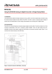
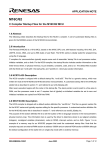
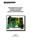
To use CPU Rewrite Mode, the memory structure and the control registers need to be identified. The memory
map of the M16C/62 is shown in Figure 1. Note that the flash is divided into blocks such that certain
erase/programming functions are done on a block basis. The boot flash area is used for serial I/O mode and is
not available for CPU Rewrite mode programming.
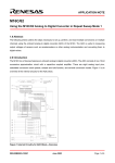
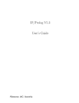
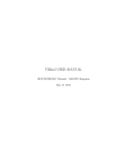
The “Flash Memory Control Register” (FMCR) is shown in Figure 2. Normally, only the first three LSBs are used
for CPU rewrite mode.
Beyond CPU registers, the flash memory has its own logic to handle erase and programming procedures. This is
the flash's “Write State Machine” (WSM). The WSM commands are given in Table 1.
REU05B0014-0100Z
June 2003
Page 1 of 22
M16C/62
Applications of M16C/62 Flash CPU Rewrite Mode
00000H
H
003FFH
00400H
SFR area
Internal RAM area
053FFH
External area
BFFFFH
C0000H
D0000H
E0000H
F0000H
Block 6: 64K bytes
Block 5: 64K bytes
Block 4: 64K bytes
Block 3: 32K bytes
F8000H
Block 2: 8K bytes
FA000H
Block 1: 8K bytes
FC000H
Block 0: 16K bytes
FFE00H
FFFFFH
Fixed vector
The boot flash is not in the 1M linear address space
and can only be accessed by coming out of reset in Boot Mode.
FE000H
FFFFFH
8K byte boot flash area
Figure 1 M16C/62 Memory Map
b7
X X
b0
0
Symbol
FMRC
Address
03b7H
At
XX000001
0: flash busy
1: flash ready
FMR00
RY/BY * flag
FMR01
CPU rewrite bit
0: Normal mode
1: CPU rewrite mode
FMR02
Lock bits disable bit
(allow lock bit erase)
0: flash block lock bits in effect
1: over-ride flash block lock bits
FMR03
Abort Current command
0: normal operation
1: reset flash
FMR05
ROM area select bit
(effective in boot mode only)
0: boot ROM area is selected
1: User ROM area is selected
Figure 2 Flash Memory Control Register
REU05B0014-0100Z
June 2003
Page 2 of 22
M16C/62
Applications of M16C/62 Flash CPU Rewrite Mode
Table 1 Flash Memory Control Register
2.1 Compatibility
This program is compatible with M16C/6x microcontrollers with page write (256 bytes) flash memory. It is NOT
compatible with word write MCUs such as the M16C/62P series. The driver is compatible with the above noted
MCUs on any Starter Kit/evaluation system running under the KD30 debugger. It CANNOT be evaluated or
demonstrated on any emulator using RAM to emulate flash (i.e., Renesas’ PC4701, Nohau, or Ashling emulator
systems).
2.2 Flash Programming Basics
The M16C/62's flash must be programmed in 256-byte pages on page boundaries (A0 – A7 = 00 – FEh), 16 bits
at a time. Attempts to program 8-bit data are ignored and even commands must be set as 16-bit words. The flash
can be “bulk” erased ('erase all unlocked blocks' command) or erased one block at a time (see memory map). Bit
erase state = 1. Once a block is erased, individual pages can be programmed at any time. The CPU rewrite
program can be stored in the flash, but because the WSM is common to all flash (all blocks), the CPU rewrite
code cannot execute out of flash. The rewrite code must be transferred to RAM before it can be executed.
3.0 Application
The example program includes 6 basic flash commands:
1. Erase a block
2. Program a page
3. Read flash status (SRD)
4. Clear flash status (SRD)
REU05B0014-0100Z
June 2003
Page 3 of 22
M16C/62
Applications of M16C/62 Flash CPU Rewrite Mode
5. Read a block lock bit
6. Lock a block
The program uses these commands to illustrate a few basic applications:
1. Save variables to flash & read them back into RAM
2. Copy the data in one block to another block
3. Write “constants” to flash
4. Use the flash for hours of operation
3.1 Methodology
3.1.1 Section Definitions
The most “transparent” method to manipulate the flash within a C program is to define specific memory sections.
The C language uses sections to distinguish between initialized variables, un-initialized variables, constants, and
so on. The NC30 compiler allows user-defined sections in RAM or ROM. For this example, the standard NC30
start-up file “sect30.inc” is modified and renamed to “WFsect30.inc”. This new file contains two extra sections: a
“flashsave” section for saving variables to flash, and a “parmblock” section for writing “constants” within a user
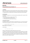
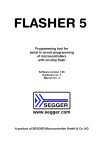
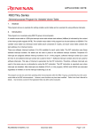
program. Figure 3 is the MAP view of the example program. Note that the “flashsave” section is not given an
absolute address so it starts right after the “bss” section.
Once the section is defined, placing the directive “#pragma SECTION” in a file redirects all constants or variables
to the new section until the next “#pragma SECTION” or the end of file is reached. For efficiency, the compiler
puts all integers at the start of each section (“even”) and the characters (“odd”) at the end of each section. This is
why the labels for the start and end of the “flashsave” section are integer and character respectively.
REU05B0014-0100Z
June 2003
Page 4 of 22
M16C/62
Applications of M16C/62 Flash CPU Rewrite Mode
Figure 3 Example Program MAP View
3.1.2 Writing Relocatable Code in C
As noted previously, CPU rewrite code cannot execute out of flash but must be moved to RAM. The M16C can
produce 100 percent relocatable code within a +/- 32k-address space. The NC30 C compiler generates
relocatable code for all functions in the same file within the +/- 32k-address restriction. This example program
utilizes these facts and the source code that executes out of RAM is written in C. The C code is compiled and
downloaded to flash, then the “copy_flash_code(void)” copies the code into RAM where it is executed.
3.1.3 Writing a Word to Flash
While the command to write to flash requires programming a complete page (256 bytes or 128 words), it does not
suggest that it is impossible to program a word at a time. The 'hours of operations' and 'write constant'
applications are examples of how to write a word at a time to flash. When programming a page, if all the data for
the page is not available, write blanks (1's) to the unused memory in that page.
4.0 Demonstration Program
4.1 General Notes
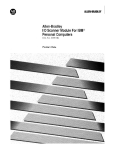
The demonstration program is designed to run on the MSV1632/62 board running under KD30 in “free run” mode,
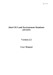
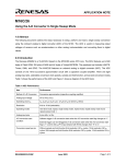
but the drivers (see RAM62.c) are meant for implementation within a user’s project. Figure 4 shows the flowchart
for the main demo function; flowcharts for the commands and application calls and given in section 7.0 Appendix.
The program minimizes passing absolute addresses because it could lead to accidental corruption of flash. The
REU05B0014-0100Z
June 2003
Page 5 of 22
M16C/62
Applications of M16C/62 Flash CPU Rewrite Mode
main() function is in file “flashmain.c”. The applications operate on blocks 2, 3, and 6 of the flash because block
1 is not available running under the ROM Monitor.
start
initialize MSA0654 display
get saved operating hours
tim e = operating hours
start hour timer
initalize CPU clock for
flash operations
copy CPURW code to
RAM
give variables values
write variables to Flash
copy one flash block to another
write a "constant" to flash
restore CPU clock
settings
copy saved variables to
RAM
write "00" to display
tim e > operating
hours?
yes
operating hours = operating hours + 1
initalize CPU clock for flash operations
write hours to flash
restore CPU clock settings
Figure 4 Demonstration Program (Main) Flowchart
REU05B0014-0100Z
June 2003
Page 6 of 22
M16C/62
Applications of M16C/62 Flash CPU Rewrite Mode
4.2 Demonstrating the Program
The program was developed to run on the MSV1632/62 Starter Kit, but it also works with any M16C/62 flash
system running the KD30 debugger in single chip mode. If using a different platform, it may be necessary to
remove the code that toggles Port P7-7.
Follow these steps to run the Demonstration (assumes user has a general understanding of the KD30
debugger):
1. Connect the MSV1632/62 board to a power source and the host PC.
2. Start KD30. In the “INIT” screen, click on the tab “run mode” and select “free run mode”.
3. Load the “flashapp.x30” file.
4. Open three memory windows to view the flash (Basic Window -> Dump Window).
5. Configure the windows to view the flash addresses used in the demo (click on any number in the address
column, and enter F0000h, F8000h, and C0000h for each window). Note the F0000h and C0000h flash
blocks are blank (all FF's) and the constants are in the F8000h block (scroll down to see the character
constants).
6. Insert a breakpoint in the main() function at the “getvarfromflash();” line.
7. Run the code: debug-> go free.
8. Hit the red “stop” button on KD30 (in “free run” mode, KD30 does not respond automatically to breakpoints).
9. View the memory at F0000h and C0000h. Note the test variables were saved to the beginning of the F0000h
block and that block was copied to the C0000h block.
10. Open a “memory window” (Basic window -> memory window) and find the 'testdata' in the “flashsave”
section (check your 'map viewer' in Tool Manager). Double-click on the variables and clear them.
11. Click “go”. Each time the LED (D6) toggles, the “hour meter” is updated (about every 5 seconds for demo).
12. Right after a toggle, click the “stop” button (i.e., you do not want to attempt to stop while writing to flash).
13. Open a C watch window (Basic Window -> C watch window -> global window) and note the 'testdata' has
been copied back from flash and the “oper_hrs” equals the number of LED toggles.
5.0 Implementing the Flash Drivers in a User Program
1. The “RAM62.c”, “fdevice.h”, “fl_util.c”, and “flash.h” files form the driver. Include “flash.h” in any project file
that requires driver functions. Add “RAM62.c” and “fl_util.c” to your project. These files require the “fdriver.h”
header file. Review the demonstration program and determine if the application requires user-defined
sections.
2. Before using any CPU rewrite commands, call “cpurw_ini()” and “copy_flash_code()” to set the flash
operation environment. The CPU rewrite code resides in the 512-byte array 'cpu_rw [ ]'. The actual code is
approximately 400 bytes. The extra array bytes allow the user to modify the CPU rewrite code.
REU05B0014-0100Z
June 2003
Page 7 of 22
M16C/62
Applications of M16C/62 Flash CPU Rewrite Mode
3. Table 2 lists the callable functions and describes how to use them. The functions do not return any error
codes and it is up to the user to supply the functions with valid parameters.
Table 2 Function calls
cpurw_ini()
Saves the current clock settings of the CPU, then changes the CPU frequency to f/2, and
adds a wait state. Not required if operating the CPU below 6 MHz.
restorestate()
Returns the CPU’s clock settings to the state before calling the function cpurw_ini().
copy_flash_code()
Copies the CPU rewrite code ( all of file “RAM62.c”) to RAM.
writeconstw(long ,int)
Writes a word to flash. Supply the address, long (must be an even address) and the
value to write, int.
copyvartoflash(int *, char *)
Writes variables in RAM to flash. Supply the starting address of the variables to copy in
RAM, int* and the ending address in RAM, char*. The differences in pointer types (int
and char) are due to the C compiler putting the integers at the beginning of a section
(“even”), followed by the characters (“odd”). The destination flash block is erased before
the copy. The destination written in flash is fixed in the function at the start of block 3
(F0000h).
getvarfromflash(int *ramptr,
char *endvars)
Reads the saved variables from the start of flash block 3 (F0000H) and writes them to
RAM. Basically, it is the reverse of “copyvartoflash()”.
copyblock(void)
Copies all of block 3 (F0000h) to the start of block 6 (C0000h). Block 6 is erased before
the copy. The blocks and addresses are fixed within the function.
ramcode (void);
This is the CPU rewrite code that executes out of RAM. The code must be copied to
RAM using “copy_flash_code()”. First, set the global variable “command”, then call
“ramcode()” to execute one of the following flash commands (see flash.h for command
codes)
•
•
•
•
•
•
erase a block
program a page
read flash status (SRD)
clear flash status (SRD)
read a block lock bit
lock a block
Note that the command codes used are the same as those for CPU rewrite codes. If a
command requires an address, put the 32-bit address into the global union “uaddr” (alias
“addrvar”). After executing the ‘read SRD’ command, the value is stored in global “SRD”.
After reading a block lock bit, the value is stored in global “lockbitstor”. The “program a
page” command will write the 256 bytes in the global “flashbuff [ ]” to the address in
“addrvar”.
REU05B0014-0100Z
June 2003
Page 8 of 22
M16C/62
Applications of M16C/62 Flash CPU Rewrite Mode
6.0 Reference
Renesas Technology Corporation Semiconductor Home Page
http://www.renesas.com
E-mail Support
[email protected]
Data Sheets
• 62AEDS.pdf - M16C/62A Specifications
User’s Manual
• cpurw62.pdf appnote - Programming the M16C/62 Flash in CPU Rewrite Mode
• 6020esm.pdf (Software Manual )
• 6020ec.pdf (C Manual )
• 6020easm.pdf (Assembler Manual)
• NC30ue.pdf (Compiler Manual)
REU05B0014-0100Z
June 2003
Page 9 of 22
M16C/62
Applications of M16C/62 Flash CPU Rewrite Mode
7.0 Appendix
RAMCODE
STARTUP
SEQUENCE
turn on CPU
rewrite mode
Start
decode
command
CMD =
41H
CMD =
20H
note1: turning off CPU
rewrite mode, disables
flash block C0000h
note2: read array
command resets the flash
memory.
CMD =
70H
CMD =
50H
CMD =
71H
CMD =
77H
RAMCODE EXIT
SEQUENCE
page program
block erase
read status
register
clear status
register
read block lock
bit
program block
lock bit
wait for flash
ready
send read
array
command to
flash.
(note 2)
wait for flash
ready
turn off CPU
rewrite mode
turn c0000h flash
block back on (note 1)
exit
Figure 5 Code in RAM Flowchart
REU05B0014-0100Z
June 2003
Page 10 of 22
M16C/62
Applications of M16C/62 Flash CPU Rewrite Mode
yes
page write
ramcode exit
sequence
Set
command =
41h
Set address
= flash page
address
Call
ramcode()
calling function
exit
code in RAM
code in ROM
code in ROM
ram code startup sequence
code in RAM
unlock all blocks
flash ready?
yes
progptr = 0
word[address] <- 41h
word[address] <progbuff[progptr]
progptr = progptr + 1
address = address +2
page done?
Figure 6 Page Write Flowchart
REU05B0014-0100Z
June 2003
Page 11 of 22
M16C/62
Applications of M16C/62 Flash CPU Rewrite Mode
block erase
calling function
Set command
= 20h
Set address =
last word
address of
block
Call ramcode()
code in ROM
ramcode startup
sequence
code in RAM
unlock all blocks
write erase command to block address
write confirm command to block address
ramcode exit
sequence
code in RAM
exit
code in ROM
Figure 7 Block Erase Flowchart
REU05B0014-0100Z
June 2003
Page 12 of 22
M16C/62
Applications of M16C/62 Flash CPU Rewrite Mode
block lock read
Set command =
71h
Set address =
last word
address of block
Call ramcode()
calling function
ramcode startup
sequence
code in ROM
code in RAM
M[address] <- 71h
lockbitstor = lockbit status
ramcode exit sequence
code in RAM
code in ROM
return
Figure 8 Block Lock Read Flowchart
REU05B0014-0100Z
June 2003
Page 13 of 22
M16C/62
Applications of M16C/62 Flash CPU Rewrite Mode
block lock write
Set command
= 77h
Set address =
last word
address of
block
Call ramcode()
calling function
code in ROM
ramcode startup
sequence
code in RAM
M[address] <- 77h
ramcode exit sequence
code in RAM
code in ROM
return
Figure 9 Block Lock Write Flowchart
REU05B0014-0100Z
June 2003
Page 14 of 22
M16C/62
Applications of M16C/62 Flash CPU Rewrite Mode
clear SRD
Set command =
50h
Call ramcode()
calling function
code in ROM
ramcode startup
sequence
code in RAM
write 50h to M(F0000H)
ramcode exit
sequence
code in RAM
exit
code in ROM
Figure 10 Clear SRD Flowchart
REU05B0014-0100Z
June 2003
Page 15 of 22
M16C/62
Applications of M16C/62 Flash CPU Rewrite Mode
read SRD
Set com m and =
70h
Call Ram code()
calling function
code in ROM
ram code startup
sequence
code in RAM
write 70h to M(F0000H)
SRD <- M(F0000H)
ram code exit
sequence
code in RAM
exit
code in ROM
Figure 11 Read SRD Flowchart
REU05B0014-0100Z
June 2003
Page 16 of 22
M16C/62
Applications of M16C/62 Flash CPU Rewrite Mode
get variables from
flash
rampointer = start of variable section
rompointer= start of flash block
M[rampointer] = M[rompointer]
increment rampointer
increment rompointer
all variables
copied?
yes
return
Figure 12 Get Variables from Flash Flowchart
REU05B0014-0100Z
June 2003
Page 17 of 22
M16C/62
Applications of M16C/62 Flash CPU Rewrite Mode
copy variables to
flash
erase destination
block
rampointer = start of variable section
flash address = start of flash block
copypointer = 0
flashbuffer[copypointer] = M[rampointer]
increment rampointer
increment copypointer
flash buffer full?
yes
set command = PAGE_PROGRAM
Code in RAM
Call ramcode()
flash address = flash address + 256
all variables
copied?
yes
return
Figure 13 Write to Flash Flowchart
REU05B0014-0100Z
June 2003
Page 18 of 22
M16C/62
Applications of M16C/62 Flash CPU Rewrite Mode
Write constant to
flash
Set address of
constant to write
Set value to
write
buffer offset = address of constant & FFh
flash page address = address of constant &
FFFF00h
Fill flash buffer
with blanks
(FFFFh)
flash buffer[buffer offset] = value
Code in RAM
Call ramcode()
return
Figure 14 Write Constant to Flash Flowchart
REU05B0014-0100Z
June 2003
Page 19 of 22
M16C/62
Applications of M16C/62 Flash CPU Rewrite Mode
copy block
erase destination
block
point to start of source block (source)
point to start of destination block
(destination)
copypointer = 0
flashbuffer[copypointer] = M[source]
increment source
increment copypointer
flash buffer
full?
yes
flash address = destination
set command = PAGE_PROGRAM
Call ramcode()
Code in RAM
destination = destination + 256
all of block
copied?
yes
return
Figure 15 Copy Block Flowchart
REU05B0014-0100Z
June 2003
Page 20 of 22
M16C/62
Applications of M16C/62 Flash CPU Rewrite Mode
Read hours of
operation
operating hours = 0
operating hours =
max # of hours
all flash hour bit
programmed?
get next word
from flash hour
block
is it FFFFh?
no
operating hours =
operating hours +
16
is it 0?
no
exit
no
LSBit = 0?
operating hours = operating hours + 1
shift word 1 bit right
Figure 16 Read Hours of Operation Flowchart
REU05B0014-0100Z
June 2003
Page 21 of 22
M16C/62
Applications of M16C/62 Flash CPU Rewrite Mode
Write Hours
all flash hour bits
programmed?
determine word in flash hour
block to program
WRITE HOURS OF
OPERATION
FROM FLASH
determine offset of word from
page boundary
determine bit in word to program
fill buffer with blanks
insert word into buffer at offset
determine flash page to write buffer to
set command = PAGE_PROGRAM
Call ramcode()
Code in RAM
exit
Figure 17 Write Hours of Operation from Flash Flowchart
REU05B0014-0100Z
June 2003
Page 22 of 22
Keep safety first in your circuit designs!
• Renesas Technology Corporation puts the maximum effort into making semiconductor products
better and more reliable, but there is always the possibility that trouble may occur with them. Trouble
with semiconductors may lead to personal injury, fire or property damage.
Remember to give due consideration to safety when making your circuit designs, with appropriate
measures such as (i) placement of substitutive, auxiliary circuits, (ii) use of nonflammable material or
(iii) prevention against any malfunction or mishap.
Notes regarding these materials
• These materials are intended as a reference to assist our customers in the selection of the Renesas
•
•
•
•
•
•
•
Technology Corporation product best suited to the customer's application; they do not convey any
license under any intellectual property rights, or any other rights, belonging to Renesas Technology
Corporation or a third party.
Renesas Technology Corporation assumes no responsibility for any damage, or infringement of any
third-party's rights, originating in the use of any product data, diagrams, charts, programs, algorithms,
or circuit application examples contained in these materials.
All information contained in these materials, including product data, diagrams, charts, programs and
algorithms represents information on products at the time of publication of these materials, and are
subject to change by Renesas Technology Corporation without notice due to product improvements
or other reasons. It is therefore recommended that customers contact Renesas Technology
Corporation or an authorized Renesas Technology Corporation product distributor for the latest
product information before purchasing a product listed herein.
The information described here may contain technical inaccuracies or typographical errors.
Renesas Technology Corporation assumes no responsibility for any damage, liability, or other loss
rising from these inaccuracies or errors.
Please also pay attention to information published by Renesas Technology Corporation by various
means, including the Renesas Technology Corporation Semiconductor home page
(http://www.renesas.com).
When using any or all of the information contained in these materials, including product data,
diagrams, charts, programs, and algorithms, please be sure to evaluate all information as a total
system before making a final decision on the applicability of the information and products. Renesas
Technology Corporation assumes no responsibility for any damage, liability or other loss resulting
from the information contained herein.
Renesas Technology Corporation semiconductors are not designed or manufactured for use in a
device or system that is used under circumstances in which human life is potentially at stake. Please
contact Renesas Technology Corporation or an authorized Renesas Technology Corporation product
distributor when considering the use of a product contained herein for any specific purposes, such as
apparatus or systems for transportation, vehicular, medical, aerospace, nuclear, or undersea
repeater use.
The prior written approval of Renesas Technology Corporation is necessary to reprint or reproduce in
whole or in part these materials.
If these products or technologies are subject to the Japanese export control restrictions, they must be
exported under a license from the Japanese government and cannot be imported into a country other
than the approved destination.
Any diversion or reexport contrary to the export control laws and regulations of Japan and/or the
country of destination is prohibited.
Please contact Renesas Technology Corporation for further details on these materials or the
products contained therein.