1
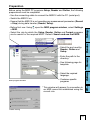
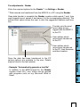
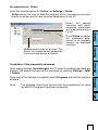
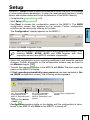
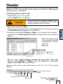
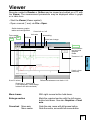
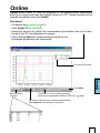
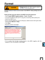
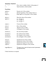
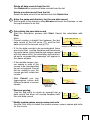
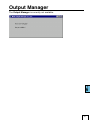
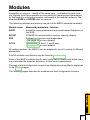
User manual
MSR 12
Instructions
operating instructions
Setup
PC software
Reader
Setup
Viewer
Reader
Other
modules
PC software
Modules
Online
PC…
Online
Viewer
Instructions
Setup
Reader
Viewer
Online
PC…
Contents . . . . . . . . . . . . . . . . . . . . . . . . . . . . . . . . . . . . . . . . . . . . . . . . . . 3
Important notes regarding this user manual . . . . . . . . . . . . . . . . . . . . . 4
Safety instructions and warnings . . . . . . . . . . . . . . . . . . . . . . . . . . . . . . 5
MSR 12 Modular Signal Recorder Operating Instructions . . . . . . . . . . 6
Overview . . . . . . . . . . . . . . . . . . . . . . . . . . . . . . . . . . . . . . . . . . . . . . . . . . 7
Controls . . . . . . . . . . . . . . . . . . . . . . . . . . . . . . . . . . . . . . . . . . . . . . . . . . 7
Connecting external sensors . . . . . . . . . . . . . . . . . . . . . . . . . . . . . . . . . . . 8
Turning the unit on . . . . . . . . . . . . . . . . . . . . . . . . . . . . . . . . . . . . . . . . . . . . 8
Selecting the main menu . . . . . . . . . . . . . . . . . . . . . . . . . . . . . . . . . . . . . . . 8
Displaying modules and sensors . . . . . . . . . . . . . . . . . . . . . . . . . . . . . . . . . 9
Displaying an online measurement . . . . . . . . . . . . . . . . . . . . . . . . . . . . . . . 10
Turning the online measurement mode on . . . . . . . . . . . . . . . . . . . . . 10
Adjusting the display mode . . . . . . . . . . . . . . . . . . . . . . . . . . . . . . . . . 10
Entering the sampling rate t . . . . . . . . . . . . . . . . . . . . . . . . . . 10
Entering the Y range . . . . . . . . . . . . . . . . . . . . . . . . . . . . . . . . 10
Entering the lowest value Ymin . . . . . . . . . . . . . . . . . . . . . . . . . 10
Selecting the graphical representation mode . . . . . . . . . . . . . . . . . . . 10
Rolling and Scrolling . . . . . . . . . . . . . . . . . . . . . . . . . . . . . . . . . . . . . . 10
Exiting the online measurement mode . . . . . . . . . . . . . . . . . . . . . . . . 10
Recording measurement parameters . . . . . . . . . . . . . . . . . . . . . . . . . . . . . 11
Starting data recording . . . . . . . . . . . . . . . . . . . . . . . . . . . . . . . . . . . . 11
Cancelling data recording . . . . . . . . . . . . . . . . . . . . . . . . . . . . . . . . . . 11
Notes on recording data . . . . . . . . . . . . . . . . . . . . . . . . . . . . . . . . . . . 11
Adjustments . . . . . . . . . . . . . . . . . . . . . . . . . . . . . . . . . . . . . . . . . . . . . . . . . 11
Measurement units . . . . . . . . . . . . . . . . . . . . . . . . . . . . . . . . . . . . . . . 11
Maintenance . . . . . . . . . . . . . . . . . . . . . . . . . . . . . . . . . . . . . . . . . . . . . . . . 12
User checks . . . . . . . . . . . . . . . . . . . . . . . . . . . . . . . . . . . . . . . . . . . . . 12
Cleaning . . . . . . . . . . . . . . . . . . . . . . . . . . . . . . . . . . . . . . . . . . . . . . . 12
Charging the battery . . . . . . . . . . . . . . . . . . . . . . . . . . . . . . . . . . . . . . 12
Battery and mains operation . . . . . . . . . . . . . . . . . . . . . . . . . . . . . . . . . . . . 13
Specifications . . . . . . . . . . . . . . . . . . . . . . . . . . . . . . . . . . . . . . . . . . . . . . . 13
Operating, transport and storage conditions . . . . . . . . . . . . . . . . . . . . . . . . 14
Troubleshooting . . . . . . . . . . . . . . . . . . . . . . . . . . . . . . . . . . . . . . . . . . . . . . 14
Packing list . . . . . . . . . . . . . . . . . . . . . . . . . . . . . . . . . . . . . . . . . . . . . . . . . 15
Warranty . . . . . . . . . . . . . . . . . . . . . . . . . . . . . . . . . . . . . . . . . . . . . . . . . . 15
Disposal . . . . . . . . . . . . . . . . . . . . . . . . . . . . . . . . . . . . . . . . . . . . . . . . . . . 15
MSR PC software . . . . . . . . . . . . . . . . . . . . . . . . . . . . . . . . . . . . . . . . . . . . 16
Setup . . . . . . . . . . . . . . . . . . . . . . . . . . . . . . . . . . . . . . . . . . . . . . . . . . 23
Reader . . . . . . . . . . . . . . . . . . . . . . . . . . . . . . . . . . . . . . . . . . . . . . . . 24
Viewer . . . . . . . . . . . . . . . . . . . . . . . . . . . . . . . . . . . . . . . . . . . . . . . . . 26
Online . . . . . . . . . . . . . . . . . . . . . . . . . . . . . . . . . . . . . . . . . . . . . . . . . 31
Other MSR PC software . . . . . . . . . . . . . . . . . . . . . . . . . . . . . . . . . . . 33
MSR 12-Modules . . . . . . . . . . . . . . . . . . . . . . . . . . . . . . . . . . . . . . . . . . . . 42
Modules
Contents
WARNING
Indicates that equipment may suffer damage or that there is a risk of injury to the operator or user should the instructions not be followed correctly.
CAUTION
Indicates that equipment may suffer damage or that data loss may occur should the instructions not be followed correctly.
Conventions
Press the arrow keypad in the
centre, without pressing the arrows. This functions as the Enter key.
Press the arrow
keypad in the
centre.
Setup
Selected function
Menu > Record >
Start
Select the Record function by
pressing
and
, open the Record menu using
, select
Start and press .
-> X
See page X
Viewer
Press right arrow on the arrow keypad.
Online
Press the symbols on the arrow
keypad in the direction shown.
Reader
Example
Record
-> 5
PC…
Description
Commands, menu items, functions, field names are shown in
bold.
•Reference to further information
•Further information
Modules
Term / Symbol
Commands, menu
items, functions,
field names
Instructions
In this manual notes of particular importance are presented as follows:
Setup
Important notes regarding this user manual
•Before using the MSR 12 check the unit itself and all cables for visible signs of
damage and never operate a damaged MSR 12. A damaged MSR 12 can endanger operator safety! Should the MSR 12 not function perfectly or appear to be damaged, send it to MSR Electronics GmbH for repair. •Ensure that no fluids enter the MSR 12's casing. Fluids cause corrosion damage and short-circuits inside the MSR 12.
• The MSR 12 casing, sensors, cables and mains adapter must never be
opened or modified. The manufacturer cannot be held liable for damage
resulting from use other than that for which the unit is intended, or from
improper operation of the unit.
•Use only original MSR 12 sensors, cables and mains adapters. •Never use an MSR 12 with a leaking battery. Should a battery leak be detected ensure that the electrolyte does not come into contact with the skin,
the eyes or the mouth. Should this occur, thoroughly rinse the affected area
with water for at least 15 minutes. Consult a doctor. Do not breathe in any vapours emitted. Immediately clean the electrolyte from the MSR 12 using
a soft cloth and dispose of the cloth subsequently. •Turn off the MSR 12 before connecting any plugs or sensors.
•The mains voltage stated on the mains adapter must not be exceeded.
•Observe the type plate on the mains adapter.
•Ensure the proper disposal of an obsolete MSR 12, together with the cable
and mains transformer ->15.
Instructions
Modules
PC…
CAUTION
Setup
•The MSR 12 is a unit for recording and displaying measurement parameters and may not be used for safety-related applications.
Reader
•Read the operating instructions carefully before using the MSR 12 or the
MSR software. This will protect you personally and avoid damage to the
unit.
Viewer
WARNING
Online
Safety instructions and warnings
MSR 12
Instructions
Operating Instructions
The MSR 12 Modular Signal Recorder is a modular unit for measuring, displaying and recording various physical measurement parameters. Measurements
may be carried out concurrently or using different measurement frequencies.
Due to its modular design the MSR 12 can easily be customised by adding or
replacing modules to provide the required functionality.
Each module has a range of sensors – mostly of a similar type. For test purposes
the gradient curve and the actual measurement parameters for the selected
sensor may be shown on the unit's display. The readings are processed by the
module's own processor and saved in the module’s memory.
The base module of the MSR 12 includes a temperature sensor,
a pressure sensor and three accelerometers (X, Y and Z-axes). A list of additional modules and sensors may be found at www.
msr.ch.
MSR 12
Mains adapter
PC connection
cable
CD with MSR
software
Controls
Instructions
Overview
Instructions
Connecting external sensors
Connect all the required sensors to the MSR 12 using the cables supplied.
The MSR 12 only recognises sensors that are connected when the unit is switched on.
Socket for
sensors
Turning the unit on
Connect all the required sensors before turning on
the MSR 12. Press down the on / off switch and wait until the
MSR 12 display turns on:
The following information appears on the display:
On/off switch
Software version
Battery symbol, battery level
Number of modules and sensors connected
Current date
Current time
Memory available
Recording on / off
Using mains power
Note: The MSR 12 automatically reverts to this display after 30 seconds idle time.
Selecting the main menu
Press
after the unit has been turned on to open
the main menu.
The following instructions assume that the MSR 12
is displaying the main menu and that all sensors are
connected.
Pressing
will return to the initial display that appears when the unit is turned on.
Opens the selected menu
item.
Instructions
Displaying modules and sensors
Selecting the module
Open the list of all available modules by pressing Modules
(one module consists of several sensors, which are usually of the same type).
Select the required module using and and open
the list of sensors by pressing . Selected module
Selecting the sensor to display
Press
and
to select the sensor for which
you wish to display measurement parameters and
curves and confirm your selection by pressing . Note: The online display can be turned on by
pressing Online .
Menu
Modules
ACC
x
y
z
Selected sensor
Instructions
Displaying an online measurement
In addition to recording measurement parameters
to memory the MSR 12 can also display the reading
and gradient across a sensor for test purposes.
t
Turning the online measurement mode on
Turn the Online measurement function on by press- Y
ing , select the desired sensor with
and
and
adjust the display mode to your requirements.
Ymin
Adjusting the display mode
Select the display mode using
and . The display mode options can be changed by pressing
and .
•Entering the sampling rate t
Select the display mode option t = … using
and , then use
and
to set the sampling
rate that you want to display. ACC
x=-1.08 g
Module
name
Sensor name
Current reading
Unit*
*Can be changed via the
MSR Setup. -> 10
•Entering the Y range
Select the display mode option Y= … using
and , then use
and
to set the range that
you want the MSR 12 to display.
•Entering the lowest value Ymin
Select the display mode option Ymin= … using
and , then change the value using and .
Selecting the graphical representation mode
The MSR 12 can display graphic curves in either Rolling or Scrolling mode.
Rolling and Scrolling is accessed via Setup
>
Display . Select the required graphical representation mode and confirm by pressing .
With the Scrolling option – in the style of a tradition-al data recorder – a “paper roll” is traced on the
right-hand edge of the screen. The “paper” transits
the display from right to left
With the Rolling option the “trace” transits the display from left to right. Once it has reached the righthand edge it returns to the left and begins to overwrite the old curve. Exiting the online measurement mode
Exit the online measurement mode by pressing
The display returns to the main menu.
. 10
Each module incorporated into the MSR 12 has its own dedicated memory in
which the measurement parameters of the sensors attached to that module are
recorded.
Starting data recording (Record)
From the main menu select Record
> Start
. During the recording process the green LED flashes.
Cancelling data recording
From the main menu select Record > Stop .
Turning the MSR 12 off will also stop data recording.
If the memory is full then this can also stop data from being recorded. See also
->14 (troubleshooting)
Notes on recording data
The data recording process is not affected by the status of the online display.
Using the MSR PC Setup software (->23) it is possible to select the modules
from the PC for which the MSR 12 is to record the measurement parameters. In addition, the frequency of measurement and recording can be set and the
behaviour of the memory controlled.
The measurement parameters can be transferred to a PC once the data recording process is complete (MSR PC software > Reader).(->24)
Adjustments
Measurement units
The measurement unit of the selected sensor can be adjusted to suit requirements.
From the main menu select Options
, Units
Select the required unit by pressing
and
. . The measurement unit set then applies to all similar sensors connected to the
currently active module. Confirm your selection by pressing
.
11
Instructions
Recording measurement parameters
User checks
•Check the MSR 12 before each use. •Before using the MSR 12 check both the unit itself and all cables for visible
signs of damage.
•Check the functions of the MSR 12.
•Never use an MSR 12 that is damaged or not functioning perfectly. Never use
damaged accessories.
•Ensure
that the battery is sufficiently charged for the required period of use.
Should the MSR 12 not function perfectly or should damage become apparent
send the unit to MSR Electronics GmbH for repair. Repairs may only be carried
out by MSR Electronics GmbH or an authorised dealer. Defective or damaged
components may only be replaced with manufacturer’s original parts.
Cleaning
• Ensure that no fluids enter the MSR 12's casing. Fluids will cause corrosion damage and
short circuits.
•Never use corrosive or abrasive cleaning agents or polishes.
•Cleaning agents containing additives such as alcohol will cause the case
to become matt and/or brittle.
CAUTION
•Clean the MSR 12 when necessary.
•Before cleaning, turn the unit off and disconnect it from the mains supply. •Use a cleaning agent suitable for plastic or a cloth dampened with water and
soap.
Charging the battery
Before first use:
The battery is not fully charged on delivery and should
be charged for approx. 5 hours before using the
MSR 12 for the first time.
Use the mains adapter supplied and charge the MSR 12:
•Before each use
•When the battery level indicator shows
•At least every two months
Method:
•Turn the MSR 12 off and remove the plugs for the sensor and the PC cable. •Connect the mains adapter to the MSR 12 and plug the adapter into a mains
out-let. The yellow LED and the arrow next to the battery symbol
indicate that the MSR 12 is using mains power.
•Charging is complete when the battery symbol indicates full
. •Unlock and unplug the mains adapter once charging is complete.
Notes:
•Please observe also the type plate on the mains adapter.
•Recorded data is non-volatile and remains in the unit’s memory
even when the battery is exhausted.
12
Instructions
Maintenance
The MSR 12 is powered by its built-in batteries. When charging the batteries,
the mains adapter supplied is connected to the unit in place of the external
sensors.
WARNING
For medical applications the MSR 12 may not
be powered using the mains adapter.
Using an optionally available plug, the unit may be powered by the mains
adapter even when external sensors are attached.
Specifications
Size:
MSR 12: (L x H x W) ca. approx. 137 x 74 x 27mm Connecting cable: approx. 50cm Weight:
Power supply: MSR 12: approx. 180g Battery*: 3.6 V 880mAh NiMH
Backup battery*: 3.0 V LiMn
Battery life (unit turned off): approx. 2 months
*Not user replaceable.
Classification: Class III equipment For information relating to the modules and sensor specifications, please refer
to the module chapter.
13
Instructions
Battery and mains operation
• Protect the MSR 12 from excessive exposure to the sun and other sources of
heat. Avoid heavy impacts.
• Do not place heavy objects on top of the MSR 12.
• Only store the MSR 12 in a dry, dust-free environment.
• Operating temperature: 0 °C to 50 °C
• Storage temperature: -20 °C to 70 °C
• Avoid contact with water and moisture.
• Relative humidity: 30% to 95% max. (Storage and transport 10-95%). Troubleshooting
Problem
Possible cause
Possible solution
Data recording
stops automatically
The memory of at least
one module
is full.
•Back-up data.
•Check the overwrite
mode and measurement
frequency of all modules
(MSR PC software
->Setup). ->23
“No channel” appears on the
MSR 12 display.
•MSR 12 does not recognise the sensors.
•Check the sensor’s connections
•Turn the MSR 12 off and
back on again.
14
Instructions
Operating, transport and storage conditions
•MSR
•User manual
Options: •Mains adapter
•MSR RS232 cable
•Warranty card
•MSR PC software
Instructions
Packing list
•Protective case
•Additional sensors
•Adapter for connecting
further sensors
•RS232-USB converter
•RS232 optical coupler
Warranty
See warranty card.
Disposal
Take the MSR 12 to a municipal waste disposal centre or return it to MSR
Electronics GmbH. The MSR 12 must not be disposed of in normal domestic
waste.
15
Setup
PC software
Reader
Setup
Viewer
Reader
Online
Viewer
Online
PC software
PC…
Other
16
PC software
PC…
Version number of MSR CD
Reader
Insert the CD containing the MSR PC software into the computer’s CD-ROM
drive. The installation procedure starts automatically*. During installation select: Run MSR Modular Signal Recorder now.
appears on screen.
The MSR symbol
If the PC is not set up for automatic installation, proceed as follows:
1. Click Start > Run
2. Click Find > Look in: (set to CD drive). 3. Select the file Install_MSR.exe and Open.
4. In the Run dialog box click OK.
5. The installation process will begin. 6. Follow the instructions and select: Run MSR Modular Signal Recorder
now.
or
7. The MSR software may be started by clicking on the MSR symbol
via Start > Programs > MSR > MSR.
Viewer
Installation of the MSR PC software on a PC
Online
External processing of MSR 12 data is carried out using the MSR PC software
programs Setup, Reader, Viewer and Online. The MSR PC programs can be
used for all MSR types.
The Setup enables the properties of the MSR 12 and attached modules to be
customised to user’s requirements.
The Reader allows the user to transfer measurement parameters to a Windows
PC. The Viewer is used to display data graphically or in table form or to exportit
as a text file (*.csv).
With the help of Online users can view measurement parameters and curves
“live” on a PC. Setup
Overview
Version numbers
of MSR PC
programs
MSR program window
*The program "Inno Setup" for installing the MSR PC programs was written by Jordan Russell (www.jrsoftware.org, copyright
Jordan Russell).
17
Uninstalling
The software is uninstalled via the computer’s operating system (Programs >
MSR > Uninstall MSR). System Requirements
PC…
Online
Viewer
Reader
Setup
•Windows 95 or higher
•Serial port RS 232 or USB port with RS 232 converter
18
Preparation
•Enter the path to the directory.
•See following page for
template.
•Customer-specific programs
*This window will appear if a connection to
an MSR cannot be established using the
current rule.
Loader Dialog
19
PC…
MSR program window
Online
•Select the required language.
Reader
•Select the port used by
Reader, Online and
Setup. Viewer
•Before first use: Using open the MSR program window, select Settings > MSR.
• Select the rule by which the Setup, Reader, Online and Format programs
are to search for the required MSR*. Default: Search and use first MSR.
Setup
Before using the MSR PC programs Setup, Reader and Online, the following
preparations must be completed:
•Use the connecting cable to connect the MSR 12 with the PC (serial port).
•Switch the MSR 12 on.
• Ensure that the MSR 12 is not recording any measurement parameters (Record
> Stop) during data transfer (Reader, Setup).
Template
Reader
PC…
Online
1.Assign right hand axis and blue colour shades to temperature in Viewer. 2.Save as template (Bluetemp.mse).
3.Generate new templates for Reader and Online: Select MSR program window, Settings MSR > Template , enter new name and path
(Temperature.mse), then Open.
4.Open the still blank template (Temperature.mse) using .
5.Import the template that was created in Viewer (Bluetemp.mse). Select the required sensors (tick in checkbox) in the Module column
and confirm with Accept.
6.Edit the displayed list: First select a sensor in the Module column and
then choose Edit.
7.Change the name “HUM, T1” to “Outside temperature”, and Accept.
8.Continue to make the necessary adjustments and confirm them with
Accept.
Viewer
Example
The temperature curves are required to be blue and oriented on the right
hand axis in all display modes.
Setup
The template, selected via Setting > MSR (*.mse), defines which sensors the Reader reads out as standard or are displayed in Online. The
template sets the colour of the trace, the positioning of its axis (left, right)
and gives the sensors a name (“HUM, T1” is required to be displayed as
“outside temperature”, for example). Templates can be produced on the
basis of examples contained in Viewer (->26).
20
Pre-adjustments - Reader
Enter the required options for the Reader** via Settings > Reader. **Data records are transferred from the MSR 12 to a PC using the Reader.
User defines which records are transferred
to the PC, their filenames
and their location.
Online
Once the data has been transferred to the PC
various options are available to the user. Details
may be found in the text window.
Reader
User defines which records are transferred
to the PC.
Viewer
Transfer only the most
recent data record
logged with the MSR 12
to the PC. Setup
Once data transfer is complete the Reader creates a data record (*.msr) from
each logged record, names it and saves it in the corresponding directory. The
bottom-most option allows the user to alter the suggested filename and location. PC…
•Example "Automatically generate a text file"
In addition to the MSR format file, the Reader creates a text file (*.csv), which can be opened
with programs such as e.g. Microsoft Word or
Excel. 21
Pre-adjustments - Online
•Select the desired
frequency with which
measured parameters
are to be transferred to
the PC. •Once Online is started
the measured para-
meters of all available
sensors are displayed
onscreen.
Upon exiting Settings (Einstellungen) the PC saves the settings that were last
entered. The default settings can be reinstated by selecting Settings > MSR
> Default.
Once entry of the settings is complete, select Programs and start the required
program.
The following instructions assume that the preparations for using
the MSR PC programs have been completed.
PC…
Note: Online
Completion of the preparatory measures
Viewer
Reader
•Online can be used as a server. This
allows the measurement parameters
to be accessed across a network. Setup
Enter the required options for Online* via Settings > Online.
* Online allows the user to view the progress of the measurement process
directly on-screen and to save recorded parameters on the PC.
22
From a PC, Setup is used to select the modules for which the MSR 12 is required
to save measurement parameters, to enter the measurement frequency, modify
sensor and module names and to set the behaviour of the MSR’s memory.
•Complete the preparations (->19).
•Start Setup (Setup symbol)
•Use Read to access the configuration saved in the MSR 12. The BASE
configuration screen then appears on the monitor. Further configuration
screens can be selected by clicking on the tabs.
The Configuration* display appears on the MSR 12.
Setup
Setup
A section of the BASE configuration screen
Each of the MSR 12’s modules has its own configuration screen. The modules BASE, BCOM, ACC3 and PR3 together with their respective sensors are MSR 12 standard components.
•Select the configuration screen requiring modification and make the required
changes. Further information on the configuration screens may be found in
the Module chapter ->42.
•Transfer the new configuration to the MSR 12 with Write. The main menu appears on the MSR 12’s display.
•If Start recording automatically upon power on has been selected in Setup (BASE configuration screen), the following window appears:
Yes: The configuration
is transferred to the
MSR 12. Recording then
starts.
To cancel: See Module
> BASE ->43
No: The configuration
is transferred to the
MSR 12. Recording is not
started.
Cancel: Stops configuration
transfer.
*Configuration remains visible on the display until the configuration is transferred to the MSR 12 with Write or the MSR 12 is turned off.
23
Reader
With the Reader users can selectively transfer data records logged with the
MSR 12 to a PC. The transfer process does not delete any measurement
records saved on the MSR 12.
Transferring data records to a PC
•Complete the preparations (->19).
•Start the Reader (Reader symbol)
Once data transfer has started (Start) all data
records saved on the MSR 12 can be over-
written if required (circular buffer). •Begin data transfer with Start. (In the case of protected data records the password* must first be entered.)
The Read Data display appears on the MSR 12.
The options selected under Settings > Reader (->21) influence the next steps:
•Under the option Read selected records the following data entry dialog box
appears:
•Select the data records
to be transferred and the
corresponding module. ->25
• Click OK.
->25
•With the option Read selected records and save with “Save dialog as” under Settings > Reader (->21) the filenames and locations
suggested by Reader can be overwritten.
Once the data records have been saved on the PC a list of files created
appears.
Serial number
Date (YYMMDD)
Recording start time (HHMMSS)
Copy number
Filenames allocated by the
Reader
*Forgotten your password?
See Format ->35.
24
Reader
CAUTION
More on the selective list
3 of the 4 modules of the record
are transferred to the PC. Modify
the selection with:
Show record details
t
OK The modules of this
record have the same
start time.
t The modules of this record
have different start times.
Reader
3/4
Number of recorded pages (record
size)
25
Viewer
Records created in Reader or Online may be viewed and edited on a PC with
the Viewer. The measurement parameters may be displayed either in graph
or in table form.
•Start the Viewer (Viewer symbol).
•Open a record (*.msr) via File > Open.
Switch between graphs,
tables and configuration
Cross-hair on / off
Lock axis Text created
using the text
mode
Gridlines
Autoscaling
Undo last change
Text mode
Shift between
text tool and
graphics
mode
Viewer
Traces on / off
X-axis = time
(seconds)
Difference between cross-hairs 1 & 2
X and Y values:
Cross-hair 1, cross-hair 2
(The displayed Y value always
relates to the left-hand axis)
Move traces
Enlarge section
Cross-hair
With right mouse button held down.
Move axis: Move centre:
Mark the required section with the left mouse
button held down. See also Graphics > Fixed
axis.
Grab the axis, move with left mouse button.
Grab the centre, move with left mouse button.
26
File
The File menu is used to Open records , to
Reopen (Open again) the most recently used
records and to Save the currently open record as
displayed .
With Save time window as the measurement parameters of the displayed time window are saved. (The measurement parameters of the hidden traces are also saved). For further options see Cutter
->34.
Templates help to standardise the displays, enable
easy repetition when reselecting the same sensors
and the same printing format. Creating templates: Adjust the display with Graph
and Configuration and save via File > Save as
template (file type: *.mse). Export Time window as text exports the measurement parameters of the displayed time window in
*.csv format. The measurement parameters of the
hidden traces are also exported. The trace can be exported in Bitmap (*. bmp) or as
JPEG format. Print preview opens a preview of the trace/graph. Print opens the print dialog box. Exit closes the Viewer. If changes were made
the user is asked whether the changes should be
saved. Note: The program saves changes as “Template” (*. mse). The template is automatically saved in the
record’s directory. Template (*. mse) and record (*. msr) have the same name.
Upon Opening a record the Viewer searches for
the template associated with that record. Should the
template not be located in the same directory as the
record then the standard format will be opened.
27
Viewer
Apply a template to the displayed record:
File > Use template then select the required template (*mse).
View
The View menu allows measurement parameters to be displayed as a Graph
or Table . Alternatively, using Configuration
the display
method can be customised to the user’s requirements. Graph
Gridlines can be shown for each axis (bottom, left,
right). •Select the required section with the left mouse button held down. The section is displayed enlarged. •For closer viewing, lock the time window ( ) or
range of values to the left or right axis ( / ). Several axes can be locked.
•With the left mouse button held down, select the
required detail. The enlargement is displayed
without altering the time segment or range of values of the locked axes. A further click releases the lock.
Auto scal clears all locked axes.
Using the two Crosshairs values can be measured
on the X and Y traces. X and Y differences can be
evaluated with the second cross-hair. The Y values
displayed are always associated with the left axis. With Detailed legend traces can be turned on and
off in the list of sensors. The complete record is displayed by selecting
Auto scale .
Auto scale clears all locked axes.
Undo
undoes the last enlargement. As long as
the Configuration dialog
is not quitted, Undo
allows the last changes made to the displayed
configuration screen to be undone.
28
Viewer
Fixed axis simplifies the amount of detail shown
within a time window or range of values. Table (Tabelle)
Go to time
allows users to jump straight to the
line in the table with the required time. Jump to beginning of graph
causes the table
to jump to the first measurement values displayed
in the graph. Configuration
As long as the Configuration dialog is not quitted, Undo
allows the last changes made to the
configuration screen to be undone. Text mode
Using the text mode you can insert texts at any
place.
you can activate and deactivate
By clicking on
the text mode.
Delete text:
•Click on
. The viewer displays
"Text 1" in the upper left corner.
•Drag the text field to the desired
place.
•Double click on the text field and
enter your required text.
•Click with the right mouse button
on the text field and select Delete. Text field with X and Y values:
•place the crosshairs (->26) on your
chosen position to adoddopt the X
and Y values you would like to use
in the text field.
•Create a text field (see above) and
click on the right mouse button. Select the desired representation.
29
Viewer
Insert text:
Configuration allows the display method of the
measurement parameters to be set with the help of
the configuration screens. Entering title and footer information is achieved via
Configuration > General.
The associated sensor name, assignment to the
left or right axis, the colour, line weight and style
can be set for each curve.
Axis > inactive allows the graph curve to be shown
or hidden as required. CAUTION
Using Configuration >Time axis X, the time axis
can be annotated, the time segment to be displayed
can be set, and the Increment for the lettering and
ruled lines, together with the Format for numbers
can be entered. Automatic axis annotation with an Increment of 0
(zero).
The number Format for the displayed X and Y values is entered via Configuration > Crosshairs.
The displayed Y value always relates to the left
axis. As long as Configuration is not quitted, users can
undo the last changes made to the displayed configuration screen with .
Quit Configuration
via Graph
or Table . Upon quitting, the Viewer saves the configuration.
30
Viewer
Depiction of the curves using points (Configuration
> Points/Curves > Yes) requires more
computing power, possibly leading to problems.
Online
Online allows users to view the progress of the measurement parameters
directly on-screen and save the logged values on a PC. Saved records can be
opened and edited using the Viewer. Procedure:
•Complete the preparations ->19.
•Start Online (Online symbol).
•Select the sensors for which the measurement parameters are to be transferred to the PC and displayed on-screen. •Upon clicking Next the measurement parameters are
presented graphically and numerically.
Online
Turn trace on and off
Exit Online
Back to sensor
selection
The MSR 12 is not currently recording
measurement parameters (MSR 12: Record >
Stop).
Pauses the transmission of measured parameters. With Continue, transmission is resumed.
31
For recurring applications in Online, Templates assist in
selecting the required sensors and adjusting the display to
suit.
Create template: Start Online and select the required sensors. Select Next. With Graph > Properties and Graph >
Gridlines, change the display properties of the traces. Via
Back return to the trace display. Interrupt recording with
Stop. Save the template via File > Save as template. Apply the template to Online: File > Use template and select the required template (*mse).
Once recording has finished by clicking on Stop, the recorded measurement parameters and traces can be deleted via Clear. The display properties can be changed via Properties and
Gridline. Select the frequency (Refresh rate) with which measurement parameters are to be transferred to the PC.
Notes •The MSR’s arrow keypad is locked during data transmission
and for 10 seconds thereafter. •Online may also be used while the MSR 12 is recording measurement parameters. •Measurement parameters can be polled via a server in Online.
32
Online
Once recording has finished by clicking on Stop, the recorded measurement parameters can be saved via File >
Save as.
CSV
The CSV utility creates text files (*.csv) from data records (*.msr). These may
subsequently be opened and edited in a word processing or spreadsheet
application.
Creating a text file
•Start CSV (MSR Program window > Tools > Csv).
•Click on Start and select the data record from which the text file is to be created.
CSV creates a text file (*.csv) and saves it in the corresponding directory
for that data record. Text file (*.csv) and data record (*.msr) have the same
name.
Note: If a template (*.mse) exists for the data record in question, CSV
takes this into account when creating the text file. Example: Opening a CSV text file with Excel
•Start the word-processing or spreadsheet program.
•Open the CSV file via File > Open. •Under File type , select Text Files.
Data source
MSR 12 name
Serial number
MSR 12 revision number
Measured parameters (data) in chronological
order
Excel file with measured data
Time of recording
33
PC…
Record start time:
Date (Day.Month.Year) and time of day (Hr:
Min:Sec)
Modules for which measurement parameters
were recorded
Module version
Channel and sensor names
Unit for the displayed value
Cutter
The Cutter utility creates an extract from a data record (*.msr). Creating an extract from a data record
•Start the Cutter utility (MSR Program window > Tools > Cutter).
•Click on Start and select the data record from
which the extract is to be created. •Select the time window. Beginning / End.
•Select the sensors for which the measurement
parameters are to be exported to a new data
record and click Next.
PC…
•Enter the name and directory for the new data
record. Click on Save. 34
Format
CAUTION
Format deletes all data records saved in the MSR 12 and the password!
Format deletes all data records saved in the MSR 12. Setup settings are not
deleted.
•If it is certain that all data records saved in the MSR, together with the
password, are to be deleted, select Start.
35
PC…
Delete all data records saved in the MSR 12 and the password
•Start Format (MSR Program window > Tools > Format).
•Connect the MSR 12 with the PC using the connecting cable (serial port).
•Switch the MSR 12 on.
•Ensure that the MSR 12 is not recording any measurements during the deletion process (Record > Stop).
•Click Start. •Read the caution messages. Calc
With Calc curves from existing data records can be linked to each other using
formulae and saved as a data record (*.msr). The saved data record can be
displayed and processed in the form of curves or as a table using the Viewer. Templates simplify the processing of recurring tasks.
Computing new curves
•Start Calc (MSR program window > Tools > Calc)
Open
data
record
2
1
4
3
Enter formula
1 Open data record (data origin)
Click on Open to open the data record for which you want to perform calculations on the curve. It is possible to open multiple data records.
2 Create new curves
From imported curves select the curve that you want to use for your calculations and drag it – with the left mouse button pressed – to the right into
the field for curves to be plotted. Repeat this procedure until the required
number of curves is shown on the right.
3
formula
Enter
Enter the formula to be used for the new curve into the Formula column. For this, use the capital letters on the left.
Example for a subtraction: A-C
You will find a list of the available functions at the end of this section or
under Help.
Modify the text for the new curves
The entries in the columns Module, Sensor and Unit can be modified.
PC…
Number field
36
Modify the order of the new curves
With the left mouse button pressed, drag the number field
to the required position.
Delete new curves
Click inside the number field of the curve to be deleted and
then press the delete key. Via Template > Delete plotted
curve, all new curves can be simultaneously deleted.
Note:
and saving the new curves
Calculating
Click on Calculate then enter the name and set the directory for the new data record. Click on Save.
The curves are saved as data records (*.mrs). The saved
measurement parameters can be displayed and processed
as a curve or as a table by the Viewer. Intermediate values
are interpolated.
Only curves that overlap timewise can be calculated.
Creating a template for processing recurring tasks
Once you have created the new curves you can save their
labels and formulae as a template (*.mse). (Template >
Write).
Creating new curves using templates
Open the required template (*mse) via Template > Read. This will automatically generate a number of new curves.
Multiple templates may be used to generate new curves. Each template generates a number of new curves.
PC…
4
37
Operators / brackets
+ - * / ^
Plus, minus, multiply, divide, to the power of
( )
Open brackets, close brackets
sqrt(no.)
Square root of the number
ln(no.)
Natural logarithm of the number (base e)
exp(no.)
Raise basis e to the power of the number
abs(no.)
Absolute value of the number
sgn(no.)
no. >0: sgn = 1
no. =0: sgn = 0
no. <0: sgn = -1
cos(no.)
Cosine of the number
sin(no.)
Sine of the number
tan(no.)
Tangent of the number
ctg(no.)
Cotangent of the number
arcsin(no.)
Arc sine of the number
arccos(no.)
Arc cosine of the number
arctan(no.)
Arc tangent of the number
arcctan(no.)
Arc cotangent of the number
sinh(no.)
Hyperbolic sine of the number
cosh(no.)
Hyperbolic cosine of the number
tangh(no.)
Hyperbolic tangent of the number
ctgh(no.)
Hyperbolic cotangent of the number
toggleSgn(no.)
Changes every second measurement parameter
sign (plus/minus)
PC…
Functions
Further functions on request
38
Concat
With Concat (concatenate = to link) data records can be linked together and
saved as a new data record (*.msr). The newly created data record can be displayed and processed in the form of curves or as a table using the Viewer. p
Data
record1
T0
p
Data
record2
T1 T2
Before concatenation
Time
T0
NewDatarecord3
T1 T2
Time
After concatenation
Concatenating several data records
Start Concat (MSR program window > Tools > Concat)
List of data records to be concatenated
1
2
3
Number window
Status window
1 Select the data records to be concatenated
Open the data records that you want to concatenate by clicking Add. Note that the list must be in chronological order such that the oldest data
record is at the top. Therefore either open the oldest data record first or
sort the list afterwards (see below). Sort the list alphabetically
Use Sort to sort the list alphabetically.
Data records that have automatically generated filenames (->21) can be
chronologically sorted using Sort.
PC…
Modify the data record order
With the left mouse button pressed, drag the number field to the required
position. 39
Delete all data records from the list
Use Delete all to remove all data records from the list. Delete one data record from the list
Select the data record to be deleted and click Delete line. 2 Enter the name and directory for the new data record
Set the path to the directory using Browse and enter the filename, or use
the input window to do this.
3 Calculating the new data record
Start the calculation process with Start. Cancel the calculation with
Stop.
p
Note: Newdatarecord3
•Concat creates a straight line between the last
data record of the first curve (T1) and the first
data record of the second curve (T2).
T0
T1 T2
Time
StraightlinecreatedbyConcat
•If, for the data records to be concatenated, there
are curves that overlap timewise and these have p
the same name (same module and sensor names
with the same units), the calculation will be aborted and a corresponding message* will appear in
the status window.
•If the module names, sensor names or units of the
curves to be concatenated
do not correspond Concat
will be unable to join the
curves and will create two
curves.**
•With Concat you can
superimpose curves with
different module or sensor
names.
p
Sensorp1 Sensorp2
Differentsensor
names
p
Time
p1
p1
Overlapping
Time
Sensorp1 Sensorp2
Newdatarecord
Time
p
p
Differentsensor Time
namesand
starttimes
*Remove overlap
Use the Cut utility to create an excerpt from a p
data record that does not overlap timewise with
the next data record.
Newdatarecord Time
PC…
p1
p1
Removeoverlap
Time
**Modify module names, sensor names and units
Use the Calc utility to match the module names, sensor names and units
for the curves.
40
Output Manager
PC…
The Output Manager is currently not available.
41
Modules
A selection of sensors – mostly of the same type – is attached to each module. Signals from these sensors are converted into measurement parameters
by the module’s on-board processors and saved in the module’s memory. The
modules BASE and BCOM have no sensors.
The following modules and sensors are part of the MSR’s standard hardware:
Module name Measured parameters / function BASE
Saves the setup parameters and measurement behaviour of
the MSR
BCOM
PC/MSR 12 communication module, capacity display
PR3
Ambient air pressure and temperature
(See page 45 for more details)
ACC3
Acceleration in the X, Y and Z axes
(See page 47 for more details)
By adding modules, the MSR 12 can be adapted to record a variety of different
parameters.
A list of modules and sensors may be found at www.msr.ch.
Each of the MSR’s modules has its own configuration screen with which users
can customise the module’s behaviour to their exact requirements.
The way in which configuration screens are displayed and modified is explained
in the Setup chapter.
Modules
The following pages describe the modules and their configuration screens.
42
BASE standard module
The standard module is incorporated into each MSR 12. It stores the parameters for Setup and the measurement performance settings of the MSR 12.
BASE configuration screen
Data records may only be
transferred from the MSR 12
to a PC upon entering a
password*. Module name
(max. 4 characters)
*Forgotten the password?
See Format ->35.
Identifying character for the MSR 12 in use.
Replaces the displayed values with default values.
MSR 12
device name
when the MSR 12 is switched
on.
When the option At any
time is enabled the automatic recording function of
the MSR 12 can be cancelled
with Record > Stop.
When the option Only during
countdown is enabled it is
possible to prevent the start of
recording with
and then .
Once the countdown has
ended the MSR 12 records
the measurement parameters.
Recording can be cancelled
by switching the MSR 12 off.
Not accessible to
users.
The MSR 12 display can be adjusted to the user’s preferences
with the brightness and contrast controls.
The backlight of the MSR’s display switches off automatically
after the unit has been idle for
approx. 3 seconds.
43
Modules
Recording starts automatically
BCOM communication module
The BCOM communication module is incorporated as standard into each
MSR 12. It regulates the transfer of data between a PC and the MSR 12.
BCOM configuration screen
Module name (max. 4 characters) Replaces the displayed settings
with default values.
Modules
These settings influence the MSR’s remaining battery charge display.
44
PR3 pressure module
The PR3 pressure module is incorporated as standard into each MSR 12. It
measures the ambient air pressure and temperature. Two external pressure
sensors can be connected to the PR3.
Sensor specifications:
Sensor type:
MS5534A
Measured parameters: Ambient air pressure
Working range:
300 to 1100 mbar abs.
Resolution:
0.1 mbar Accuracy: ± 1.5 mbar abs.
Ambient air temperature
0 to 50 °C
0.015 °C
± 0.8 °C
Dimensions: Integral MSR 12 component Weight:
Integral MSR 12 component
Operating conditions: Temperature:0 °C to 50 °C
Storage and transport conditions: Temperature:-20 °C to 70 °C Number of sensors: 1 (standard hardware), max. 3 sensors (of which 2 external)
MSR 12 specifications:
Display resolution: 1 mbar / 1 °C
Measurement
frequency *: 20/Sec., 10/Sec., 2/Sec., 1/Sec., every 10, 30, 60 Secs. Storage rate *: Measurement frequency / frequencies (n=1-256)
Mode of operation: Parallel polling of the sensors
Modules
*Can be set via Setup > PR3.
45
PR3 configuration screen
Pressure sensors
Select the frequency
with which the
MSR 12 is to save
values measured by
this module.
Replaces the displayed settings with default values.
Module name
(max. 4 characters)
The measurement
parameters of this
module will be saved in the
MSR 12.
(MSR: Record >
Start or Autostart)
See also
Sensor names
The MSR 12 saves
every tenth
measurement.
Pressure sensors also
measure temperature. Select the required storage properties.
• Save pressure only
• Save pressure and
temperature
alternately
• After X pressure
measurements save
one temperature
measurement
Maximum number of sensors
1 Sensors installed as standard
2, 3External sensors
The MSR 12 is to operate with
this sensor.
Explanations
The oldest measurement parameters of this
module will be overwritten as required – even if
they have not been uploaded using the Reader.
Even when the displayed module is not saving
measurement parameters it saves the recording
start time. This may cause the oldest measurement parameters to be overwritten.
46
Modules
To ensure that no measurement parameters for this
module are lost, the MSR 12 stops data recording
before overwriting measurement parameters that
have not been uploaded with the Reader. The
MSR 12 stops data storage for all modules.
ACC3 accelerometer module
The ACC3 accelerometer module is incorporated as standard into each MSR 12. Its three sensors measure the acceleration of the MSR 12 in the X, Y and Z
axes. Z
Sensor specifications:
Sensor type: ADXL210AE
Measured parameters: Acceleration Working range:
From -10 to +10 g
Resolution:
0.010 g Accuracy:
± 0.200 g
Dimensions:
Weight:
Y
Integral MSR 12 component
Integral MSR 12 component
X
-Y
-X
-Z
Operating conditions:
Temperature: 0 °C to 50 °C
Storage and transport conditions: Temperature: -20 °C to 70 °C Number of sensors: 2 sensors for 3 axis measurement
MSR 12 specifications:
Display resolution: 0.001 g Measurement
frequency *: 50/Sec., 20/Sec., 10/Sec., 1/Sec., every 2, 5, 10, 30 Secs. Storage rate *: Measurement frequency / frequencies (n=1-256)
Mode of operation: Serial, asynchronous polling of the sensors
Modules
*Can be set via Setup > ACC3
47
ACC3 configuration screen
Module name (max. 4 characters) Select the frequency
with which the
MSR 12 is to save
values measured by
this module.
The measurement
parameters of this
module will be
saved in the
MSR 12.
(MSR: Record >
Start or Autostart)
See also
The MSR 12 saves
every tenth measurement.
Replaces the displayed settings with default values.
Sensor names
Calibration values set at the factory
can be changed. The oldest measurement parameters of this
module will be overwritten as required – even if
they have not been uploaded using the Reader.
To ensure that no measurement parameters for this
module are lost, the MSR 12 stops data recording
before overwriting measurement parameters that
have not been uploaded with the Reader. The
MSR 12 stops data storage for all modules.
Modules
Even when the displayed module is not saving
measurement parameters it saves the recording start time. This may cause the oldest measurement parameters to be overwritten.
48
MSR Electronics GmbH
Oberwilerstrasse 16
CH-8444 Henggart
Switzerland
Tel. +41 52 316 25 55
Fax +41 52 316 35 21
Copyright 2007 MSR Electronics GmbH
[email protected]
www.msr.ch
Printed in Switzerland MSR Software version MSR PC program software version
3.2007
2.00
2.12