1
SMARTLINK-4
“MONITORING SOFTWARE”
INSTALLATION & USER
MANUAL
CONTENTS
1.
4-PORT SERIAL CARD INSTALLATION.......................................................................2
1.1
1.2
1.3
1.4
1.5
2.
RECEIVER (SCU) INSTALLATION .................................................................................3
2.1
2.2
2.3
2.4
2.5
3.
Equipment List.................................................................................................................3
Tech Talk .........................................................................................................................3
System Components ........................................................................................................3
LED Status .......................................................................................................................4
Additional Notes..............................................................................................................4
SOFTWARE INSTALLATION & SETUP.........................................................................5
3.1
3.2
3.3
3.4
3.5
3.6
3.7
3.8
3.9
3.10
3.11
3.12
3.13
4.
Equipment List.................................................................................................................2
Tech Talk .........................................................................................................................2
System Requirements ......................................................................................................2
BIOS Setup (Peripherals) ................................................................................................2
Installation Procedure ......................................................................................................2
Equipment List.................................................................................................................5
Software Overview..........................................................................................................5
System Requirements ......................................................................................................5
Installation Procedure ......................................................................................................5
Running the Software ......................................................................................................6
User Access Level...........................................................................................................6
SmartLink Receiver (SCU) Setup ...................................................................................6
On Site Paging Setup .......................................................................................................7
Wide Area Paging Setup..................................................................................................7
Clients Setup ....................................................................................................................8
Pager (or Mobile Phone) Details Setup .........................................................................11
Rosters Setup .................................................................................................................11
Group Details Setup.......................................................................................................12
SOFTWARE USER MANUAL..........................................................................................13
4.1
4.2
4.3
4.4
4.5
4.6
4.7
4.8
4.9
4.10
4.11
4.12
Introduction....................................................................................................................13
Running the Software ....................................................................................................13
Exiting the Software ......................................................................................................13
Quick Reference Keys ...................................................................................................14
Reviewing Active Alarms..............................................................................................15
Status Symbols...............................................................................................................15
Manual Paging...............................................................................................................15
Surveying Sites ..............................................................................................................16
Reviewing the System Status.........................................................................................16
Using the Report Summary...........................................................................................17
Using File Management.................................................................................................18
Entering Test Data Strings .............................................................................................18
1
1. 4-PORT SERIAL CARD INSTALLATION
1.1 Equipment List
• 4-Port Serial Extender Card
• Port Cable (Combining 4 Ports to 1 Port)
1.2 Tech Talk
•
•
•
•
•
4-Port RS232-C Serial Card, communication rates from 110 to 115,200 Baud
Remote Diagnostics via Dial-Up Modem
POCSAG Output for On Site Paging
Dial-Up (PET Protocol for Wide Area Paging or access into host SmartLink Systems)
Dial-In (Incoming PET Protocol), allowing other Paging Systems to send messages via the
SmartLink Software
• Supports DEC VT100 and WYSE 30 terminal standards (or a Windows terminal running
VT100 Emulation)
1.3 System Requirements
• At least one spare ISA Slot on the PC motherboard for the 4-Port Serial Extender Card to
function. Computers that only have PCI and AGP slots on the motherboard will NOT
be capable of running the 4-Port Serial Card.
• Ensure that IRQ5 is free and NOT used by another device (eg. Internal Modem Card,
Sound Card, Network Card etc. that may conflict with the Extender Card using IRQ5).
• Do not change any settings on the 4-Port Serial Card (default settings are correctly
configured for SmartLink-4)
1.4 BIOS Setup (Peripherals)
Consult your computer manual for instructions on entering and modifying the computer’s BIOS
settings as follows:
• Onboard Serial Port 1 (COM1) is set to 3F8h IRQ4
• Onboard Serial Port 2 (COM2) is set to 2F8h IRQ3
• Onboard Parallel Port (Printer Port) is set to 378 IRQ7
• Parallel Port Mode is set to Normal or SPP (Standard)
1.5 Installation Procedure
1) Turn the Computer off, and remove the cover/side panel of the computer case.
2) If you have a static strap then you should put it on. Static electricity may damage sensitive
computer components.
3) Insert the 4-Port Serial Card into a spare ISA Slot in the PCs motherboard. Make sure that all
pins of the Serial Extender Card are firmly inserted in the ISA Slot. A partial connection may
damage the Serial Extender Card.
4) Screw the Card to the computer case to fix it in place and replace the cover on the Computer
and turn it on.
5) Ensure the System Requirements and BIOS settings are configured appropriately to conclude
the installation of the 4-port Serial Card.
2
2. RECEIVER (SCU) INSTALLATION
2.1 Equipment List
•
•
•
•
SmartLink Receiver (SCU)
Telephone Line Cord
12VDC (500mA) Regulated Plug Pack
Cable (Green connector plug to 25-pin
female ‘D’ Connector)
2.2 Tech Talk
•
•
•
•
•
•
Monitors Ademco High Speed, Expanded and Contact ID
Stores and Buffs up to 500 events
On-board RS232/485 Port for PC Connection
In-built automatic "Watchdog" circuit
Single Relay Output (C, NO, NC) which activates on communication failure to the PC
16 Hardwired Alarm Inputs (15 & 16 reserved for external AC Fail & Low Battery)
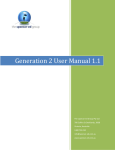
2.3 System Components
The illustration below indicates the relevant connections for the SmartLink Receiver (SCU)
installation.
4). Hardwired
1). System Data
Alarm Inputs
Connection
5). Relay Output
(C, NO, NC)
2). Telephone Line
Connection
3). Power Supply (12VDC
500mA Plug Pack)
1) System Data Connection
Green connector Plug cable connected to the SmartLink Receiver (SCU) via the DB25 connector
on the Serial Extender Card (Port 1 on the 4 Port Card).
Wiring instructions: Connect Pin 1 (Green socket connector) to Pin 2 (DB25)
Connect Pin 2 (Green socket connector) to Pin 3 (DB25)
Connect Pin 3 (Green socket connector) to Pin 7 (DB25)
2) Telephone Line Connection
Telephone line connection to existing telephone socket.
3
3) Power Supply (12VDC 500mA Plug Pack)
Once the data and telephone connections have been made, plug the 12VDC-plug pack in to a
power outlet. The SmartLink Receiver (SCU) requires at least 12VDC “Regulated” 500mApower source to operate (center pin +ve).
4) Hardwired Alarm Inputs
16 hardwired alarm inputs are supplied via a row of standard screw terminal connectors on the
SmartLink Receiver (SCU). These alarm inputs are used to monitor external hardwired alarms
such as BMS, Security, Fire, Nurse Call and other miscellaneous hardwired alarm inputs.
• These 16 channels have fixed Client ID codes built in, starting from 9901 to 9916 respectively
• Client ID 9915 represents system AC Power Failure and Client ID 9916 represents system
Low Battery (used for monitoring Supply Power to system if required)
• An Alarm is generated when the input to the connector’s “common n” and “TB n” is Closed*
• A Restore is generated when the input to the connector’s “common n” and “TB n” is Opened*
*Where n represents the channel number (1 to 16)
5) Relay Output (C, NO, NC)
The single Relay Output is used to provide an external output for interfacing third party systems.
The Relay Output is controlled by the computer, which incorporates a communications
“Watchdog” system. The relay is in the normally closed position when communication is
established with the computer and will change state when communication is lost.
Note: SmartLink Software also has an extra "Watchdog" circuit facility incorporated where if communication is lost
to the SmartLink Receiver (SCU), the SmartLink Software will automatically page the service pager of the fault.
2.4 LED Status
LED Number
1
2
3
4
5
6
7
8
9
LED Colors
Red
Red
Red
Red
Red
Yellow
Yellow
Green
Green
LED Status
NA
NA
Fast Flashing
Fast Flashing
Slow Flashing
ON
NA
ON
NA
Event Meanings
NA
NA
PC Communication
PC Communication
Modem On
Incoming Alarm
NA
Communication Failure
NA
Note: Both LED 3 and 4
rapidly flash when
communication is established
2.5 Additional Notes
• When making or changing connections to SmartLink Receiver (SCU), check that the
SmartLink Receiver (SCU) is OFF by disconnecting the plug pack from the power outlet.
• Do not change any settings on the SmartLink Receiver (SCU). This has already been
configured and defaulted by the SmartLink Engineers.
• For SmartLink-4 Software – DIP switch SW1 (inside the SCU) should have switches 1 &
5 ON and all other switches OFF. The four jumpers (LK7, LK8, LK5, LK6) near the
System Data Connector (3-wire green terminal socket) should be set to RS232 Mode .
• For SmartLink-NT Software – DIP switch SW1 (inside the SCU) should have switch 5
ON and all other switches OFF. The four jumpers (LK7, LK8, LK5, LK6) near the
System Data Connector (3-wire green terminal socket) should be set to RS232 Mode (If
more than 1 SmartLink Receiver (SCU) is used (up to 16 maximum) an RS232 to RS485
converter is required (product number RS232).
4
3. SOFTWARE INSTALLATION & SETUP
3.1 Equipment List
•
•
•
•
SmartLink-4 Software Installation Disk
Installation & User Manual
Dongle
4-Port Serial Card
3.2 Software Overview
The SmartLink-4 Monitoring Software represents the most advanced computer-based, on-site
and remote monitoring paging platforms available in the world today.
• Monitors ADEMCO High Speed, Expanded and Contact ID formats
• Automatic reporting and notification of a failure of Exception Reports
• On-Site (POCSAG) and Wide Area (PET/TAP) Paging
• Dynamic pager and group management, automatic workload management for groups
• Reminder Messages and Booked Calls
• Automatic System Failure Communication (Watchdog Paging)
• Rostering system allowing the SmartLink-4 Software to contact various staff groups
depending on the source and time an alarm has occurred
• A multitude of High Level Interfaces is available, including Fire, Security, Nursecall,
Duress, Poker Machines and Care Packages
3.3 System Requirements
•
•
•
•
•
Minimum Pentium 120MHZ CPU with 32MB of RAM and 250MB of hard disk space
Capable of running MS-DOS or Windows MS-DOS Mode (i.e. shut down Windows and
restart in MS-DOS Mode, NOT a MS-DOS Prompt running within Windows).
At least one spare ISA Slot on the motherboard for the 4-Port Serial Card. Computers
that only have PCI and AGP slots on the motherboard will NOT be compatible with the
4-Port Serial Card.
Ensure that IRQ5 is free and NOT used by another device (eg. Internal Modem Card,
Sound Card, Network Card or any other cards that may interfere with the Serial Extender
Card which uses IRQ5).
SmartLink-4 Software relies on serial communications . Ensure that both primary serial
ports (COM1 and COM2) are available. (Note that USB Ports are NOT compatible
with the SmartLink-4 Monitoring Software!)
3.4 Installation Procedure
1) Insert the SmartLink-4 Software Floppy Disk into the Floppy Disk Drive.
2) Type a:\install followed by the Enter key.
3) Follow the instructions on the screen:
a) SmartLink v4.13 Installation: press the Enter key to continue.
5
b) SmartLink Registration: Requesting you to type in Owner's Name , Company Name
and Address. Press the F10 Key to continue.
c) SmartLink Power Up: Press the Y key (for Yes) followed by the F10 key to continue
if you would like SmartLink-4 to load automatically on boot-up of the PC. To install
without this feature choose N (for No).
d) Once the SmartLink-4 Software installation is complete (takes approximately two
minutes) press the Enter key to continue before removing the SmartLink-4 Software
Disk.
4) Connect the Dongle on the Printer (Parallel) Port of your computer then re-boot to start the
Smartlink-4 Monitoring Software for the first time.
3.5 Running the Software
Note: If at the time of installation you chose to have the Smartlink-4 automatically load on boot-up please
ignore this section.
For manually loading Smartlink-4 from MS-DOS do the following:
• Type C:\SMARTLNK\SMARTLNK(space)SAVER (Note: SMARTLINK without the letter I)
at the MS-DOS prompt followed by the Enter key.
3.6 User Access Level
In order to setup SmartLink-4 you must be in Maintenance Access Level:
1) Press the F5 key from the Main Screen (while no other screens are displayed). You will be
presented with the Select Level of User Operation dialog box.
2) Use the Up and Down Arrow keys to highlight Maintenance Access and press the Enter
key.
3) SmartLink-4 will now requesting you for the Password Authorization. Type in POWER or
MAINTENANCE and press the Enter key to gain Maintenance Access Level privileges.
3.7 SmartLink Receiver (SCU) Setup
1) From the Main Screen, go to Maintenance, then System Configuration, then Port and press
the Enter key.
2) You will now be presented with the relevant Port Configuration Screen. Select any
available port (normally SCU is set to Port 1) and press the Enter key twice. Make sure that
the Receiver (SCU) is connected to the appropriate port (e.g. port 1) and that the power is on.
3) You will then be provided with a field listing a variety of Configurations . Use the Up and
Down arrow keys to highlight SMARTLINK and press the Enter key.
4) Type in a name for the new interface (e.g. SMARTLINK SCU).
5) Use the Up and Down Arrow keys to highlight the Baud Rate option and press the Enter
key. Then use the Up and Down Arrow keys to highlight 1200 Baud and press the Enter
key. Ensure that the data settings are Data 8, Stop Bits 1 and Parity None .
6) Press the F10 key to save the settings followed by the ESC key twice to complete the
Smartlink Receiver (SCU) installation and return to the Main Screen.
Note: This process must be repeated for multiple SmartLink Receivers (i.e. you can only use one
SmartLink Receiver (SCU) per Port).
6
3.8 On Site Paging Setup
1) From the Main Screen, go to Maintenance, then System Configuration, then Port and
press the Enter key.
2) You will now be presented with the relevant Port Configuration Screen. Select any
available port (normally a Transmitter is set to Port 2) and press the Enter key twice.
Make sure that the Paging Transmitter is connected to the appropriate port (e.g. port 2 of
the 4-Port Serial Card) and that the antenna is connected and the power is on (failing to
connect the Antenna while transmitting can damage the Transmitter).
3) You will then be provided with a field listing a variety of Configurations . Use the Up
and Down arrow keys to highlight POCSAG OUTPUT and press the Enter key.
4) Type in a name for the new interface (e.g. LOCAL TRANSMITTER).
5) Ensure the configuration is set to EXCLUSIVE for a single local transmitter (select
NON-EXCLUSIVE if the Smartlink-4 system is intended to control multiple
Transmitters and there is the possibility that they may transmit simultaneously).
6) Press the F10 key to save settings and press the ESC key twice to complete the On Site
Paging installation and return to the Main Screen.
Note: To Add/Modify Pager Details, refer to Section 3.11 Pager (or Mobile Phone) Details Setup.
Transmitter Types Setup
Go to Maintenance, then System Configuration, then System and press the Enter key, for a:
• 2 Watt Transmitter select Invert using the Space Bar key
• 4 Watt Transmitter select Normal using the Space Bar key
• 5 Watt Transmitter select Normal using the Space Bar key
3.9 Wide Area Paging Setup
To setup a Wide Area Paging service you will require a variety of information such as Phone Number,
Password and Serial Data Format (baud rate, data bits, stop/start bits & parity). This information should
be provided by your RCC (Radio Common Carrier). For more information, press the F1 Key (online
Help Tutorial) and choose Topic RCC Configuration.
1) From the Main Screen, go to Maintenance, then System Configuration, then Port and press
the Enter key.
2) You will now be presented with the relevant Port Configuration Screen. Select any
available port (normally Wide Area Paging is set to Port 3) and press the Enter key twice.
Ensure that the modem is connected to the appropriate port (e.g. port 3 of the 4-Port Serial
Card) and that the power is on.
3) You will then be provided with a field listing a variety of Configurations . Use the Up and
Down arrow keys to highlight TAP OUT DIAL UP and press the Enter key.
4) Type in a name for the new interface (e.g. WIDE AREA PAGING).
5) Use the Up and Down arrow keys to change the baud rate. Modems are normally set at
Baud Rate of 1200 with Data 8, Stop Bits 1 and Parity None .
6) Set the Protocol to PET 1, Message Length to 100 and Messages to 10.
7) Press the F10 key to save settings and press ESC Key twice to return to the Main Screen.
8) Main Screen, Go to Maintenance, System Configuration, RCC and press the Enter Key.
7
9) With RCC 1 highlighted, press the Enter key and enter the data provided by your RCC into
the appropriate field. Repeat this process if you have more then one RCC (SmartLink-4 can
handle up to 32 RCCs) by selecting the next available RCC.
10) Press the F10 key to save these settings and press the ESC key twice to complete the
installation of the Wide Area Paging and return to the Main Screen.
Note: To Add/Modify Pager (or Mobile Phone) Details, refer to Section 3.11 – Pager (or Mobile Phone)
Details Setup .
3.10 Clients Setup
Adding a Client
1) From the Main Screen, go to Maintenance, then Alarm Configuration, then High Level
and press the Enter key (alternatively from the Main Screen, go to Maintenance, then
Interfaces and press the Enter key).
2) You will now be presented with the High Level Interfaces menu. Choose the port associated
with the SmartLink SCU (normally Port 1 of the 4-Port Serial Card), and then press the
Enter key.
3) Use the Up and Down Arrow keys to select Add New Client and press the Enter key.
4) You will now be presented with the View Client Details screen:
Note: Additional information (eg Medical history ect..) may be added to a client’s records later by
viewing full client alarm details and pressing the ‘S’ key. (See Listing Clients for more details).
a) CLIENT (Client's Name) - enter in the brackets and press the Enter key.
b) CODE (Client ID Code) - allows you to enter in a Four Digit ID Code that has been
assigned to the Client (SmartLink unit). If you enter in an ID Code that is already in use,
you will be presented with a screen telling you that another client is presently using the
user ID. You will then be given an option to either overwrite the client's record, or view
the client's record that is using that ID. If you want to do neither, choose Cancel. If you
choose to view the client's record then you will be presented with the client's details,
which you can modify if you choose. If you do not wish to modify these details press the
F10 key or the Esc key to go back to the SmartLink High Level Interfaces menu. If you
need to use an ID Code that is already in use, contact the System Administration.
Note: If you choose to overwrite the client's record, all of the client's details will be lost.
c) STATUS (Client's Status) - press the Enter key to show a Sub Menu of ABSENT or
PRESENT. This function allows you to keep track of field units Self Test facilities. If a
unit is present, yet there has been no test report detected by the SmartLink-4 Software for
a programmed period of time (1 to 30 Days), then the SmartLink-4 Software will
automatically generate a Self Test alarm and notify the relevant personnel. Choose either
PRESENT (enable test reports) or ABSENT (Disable test reports) using the Up and
Down Arrow keys followed by the Enter key to select your choice.
d) ADDRESS (Client's Address) – There are three lines that can be used for the Clients
Address. Your cursor will start the first line of the address bracket and as you enter data
followed by the Enter key, the curser will automatically go to the next line.
8
e) SELF TEST (Self Test Function) - prevents the scenario of a field unit malfunction
going unnoticed. The Self Test function means that a client's alarm must call the
SmartLink-4 Software periodically to demonstrate that it is still working. If this is a
desired feature add a number between 1 and 30 to define the time period in days (e.g. if a
value of 20 is entered into Mrs Jone's Self Test value, then Mrs Jone's SmartLink MediCall unit has up to 20 days to dial in before a Self Test Failure alarm will occur notifying
that the unit is not operating as correctly)
Note: If a client is entered as ABSENT, no Self Test will occur, however, all other alarms will
operate as normal.
f) PHONE (Client's Telephone Number) - enter the Client's Telephone Number and press
the Enter key.
g) ROSTER (For Automatic Paging) – the SmartLink-4 Software can handle up to 99
Rosters, which are displayed in the Sub Menu. These Roasters can be assigned to clients
to define who should be paged. Appropriate Roasters can depend on location to the client
or by shift work etc. For example, when the alarm is activated for a certain client you
may wish to have the closest person paged. If Mrs Jone's room is in the North Wing, then
the designated person for the North Wing should be paged, not someone in the South
Wing. For SmartLink-4 Software to determine who should be paged, you will need to
select a roster. When an alarm goes off, the SmartLink-4 Software will look up which
roster the client has been assigned along with the time and whether it is a weekday or a
weekend. The software will then automatically page the appropriate person. Refer to
section 3.12 Rosters Setup .
To enter in a Roster, press the Enter Key again to show the Sub Menu. Choose the
relevant Roster by using the Up and Down Arrow keys for that client and press the
Enter key.
Note: Always choose or enter a Roster (e.g. ROSTER #1) even if no Rosters are required.
h) CONTACT (Client's Contacts) - allows you to enter details of the client's contacts in case
of an emergency such as next of kin. Enter in the first contact's name in the first bracket
and press the Enter key, followed by Phone bracket and Relationship bracket (a list of
options for Relationship can be brought up by pressing the Enter key). Repeat this
process for all appropriate Contacts. If you only wish to enter one contact, repeatedly
press the Down Arrow key instead of the Enter key until you have reached the first
ALARMS bracket.
i) ALARMS (Alarm Descriptions) - allows you to enter your own descriptions for 8
different alarms (referred to as zones). These could be panic button, inactivity, smoke
detector, bedroom, call point, etc. In the event that an alarm is activated, the SmartLink-4
Software Setup will show exactly which zone has set off the alarm, and what type of
alarm it is. If zone 1 is breached, next to that bracket a FLASHING bar will come up
describing the urgency/severity of the alarm (i.e. whether it is an Emergency or the alarm
has a Low Battery etc). At the top of the screen, next to 'EVENT', it will show what type
of alarm it is (i.e. if it is a duress call, zone trouble etc). To enter in a description of an
alarm, type in the description in the first bracket and press the Enter key. Repeat this
process for all required zones to enter their individual descriptions.
5) Press the F10 key to save, then choose OK and press the Enter key to conclude the entering
of the Client's Details.
9
Listing Clients
Highlight List Clients from the High Level Interface menu and press the Enter key. You will
be presented with a list of Client Names and ID Codes. You can scroll through this list by using
the Up and Down Arrow keys and using the Enter key to select. Press the ESC key to exit this
function.
When viewing a client, either in the Client List or under Display Active Alarms, press the ‘S’
key to bring up the Review Client Statistics window. This can now be used to store additional
notes and provide further statistical information if required. NB: Press the F10 key to save
entered information.
Editing Clients
Highlight Edit Clients in the High Level Interface menu and press the Enter key. You will be
presented with a list of Client Names and ID Codes. Using the UP and Down Arrow keys to
highlight the Client that you wish to Edit/Modify and press the Enter key to select. Edit the
appropriate fields as described in Adding a New Client. Press the F10 key to save, choose OK
and press the Enter key to finish modifying/editing a Client's Details.
Removing Clients
Highlight Remove Clients in the High Level Interface and press the Enter key. You will be
presented with a list of Client Names and ID Codes. Use the UP and Down Arrow keys to
highlight the Client that you wish to Remove/Delete and press the Enter key. You will now be
asked if you are sure. Choose OK and press the Enter key to Remove/Delete that client from the
list.
Viewing Responses
This function allows you to review whether a Client's Med-Call Unit has called in to the
SmartLink-4 Monitoring Software during the designated time span. To view this function,
highlight View Responses from the High Level Interfaces menu then press the Enter key.
Press the Enter key again to view a list of the Client Names and ID Codes that have not called
in. You can then select a client by using the Up and Down Arrow keys and press the Enter key
to bring up the Clients Details if you wish to take further action. Otherwise you can ring any
relevant Contacts or Clients displayed on the right hand side of the screen. Press the ESC key to
return to the High Level Interfaces menu.
Setting up ADEMCO
The Setup Ademco function allows you to change the alarm names and system names that
appear in the SmartLink-4 Software. This means you can change the descriptions to suite your
own company’s needs and preferences. The alarm name indicates the status of the alarm zone,
whether everything is normal or if the alarm is activating. The system name indicates the type of
alarm, whether it is for zone trouble, duress etc. By changing the names of the alarms and
systems in the Setup Ademco option, you are making a global change throughout the
SmartLink-4 Software. For example, if you were to change the System name Duress, to read
Code Red, every time a duress occurs, SmartLink-4 Software will display Code Red, not Duress.
Highlight Setup Ademco from the menu and press the Enter key. Use the Up and Down Arrow
keys to highlight the alarm or system name you wish to change and system names and press the
F10 key to return to the High Level Interfaces menu.
WARNING: This should only be used when customising of alarm types is required. The
default alarm names are based on a standard that will suit the majority of installations.
10
3.11 Pager (or Mobile Phone) Details Setup
1) From the Main Screen, go to Modify, then Pager Details and press the Enter key.
2) Enter a name for the pager (eg ADMINISTRATION 1) and press the Enter key.
3) Enter the Pager Capcode (e.g. 1234567) Normally this is the last 7 Digits of the Pager or
Mobile Phone Number.
4) Enter the PBX Number (used for PABX Communications and default the next available
number).
5) Use the Up and Down Arrow keys to select the Pager Type , then press the Enter key. Use
the Up and Down Arrow keys to select TONE ONLY PAGER, NUMERIC PAGER or
ALPHANUMERIC PAGER.
6) Press the Enter key twice and select the Network Type . Use the Up and Down Arrow keys
to select TRANSMITER or WIDE AREA PAGING and press the Enter key.
7) For most situations the Require time and date stamps , Require message stamps and
Require automatic logging options should be activated. Use the Left and Right Arrow
keys to change these options between YES (activated) and NO (deactivated).
8) Press the F10 key to save settings and then press the ESC key to return to the Main Screen to
complete setting up the Pager (or Mobile Phone) Details.
Modifying Pager (or Mobile Phone) Details
Press the TAB key in the Pager Name field to display the list of pagers installed in the
SmartLink-4 database. If no list appears then no pagers are setup in your database. Use the Up
and Down Arrow keys to highlight the pager you wish to modify, then press the Enter key. The
Pager Details screen will update to reflect the change. If you make any changes, press the F10
key to save followed by the ESC key to exit to the Main Screen.
Removing Pager (or Mobile Phone) Details
Use the Up and Down Arrow keys to highlight the pager you wish to remove and press the
Enter key to select. Alternatively press the Insert key to tick off a number of pagers that you
wish to delete, and then press the F10 key when you have completed your selection. SmartLink4 will prompt you for confirmation before deleting any pagers in the database. Select OK and
press the Enter key to proceed, or choose CANCEL if you don't want to remove the pagers.
Press the ESC key to return to the Main Screen.
Note: Pressing the F1 key while viewing the pager details setup will bring up the Online Help Tutorial
that will provide addition information on the topic of Installing/Modifying Pager Details.
3.12 Rosters Setup
Note: Pager (or Mobile Phone) Details must be entered in first before Rosters can be Setup. Refer to
Section 3.11 Pager (or Mobile Phone) Details Setup. For Automatic Paging, the Roster must also be
enabled (selected) in the Clients Setup. Refer to Section 3.10 Clients Setup (Adding a Client).
Automatic Paging
1) From the Main Screen, go to Maintenance, then Alarm Configuration, then Rosters and
press the Enter key.
2) You will now be presented with the Alarm Roster Schedule Configuration screen with
ROSTER #1 highlighted.
3) Press the Enter key or use the Up and Down Arrow keys to select a ROSTER (between 1
and 99). Note that the Roster names can be changed or left as default (e.g. ROSTER #1).
11
4) Use the Up and Down Arrow keys to highlight Weekday Operation. Enter in a time based
on a 24-hour clock (i.e. 00:01 to 23:59) and press the Enter key. You will now be presented
with a Sub Menu. Use the Up and Down Arrow keys to select pager/mobile phone for
Automatic Paging and press the Enter key. Note that you can use up to four roster shifts to
select whom you wish to receive alarm call messages at different times of the day.
5) Press the F8 key to toggle Weekend Operation and repeat the same precudure in the
previous step.
6) Press the F10 key to save and press the ESC key twice to complete setting up the Rosters
and exit to the Main Screen
Note: Pressing the F1 key while viewing the pager details setup will bring up the Online Help Tutorial
that will provide addition information on the topic of Defining Roster Schedules.
3.13 Group Details Setup
Note: Pager (or Mobile Phone) Details must be entered in first before Rosters can be Setup. Refer to
Section 3.11 Pager (or Mobile Phone) Details Setup.
1) From the Main Screen, go to Modify, then Group Details and press the Enter key.
2) You will now be presented with the Group Details screen with your cursor highlighting the
Enter Group Name option.
3) Type in a Group Name (e.g. North Wing Group) and press the Enter key.
4) Enter a PBX Number (used for PABX Communications and default to the next available
number).
5) The Rotary Group Calling is used to distribute workload among staff and is set to NO as
default.
6) The Require Time and Date Stamp can be changed using the Left and Right Arrow keys
and is set to No as default.
7) The Require Automatic Logging is used to generate reports at a later point in time and is set
to Yes as default.
8) Press the F10 key to save and press the ESC key to complete the Group Details Setup and
return to the Main Screen.
Note: Pressing the F1 key while viewing the pager details setup will bring up the Online Help Tutorial
that will provide addition information on the topic of Installing/Modifying Group Details.
12
4. SOFTWARE USER MANUAL
4.1 Introduction
The SmartLink-4 Monitoring Software is designed to notify people when an alarm is activated,
give details of that alarm and whom to contact (refer to Section 3.10 Clients Setup (Adding a
Client). To use these functions you will need to enter client and alarm details into the programs
client database. Details you will need to provide are:
• Client Name
• Client Code (a four digit ID code for Client reference)
• Whether the client is absent or present (for auto-test reports)
• Client Address
• Self Test (Default 7 Days)
• Client Telephone Number
• Roster
• Contact (Whom to Contact in case of an alarm)
• Alarms (8 different alarm zone descriptions)
A message is sent to the SmartLink-4 Software from the SCU receiver for the following:
• Client Alarms
• Opening Reports
• Closing Reports
• Zone Exclusions
• Zone Trouble
• System Alarms
• Self Tests (failure to test)
4.2 Running the Software
Note: If at the time of installation you chose to have the Smartlink-4 Software automatically load on bootup please ignore this section.
For manually loading Smartlink-4 from MD-DOS do the following:
• Type C:\SMARTLNK\SMARTLNK(space)SAVER (Note SMARTLINK without the letter I)
at the MS-DOS prompt followed by the Enter key.
4.3 Exiting the Software
To quit and exit to MS-DOS simply:
1) Press the ESC key from the Main Screen (while no other screens are displayed). You will be
presented with the Password Authorization dialog box requesting you for the Maintenance
Password to exit SmartLink-4 Software
2) Type in MAINTENANCE or POWER and press the Enter key. The SmartLink-4 Software
will prompt you for confirmation before exiting. Select OK and press the Enter key to
proceed, or CANCEL if you don't want to exit (alternatively press the ESC key to return to
the Main Screen).
13
4.4 Quick Reference Keys
Help / Tutorial (F1)
Online help is provided in two forms:
1) From the Main Menu, press the F1 key to bring up the Context Sensitive Online
Help Reference screen. Use the Up and Down Arrow keys to Scroll through the
current topic and use the Left and Right Arrow keys followed by the Enter key to
select Next or Previous (to browse through topics one at a time), Topics (to provide a
full listing) or Exit (to Main Screen).
2) From the Current Screen, press the F1 key to display a brief description of the
current window, menu option or entry field.
Enable Screen Saver (F3)
Press the F3 key to leave a Screen Saver indicating whether the SmartLink-4 software is
currently in Staffed or Away mode of operation.
Change Level of Access - Operator, Administration, Maintenance (F5)
SmartLink-4 operations are divided into three distinct levels of accessibility. Each level
provides additional features and operations. Users can change between Access Levels,
with the higher access levels providing more complicated facilities.
1) From the Main Screen, press the F5 Key to display the logon Screen.
2) Use the Up and Down Arrow keys to Select level of User Operation.
Operator – Allows manual paging, messaging, status of alarms and some statistical
analysis. No password is required.
Administration – Access to Maintenance Databases to edit Clients, Rosters, for
keeping backups and monitoring System Reports. The default Password is
Administration.
Maintenance – for installation and setup of SmartLink-4 Hardware and other
restricted Database features and configurations. The default Password is
Maintenance.
3) To return to the most restricted level of access, press the F5 key, select Operator
Access and press the Enter key (note that no password is required for this).
Toggle Staffed or Away (F6)
Toggling the F6 key will switch SmartLink-4 between STAFFED and AWAY modes.
STAFFED - Monitoring Centre must process incoming alarms by pressing the Enter
key. Computer speaker beeps are enabled.
AWAY - alarms are automatically process and computer speaker beeps are disabled.
Display Last Alarm (F8)
Press the F8 key to display the last incoming alarm.
Display Version Information (Shift + TAB)
The Version Information or ‘About’ screen displays the SmartLink-4 Version Number,
Copyright, and Memory Available etc. and can be viewed by holding down the Shift key
and pressing the TAB key at the same time.
14
4.5 Reviewing Active Alarms
This facility allows you to view all the currently active alarm inputs on the system. Each alarm
input will display information about the alarm such as its name, how long it has been activated
for, whether or not it is urgent and who is currently being contacted.
Note: Pressing the F1 key will bring up the Online Help Tutorial that will provide addition information
on this topic.
1) From the Main Screen, go to Display, then Active Alarms and press the Enter key.
2) You will now be presented with the Reviewing Active Alarms screen. Use the Up and
Down Arrow keys to find an active alarm and press the Enter key (or the Page Up and Page
Down keys to select the relevant Alarm Screen).
3) Press the ESC key twice to exit to the Main Screen.
4.6 Status Symbols
There are 4 symbols in the top right hand corner of the SmartLink-4 Main Screen that provide
real time updates on message activity. The three left most dots indicate the progress of TNPP,
Wide Area and Local Area (On Site) messages respectively. The dots are Red if there are
messages waiting to be sent; otherwise they are Green.
The last icon is a musical symbol that represents the status of the Local Area (On Site)
Transmitter. A single Red flash of the musical symbol indicates that the Transmitter is sending a
message; a Green musical symbol indicates that the Transmitter is idle and a permanent Red
musical symbol means that it cannot transmit due to interference.
4.7 Manual Paging
The simplest way of sending messages in SmartLink-4 is to use a Manual Page. Simply select
the people you wish to contact, type in the message, and then send the message. SmartLink-4
takes care of the rest.
Manual Keyboard paging allows you to effectively contact key personnel quickly and efficiently.
You have the ability to contact any number of personnel simultaneously by simply selecting
them from an alphabetically sorted list of pagers, mobile phones and group names.
1) From the Main Screen, Go to Manual Page and press the Enter key. You will now be
presented with the Manual Page screen.
2) Press either the TAB key or Enter key and you will be presented with a list of pager names.
3) Use the Up and Down Arrow keys to highlight the pager that you wish to page and press the
Enter key.
4) Type in the Alphanumeric message you wish to send to the Alphanumeric Pagers/Mobile
Phones or the Numeric message you wish to send to specific Numeric Pagers.
5) Press the F10 key to send the message.
6) Press the ESC key to exit and return to Main Screen.
Note: Pressing the F1 key will bring up the Online Help Tutorial that will provide addition information
on this topic.
15
4.8 Surveying Sites
It is a good idea to test the coverage of your local area Transmitter. If you use The Survey Site
screen to send periodic test messages then you can roam around the installation site with a test
pager.
Thick steel and concrete, large magnetic and electric fields, and terrain and weather conditions
will affect Transmitter efficiency. When you perform a site survey you should pay particular
attention to the quality of the messages that you receive on the test pager. If you receive
corrupted messages then it is possible that you will have problems sending messages to that
particular region.
The Survey Site screen is a useful tool for testing coverage of your transmitter. All you do is
send out a test message periodically, and then walk around looking for trouble spots.
Note: Pressing the F1 key will bring up the Online Help Tutorial that will provide addition information
on this topic.
•
•
•
•
•
Select Survey Pager/Group
Specify Time Interval
Exit Site Survey
ACTIVATE/DE-ACTIVATE Site Survey
ADTIVATE/DE-ACTIVATE Test Mode
1) From the Main Screen, go to Maintenance, then System Configuration, then Survey and
press the Enter key. You will now be presented with Survey Site screen.
2) Press the Enter key and you will be presented with a list of pager names.
3) Use the Up and Down Arrow keys to highlight the pager that you wish to send test messages
to and press the Enter key.
4) Specify the Timer Interval (set to a default of 60 seconds).
5) Use the Up and Down Arrow keys to highlight ACTIVATE Site Survey and press the
Enter key to begin surveying.
6) When finished testing, press Enter key again to DE-ACTIVATE Site Survey.
7) Highlight Exit Site Survey and press the Enter key, then highlight Exit and press the Enter
key again to return to the Main Menu.
4.9 Reviewing the System Status
This facility provides you with important summary information concerning the status of your
system such as Installation details, Hardware details, Alarm details and Call details etc. All of
these details are updated in 'REAL TIME' to give a true indication of what is occurring.
Note: Pressing the F1 key will bring up the Online Help Tutorial that will provide addition information
on this topic.
•
•
•
•
•
Build/Version Info
Pager/Group Summary
Hardware Summary
Port Summary
PBX Summary
•
•
•
•
Transmitter Summary
Call Summary
Network Summary
Exit
1) From the Main Screen, go to Display then System Status and press the Enter Key. You will
now be presented with the System Status screen.
2) Use the Up and Down Arrow keys to highlight the topic you wish to summarize and use the
Page Up or Page Down keys to summarize the relevant page.
3) Highlight Exit and press the Enter or ESC key return to Main Screen when complete.
16
4.10 Using the Report Summary
Graph Top Callers (Graphing The Top Callers)
This displays the fifteen most frequently paged people and the fifteen top people who have not
responded to alarm activation within the designated time period.
The graphical representation of the top callers takes place in a horizontal graph, where the most
frequently called person is displayed at the top and the fifteenth most frequently called person is
displayed at the bottom of the graph.
This facility updates in real time so that any calls being made elsewhere on the system will be
automatically reflected in the graphical representation of the top callers (if applicable). As the
number of calls per person increases, the horizontal axis representing the number of calls made
will automatically adjust to suit the largest number of calls made.
Call Statistics (Call Rate Statistics)
This is by far one of the most important facilities provided by the SmartLink-4 package with
respect to administration. This facility allows you to review the call rates on a per day basis
within a year with a further break down of the calls made for a particular day on an hourly basis.
This facility allows you as an administrator to analyze call trends over days, weeks, months and
even a complete year. You also have the ability to view at a glance the average number of calls
for the year as well as on an hourly basis. This will allow you to adjust staffing levels according
to peak and low periods on a per day basis, based on the daily average or alternatively, on a
weekly basis for holiday periods.
Further to this you can also cross tabulate any particular period with the actual calls being sent
out via the paging system using the Report Wizard.
Report Wizard (Generating Your Own Reports)
By far the most important aspect of the system is the ability to produce a report on any aspect of
the system. This facility is known as the Report Wizard. This allows you to produce your own
custom designed reports from the history of the calls made on the system. (e.g. a report could be
generated for all calls sent to Joseph Banks between a certain time and date generated by the
Pressure Valve #10 alarm being activated).
This is by far the most powerful report generator available for any paging product to date.
Normally you would have to generate the report yourself by exhaustively searching through the
stored logs. This not only consumes large amounts of human resources but also the Paging
System would be unavailable for this time.
With SmartLink, you can simply specify the report that you want to generate and the Report
Wizard will search the stored logs and produce the report either to be displayed on the screen,
printed or saved for later retrieval and at the same time not sacrificing any of your time or the
system's time.
Viewing Reports (Viewing a Previously Saved Report)
As described earlier, you have the ability to generate your own custom made reports around any
aspect of the system based on the stored logs. As an administrator, you may wish to save these
newly generated reports for future reference. If so, by using this facility you have the ability to
load and view these reports at any time in the future, and if necessary, print them out.
17
Print Reports (Printing Reports)
A very important part for any Paging System is the ability to print out reports on various aspects
of the system for future reference. SmartLink-4 allows you to print out various standard reports
to assist you with administration and maintenance. These reports provide an invaluable 'hard
copy' of your system details and more importantly the SmartLink-4 Software reporting
capabilities can also allow for these reports to be even further refined. This will give you the
ability to print out specific 'parts' of a report and set how many copies that you wish to print.
4.11 Using File Management
From time to time, the system administrator may require maintenance in the form of backing up
to restore the system database, as well as clearing the transaction log. This is a very simple task
and requires very little time and user interaction. It provides security for your system in the event
of computer failure as well as the ability to back up the 'history' of your system for
administration purposes. Such a task may be performed on a weekly, monthly or yearly basis.
Note: Pressing the F1 key will bring up the Online Help Tutorial that will provide addition information
on this topic.
1) From the Main Screen, go to Maintenance, then File Management and press the Enter key.
You will now be presented with the SmartLink File Management screen.
2) Use the Up and Down Arrow keys to highlight the desired topic and press the Enter key.
• Backup - Backup System Files to Floppy Disk or Hard Disk
• Restore - Restore System Files from Floppy Disk or Hard Disk
• Clear Log - Clear the existing Transaction Log
• Clear System - Clear the System Transaction Log
• Export Call Data - Export Client Call Data
• Exit - Exit the Backup/Restore Facility and return to the Main Menu screen
4.12 Entering Test Data Strings
1) Hold down the Control key and press the Print Screen key.
2) Enter the data defining the type of alarm followed by the Enter key.
An appropriate data string contains a 4-digit client code followed by 8-digits of channel data (or
zones) and a type identifier as follows:
[client code] [channel data] [type identifier]
For example: 1111551555557
Where: 1111 is the client code,
55155555 is the channel data, and
7 is the type identifier
Pressing the S key when an alarm is visible on the screen will bring up additional notes and
statistics associated with that particular alarm.
If an alarm is already on the screen and a new alarm is generated, the screen will display ‘new
alarm's pending’ and identifies the first alarm by name and the total number of other alarms
pending in queue.
18
The following examples display typical communications between a SmartLink and its
monitoring terminal (and radio pagers) as listed below:
a)
b)
c)
d)
e)
1111
1111
1111
1111
1111
15555555
35555555
51555555
53555555
55555555
7
7
7
7
7
f)
g)
h)
i)
j)
k)
1111
1111
1111
1111
1111
1111
55555555
15555555
35555555
51555555
11555555
15555555
9
6
6
6
6
7
l)
m)
n)
o)
p)
q)
r)
1111
1111
1111
1111
1111
1111
1111
85555555
15555555
35555555
55555555
15555555
55555555
15555555
7
1
1
2
3
4
5
Send an alarm on zone 1
Send a "restoral" or cancel the zone 1 alarm
Send an alarm on zone 2
Send a "restoral" or cancel the zone 2 alarm
Send a "manual test call" ("Cancel" button pressed without a
previous alarm)
Send an "auto-test call"
A power failure has occurred
Power is restored
Battery is low and approaching its cut off threshold point
Power fail & low battery (Battery may need replacing)
Person attending a previous alarm on zone 1 needs urgent
assistance
Alarm on zone 1 and pendant (transmitter) has a low battery
Duress (Emergency) panic
Duress is restored
System switched off (opening)
Zone 1 has been isolated or bypassed
System switched on (closing)
Trouble alarm on zone 1 (Low battery on device)
Note: The above examples use a test client code 1111
© Copyright SmartLink International Pty Ltd
August 2001
Email: [email protected]
Web Site: www.smartlink.com.au
To the best of our knowledge, the information contained in this manual is correct at the time of print.
SmartLink International Pty Ltd reserve the right to make changes to the features and specifications at
any time without prior notice in the course of product development.
19