1
3.2
User accessible compartment
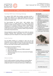
A compartment with connection blocks and swtches can be accessed by removing the lid with a tool.
Figure 2
The compartment contains the switches indicated in § 0 and:
• a 4-pole cage clammp terminal block for the two extensions;
• a 4-pole cage clamp terminal block for the S bus
• a 2-pole removable screw terminal block for the telephone line
3.3
LEDS
Two LEDS are located on the front of the device and indicate the power supply state of the NT1Plus:
−
a green LED ("230 V") indicates that the device is supplied with a.c. power.
−
a red LED ("U INTERF.") indicates that the device is connected to the telephone line and a correct voltage is received.
3.4
Switch settings
The front panel has a removable cover to access three hardware switches:
• S bus configuration (short passive / extended)
• emergency power (one of the POTS interfaces or the S0 bus)
• terminating resistors for the S bus
All other settings are made through configuration procedures.
3.4.1 Short/Extended Bus settings
Fig. 3-1 shows four possible configurations for the "S" BUS with the corresponding settings and maximum
distances permitted.
7
_