1
III
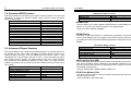
The ENDAT-7105M System Board
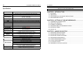
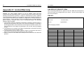
Specification:
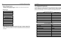
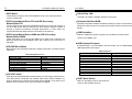
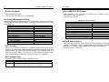
TABLE OF CONTENTS
Model
ENDAT-7105M
Form Factor
System Chipset
Mini-ITX 170 mm x 170 mm (6.69”x6.69”) with 6 layers PCB
CPU Support
Memory
Ethernet
VGA
LCD interface
Duo View
Video Interface
Serial / Parallel
RS-422/485
Watchdog Timer
IDE Connector
SATA Connector
AUDIO
Expansion Slot
Back Panel I/O
I/O on board
Digital IO
Power Supply
IV
User Manual
VIA CN700(NB/2.5W)+ VIA VT8237R Plus (SB/1.8W)
VIA Eden ULV 500MHz (1W)
VIA Eden 1.0GHz (5W)
VIA C7-D 1.5GHz (20W)
One 240Pin DDRII 533/400 DIMM up to 1GB
VT8237R Plus integrated 10/100 Fast Ethernet w/ VT6103 (PHY)
Integrated VIA UniChrome Pro 3D / 2D Graphics with SMA 16/32/64MB
LVDS:18/24/36/48 bits with LVDS Transmitter VT1636(Optional)
CRT+LCD
Integrated MPEG-2(DVD/DVB) Hardware decoder
4 Serial Port w/ +5V, +12V Power Selector / 2 Parallel port
Via COM2 (Optional)
Programmable WDT from 1 to 255 seconds / minutes by
Winbond W83697HG
1 x 40pin IDE connector support UDMA 33/66/100/133,
1 x 44pin connector support Slim type HDD
2 x 150MB/s SATA device support Raid 0, 1, JBOD
Integrated VT8237R Plus Audio controller
w/ VT1613 Audio Codec for 2 Channel output
1x 32bits PCI slot
PS/2 Keyboard / Mouse Connector
2 USB port + RJ-45 LAN Connector(10/100)
VGA, LPT1 and COM1/COM2/COM3 with D-Sub connector
Audio jack for Line-out
LVDS with 1.25mm DF13 40-pin connector
LPT2 with 2.0mm Box Header
COM4 with 2.54mm Box Header
1 IrDA TX/RX port with Pin Header
Pin Header for KB/MS, 4 x USB, CD-in, SPDIF-IN/OUT, Mic-in,
Line-in, Line-out, SM Bus, KB/MS for external device
2.0mm Pin Header for 16-bits Digital I/O with
CMOS/TTL level (8 bit input / 8 bit output)
ATX power supply
CHAPTER 1. INTRODUCTION ....................................................... 1
1-1.
1-2.
1-3.
1-4.
FEATURES .............................................................................................. 2
UNPACKING ............................................................................................ 3
ELECTROSTATIC DISCHARGE PRECAUTIONS ................................... 3
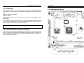
MOTHERBOARD LAYOUT ...................................................................... 4
CHAPTER 2. SETTING UP THE MOTHERBOARD ....................... 5
2-1. JUMPERS AND CONNECTORS.............................................................. 5
2-2. INSTALLING MEMORY.......................................................................... 14
2-3. SHARED VGA MEMORY ....................................................................... 14
2-4. ASSIGNING IRQs FOR EXPANSION CARDS ....................................... 14
2-5. WATCHDOG TIMER…………………………………………………………. 15
2-6. DIGITAL I/O…………………………………………………………...………. 17
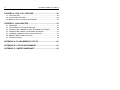
CHAPTER 3. AWARD BIOS SETUP............................................. 19
3-1. STANDARD CMOS FEATURES............................................................. 20
3-2. ADVANCED BIOS FEATURES............................................................... 21
3-3. ADVANCED CHIPSET FEATURES ........................................................ 21
3-4. INTEGRATED PERIPHERALS............................................................... 24
3-5. POWER MANAGEMENT SETUP........................................................... 27
3-6. PnP/PCI CONFIGURATIONS................................................................. 29
3-7. PC HEALTH STATUS ............................................................................. 30
3-8. FREQUENCY/VOLTAGE CONTROL ..................................................... 31