1
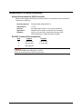
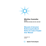
Datacolor
Datacolor 550
User’s Guide
Datacolor 550 User’s Guide (Part No. 4230-0391M, April 2005)
All efforts have been made to ensure the accuracy of the information presented in this
format. However, should any errors be detected, Datacolor appreciates your efforts to
notify us of these oversights.
Changes are periodically made to this information and are incorporated into
forthcoming versions. Datacolor reserves the right to make improvements and/or
changes in the product(s) and/or program(s) described in this material at any time.
Copyright © 1996-2004 Datacolor. ALL RIGHTS RESERVED. This material may not
be reproduced or duplicated, in whole or in part, with the express written permission of
Datacolor.
Microsoft®, MS-DOS®, and Microsoft Windows® are registered trademarks of
Microsoft Corporation. All other registered trademarks are the property of their
respective owners.
To obtain information on local agents, contact either of the offices listed below, or visit
our website at www.datacolor.com.
United States
Lawrenceville, NJ
Telephone: 1 (609) 924 2189
Fax:
1 (609) 895 7472
Switzerland
Dietlikon
Telephone: (41) 1 835 3711
Fax:
(41) 1 835 3820
Contents
Datacolor 550........................................................................................................ 1
About the Datacolor 550.................................................................................. 1
Electrical and Environmental Requirements............................................. 2
Adjustable UV Filter Option....................................................................... 2
Transmission Option ................................................................................. 2
Feature Summary ..................................................................................... 2
Accessories ..................................................................................................... 3
Calibration Tiles ........................................................................................ 4
Aperture Plates ......................................................................................... 4
Cable Installation ................................................................................................. 7
Power Cable .................................................................................................... 7
Serial Cable Installation................................................................................... 8
USB Cable Installation..................................................................................... 8
Cable Installation ...................................................................................... 9
Driver Installation ...................................................................................... 9
Changing the Instrument Port Setting in Datacolor Programs................ 11
Com Port Setting..................................................................................... 11
Installing Calibration Data ....................................................................... 12
Controls and Indicators..................................................................................... 13
Controls and Indicators Panel ....................................................................... 13
Powering Up .................................................................................................. 14
Instrument Calibration....................................................................................... 15
Reflectance Calibration ................................................................................. 15
Transmittance Calibration.............................................................................. 16
Transmission Accessories ...................................................................... 16
Sample Presentation and Measurement.......................................................... 19
Sample Presentation and Measurement Overview....................................... 19
Reflectance Measurements .................................................................... 19
Sample Viewing Port............................................................................... 20
Transmittance Measurements ................................................................ 21
Maintenance ....................................................................................................... 23
About Instrument Maintenance ..................................................................... 23
Sphere Cleaning ..................................................................................... 23
Tile Handling and Cleaning..................................................................... 24
Appendix............................................................................................................. 27
Datacolor 550 Optical Block Diagram ........................................................... 27
Instrument Specifications .............................................................................. 28
Optional Accessories..................................................................................... 29
Miscellaneous Technical Information ............................................................ 30
System Requirements for USB Connection............................................ 30
RS-232C Connector Pin Assignments.................................................... 30
Compliance Statements ................................................................................ 31
FCC Compliance Statement ................................................................... 31
Canadian Compliance Statement ........................................................... 31
Index.................................................................................................................... 33
Datacolor 550 User's Guide
Contents • i
Datacolor 550
About the Datacolor 550
The Datacolor 550 is a member of the latest generation of bench top color measuring
instruments manufactured by Datacolor, incorporating state-of-the-art CMOS integrated
circuit technology in the instrument design. It is intended for use as a device for measuring,
specifying and evaluating color in both laboratory and production settings.
Below is a summary of the standard and optional features included with the Datacolor 550.
Standard features include the following:
•
Multiple aperture sizes to accommodate samples of different sizes
•
Automated, adjustable ultra-violet filters for measuring fluorescent samples
•
Transmittance Measurement
•
Pulsed xenon light source
•
Automated specular port
•
Automated zoom lens
Datacolor 550 User's Guide
About the Datacolor 550 • 1
Electrical and Environmental Requirements
Power
85 to 264 VAC, 47 to 63 Hz, 80 VA peak, 35 VA
typical
Absolute Operating
Environment
5º to 40º C, 5-85% RH, non-condensing
Interfaces
Serial: RS232
9600/115200 baud (shipped at 19200 baud)
USB: 1.1
Adjustable UV Filter Option
This option offers the ability to control the amount of UV light emitted from the light source.
This is used for applications that need to identify the presence of optical brightening
agents, or other types of fluorescent materials in the samples being evaluated.
The configuration of the adjustable UV filter option is handled through the software. See
the Datacolor Tools User Guide for detailed instructions to configure the option and
calibrate the instrument.
Transmission Option
The 550 can measure the “regular” transmittance of transparent solid and liquid samples.
Safety Warnings
If the equipment is used in a manner not specified by the manufacturer, the protection
provided by the equipment may be impaired.
Caution: There are no user-serviceable parts for this equipment.
Light Source
Do not stare directly into the open port located in the front door panel when the
measurement is in progress. Staring directly into the light source can result in eye
discomfort similar to that of staring at a camera flash.
Power
CAUTION
Disconnect power before servicing.
NOTE
The power cord supplied with the unit must be used.
2 • About the Datacolor 550
Datacolor 550 User's Guide
Feature Summary
The Datacolor 550 employs state-of-the-art features including the spectrometer, integrating
sphere, light source, and optics. Below is a summary of those features:
FEATURE
DESCRIPTION
PURPOSE/BENEFIT
Integrating
sphere
Barium coating sphere.
Industry standard.
Measurement
Geometry
D/8º geometry, Specular
Component Included
(SCI) or excluded (SCE).
Provides for more uniform
measurement of samples with
irregular surfaces.
SP2000 Spectral
Analyzer
Proprietary dual-channel
holographic grating. 256photodiode linear arrays
used for both the
reference and sample
channels.
Dual channel design provides
continuous monitoring of sample
illumination and compensates
for changes. 256-photodiode
array enhances the precision of
the measurement.
Light source
Pulsed xenon flash lamp
Filtered to provide D65
illumination including UV
component.
Effective
Bandwidth
10nm
Reporting interval.
Accessories
All models come with the following standard accessories:
•
3 Aperture Plates
•
Black Trap
•
White Tile
•
Green Tile
•
Six foot power cable
•
Black Card
•
Serial cable with connectors on either end
•
USB Cable
Datacolor 550 User's Guide
Accessories • 3
Calibration Tiles
A black trap, white tile and green tile are provided with all Datacolor 550 instruments:
The black trap and white tile are used each time the instrument is calibrated. The green tile
is used to perform an optional diagnostic test.
Aperture Plates
Three aperture plates are included as standard accessories with the Datacolor 550. The
identification is engraved on each plate.
•
Large Area View (LAV)
•
Small Area View (SAV)
•
Ultra-Small Area View (USAV)
4 • Accessories
Datacolor 550 User's Guide
Optional Aperture Plates
•
Extra Ultra Small Area View (XUSAV)
Below are aperture plate specifications:
Aperture
Identification
Sample Area
Measured
Sample Area
Illuminated
LAV
SAV
USAV
XUSAV
26mm
5mm
2.5mm
2.5mm
30mm
9mm
6.5mm
3.0mm
NOTE
The area illuminated is always 4mm greater than the diameter measured, to reduce
translucency errors. The exception to this is the XUSAV plate.
Tips for Aperture Selection
•
Always use the largest possible aperture size.
•
The Large Area View (LAV) plate is recommended for averaging samples with
irregular surfaces and textured samples.
•
Small (SAV) and Ultra-Small Area View (USAV) plates should only be used for
measurements of samples that do not completely cover the opening of the larger
aperture plates.
•
Large Area View (LAV) must be used for transmission measurements.
Datacolor 550 User's Guide
Accessories • 5
Cable Installation
You must install a power cable, and either a USB cable or a serial cable to connect the
instrument to a computer.
WARNING
Read the "Electrical and Environmental Requirements” section BEFORE connecting your
Datacolor 550 instrument.
The connections for these cables are found on the back of the instrument.
Power Cable
A six-foot power cable is provided with the instrument.
NOTE
The power cord supplied with the unit must be used.
Power is supplied to the back of the unit via a 3-prong male connector.
Power cable
Plug the female end of the power cord into the power receptacle on the rear panel of the
instrument. Insert the plug into a standard AC outlet.
Datacolor 550 User's Guide
Power Cable • 7
Serial Cable Installation
The serial cable is shown below:
1.
Connect the 9-pin male connector on the serial cable to the RS-232C female connector
on the rear panel of the instrument.
2.
Connect the female connector on the serial cable to a serial communications port on the
back of the computer.
3.
If there is more than one serial port on the computer, make a note of the port being
used. You may need to enter this information into the program.
4.
Tighten each connection securely to ensure proper signal.
See the Appendix for a description of the RS-232C connector pin assignments.
USB Cable Installation
The 550 can be connected to a USB port on a desktop system. See Appendix, System
Requirements for USB Cable Installation before you attempt to connect to a USB port.
Before You Begin
•
Close all programs currently running on the system.
•
You will need the accessories listed below to complete the installation:
−
USB cable (provided by Datacolor)
−
Datacolor CD ROM disk labeled, “USB Drivers and Documentation” (Datacolor
part number 2052-0330).
−
Calibration diskette included with the instrument (this is required only when
installing new instruments)
8 • Serial Cable Installation
Datacolor 550 User's Guide
Three steps must be completed to enable the USB port for use with the instrument:
•
Install the USB Driver.
•
Identify the system assignment for the USB port. This is accessed through the
Control Panel included with the Windows operating system.
•
Change the com port assignment in the Datacolor applications software.
Cable Installation
The USB cable provided with the system is shown below:
To Instrument
To Computer
One end of the cable connects to a USB port on the instrument. The other connects to a
USB port on the computer.
•
Connect the USB cable to the instrument and to the USB port on the back of the
computer.
Driver Installation
To prepare your computer and the Datacolor programs to communicate with your
instrument using a USB port, you must install software files onto the computer. This is
done by following a Wizard that will appear on your computer screen when you connect the
USB cable to the instrument, and to the USB port on the back of the computer.
1.
Place the USB Drivers and Documentation CD into the CD-Rom drive.
2.
Connect the USB cable to both the instrument and the computer. The window below
will automatically appear:
Datacolor 550 User's Guide
USB Cable Installation • 9
The New Hardware Wizard window will follow immediately:
3.
Click on the Next button at the bottom of the window. The wizard will step you through
the installation of the USB software files. For most installations, you can accept the
defaults selected by the Wizard.
4.
Continue to click the Finish button at the bottom of each window in the Wizard. The
program will notify you that the procedure is completed.
5.
Click Finish. Do not remove the USB Driver CD from the system. The “Found New
Hardware Wizard” will automatically appear again, and the process must be repeated a
second time to complete the software installation.
NOTE
During the file installation, the USB port is given a com port assignment. You will
need to know the port assignment to configure the Datacolor applications software to
recognize the USB port. The port assignment can be viewed and changed using the
Systems option included on the Control Panel.
10 • USB Cable Installation
Datacolor 550 User's Guide
Changing the Instrument Port Setting in Datacolor Programs
To enable the USB port for color measurements, you must change the com port
assignment in the applications program. While this procedure varies depending on the
particular program, It is typically accessed through an Instruments Menu, or Instrument
Setup icon. Below is an example of the screens that appear in most of the Datacolor
programs. If they do not match your program, refer to the program documentation for the
individual application program you are running for configuration instructions.
Instrument Type
•
If you are installing a new instrument, you need to select the correct instrument type.
Click on the down arrow, and scroll through the instrument listing to find the
instrument you are using.
•
If you are connecting an existing instrument to a USB port, this selection does not
need to be changed.
Com Port Setting
To complete the USB configuration for the instrument, you must assign the correct
communications port (com port) setting to the instrument. While this procedure varies
depending on the particular Datacolor applications program, It is typically accessed through
an Instruments Menu, or Instrument Setup icon.
NOTE
Below is an example of an Instrument Setup screen you may see in the Datacolor program
you are running. However, you should also refer to the program documentation specific to
the Datacolor program you are running for instructions regarding this port assignment.
Datacolor 550 User's Guide
USB Cable Installation • 11
1.
In the Communication port field, select the COM port assigned to the USB port. (This
port assignment must match the assignment in the Windows Control Panel.)
2.
Click on the down arrow, and highlight the COM port that has been assigned to the USB
port.
3.
When the changes are completed, click Save Setup.
Installing Calibration Data
If this is a new instrument, you will need to load the calibration data.
1.
When you complete the instrument configuration and select Save Setup, the program
prompts you to place the diskette containing the calibration data into the diskette drive.
When you do this, a screen similar to the one below will appear:
2.
You must load both files. Highlight both file names, and click Open. The files will be
transferred to the desktop system. When the transfer is completed, the calibration
screen will appear.
3.
Click Calibrate to start the instrument calibration or Cancel to close the window.
See the program documentation for instructions to calibrate the instrument.
12 • USB Cable Installation
Datacolor 550 User's Guide
Controls and Indicators
Controls and Indicators Panel
A status panel is located on the top of the instrument. It identifies the current instrument
settings being used.
Below is the status panel for the Datacolor 550:
Ready. Instrument is ready for use.
Spec Exc. The specular port is
open and all measurements exclude
the specular reflection from the
sample.
Spec Inc. The specular port is
closed, and all measurements
include the specular reflection from
the sample.
Datacolor 550 User's Guide
Controls and Indicators Panel • 13
Powering Up
Use this simple procedure to start using your Datacolor 550.
1.
Verify all cable connections. The AC power cord should be plugged into an outlet. The
communications cable (serial or USB) should be attached to the instrument and host
computer.
2.
Turn on the host computer.
3.
Turn on the instrument power switch. This is located on the lower right side of your
instrument toward the front.
−
When power is applied, all mechanisms are automatically reset.
−
The red lights on the status panel will flash briefly.
NOTE
If the instrument power is not turned on before a Datacolor program is launched, you
may receive an error message.
When the Ready light remains on, your instrument is ready to use.
4.
Launch a Datacolor program.
5.
Prepare to calibrate the instrument. You will need the black trap, the white calibration
tile and the green diagnostic tile.
NOTE
We recommend that you calibrate the instrument every 8 hours. Please refer to your
software documentation for specific calibration instructions.
14 • Powering Up
Datacolor 550 User's Guide
Instrument Calibration
Reflectance Calibration
The instrument should be calibrated every 8 hours to compensate for changes in the
environment. A black trap, white tile and green tile are provided with all Datacolor
instruments to complete the calibration:
The black trap and white tile are used each time the instrument is calibrated. The green tile
is used to perform an optional diagnostic test. If you are using an instrument with an
adjustable UV filter, a fluorescent calibration standard will also be included.
The software prompts for calibration vary from one program to another. All of the
procedures include a measurement of:
•
The black trap
•
The white tile
The Datacolor Tools User Guide provides step-by-step instructions regarding the software
setup and instrument calibration procedure for reflectance measurements.
NOTES
The Datacolor Tools User Guide contains step-by-step instructions for calibrating the
adjustable UV filter.
Datacolor 550 User's Guide
Reflectance Calibration • 15
Transmittance Calibration
The Datacolor 550 includes an option to measure the regular transmittance of samples.
When working with samples that are completely transparent (such as dyes in solution or
transparent plastics) you are measuring regular transmittance. The transmission
compartment of the Datacolor 550 is large enough so that the colorist can easily insert and
remove samples.
Transmission Accessories
The following accessories are used for transmission measurements:
•
Black Calibration Card. Included with the standard instrument accessories. It is
used to perform the zero (black) calibration when calibrating the instrument for
transmission.
•
White Tile. Placed at the sample port for calibration and measurement.
Black Card
•
White Tile
Transmission Sample Holder. This is an optional accessory that can be ordered
from Datacolor. It is designed for measuring the transmittance of either solid or liquid
samples.
NOTE
The transmission sample holder is designed to hold a cuvette 50mm X 10mm
(Datacolor Part No. 2950-0004).
Sample Holder
with liquid cuvette
•
16 • Transmittance Calibration
Sample Holder
with molded plastic sample
Thumb screws provide the ability to adapt the
holder to samples of varying thickness.
Datacolor 550 User's Guide
•
The sample holder is mounted onto the
transmission sample holder base
Transmission
Sample
Holder
Base
It is held in place by a magnet in the base of the holder.
WARNING
Keep the transmission sample holder away from any
magnetic media. The magnet in the base of the holder
can corrupt data stored on diskettes and other types of
magnetic media.
Calibration Procedure
Before you begin, you should verify the current aperture selection. The setting should be
Large Area View (LAV) and the LAV plate should be placed at the instrument port.
NOTE
All transmission calibration and measurements can only be made using the Large Area
View aperture selection.
The instrument can be calibrated with the transmission sample holder in the chamber. To
calibrate the instrument for transmittance measurements, do the following:
Datacolor 550 User's Guide
Transmittance Calibration • 17
1.
Open the transmission compartment and make sure the optical path between the
sphere and the lens is clear.
2.
Access the calibration procedure in the program you are running.
3.
When you are prompted by the program, block the lens using the black card:
4.
When the measurement is completed, remove the black card from the transmission
compartment.
5.
Place the white tile at the sample port, and make the next calibration measurement.
NOTES
The white tile remains at the port for all subsequent measurements.
Make sure the sphere opening/lens opening is completely covered by the sample you
are going to measure.
18 • Transmittance Calibration
Datacolor 550 User's Guide
Sample Presentation and
Measurement
Sample Presentation and Measurement Overview
You must pay close attention to the positioning of the sample to insure an accurate
measurement. When positioned correctly, the sample rests between the sample holder
and the front panel door. The sample must completely cover the aperture opening.
Reflectance Measurements
1.
Grasp the sample holder and pull forward.
2.
Position the sample, then carefully bring arm back up to normal operating position.
WARNING
Do not allow sample arm to spring back.
Datacolor 550 User's Guide
Sample Presentation and Measurement Overview • 19
Sample Viewing Port
When measuring the reflectance of small samples, you may need to check that the sample
is properly positioned at the port. To verify that the correct area of the sample is being
measured:
1.
Grasp the black tab above the aperture plate.
2.
Pull top of door down to its full horizontal position.
3.
The backside of this door reveals the area of the sample covering the port opening. If
necessary, adjust the placement of the sample to target the portion of the sample to be
measured.
4.
Push the door back to its normal position.
20 • Sample Presentation and Measurement Overview
Datacolor 550 User's Guide
Transmittance Measurements
When working with samples that are completely transparent (such as dyes in solution or
transparent plastics) you are measuring “regular” transmittance. These samples need to
be positioned close to the lens opening at the back of the transmission compartment:
To measure the regular transmittance of a transparent sample, do the following:
1.
Verify that the instrument setup selected in the program is transmission.
2.
Calibrate the instrument for transmission. When the calibration is completed, leave the
white tile at the port.
3.
Open the chamber and position the sample as close to the lens as possible:
Lens Opening
Regular transmittance measurements are made with the white plaque at the port.
4.
Start the measurement. When completed, remove the sample from the chamber.
Datacolor 550 User's Guide
Sample Presentation and Measurement Overview • 21
NOTES
22 • Sample Presentation and Measurement Overview
Datacolor 550 User's Guide
Maintenance
About Instrument Maintenance
The sections that follow provide detailed instructions for maintaining the instrument and
calibration tiles. These instructions and tips will help to insure that the instrument continues
to perform properly over its life.
Sphere Cleaning
The sphere should be examined visually for the presence of dust, sample particles, fibers,
and excessive yellowing due to environmental influences. This inspection should be
performed frequently, especially if you measure loose materials.
If you discover loose materials in the sphere, they should be removed. An optional
accessory, the Minivac portable cleaning system is a useful tool for cleaning the sphere.
Operating the Minivac Portable Cleaning System
1.
Configure the instrument so that the specular port is closed (Specular Component
Included).
2.
Remove the aperture plate from the front of the unit.
3.
Look inside the sphere.
Datacolor 550 User's Guide
About Instrument Maintenance • 23
4.
Using the Minivac portable cleaning system, carefully vacuum away any loose materials
in the sphere.
WARNING
Do not touch the inside of the sphere. The coating is very fragile.
5.
When finished, replace the aperture plate.
Tile Handling and Cleaning
Handling Tiles
•
Handle calibration tiles with extreme care. Do not drop them, or scratch the glazed
surface.
•
Always grasp the tile using its edges.
Cleaning Tiles
•
The calibration tiles should be cleaned before each use. Wiping clean with a soft,
lint-free cloth can do this.
•
A detergent, free of optical brighteners, fluorescent materials or photoactive dyes
should be used as needed to clear any oils, fingerprints, or other deposits. Liquid
dish detergent is a suitable detergent. The detergent/water solution should be
prepared as follows: 1 part detergent : 250 parts water. Use a few drops of the
detergent solution to moisten a soft, lint-free cloth, and gently wipe the tile surface.
Rinse the detergent from the tile by wiping it with a cloth, moistened with clean water.
•
NEVER use abrasive cleansers, razor blades, or other metal objects to remove dirt or
foreign substances from the calibration tiles. This will damage the tile surface.
•
NEVER immerse the tiles in water.
•
Tiles that have scratches, chips, abrasions or cracks must be replaced. Signs of wear
on the tile surface will affect the accuracy of the calibration.
24 • About Instrument Maintenance
Datacolor 550 User's Guide
Storage
•
Large temperature variations will affect the accuracy of your calibration, requiring
more frequent calibration. The calibration tiles should be stored in an environment
that simulates the temperature of the samples to be measured.
•
Prolonged exposure to sunlight or other sources of ultra-violet radiation will cause the
color of the tiles to change. The tiles should always be stored in a protective case or
container away from direct sunlight and environmental contaminants.
Cleaning the Black Trap
The black trap should be kept dust-free. Dust accumulating in the black trap should be
blown out with compressed air.
Datacolor 550 User's Guide
About Instrument Maintenance • 25
NOTES
26 • About Instrument Maintenance
Datacolor 550 User's Guide
Appendix
Datacolor 550 Optical Block Diagram
Datacolor 550 User's Guide
Datacolor 550 Optical Block Diagram • 27
Instrument Specifications
Specifications are subject to change without notice.
ITEM
DESCRIPTION
Instrument Type
Dual beam integrating sphere with xenon flash lamp.
Measuring Geometry
Diffuse illumination, 8º viewing in conformance with CIE
publication No. 15.2 Colorimetry.
Illumination Source
Pulsed xenon, filtered to approximate D65.
Spectral Analyzer
Proprietary SP 2000 analyzer with dual 256-diode array
and high-resolution holographic grating.
Wavelength Range
360 – 700nm
Effective Bandwidth
10nm
Photometric Range
0 to 200%
Aperture Configuration
Large Area View. 30mm illuminated/ 26mm viewed
Small Area View. 9mm illuminated/ 5mm viewed
Ultra-Small Area View. 6.5mm illuminated/ 2.5mm
viewed
X-Ultra Small Area View*. 3mm illuminated/ 2.5mm
viewed
Power Requirements
85 to 264 VAC, 47 to 63 Hz, 80 VA peak, 35 VA typical
Absolute Operating
Environment
5º to 40º C, 5-85% RH, non-condensing
Interface
Serial: RS232, 9600/115200 baud (shipped as 19200)
USB: 1.1
Dimensions**
Height
Width
Depth
Weight
English
12.8"
12.3"
18.6"
31 lbs.
Metric
32.5cm
31.2cm
47.1cm
14.06 kg
* Sample translucency may affect inter-lens agreement
28 • Instrument Specifications
Datacolor 550 User's Guide
Optional Accessories
Below is a list of the optional accessories:
Name
Datacolor
Part #
Description
Minivac Portable
Cleaning System
5400-0036
Used to clean dirt and dust from the
integrating sphere of the instrument.
Compression
Sample Holder
1035-0191
Sample presentation device used to
measure loose powder, granulated
materials, etc.
Textile Skein Holder
1035-0004
Used to achieve consistent
measurements of yarn skeins.
Textile Sample
Holder-LAV
1035-0188
Used to achieve consistent
measurement of textile samples
Textile Sample
Holder-SAV
1035-0189
Used to achieve consistent
measurement of textile samples.
Textile Sample
Holder --USAV
1035-0190
Used to achieve consistent
measurement of textile samples.
Carpet Tube
Holder—LAV
1035-0185
Used to achieve consistent
measurement of carpet samples.
Transmission Cell
Holder
1035-0183
Used to measure the transmission of
transparent samples, both liquids and
solids.
Transmission Cell
2950-0004
Cell used with transmission sample
holder to measure liquid samples.
1035-0184
Device used to measure the
transmission of liquid materials inprocess.
(10mm)
Transmission Flow
Cell Package
Datacolor 550 User's Guide
Optional Accessories • 29
Miscellaneous Technical Information
System Requirements for USB Connection
Below are the software and firmware versions required to successfully connect a Datacolor
instrument to a USB port.
Operating Systems
Windows 2000, Windows XP Pro
USB Firmware
1.0, 2.0
Datacolor
Applications
Programs
All support USB. However, if you have purchased a
Datacolor 550 to replace an instrument on an existing
system, you may need to update the instrument driver.
Contact Datacolor to obtain this software update.
RS-232C Connector Pin Assignments
Pin #
Purpose
Direction
2
Transmit data
Out (to host)
3
Receive data
In (from host)
7
Signal ground
CAUTION
(1) DO NOT WIRE to pins other than 2, 3, and 7.
(2) For all unused inputs, the default is active high.
30 • Miscellaneous Technical Information
Datacolor 550 User's Guide
Compliance Statements
FCC Compliance Statement
WARNING
Changes or modifications to this unit not expressly approved by the party responsible for
compliance could void the user’s authority to operate the equipment.
This equipment has been tested and found to comply with the limits for a Class A digital
device, pursuant to Part 15 of the FCC Rules. These limits are designed to provide
reasonable protection against harmful interference when the equipment is operated in a
commercial environment. This equipment generates, uses and can radiate radio frequency
energy and, if not installed and used in accordance with this User’s manual, may cause
harmful interference to radio communications.
Operation of this equipment in a residential area is likely to cause harmful interference in
which case the user will be required to correct the interference at his/her own expense.
This device complies with Part 15 of the FCC Rules. Operation is subject to the following
conditions: (1) this device may not cause harmful interference, and (2) this device must
accept any interference received, including interference that may cause undesired
operation.
Canadian Compliance Statement
English
This digital apparatus does not exceed the Class A limits for radio noise emissions from
digital apparatus set out in the Radio Interference Regulations of the Canadian Department
of Communications.
Francais
El present appareil numerique n’emet pas de bruits radioelectriques depassant les limites
applicables aux appareils numeriques de la class A prescrites dans le Reglement sur le
brouillage radioelectrique edicte par le ministere des Communications du Canada.
Datacolor 550 User's Guide
Compliance Statements • 31
NOTES
32 • Compliance Statements
Datacolor 550 User's Guide
Index
A
Absolute Operating Environment, 28
Accessories, 3, 4
Adjustable UV Filter Option, 2
Aperture
Configuration, 28
opening, 19
Optional Plates, 5
Aperture Selection, 5
B
I
Illumination Source, 28
Indicators, 13
Instrument
Cable Connection, 7
Calibration, 15
Maintenance, 23
Port Setting, 11
Type, 28
Integrating sphere, 3
Interface, 28
Black Trap, 3, 4, 15
Cleaning, 25
L
Light source, 3
C
Cable Installation, 7, 9
Calibration diskette, 8
Calibration Tiles, 4
Cleaning Tiles, 24
Com Port Setting, 11
Compliance Statements, 31
Controls, 13
M
Measurement Geometry, 3
Measuring Geometry, 28
Minivac, 23, 29
Miscellaneous Technical Information, 30
O
D
Optical Block Diagram, 27
Optional Accessories, 29
Driver Installation, 9
E
Effective Bandwidth, 3, 28
Electrical Requirements, 2
Environmental Requirements, 2
F
Feature Summary, 3
G
P
Photometric Range, 28
power cable, 3
Power Cable, 7
Powering Up, 14
R
Reflectance Calibration, 15
Reflectance Measurements, 19
RS-232C Connector Pin Assignments, 30
Green Tile, 3, 4
H
Handling Tiles, 24
Datacolor 550 User's Guide
Compliance Statements • 33
S
Sample Measurement, 19
Sample Presentation, 19
Sample Viewing Port, 20
Serial cable, 3
Serial Cable Installation, 8
SP2000 Spectral Analyzer, 3
Spectral Analyzer, 28
Sphere
Cleaning, 23
Storage, 25
U
USB
cable, 3, 8
cable installation, 8
connection, 30
T
Transmission Accessories, 16
34 • Compliance Statements
Transmission Option, 2
Transmittance
calibration, 16
calibration procedure, 17
measurements, 21
W
Wavelength Range, 28
White Tile, 3, 4, 15
Datacolor 550 User's Guide