1
Page 29
MobiComm© Communications
Appendix C
Receiver "S" Meter Output:
Modification applies to the following Modules:
• DFM900RTIM
• DFM1200RTIM
• DFM1394RTIM
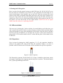
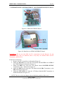
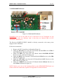
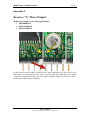
In the receiver tuner module, locate the two pads (indicated by yellow arrows) on
either side of a compartment 'wall'. There is just enough room under the wall to solder
a small wire link between the pads. The signal strength voltage will now be on PIN 9
of the tuner (indicated by red arrow).
ATV LCD KIT
Copyright 2005-2009, MobiComm© Communications