1
Page 12
MobiComm© Communications
2.2.3 Potentiometer
The next step is to place the remaining components on the PCB board; we start with
R4 and R6 the 10K potentiometers. The R4 potentiometer is used to control the
contrast on the LCD display. While the R5 potentiometer can be used to control the
output voltage of the 2A power MOSFET switch. This is handy if you want to control
output power of a PA.
2.2.4 DC Power circuitry
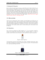
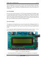
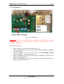
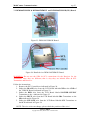
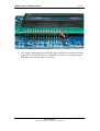
We need to place the voltage regulator U2, market as UA7805, look at Figure 6 to see
how the regulator U2 should be placed.
Figure 6: Position of U2 and T1.
The PCB is ready to have the U2 placed at the top or at the bottom of the PCB, if you
place the LCD display on the top of the PCB you will have to place U2 and T1 at the
bottom. Bend the pins and make sure it can be mounted with the M3 nut and bold
supplied. The power MOSFET T1 needs to be placed on the same side, as the voltage
regulator U2 is careful since this component is static sensitive.
Bend the pins and make sure it can be mounted with the M3 nut and bold supplied.
Don’t forget to place the transistor T2.
The DC Power Jack J5 connector should be place next to capacitor C4; it does not
need an explanation how this should be placed since it can only be placed in one way.
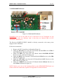
The external connections with the receiver or transmitter boards can be done through
J1 (receiver) and J6 (transmitter). We have supplied connection pins for this but if you
want to connect wires directly on the board its also fine.
ATV LCD KIT
Copyright 2005-2009, MobiComm© Communications