1
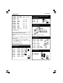
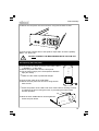
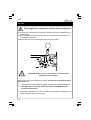
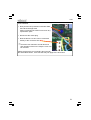
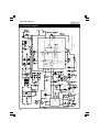
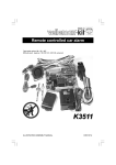
HIGH-END MONO MOSFET
POWER AMPLIFIER
Total solder points: 299
Difficulty level: beginner 1
2
3
4
5 ⌧ advanced
K8040
ILLUSTRATED ASSEMBLY MANUAL
H8040IP-2
Features & specifications
Features :
no compromise high-end design
ideal to place next to the speaker (short wires to the speaker)
auto-power on possibility when input signal is sensed
auto-standby function when no input signal is sensed
exclusive, high finish, solid aluminium enclosure
high quality D-MOS IC output stage
total of 40.000µF power supply capacitors
relay-less speaker DC protection
Real Clipping distortion indication
power output level indication with backlight
bypass output to drive bi-wired speakers using separate amplifiers
double overheating protection with LED indication
high grade speaker and input connections
overload protection
Specifications
input:
• input sensitivity for maximum output:............. 0dBm (= 0.775Vrms)
• input impedance:................................................................ 15Kohm
• minimum auto switch on voltage:....................................... 5mVrms
output:
• maximum RMS output power 4ohm:........................................ 90W
• maximum RMS output power 8ohm:........................................ 70W
• dynamic RMS output power in 4ohm: .................................... 125W
• minimum load impedance: .................................................... 4 ohm
• damping factor (ref. 8ohm 100Hz): ...................................... > 1000
audio:
• signal-to-noise ratio (A-weighted ref. max. out): ................. >105dB
• total harmonic distortion: ............................0.003% @ 1kHz ref 1W
• frequency response:......................... 9Hz to 120kHz (-3dB) in 50W
power requirements:
• AC power: ....... 115Vac (110V to 120V) or 230Vac (220V to 240V)
• consumption:................................................................. 100W max.
dimensions: ..................................290 x 165 x 68mm (11.4" x 6.5" x 2.7")
weight (net):........................................................................ 3.4kg (7.5Lbs)
3
Assembly hints
1. Assembly (Skipping this can lead to troubles ! )
Ok, so we have your attention. These hints will help you to make this project successful. Read them carefully.
1.1 Make sure you have the right tools:
• A good quality soldering iron (25-40W) with a
small tip.
• Wipe it often on a wet sponge or cloth, to keep it clean; then apply
solder to the tip, to give it a wet look. This is called ‘thinning’ and will
protect the tip, and enables you to make good connections.
When solder rolls off the tip, it needs cleaning.
• Thin raisin-core solder. Do not use any flux or grease.
• A diagonal cutter to trim excess wires. To avoid injury when
cutting excess leads, hold the lead so they cannot fly towards the
eyes.
• Needle nose pliers, for bending leads, or to hold components in
place.
• Small blade and Phillips screwdrivers. A basic range is fine.
For some projects, a basic multi-meter is required, or might
be handy
0.0
00
1.2 Assembly Hints :
⇒ Make sure the skill level matches your experience, to avoid disappointments.
⇒ Follow the instructions carefully. Read and understand the entire step before
you perform each operation.
⇒ Perform the assembly in the correct order as stated in this manual
⇒ Position all parts on the PCB (Printed Circuit Board) as shown on the
drawings.
⇒ Values on the circuit diagram are subject to changes.
⇒ Values in this assembly guide are correct*
⇒ Use the check-boxes to mark your progress.
⇒ Please read the included information on safety and customer service
4
Assembly hints
* Typographical inaccuracies excluded. Always look for possible last minute
manual updates, indicated as ‘NOTE’ on a separate leaflet.
1.3 Soldering Hints :
1- Mount the component against the PCB surface
and carefully solder the leads
2- Make sure the solder joints are cone-shaped
and shiny
3- Trim excess leads as close as possible to the
solder joint
AXIAL COMPONENTS ARE TAPED IN
THE CORRECT MOUNTING SEQUENCE !
REMOVE THEM FROM THE TAPE ONE AT
A TIME !
5
Construction
CONSTRUCTION
The unit consists of one main PCB with all the components including transformer
and power supply.
Tip: The pictures on the packaging can be used as a guideline.
However, due to possible modifications they are not 100% reliable.
Mount the components in the order described:
1. Jump wire
4. Resistors (check the color code)
J1
J2
J3
J4
J5
J6
J7
J8
R...
2. Diodes (check the polarity)
D ...
CATHODE
D1: 1N4148
D2: 1N4148
D3: 1N4148
D4: 1N4148
D5: 1N4148
D6: 1N4148
D7: 1N4148
D8: 1N4148
3. Zener diode (check the polarity)
ZD...
CATHODE
ZD1: 20V / 1.3W
(Mount 5mm above the PCB)
6
R1
R2
R3
R4
R5
R6
R7
R8
R9
R10
R11
R12
R13
R14
R15
R16
R17
R18
R19
R20
R21
R22
R23
R24
R25
R26
R27
: 1K
: 1K
: 15K
: 1K
: 470R
: 100R
: 15K
: 15K
: 15K
: 15K
: 470R
: 15K
: 15K
: 100R
: 15K
: 2K2 0.6W
: 100R
: 1K
: 470R
: 2K2 0.6W
: 1M
: 470R
: 1K
: 470K
: 470K
: 470K
: 100K
(1 - 0 - 2)
(1 - 0 - 2)
(1 - 5 - 3)
(1 - 0 - 2)
(4 - 7 - 1)
(1 - 0 - 1)
(1 - 5 - 3)
(1 - 5 - 3)
(1 - 5 - 3)
(1 - 5 - 3)
(4 - 7 - 1)
(1 - 5 - 3)
(1 - 5 - 3)
(1 - 0 - 1)
(1 - 5 - 3)
(2 - 2 - 2 - 9)
(1 - 0 - 1)
(1 - 0 - 2)
(4 - 7 - 1)
(2 - 2 - 2 - 9)
(1 - 0 - 5)
(4 - 7 - 1)
(1 - 0 - 2)
(4 - 7 - 4)
(4 - 7 - 4)
(4 - 7 - 4)
(1 - 0 - 4)
construction
R28 : 2K2 0.6W
R29 : 2K2 0.6W
R30 : 0R
R31 : 15K
R32 : 100K
R33 : 100R
R34 : 0R
R35 : 680R
R36 : 15K
R37 : 100K
R38 : 470R
R39 : 10R / 1W
JGND: 0R
(2 - 2 - 2 - 9)
(2 - 2 - 2 - 9)
(1 - 5 - 3)
(1 - 0 - 4)
(1 - 0 - 1)
IC1 : 8p
IC2 : 8p
IC3 : 6p
(6 - 8 - 1)
(1 - 5 - 3)
(1 - 0 - 4)
(4 - 7 - 1)
(1 - 0 - 0)
7. 10W resistor
R...
If long input signal wires are used a low
input impedance can be useful.
In this case mount for RX a 680R (6-8-1)
resistor.
Check if your pre-amplifier can drive low
impedance!
Our K8021 is OK for low impedance.
Our K8020 is not suited for low
impedance driving.
Rx is normally left open.
5. Capacitors
C1
C2
C3
C4
C5
C6
C7
C8
:
:
:
:
:
:
:
:
100nF
100nF
100nF
100nF
100nF
100nF
100nF
100nF
(104)
(104)
(104)
(104)
(104)
(104)
(104)
(104)
6. IC sockets. Watch the position
of the notch!
c...
5mm
R40 : 4R7 (4.7, 4R7)
8. Capacitors
C9
C10
C11
C12
C13
C14
C15
C16
:
:
:
:
:
:
:
:
2n2 (222)
220n (224)
1uF
1uF
2.2uF
2.2uF
100n / 250V
100n / 250V
(104)
(104)
9. Transistors
T1: BC547
T2: BC547
7
Construction
10. RCA connectors. Mount them
straight and against the PCB
12. Terminal blocks
SK3: 3p "Mains in"
SK4: 3p "Mains transformer"
SK1: MJ-523AG/R
SK2: MJ-523AG/B
Tip:
A red and a black type are delivered
with the kit, if you bought 2 amplifiers
for stereo then one amplifier can be
built with red connectors
(right amp.) and one with the black
connectors.
11. Push button. Mount them
straight against the PCB surface !
SK5+SK6: 2x 2 pole Transformer
output
First slide these two
connectors in each other.
13. Terminal connectors
SW1: TS-04PV
Check that the position
corresponds with the PCB
silk printing.
SK7: 2 pole Temp sensor
SK8: 2 pole Power meter
SW2: KRS1243
8
SK9: LS+
SK10: LS-
construction
14. Coil
16. Voltage regulator. The back
side corresponds to the thick line.
L...
VR1 UA7805
VR...
This coil will have to be made by
yourself. Use the supplied copper
wire (1.5mm) with the kit.
Wind this wire round a 8mm drill or
other round object and make 8 turns.
17. Triac. The back side
corresponds to the thick line.
You can snip off the remaining copper
TR1: TIC246 or eq.
Then remove (scratch) the isolation
from the connections using a knife.
TR...
Mount the coil and make sure to have
a perfect soldering.
L1: 8 Turns dia 8mm
18. Bridge rectifier.
Check the polarity !!
15. Electrolytic capacitors.
Check the polarity !
C17: 10µF
C18: 10µF
C19: 10µF
C20: 10µF
C21: 10µF
C23: 1µF
C24: 10µF
C25: 47µF/63V
C26: 47µF/63V
C27: 47µF/63V
C28: 47µF/63V
C29: 220µF/63V
C30: 220µF/63V
BR1: RS603
C...
19. LEDs
COLOR= 2...5
LD...
CATHODE
LD1: LED3RL (3mm LED)
LD2: LED3RL (3mm LED)
LD3: LED3RL (3mm LED)
9
Construction
20. Power electrolytic capacitors.
Check the polarity !
C31: 10.000µF
C32: 10.000µF
C33: 10.000µF
C34: 10.000µF
21. IC’s. Watch the position of the
notch !
C...
IC1: VK8040 (PIC12C508)
IC2: CA258 or eq.
IC3: MOC3041 / KP3020
22. Mounting front LED’s. Check the polarity !
Short lead = Cathode or - !
CAUTION:
After bending the
leads the long
appearing lead will
be the cathode!
LD ...
C ATH O DE
IMPORTANT
Mount these LED’s exactly like in the
drawing, otherwise some LED’s will
Next: Solder one lead, and check the not fit correctly in the front panel.
Please also use the front panel as a
position, if necessary correct by
positioning reference.
heating the soldering.
First: Bend the leads exactly like the
drawing.
Last: Solder the second connection.
LD4: L-424YDT
LD5: L-424YDT
LD6: L-424YDT
LD7: L-424YDT
12m m
C
7mm
Meter backlight:
LD8 is a white LED serving as backlight
for the power meter.
LD8: L5WD (5mm white)
LD...
CATHODE
3mm
10
18mm
construction
23. Mounting the Power IC
IC4: TDA7293
Mount the support plate onto the IC as shown in the drawing.
Put a drop of silicone compound on both sides of the mica isolator.
Also check the position of the plastic isolator A.
ATTENTION : The bolt should be inserted on the side of the IC holder with the
countersunk opening B !
B
A
A
Drop of heat conductive
compound
DO NOT TIGHTEN THE NUT YET
1.
2.
3.
4.
5.
Position the IC onto the PCB.
Make sure that the support plate is touching the PCB surface.
Tighten the support nut.
Check again that the plate is touching the PCB surface.
Solder the IC connections.
11
Construction
24. Mounting the power transformer and mains voltage selection
Mount the transformer as in the drawing (see also the picture on the packaging)
Use the supplied straps (4 pcs) to fix the transformer.
Primary windings (MAINS) connection:
Check the table on the PCB for the correct voltage selection and connect
the wires :
For 230V (220V to 240V), edge orange, then brown and black.
For 115V (110V to 120V), edge brown, then orange and black.
Using a black marker, erase the not used voltage on the rear panel of the
unit!
230V
120V
ORANGE
BROWN
BROWN
ORANGE
BLACK
BLACK
Secondary windings connection:
Connect the Red, Yellow, Blue and Grey wire to the SK5/SK6 connector, check
the colors on the PCB.
12
Enclosure preparation
25. Enclosure preparation
Cut the thread in the
holes for the enclosure
feet in one of the aluminum profiles, using
the supplied special
M4 screw as a tap.
FIG. 1
Mount the feet on the
aluminum profile, using
two M4 hexagonal Allen
screws. Use the supplied
Allen wrench. It is advisable to stick the protection
adhesive onto the feet.
FIG. 2
Cut the thread in the front
and back of the aluminum
profiles, using the supplied
special M4 screw (4 holes
per piece)
FIG. 3
13
Enclosure preparation
Position the main PCB in the aluminum profile that is prepared with the feet.
Mark the center position of
the three fixation holes on
the aluminum. A reference
indication is also on the
PCB edge.
FIG. 4
Remove the pcb and use a knife or a screwdriver to scratch the paint from
the aluminum fixation, from the hole closest to the back end. This fixation will
be used later to connect the ground and earth.
FIG. 5
Mount the three 5mm (0.14”) spacers as shown in the drawing. Use three
hexagonal screws and 3 washer. Do not tighten the spacers yet.
FIG. 6
5mm M3 spacer
M3 hex. nut
Washer
Position the PCB in the enclosure and check if the position of the spacers is
correct, if so, remove the PCB and tighten the spacers.
14
Enclosure preparation
Using an ohmmeter, measure between the edge of the aluminum profile and
the back spacer, if there is a good electric contact (less then 10 ohm).
If not, repeat the above step to remove the paint under the spacer.
0.0
00
FIG. 7
Slide two M3 nuts and two
hexagonal bolts into the profile,
the nuts will be used for the
temperature sensor, the bolts will
be used for the IC support plate:
FIG. 8
Mount the temperature sensor,
check the exact position. Make sure
there is silicone compound between
the sensor and the enclosure!
Solder the wires of the supplied two
pole connector onto the sensor.
There is no polarity.
11
cm
FIG. 9
15
Final assembly
26. final PCB mount
RE-CHECK CAREFULLY THE PCB FOR MOUNTING AND
SOLDERING ERRORS!
Mount the pcb into the enclosure, check the position of the power IC.
The IC support must fit onto the previously inserted hexagonal bolts.
Make sure there is silicone compound between the IC support and the
enclosure!
Glue the included insert C between the transformer and housing.
C
Make sure the PCB is aligned with the back of the enclosure
IMPORTANT: FIRST fix the IC support
THEN fix the pcb using three 5mm spacers + washer.
DO NOT TIGHTEN THESE FIXATIONS YET.
Note: Not all components are visible on the drawing.
16
Final assembly
27. Speaker and mains connector assembly
Prepare the wiring of the mains connector like in the drawing.
First mount the switch into the mains connector assembly.
Do not forget to isolate the soldering connections using a piece of shrink tube.
Use the supplied 0.5mm wire:
Blue for Neutral
Brown for Live
Yellow/green for earth
Use 3 pieces of about 10cm for later connection to the PCB mains connector.
Brown
Blue
Yellow/green
Mount the speaker connectors onto the rear panel. (black = negative)
Take care of the isolation washers, there are two different types!
See picture.
Make sure the connectors are very tight fit, and do not make electrical
contact with the panel (check using ohm meter!).
Isolation washer !
17
Final assembly
28. Final assembly and connection
Solder a 15cm (2.5mm) wire to the LS connectors. Black = negative, Red=
positive, use a shrink tube to isolate the connection.
Solder a spade terminal to the other end, do not forget the terminal isolation.
15cm
Mount (insert) the mains connector onto the rear panel. Insert a 2A fuse into
the connector (there is also room for a spare fuse).
18
Final assembly
Mount the rear panel onto the enclosure, using two M4 Allen screws.
Connect the speaker wires to the speaker output tabs. Check the polatity!
Black= LS-, Red= LS+.
!
DO NOT CONNECT THE MAINS WIRING WITH THE PCB YET!
29. Preparing the front panel
Connect the two wired connector to the meter, RED =
+, BROWN = - to the meter.
Mount the power meter onto the front panel.
Fix the meter using a piece of transparent adhesive
tape (four sides).
Make sure the meter is positioned straight.
Connect the meter to the PCB (SK8)
Mount the front panel onto the front, using two M4
Allen screws.
Check the position of the LED’s and check if the button is working correctly.
It could be that paint covering the holes, is preventing the buttons from
smooth operation.
Now the three PCB fixations can be tightened.
Check the push button.
19
Test
30. Test
21. Mains voltage connection
!
preparation
Check again all connections
of transformer and mains
Connect the mains wires to the mains connector SK3, Blue= Neutral, green/
yellow= Earth.
Connect a 60W light bulb in series with the Live (Brown wire) and the Live
Connect a 10cm blue wire to the
connection on the PCB.
point
of SK12.
Mount both the fuse and the spare fuse in
theNfuse
holder.
Connect a 10cm brown wire to the
point L of SK12.
Connect a 10cm yellow/green
wire to the earth point of SK12.
Later these connection will be soldered to the mains connector.
!
CAUTION: Some points on the PCB are connected to the
dangerous mains voltage.
Connect the mains AC voltage to the mains. See also the user manual about
the power cord.
Normally after switching ON the amplifier, the light bulb should briefly light up.
If the bulb glows constantly, disconnect the power immediately and
recheck all connections.
• Normally the standby LED on the front panel should light as should both 35V
power indication LED’s LD2 and LD3.
20
Test
Test continued:
• Now push the DC protection test button SW2,
the bulb should light if the
button is pressed. Be careful not to touch any
exposed live parts.
• Disconnect the mains plug.
• Now the brown Live wire can be connected
directly to the connector SK3.
Check the user manual to test all functions
and operation of the unit. Finally the cover can
be mounted.
Please note that the user manual is also used for
the assembled version, some remarks may not apply to the kit version.
21
22
1 Vdd
Vss
GP4/OSC2
8
470K
1M
4
10µ
C24
R21
Auto on
LM258
R27
100K
1N4148
STBY / ON SW1
C21
10µ
R14
100R
R15
15K
Stby / ON
R10
15K
CLIP LED
BC547
T2
R5
470R
LD7
R28
2K2 / 0.6W
LD2
+35V
Power supply indication
R11
470R
LD1
+5V CLIP +5V
47µ/63V
C28
LED3RL
5mV input signal detector for AUTO ON
470K
1K
5
D8
R2
1K
2u2
C14
R35
680R
LED3RL
R23
8
LM258
IC2A
7
R6
100R
ON
L-424YDT
LD5
10µ
STBY
R34
THERMAL
SHUTDOWN
2K2 / 0.6W
R29
100n
C7
LED3RL
LD3
0R
C25
47µ/63V
1
IC2B
+5V
LD8
HFWA05
R8
15K
+5V
+5V
9 STBY
MUTE
BUFFER DRIVER
+35V
STBY-GND
6
Temp error
T1
BC547
10µ
C19
MUTE
SGND
C26
R30
47µ/63V 0R
8
1
R24
470K
L-424YDT
15K
LD6
R4
1K
Temp sens.
2
1
SK7
15K
R12
10
4
3 IN+
C6
C18
10µ
O
100n
C2
IC4
R36 15K
R38
470R
1N4148
D7
Clip detect
TDA7293V
CLIP DET 5
BOOTSTRAP 6
12
OUT 14
BOOT LOADER
R20
DC prot. test2K2 / 0.6W
+35V
10µ
C17
+5V
K8040
INTEGRATED MONO MOSFET AMPLIFIER
1uF
C11
-35V
S/C
PROTECTION
C12
1uF
SW2
I
VR1
UA7805
2K2 / 0.6W
SW KRS1243
R16
-VS
2
3
C5
100n
R3
15K
R7
+5V
C20
R31
15K
2 IN-
100n
-35V
20V 1.3W
15
D2
1N4148
D1
1N4148
CLIP LED
Auto on
Stby / ON
Clip detect
C9
2n2
backlight
+5V
GP5/OSC1/CLKIN 2
3
4
5
15K
R13
100R
220µ/63V
C30
220µ/63V
C29
C31
10.000uF/50V
0R
JGND
+35V
ZD1
-PWVs
R26
GP2/T0CKl
OFF / Stby
2u2
R33
1N4148
1N4148
1N4148
1N4148
10.000uF/50V
C32
C33
C34
+VS
R25
7
GP1 6
GP0
R1
1K
L-424YDT
C13
D6
D5
D4
D3
+
10.000uF/50V
10.000uF/50V
+PWVs
GP3/MCLR/Vpp
PIC12C508A
IC1
C1
100n
4
LD4
6
+5V
2
+5V
IC3
K3020P
C4
-
BRIDGE RS603
AC2
C8
100n
RX
Rload
1
DC Protection (fuse blow)
R19
470R
100n
100n
C3
BR1
7
BYPASS
R18
1K
SK6
SK5
11
SK2
100NF/250VAC
C16
25VAC / 2A
25VAC / 2A
13
R32
100K
INPUT
C15
R17
100R
TR1
SK4
Transfo Prim
AC1
100NF/250VAC
470R
R22
4.7R / 10W
TIC246M
GND
SK1
SK3
R40
Mains in from 2A fuse + switch
2
1
SK8
Power meter
1.0
R9
15K
+5V
47µ/63V
C27
L1
220nF
C10
10R/1W
R39
LS- SK10
LS+ SK9
8T 1.5mm dia 8mm
C23
1µ
100K
R37
Schematic diagram
31. Schematic diagram
L-424YDT
PCB
32. PCB
23
VELLEMAN KIT NV
Legen Heirweg 33
9890 Gavere
Belgium Europe
Info ?: http://www.velleman.be
Modifications and typographical errors reserved
© Velleman Kit nv
H8040IP - 2009 - ED2
5 410329 416775