1
Page 17
MobiComm© Communications
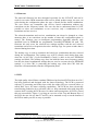
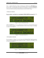
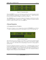
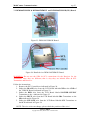
Figure 15: Transmitter Mode.
With the SELECT key you can switch between the Receiver and Transmitter boards
just like during the configuration, you will again see that the “*” market behind the
text line will also change accordingly as can be seen in Figure 15.
The UP/DOWN keys can be used to change the Frequency of the Receiver and/or
Transmitter depending on which line the “*” marker is displayed. Saving the changed
frequency settings can again be done by the MEM key.
4 Normal Operation
4.1 Changing the Receiver Frequency
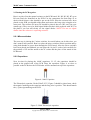
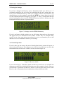
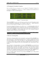
The Receiver frequency can be changed by pressing the UP/DOWN keys while the
“*” marker is displayed on the top line of the display, as can be seen from Figure 16.
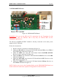
Figure 16: Receiver Mode.
The bar below the receiver frequency is the S-Meter or also known as Signal strength
meter. If you connected the S-Meter input of the board to your Receiver S-Meter
output you can see a bar like this one, depending on the fact if a strong signal is
received or not.
If you have changed the frequency you will see an “!” exclamation marker at the end
of the line indicating that the new settings have not been saved to EEPROM memory.
If you want the next time you power up the board it comes back to this frequency you
should press the MEM key, almost directly you will see the exclamation marker(s)
disappear, and the settings are saved in EEPROM..
ATV LCD KIT
Copyright 2005-2009, MobiComm© Communications