1
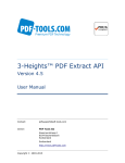
C3 Submersible Fluorometer
Appendix C: Wiring Guide
The C3 Submersible Fluorometer outputs digital data in three formats: 1) Digital data
that can only be read by C3 Submersible Fluorometer’s software, 2) Digital data in
ASCII format that can be read by larger multi parameter systems such as CTD’s, and
3) Digital data that can be read and converted to analog data by the C-Series Analog
Adapter for output to an external datalogger or multimeter.
An 8-pin Impulse cable provides two end connections: 1) a 9-pin RS232 serial port for
connection to a PC or laptop computer and 2) a 12V port for supplying power to the
unit.
C3 Submersible Fluorometer bulkhead and serial port connectors
Sub D Connector
8
2
1
7
5
4
3
2
1
3
4
6
9
5
8
7
6
Wire Guide
Pin Out
Color
C3 Function
Corresponding Sub D Connector Pin
1
Black
V BATT (+)
Power Connector Cable – Center Pin (+)
2
White
V BATT (-)
Power Connector Cable – Housing (-)
3
4
5
6
7
8
Red
Green
Blue
Brown
Yellow
Orange
GND
RX
TX
DTR & DSR
RTS & CTS
N/A
PIN 5
PIN 2
PIN 3
PIN 4, 6
PIN 7, 8
N/A
*Power ground and V Batt (-) are not common.
998-2300
Rev. N
Page 27