1
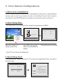
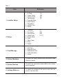
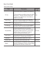
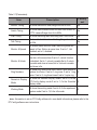
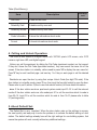
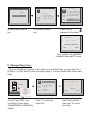
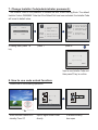
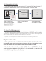
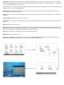
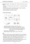
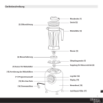
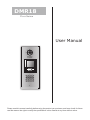
DMR18
Door Station
User Manual
RF CARD
1
2
3
4
5
6
7
8
9
*
0
#
Please read this manual carefully before using the product you purchase, and keep it well for future
use.We reserve the right to modify the specification in this manual at any time without notice.
1.Parts and Functions
Camera Lens
Night View LED
Adjustable Camera
350 mm
Speaker
LCD Screen
ID Card Window
Connectiong Port
RF CARD
3 2 1
Digital Keypad
1
2
3
4
5
6
7
8
9
*
0
#
Microphone
128 mm
With rainy cover
2. Terminal Descriptions
SD Card Slot
L1
L2
+12V
EB+
EBN.O
LK+
LK-
CN-LK
T/R -T/R+
Bus
3 2 1
RF CARD
3 2 1
1
4
•
•
•
•
•
•
•
•
•
•
2
3
5
6
7
8
9
*
0
#
J/KMB
JP-LK
+12V: 12VDC power output.
LK-(GND): power ground.
LK+(COM): common contact of the Relay .
NO.:normally
open contact of the Relay(refer to DT technical guide for Lock connection
detail informations).
EB+: Exit button connection port.
EB-: Exit buton connection port.
JP-LK: For electronic lock safety type setting(refer to Door Station Lock Connections).
T/R-: USB-RS485 communication terminal negative.
T/R+: USB-RS485 communication terninal positive.
Bus(L1,L2): non-polarity bus line.
3.Door Station Mounting
1
2
3
Camera
angle
The view for rainy
cover after mounted
Drill a hole and attach the
rainy cover to it
4
5
Attach screws to fix the
metal box
7
The last view for all mounting
Adjust the camera angle and attach the
metal to the panel and wire correctly.
6
Attach the unit to the rainy
cover correctlly
Attach the baffle to protect
the unit from droping
4. Door Lock Connections
1. Internal Power Supply Mode
Use the power of the system to supply for the electronic lock, so that the lock can be
connected to the door station directly, without an additional power supply for the electronic lock.
Note that the door station can only output 12Vdc power, therefore the kind of lock is limited.
• The rated power of the lock must be less than 12Vdc 300mA when using internal power
supply mode
• The GND must connect to the negative of the lock, and the COM connect to the positive .
• Jumper set to 1-2 position for Power-to-Unlock safety type(Normally open mode); set
to 2-3 position for Power-off-to -Unlock type(Normally closed mode ).Note that the
unlock relay mode is set on the Parameter tab of DT CONFIG software.
• If different unlocking time is needed to be configured, the DT CONFIG software can be
used to change the Unlock Timing on the Parameter tab(see the program section).
A. Connection for Power-to-Unlock type:
+12V
LK - (GND)
LK+(COM)
N.O.
EB+
EB -
+
3
2
1
12V 300mA
set to Normally open on the
Unlock Relay mode on DT-config
software.
Jumper set to 1-2 position
JP_LK
B. Connection for Power--off-to-Unlock type:
+12V
LK - (GND)
LK+(COM)
N.O.
EB+
EB -
-
12V 300mA
Jumper set to 2-3 position
3
2
1
+
JP_LK
set to Normally Closed on the
Unlock Relay mode on DT-config
software.
2. External Power Supply Mode
When the electronic lock is over 12 Vdc, additional power supply for the lock is needed.
• The power supply for the lock must be less than 48Vdc 1.5A.
• The Jumper must be removed when using external power supply. The default setting is
Power-to-Unlock type(Normally open mode), if use Power-off-to-Unlock type, change
the Unlock Relay mode to Normally closed mode .Note that the unlock relay mode is
set on the Parameter tab of DT CONFIG software.
• If different unlocking time is needed to be configured, please use the DT CONFIG
software to change the setting on the Parameter tab(see the program section).
C. Connection for Power-to-Unlock type:
+
+12V
LK - (GND)
LK+(COM)
N.O.
EB+
EB -
+
Remove the Jumper
3
2
1
-
set to Normally Open on the
Unlock Relay mode on DT-config
software.(default)
Note: Cut off this line when
using external power supply
JP_LK
D. Connection for Power--off-to-Unlock type:
-
+
-
Remove the Jumper
+12V
LK - (GND)
LK+(COM)
N.O.
EB+
EB 3
2
1
+
JP_LK
set to Normally Closed on the
Unlock Relay mode on DT-config
software.
Note: Cut off this line when
using external power supply
5. Door Station Configurations
1. About room code(address):
Room Code(also called room address) is a code assigned to each monitor, to identify different
monitors; each monitor have a unique room code in one buidling.The room Code is stored in
each Monitor’s inner EEPROM memory, and does not lose even the monitor is power off.
2. About Debug State:
The Debug State is your starting point for using all the applications on DMR18.
>> Debug State <<
RF CARD
1
4
2
3
5
6
7
8
9
*
0
#
0-#
Redial
1-#
To o l s
2-#
Exits
[9008]
Please Input Password
When Door Station is in
standby, press '#' key
input '9008', then input the
Admin Code.(66666666 by
default)
Debug State menu is launched
Press "2#" key to exit out the debug state.
3. About Debug Tools:
During working at Debug State,press "1#" to enter tools page,Debug Tools overviews is
shown as below:
>> Debug State <<
0-#
Redial
1-#
To o l s
2-#
Exits
Tools
1. Installer Setup
2. Setup
3. Card Memory
Pres NO. 4 . O n l i n e M o n i t o r s
to select 5 . O n l i n e D e v i c e s
*Back
6 . Vo l t a g e M e a s u r e
Table 1:
Item
Submenu
1. Installer Setup
1. ID Code [1]
2. Unlock Timing [05]
3. Unlock Output [0]
4. Card Memory [0]
5. Doorplate Mode
6. Audio Options ...
7. Parameters ...
8. Installer Code ...
9. Default ...
2. Setup
1. Language [1]
2. Tone Select [03]
3. Tone Volume [08]
4. Unlock Code [1111]
5. Display Mode
6. Clock ...
7. Setup Code ...
8. About ...
9. Default ...
3. Card Manage
1. Add Card ...
2. Delete By Card
3. Delete By M.code
4. Cards Information
5. Format
4. Online Monitors
To search the online monitors,input the monitor code
number to search
5. Online Devices
To search the online door stations.Max.4 door station
can be searched
6. Voltage Measure
To check the voltage of the monitor,note that the
monitor must be online.
Basic Tools Detail:
Table 2(Installer Setup):
Item
ID Code
Unlock Timing
Unlock Output
Factory
set
Description
If only one door station is installed in this building, set
to 1;
[1]
If multi door stations are installed, primary door station
Single
must be set to 1, and other slave door stations must
be set from 2 to 4. Note that max. 4 door stations is
available in one building
To set the time that how long the door keeps open
[05]
when door is released. Range from 01 to 99 seconds. 5 seconds
To set the unlock mode to match the corresponding
0
lock.Rand from 0 to 1
Card Manage
To set the card location.If set to 0,the card is saved in
door station.If set to 1, the card is saved in DT-IPC
Doorplate Mode
To set the calling mode.If set to 0,it's the auto
mode,that means the calling will be activated directly
after inputting 2 digits code.If set to 1,it's the manual
mode,that means you should press "#" button to
activate the calling after inputting the code.
Audio Options ...
To set the talking mode.If set to 0,hands free mode is
activated.If set to 1,handset mode is activated.
Parameters ...
To show the parameters,please refer to table 2.1
Installer Code ...
To change door station administrator code
Default ...
Note this operation is irreversible. Once restore is
activated, all parameters will return to factory default
setting except the information of access card.
0
[0]
Auto mode
0
[66666666]
Table 2.1(Parameters):
Item
Description
Factory
set
Monitor Timing
To show the monitor time,Range from 6s to 600s
Switch Timing
To show the surveillance time for each Door Station or
40s
CCTV camera.Range from 6s to 600s
Wait Timing
To show the calling wait time,Rang from 10s to 600s
30s
Talk Timing
To show the limitation time of talking,Range from 10s
to 600s
90s
Monitor & Speack
To enable Indoor Monitor under monitoring state can
speak to Door Station at same time. If set to 1, talk
enabled; set to 0, disabled.
Monitor & Unlock
Ring Numbers
NameList Display
Mode
Working Mode
30s
To enable Monitors under monitoring state can open
the door at the same time.If set to 0, unlock function
is disabled; Set to 1, unlock is enable;Set to 2,unlock [1]
is enable and close at once;Set to 3,unlock is enable
and close in 5s.
To show ring times when door station calls monitor.4
options for choice. If set to 0, ring once. If set to 1,ring [1]
twice. If set to 2, ring three times.If set to 3,cycle ring
To show the namelist display mode.If set to 0,it's the
DT-Config display mode.If set to 1,it's the Simulate [0]
display mode
To show the working mode.If set to 0,it's the apartment
[0]
system mode.If set to 1,it's the villa mode.
Note: this section is set on DT-Config software,for more detail informations,please refer to the
DT-Config software user instructions.
Table 3(Setup):
Item
Language Tone Select Tone Volume Unlock Code Display Mode
Clock ...
Setup Code
Description
To change language.the code format is 4 digits.Please refer
to part 5,section 10(change door station language) for more
detail informations.
Select the chime of Door Station in calling wait state, 12
chord tunes are available, key in 01 to 12 to select.
Adjust the tone volume for dooor station in calling.Rang from
01~15
To change unlock code in Common Code Unlock mode, in
4-digits format. 1111 is the default unlock code.
To select the Door Station screen menu .If set to 0,the
screen displays the visitor's image when talking.If set to 1,the
screen displays icons when talking.
To set date and time.
Date format:if set to 0,date format is DD/MM/YY,if set to
1,date format is MM/DD/YY.
Time format: if set to 0,time format is 24 hour standard.If set
to 1,time format is12 hour standard.
To change the Program Code.
About ...
1. Hardware version---To show the Door Station(including
ACS) hardware information
2. Software version---To show the Door Station(including
ACS) software information
3. Manufacture Date---To show the manufacturing date
4. Dialing Counts---To show the call operation counts
5. Calls Counts---To show the established calling counts
6. Unlock Counts---To show the unlock operation counts
7. Standby Voltage---To show the voltage that the door
station in standby.
8. Working Voltage---To show the voltage that the door
station in working.
9. Video Standard---PAL or NTSC standard
10. UI_CODE---To show the UI byte counts and check box
11. MCM-VER---To show the version and language for MCM
12. Updated---To show the updated time for UI
Default ...
Restore all Setup parameters to factory default setting,Please
note that this operation is an irreversible
Factory
set
01
03
08
[1111]
[0]
[88888888]
Table 4(Card Memory):
Item
Description
Add Card ...
To add the user card
Delete By Card
To delete card by user card
Delete By M.code
To delete card by room code
Cards Information
To show the informations about cards
Format
To format informations about cards
Factory
set
4. Calling and Unlock Operation:
The DMR18 door station is a digital station with 320*240 pixels LCD screen, color CCD
camera, night view LED, and digital keypad.
Visitors can call the apartment by dialing the Flat Code (apartment number) on the keypad.
If they don’t know the Flat Code (apartment number), they can search the name list on the
screen. If the door station is in standby, visitors need to press '9#' to display the user name list. Press"#" key to scroll next/last page. and use key 1 to 8 key on each page to call the desired
flat.
Residents can open the door by using their unique Unlock Code (four-digit PIN code). If the
door station is in standby mode, press '#' key, then input the four-digit unlock to open the door.
Please refer to part 5,section 7(How to use code unlock function) for more detail information.
If the door station works as apartment system mode,input 01~32 to call the relevant
monitor.If the door station works as villa mode,input 01 to call the monitors which its code is
from 00~15. Input 02 to call the monitors which its code is from 16~31.please refer to table
2.1(working mode)
Note:
5. About Default Set:
The Default Set is very important. When the door station miss up the settings in anyway,
the most quickly and easy way to solve the problem is to activate the default setting on door
station. The default settings already have all the right settings for one-building system, that
means the system will work normally without any additional settings. .
1. ID Code.[1]
>> Debug State <<
2. Unlock Timing[05]
0-#
Redial
Tools
1. Installer Setup
2. Setup
1-#
2-#
To o l s
Exits
3. Card Memory
Pres NO. 4 . O n l i n e M o n i t o r s
to select 5 . O n l i n e D e v i c e s
*Back
In Debug State, press '1#'
key
6 . Vo l t a g e M e a s u r e
In Tools menu, press '1'
key
3. Unlock Output[0]
Installer
4. Card Memory [0]
Setup
5. Doorplate Mode
Press No.
to select
*Back
6. Audio Options ...
7. Parameters ...
8. Installer Code...
9. Default
Press '9' key, a
password will be asked.
9. Default...
[--------]
Please Input Password
*Back
# Save
Input Installer code (66666666
by default),then press"#" to save
6. Change Ring Tone:
There are 12 different ringtones, If door station runs as Debug State, you can press [1 #] -->
[2] Setup--> [2]Tone Select to enter tone setting page .If it runs as Normal State, follow these
steps:
[ 8002 ]
Setup
2
3
4
5
6
7
8
9
*
0
#
Please Input Password
Press “#”,Input “8002”, then
input Setup Code or Admin
Code(88888888 or 66666666 by
default)
2 . To n e S e l e c t [ 0 3 ]
[--]
4. Unlock Code[1111]
5. Display Mode
RF CARD
1
1. Language
[1]
2 . To n e S e l e c t [ 0 3 ]
3 . To n e V o l u m e [ 0 3 ]
Press No.
to select
*Back
6. Clock
7. Setup Code
8. About
9. Default
Press “2” to enter tone
select item.
( 01~12)
*Back
# Save
Input 2 digits number,
then press “#” to save
the setting
7. Change Installer Code(administrator password):
The Installer Code is the password to access the door station debug State. The default
Installer Code is '66666666'. Note that if the Default Set have been activated, the Installer Code
will be set to default value.
1. ID Code
>> Debug State <<
[1]
2. Unlock Timing[05]
0-#
Redial
1. Installer Setup
Tools
2. Setup
1-#
2-#
3. Card Memory
To o l s
Exits
Pres NO. 4 . O n l i n e M o n i t o r s
to select 5 . O n l i n e D e v i c e s
6 . Vo l t a g e M e a s u r e
*Back
In Debug State, press '1 #'
key
press '1'
3. Unlock Output[0]
Installer
4. Card Memory [0]
Setup
5. Doorplate Mode
Press1~9 6 . A u d i o O p t i o n s . . .
to select 7 . P a r a m e t e r s . . .
8. Installer Code...
9. Default
*Back
press '8'
8. Installer Code...
[--------]
( * * * * * * * *)
*Back
# Save
Input a new Installer Code and
then press '#' key to confirm
8. How to use code unlock function:
Please refer to the following operations:
[8017 ]
[----]
i Door Open
RF CARD
RF CARD
1
2
3
1
2
3
4
5
6
4
5
6
7
8
9
7
8
9
*
0
#
*
0
#
Please Input Password
When the Door Station is in
standby, Press “#”
Input 4 digits Unlock Code
directly
If verified correctly,
door open
9. Change Unlcok Code:
If door station runs as Debug State, you can press “1#” to activate Tools Menu, then select “2”
to enter setup page,then select 4 item.If it runs as Normal State, follow these steps:
[ 8002 ]
Setup
2
3
4
5
6
7
8
9
*
0
#
Please Input Password
Press “#”,Input “8002”,
then input Setup Code or
Admin Code(88888888 or
66666666 by default)
4. Unlock Code[1111]
[----]
4. Unlock Code[1111]
5. Display Mode
RF CARD
1
1. Language
[1]
2 . To n e S e l e c t [ 0 3 ]
3 . To n e V o l u m e [ 0 3 ]
Press No.
to select
*Back
6. Clock
7. Setup Code
8. About
9. Default
Press “4” to enter unlock
code item.
( * * * *)
*Back
# Save
Input 4 digits number,
then press “#” to update
10. User Card Management:
This section explains how to configure the key fob function on DMR18,The key fob is used to
open the lock. Total 1000 key fobs can be registered with one door station. When swiping the
fob to the door station, the distance must be less than 3 centimeter.
Key Fobs must be registered on the Door station that can be used to open the door.
Register the Key Fobs:
All the registered key fobs are called User Cards/User Key Fobs. New fobs/cards need to
be registered one by one to the Door station to become a valid User Card/User Key Fob; and
every User Card/User Key Fob is related to a certain Monitor Address (Flat code).
When the Doors tation is standby, press [#] --> [9008] -->Password([66666666 by default])
to get into the Debug Mode Menu, then Press [1 #] --> [3] Card Manage -->[1] Add Card to get
into the Add Card page. Please see the followings.
1. AddCard ...
1. AddCard ...
[--]
[01]
Please Input Room Code
# Save
[01]
C a r d numbs : 1 5 9 7 7 1 3 1
Show the card
* Back
Show The Card
# Save
* Back
# Save
Us
C a er
rd
* Back
1. AddCard ...
Enter Add Card menu, and
Room Code is asked.
Input Room Code
Read the card to be
authorized
Delete user cards:
Registered User Cards/Key Fobs can be deleted from the Door station,once doing the delete
operation,the card/key fobs can not open the door anymore. They can also be re-registered
again to become a valid User Card/User Key Fob. There are two ways to delete User Cards/
User Key Fobs:
1. Delete by card: show the unwanted card(s) when the Door station is in Delete Card Mode
2. Delete by room number: delete all the registered User Cards related to that room number.
In Debug State , Press [1 #] -->
[3] Card Manage -->[2] Delete
By Card to enter Delete by Card
page.as shown on the right,
then show the cards you want to
delete one by one.
2. Delete By Card ...
2. Delete By Card ...
C a r d numbs:1 5 9 7 7 1 3 1
Show The Card
Show The Card
* Back
# Save
* Back
# Save
Us
C a er
rd
Delete By Card:
Delete by Room Number:
In Debug State , Press [1 #] -->
[3] Card Manage -->[3] Delete
By M.Code to enter Delete by
M.Code page.as shown on
the right, then Input the Room
Code, press “#” to confirm; all
associated cards will be deleted.
3. Delete By M.code
3. Delete By M.code
[01]
[--]
Please Input Room Code
* Back
# Save
Updat ed
* Back
# Save
Card information:
4. Cards Information
Enter Card Information page, and the
screen will display the authorized User
Cards count, and card read access
events count.
Card Count: 1000
* Back
# Save
Format:
5. Format
Enter Card Format page, a password
will be asked,input 8 digits installer
password (66666666 by default),then
press" #" key to save,format operation
is activated.all card information will be
cleared.
[--------]
Please Input Password
* Back
# Save
11. Change Door Station Language:
It's convenient to change the user interface for DMR18.Just put the config files to the SD card
and by means of the digital keypad of door station,only 30 seconds is needed to update.
Insert SD card
SD Card Slot
L1 L2
J/KMB
+12V
CN-LK
EB+
EBN.O
LK+
LK-
Step 1: Insert the SD card which is
contained config files into the SD card slot
where is at the back of the door station.
Refer to the right diagram.
T/R -T/R+
Bus
3 2 1
JP-LK
3 2 1
Step 2:
If door station runs as Debug State, you can press “1#” to activate Tools Menu, select “2” to
enter setup page,then select 1 item.If it runs as Normal State, follow these steps:
Setup
[ 8002 ]
2
3
4
5
6
7
8
9
*
0
#
1. Language
[----]
4. Unlock Code[1111]
5. Display Mode
RF CARD
1
1. Language
[1]
2 . To n e S e l e c t [ 0 3 ]
3 . To n e V o l u m e [ 0 3 ]
Press No.
to select
*Back
Please Input Password
Press “#”,Input “8002”, then
input Setup Code or Admin
Code
6. Clock
7. Setup Code
8. About
9. Default
( Code Number)
*Back
Input 4 digits code number,
Refer to the table.
Press 1
Language code number:
8101: English
8102: French
8103: Spanish
8104: Italian
8105: German
8106: Dutch
# Save
[8017 ]
i Download
8107: Portuguese
8108: S-Chinese
8109: T-Chinese
8110: Greek
8111: Turkish
8112: Polish
8113: Russian
8114: Slovakia
8115: Hungray
8116: Czech
When the door station output
a long sound DI...,that means
UI updating is finished.
12. Search online door stations and monitors:
“Online Search” is a very useful function that can help the installer to easily check the
connectivity of all the Monitors. Please note, Online does not mean via the internet. Please
refer to the followings:
Check online door stations:
>> Debug State <<
5. Online Devices
0-#
Redial
Tools
1. Installer Setup
[DS1 ] : Online
[DS2 ] : Fail
[DS3 ] : Fail
[DS4 ] : Fail
2. Setup
1-#
To o l s
2-#
Exits
3. Card Memory
Pres NO. 4 . O n l i n e M o n i t o r s
to select 5 . O n l i n e D e v i c e s
*Back
In Debug State, press '1 #'
key
6 . Vo l t a g e M e a s u r e
Press '5' key
* Back
# Save
Check door stations
connection status
Check online monitors:
>> Debug State <<
4. Online Monitors
0-#
Redial
1-#
To o l s
Tools
1. Installer Setup
[--]~[--]
2. Setup
2-#
3. Card Memory
Pres NO. 4 . O n l i n e M o n i t o r s
to select 5 . O n l i n e D e v i c e s
Exits
*Back
In Debug State, press '1 #'
key
6 . Vo l t a g e M e a s u r e
Press '4' key
(Search Range)
* Back
# Save
Input 2 digits
monitor code
4#.Online Monitors
Search Range: input the monitor adress. For example,
input the range from 01 to 05. You will see the connection
status of the selected moinitors.
[ 01 ]
[ 02 ]
[ 03 ]
[ 04 ]
[ 05 ]
* Back
Online
Online
Online
Fall
Online
# Save
13. Namelist function:
DMR18 is designed to have digital keypad and big TFT screen. Its namelist was shown on
the screen and customer can do the calling operation through the digital keypad guided by
Namelist on the screen. 2 types of namelist can be shown on the screen : DT-Config namelist
and Simulate namelist.
Enter namelist page:
Press '9#' in standby mode to display the user namelist. Press"#" key to scroll next/last page.
and use key 1 to 8 key on each page to call the flat you want.Please refer to the DT-Config
softwre user instructions for configure the namelist.
Send namelist to monitors
The namelist can be sent to monitors by door station directly.Connect the door station and
montiors correctly to the system.Then press # 8012 in standby mode ,and input password
(66666666 by default) to send namelist to all the monitors.
6. Specification
●● Power supply: DC24V(Powered by DT-DPS)
●● Camera Lens:
1/4 ACS 4T image sensor with DSP processor
●● Power consumption:
Standby 3W;Working status 9W
●● Screen:
3.5 inch TFT
●● Resolution:
320(R, G, B)X240 pixels
●● Video signal:
CCIR/EIA Optional
●● Wiring:
2 wires, non-polarit
DT-ENG-DMR18-V1 2011S0621
Anleitung für DT27/DT21/25/692 SD/TD7
Videostationen
ManualDT69SD/TDXXSerie-DE/Schick2010
Vorsichtsmassnahmen/Fehler :
Bitte schützen Sie Ihre Anlage vor Erschütterungen
Bitte reinigen Sie alle Komponenten mit einen Bauwolltuch (keine Chemikalien)
Es kann zu Bildverzerrungen kommen wenn andere elektrische Geräte zu nah sind
Bitte schützen Sie alle Geräte vor Feuchtigkeit zu hohen Temperaturen und Staub
Befestigen Sie den Monitor in einer Höhe von ca. 160 cm um eine optimale Sicht auf den Monitor zu gewährleisten.Befestigen
Sie die mitgelieferte Halteplatte mit den Schrauben an der Wand und hängen Sie den Monitor ein.
Anleitung für Innenstation DT27 SD /TD7
Die optimale Montagehöhe für Ihren Monitor beträgt 145-160 cm . Befestigen Sie die Halteplatte an der Wand der Monitor wird
nun von oben eingerastet!
Innenmonitor Teile und Funktionen
Bedienanleitung
Betätigen Sie den Bildschirm oder drücken Sie den Menü Knopf (Sensortaster unten rechts) , der Bildschirm öffnet sich und es
wird der Kalender angezeigt Datum Wochentage und die Uhrzeit .Betätigen Sie den Bildschirm erneut und es erscheint das
Hauptmenü auf den Schirm.
•
Manual Monitor : Zur manuellen Auswahl Ihrer Außenstation es können hier bis zu 4 Türstationen ausgewählt und
einzeln selektiert werden
•
Auto Monitor : Der Es werden alle Verfügbaren Außenstation oder/ und Kameras angezeigt im einstellbaren
Intervallen
•
Intercom : Bei dieser Funktion erreichen Sie das Interkom- Menü
o Interkom by Namlist : Hier werden alle Namen im Haus wenn programmiert (nicht mit Jeder Türstation möglich) angezeigt
sind einzeln anwählbar
o Inner Call : hier können alle Slave - Stationen in einer Wohnung angewählt werden (Je nach Türstation 4 oder
max. 16 Stück)
o Direkt Call Guard Unit: Sie können im System einen Pförtner oder Wachmann anlegen den Sie direkt
anwählen können
•
Memory Playback: Anzeigen der gespeicherten Bilder (immer 4 Stück) Verfügbare Funktionen löschen, vor/zurück ,
alles löschen, ins Hauptmenü
Album : Hier können Photos die auf der SD Karte (nicht im Lieferumfang /-2GB) gespeichert sind angezeigt werden .
Über den Ikon Multimedia >>Album Options kann die Abspieldauer der Albumanzeige eingestellt werden
User Setup : Hier könne Einstellungen wie Lautstärke der Klingel /Nachtklingel Lautstärke / Klingelton Außenstation
Intercom* und Türklingel* Telefonwahlfunktion (siehe Anleitung TPC)
Schließen des Monitors
•
•
•
About : Hier ereichen sie die Experten Einstellung und die Anzeige der Systemdaten (siehe unten )
Klingelton Einstellung :
Im Menü User Setup haben Sie die
Möglichkeit den Klingelton für die
Außenstation für die Interkom Funktion
und für die Türklingel eizustellen .Sie
haben hier 12 unterschiedliche Melodien
zur Verfügung . Dur berühren der
entsprechenden Melodie auf den
Bildschirm wird selbige abgespielt . Dur
betätigen des Exit & Save Ikons wird
die Melodie ausgewählt und
abgespeichert
Bildspeicher Wiedergabe und
Einstellung
•
•
Memory Playback: Anzeigen
der gespeicherten Bilder
(immer 4 Stück) Verfügbare
Funktionen löschen,
vor/zurück , alles löschen, ins
Hauptmenü
Bilder können manual während
des Gesprächs aufgenommen
werden oder ja nach
Einstellung werden 1-4-8
Bilder aller 1,5 Sekunden
aufgenommen Das erste Bild
wird nach Aufbau der
Verbindung nach 3 s erstell
Um die Anzahl der Bilder einzustellen
betätigen sie das Menü Multimedia
dann Memory Options . Geben Sie
hier über das Keypad die anzahl der
Aufnahmen 1-8 an Standart
Einstellung ist 1 Bild
Schlossfunktion betätigen
Sie können währen des Gesprächs den
Unlockknopf (Unlock) oder
Ikon
Auf dem Bildschirm betätigen. Die
Standardmäßige Öffnungsdauer beträgt 5
Sekunden .
Sie können je nach Anlage bis zu 2 Schlösser
anschließen . Es werden Unlock 1 und Unlock 2 als
Icon angezeigt wenn sie den Standart Screen auswählen .
Ferner können in dieser Ansicht Bildeinstellungen vorgenommen
werden
Während des Gesprächs mit dem Besucher
haben sie die Möglichkeit ein Foto durch betätigen
des REC /Capture können Sie manuell ein Bild
während des Gesprächsaufnehmen. Das System
nimmt alles 1,5 Sekunden ein Bild auf Sie können
einstellen 1/4/8 Bilder werden automatisch
aufgenommen und werden auf den Internen
Speicher oder auf einer optionalen SD Karte (max
2GB) gespeichert. Wenn die SD Karte eingelegt
speichert die Anlage automatisch auf SD. Dazu muss
die Aufnahmefunktion an Ihrer Anlage aktiviert werden.
Nun wird bei jeden Klingeln die Aufnahme gestartet.
Experten Einstellung :
Über die Betätigung des Unteren Icon About oder Schick-Handel Logoi werden die Systemdaten Ihres Monitors angezeigt . Berühren Sie den Bildschirm
für 2 Sekunden und sie kommen in das Menü Installations Einstelllungen . Achtung: Ihr Monitor ist für den Masterbetrieb bereits eingerichtet. Es müssen
für eine Standart Verbindung keine Veränderungen im Menü gemacht werden .
Wenn Sie Ihre Anlage mit einer DT592/591 oder 598 Türstation muss diese vor der Einstellung verbunden werden
Code 8000# Standart ist jeder Monitor als Master eingerichtet . Wenn Ihr Monitor mit einer DMR11 Türstation verbunden ist und in einer Wohnung als
Slaver Monitor betrieben werden soll muss je nach anzahl der Monitore Slave 1 2 3 (Set as Slaver Unit) eingeben werden .Bitte beachten es muss immer
einen Master mir dem Code 8000# geben .
8001#-8003# Muss bei den Slavermonitoren an DMR11 und DMR18 eingestellt werden nicht bei DT591 593 598 592 596 , da dort der Slavermonitor
über den DIP Code eingestellt wird . Bei DMR11 und 18 alle Slaver den gelichen DIP Code und Slaver 1-3 über Menü / Bei DT591 ….. über DIP Code
1-14 oder bei DT592 und 598 (2 Fam. 1-14 und 15-32)
In Verbindungen mit den Türstationen DT591/592 und 598 ist diese Einstellung nicht notwendig das die Slave Adressen über den DIP Code des Monitors
(Rückseite ) Codes 1-15 oder 16-28 eingestellt werden
Code 8010 # Set lock Code 0 Bitte diese Einstellung so lassen ! Es liegt Spannung am Schloss an wenn (oder wird potentialfrei geschlossen, je an
Anschluss Mode) beim betätigen des Türöffners
Code 8011# Set lock Code 1 Bei dieser Einstellung liegt immer Spannung an ! Beim betätigen des Türöffners wird selbige unterbrochen ( Standart nicht
verwendet)
Code 8021-8029# Öffnungsdauer des Türöffners 1-9 Sekunden
Code 8004# Wenn Sie den Monitor im Mehrfamilienhaus als Pförtner oder Wächter/Hausmeister festlegen wollen (direkte Anwahl über Guard Unit Call
möglich)
8005# Standarteinstellung nicht als Pförtner
8006# Diese Einstellung bitte verwenden wenn der Monitor als Slaver verwendet wird und beim betätigen der Klingel ein Bild zeigen soll .Wenn diese
Funktion deaktiviert ist wird nur der Klingelton wiedergegeben und erst nach den betätigen des Moniotrs ein Bild gezeigt .Alle anderen Monitore werden
beim annehmen des Gesprächs abgeschaltet und sind wärend des Gesprächs blockiert.
8007# Slaver Monitor kein Bild Standarteinstellung beim Slaverbetrieb Monitor Bild aus
8008-8009 # Einstellung des Datum Formates
Spracheinstellung 8101-8113# : Code für Deutsch sofern noch nicht voreingestellt ist 8105# dafür muss das entsprechende UI File auf SD Karte
gebracht werden und in den Monitor eingelgt werden . Das UI und Mem File gibt es auf Anfrage bei uns.
•
•
•
•
•
•
•
•
•
•
•
•
Stromverbrauch : DC 24V (supplied by Adaptor)
Stromversorgung der Türstation (Türöffner): 12Vdc, 300mA(Internal Power)
Verbrauch im Standby Standby 0.5W,Working status 15W(for kits)
Abmessungf Monitor 7 Inch color TFT-LCD
Display Auflösung : 800*3(RGB)*480 pixels
Video Signal: 1Vp-p,75Ω,CCIR standard
Interner Bildspeicher: 120M
Anzahl der zu speichernden Bilder ca : 800pcs(inner memory),>30000pcs(2G SD card)
Türöffner Zeit einstellbar 1 to 9 seconds, set by Monitor
Arbeits Temperaturbereich: -10ºC ~ 45ºC
Abmessung Monitor 125(H)×225(W)×23(D)mm
Monitor zusätzliche Möglichkeiten
extra Klingelknopf anschließbar
Der Klingeltaster wird an den Monitor für den Etagenruf angeschlossen . Der Monitor klingelt in der für den Etagenruf
eingestellten Melodie der Bildschirm ist aus
extra Klingel
Es kann ein extra Gong mit einer Leistungsaufnahme von 12V 300 mA DC angeschlossen werden . Selbiger klingelt bei
betätigen der Aussenstation und bei betätigen des Etagenrufs so lange bis der Monitor schliesst oder bis das Gespräch
angenommen wird . Wenn Ihr Gong einen höheren verbrauch hat Relais verwenden ( fragen sie Ihren Elektrofachman)
TV Ausgang zum zusätzlichen TV –Anschluss
Es kann ein TV Gerät angeschlossen werden . es wird ein Bild angezeigt wenn ein Bild am Sprechgerät angezeigt wird . Es
wird nur das Bild angezeigt welches gerade am Monitor ausgewählt ist !
Anschlussbeispiel mit DT591 Code 1-16 (siehe Anleitung DT591/2
Gefahrhinweise
Achtung:
Arbeiten am 230V Stromnetz dürfen nur von Fachleuten durchgeführt werden bitte beauftragen Sie einen
Elektrofachmann mit dem Anschluss des Hustschienennetzadapters . Es besteht Lebensgefahr !
Beachten Sie bitte:
Entsorgen sie das Produkt am Ende seiner Lebensdauer, gemäß den geltenden gesetzlichen Vorschriften. Sie können das
Produkt an jeder Kommunalen Sammelstelle für Altgeräte unentgeltlich zur Umwelt und Fachgerechten abgeben .
IX. Hinweis zum Batteriegesetz
Im Zusammenhang mit dem Vertrieb von Batterien oder mit der Lieferungvon Geräten, die Batterien enthalten, ist der
Verkäuferverpflichtet, Sie auf folgendes hinzuweisen:
Sie sind zur Rückgabe gebrauchter Batterien als Endnutzergesetzlich verpflichtet. Sie können Altbatterien, die der Verkäufer als
Neubatterien im Sortiment führt oder geführt hat, unentgeltlich am Versandlager (Versandadresse) des Verkäufers
zurückgeben.
Die auf den Batterien abgebildeten Symbole haben folgende Bedeutung:
= Batterie darf nicht in den Hausmüll gegeben werden
Pb = Batterie enthält mehr als 0,004 Masseprozent Blei
Cd = Batterie enthält mehr als 0,002 Masseprozent Cadmium
Hg = Batterie enthält mehr als 0,0005 Masseprozent Quecksilber.