1
2354235 11/2008
Altivar 71
Variable speed drives
for synchronous and asynchronous motors
Programming manual
Software V3.3
1755855
12/2009
www.schneider-electric.com
This document provided by Barr-Thorp Electric Co., Inc. 800-473-9123
www.barr-thorp.com
Contents
Before you begin______________________________________________________________________________________________ 4
Documentation structure________________________________________________________________________________________ 5
Software enhancements ________________________________________________________________________________________ 6
Steps for setting up____________________________________________________________________________________________ 9
Factory configuration _________________________________________________________________________________________ 10
Application functions__________________________________________________________________________________________ 11
Setup - Preliminary recommendations ____________________________________________________________________________ 15
Graphic display terminal _______________________________________________________________________________________ 18
Description of terminal __________________________________________________________________________________ 18
Description of the graphic screen __________________________________________________________________________ 19
First power-up - [5. LANGUAGE] menu _____________________________________________________________________ 22
Subsequent power ups __________________________________________________________________________________ 23
Programming: Example of accessing a parameter_____________________________________________________________ 24
Quick navigation _______________________________________________________________________________________ 25
Integrated display terminal _____________________________________________________________________________________ 28
Functions of the display and the keys_______________________________________________________________________ 28
Accessing menus ______________________________________________________________________________________ 29
Accessing menu parameters _____________________________________________________________________________ 30
[2. ACCESS LEVEL] (LAC-) ____________________________________________________________________________________ 31
Structure of parameter tables ___________________________________________________________________________________ 34
Interdependence of parameter values ____________________________________________________________________________ 35
Finding a parameter in this document ____________________________________________________________________________ 36
[1.1 SIMPLY START] (SIM-)____________________________________________________________________________________ 37
[1.2 MONITORING] (SUP-) ____________________________________________________________________________________ 45
[1.3 SETTINGS] (SEt-) ________________________________________________________________________________________ 54
[1.4 MOTOR CONTROL] (drC-) _________________________________________________________________________________ 68
[1.5 INPUTS / OUTPUTS CFG] (I-O-) ____________________________________________________________________________ 88
[1.6 COMMAND] (CtL-)_______________________________________________________________________________________ 116
[1.7 APPLICATION FUNCT.] (FUn-) ____________________________________________________________________________ 129
[1.8 FAULT MANAGEMENT] (FLt-) _____________________________________________________________________________ 215
[1.9 COMMUNICATION] (COM-) _______________________________________________________________________________ 239
[1.10 DIAGNOSTICS] ________________________________________________________________________________________ 243
[1.11 IDENTIFICATION] ______________________________________________________________________________________ 245
[1.12 FACTORY SETTINGS] (FCS-) ____________________________________________________________________________ 246
[1.13 USER MENU] (USr-) ____________________________________________________________________________________ 249
[1.14 PROGRAMMABLE CARD] (PLC-) _________________________________________________________________________ 250
[3. OPEN/SAVE AS] _________________________________________________________________________________________ 251
[4. PASSWORD] (COd-)______________________________________________________________________________________ 253
[6 MONITORING CONFIG.] ___________________________________________________________________________________ 255
[7 DISPLAY CONFIG.] _______________________________________________________________________________________ 259
[MULTIPOINT SCREEN] _____________________________________________________________________________________ 264
Maintenance _______________________________________________________________________________________________ 265
Faults - Causes - Remedies ___________________________________________________________________________________ 266
User settings tables _________________________________________________________________________________________ 272
Index of functions ___________________________________________________________________________________________ 274
Index of parameter codes _____________________________________________________________________________________ 275
1755855 12/2009
3
This document provided by Barr-Thorp Electric Co., Inc. 800-473-9123
www.barr-thorp.com
Before you begin
Read and understand these instructions before performing any procedure on this drive.
DANGER
HAZARDOUS VOLTAGE
• Read and understand the Installation Manual before installing or operating the ATV71 drive. Installation, adjustment,
repair, and maintenance must be performed by qualified personnel.
• The user is responsible for compliance with all international and national electrical standards in force concerning
protective grounding of all equipment.
• Many parts of this variable speed drive, including the printed circuit boards, operate at the line voltage. DO NOT
TOUCH.
Use only electrically insulated tools.
• DO NOT touch unshielded components or terminal strip screw connections with voltage present.
• DO NOT short across terminals PA/+ and PC/- or across the DC bus capacitors.
• Install and close all the covers before applying power or starting and stopping the drive.
• Before servicing the variable speed drive
- Disconnect all power.
- Place a “DO NOT TURN ON” label on the variable speed drive disconnect.
- Lock the disconnect in the open position.
• Disconnect all power including external control power that may be present before servicing the drive. WAIT 15
MINUTES to allow the DC bus capacitors to discharge. Then follow the DC bus voltage measurement procedure
given in the Installation Manual to verify that the DC voltage is less than 42 V. The drive LEDs are not accurate
indicators of the absence of DC bus voltage.
Failure to follow these instructions will result in death or serious injury.
CAUTION
DAMAGED EQUIPMENT
Do not operate or install any drive that appears damaged.
Failure to follow this instruction can result in equipment damage.
4
1755855 12/2009
This document provided by Barr-Thorp Electric Co., Inc. 800-473-9123
www.barr-thorp.com
Documentation structure
The following Altivar 71 technical documents are available on the Telemecanique website (www.telemecanique.com) as well as on the
CD-ROM supplied with the drive.
Installation Manual
This bulletin contains complete mounting and wiring instructions.
Programming manual
This describes the functions, parameters and use of the drive terminal (integrated display terminal and graphic display terminal).
The communication functions are not described in this manual, but in the manual for the bus or network used.
Communication Parameters Manual
This manual describes:
• The drive parameters with specific information for use via a bus or communication network.
• The operating modes specific to communication (state chart).
• The interaction between communication and local control.
Manuals for Modbus, CANopen, Ethernet, Profibus, INTERBUS, Uni-Telway, FIPIO
and Modbus Plus, etc.
These manuals describe the assembly, connection to the bus or network, signaling, diagnostics, and configuration of the communicationspecific parameters via the integrated display terminal or the graphic display terminal.
They also describe the communication services of the protocols.
ATV 58-58F/ATV 71 Migration Manual
This manual describes the differences between the Altivar 71 and the Altivar 58/58F and explains how to replace an Altivar 58 or 58F,
including how to replace drives communicating on a bus or a network.
ATV 78/ATV 61/71 Migration Manual
This manual describes the differences between the Altivar 61/71 and Altivar 78 and explains how to replace an Altivar 78.
1755855 12/2009
5
This document provided by Barr-Thorp Electric Co., Inc. 800-473-9123
www.barr-thorp.com
Software enhancements
Since the Altivar ATV 71 was first launched, it has benefited from the addition of several new functions. The software version has been
updated to V3.3. The old versions can be replaced by this new one without any modifications.
Although this documentation relates to version V3.3, it can still be used with earlier versions, as the updates merely involve the addition of
values and parameters, and none of the parameters of the previous versions have been modified or removed.
Enhancements made to version V1.2 in comparison to V1.1
Factory setting
Note 1: In version V1.1, the analog input was 0 ± 10 V. For safety reasons, in the new version this input has been set to 0 + 10 V.
Note 2: In version V1.1, analog output AO1 was assigned to the motor frequency. In the new version, this output is not assigned
at all.
With the exception of these two parameters, the factory settings of version V1.1 remain the same in the new version. The new functions
are factory-set to disabled.
Motor frequency range
The maximum output frequency has been extended from 1000 to 1600 Hz (depending on the drive rating and control profile).
New parameters and functions
Menu [1.2 MONITORING] (SUP-)
Addition of internal states and values relating to the new functions described below.
Menu [1.3 SETTINGS] (SEt-)
•
•
•
•
[High torque thd.] (ttH) page 66.
[Low torque thd.] (ttL) page 66.
[Pulse warning thd.] (FqL) page 67.
[Freewheel stop Thd.] (FFt) page67.
Menu[1.4 MOTOR CONTROL] (drC-)
• [rpm increment] (InSP) page 69.
• Extension of the following configurations to all drive ratings; previously limited to 45 kW (60 HP) for ATV71pppM3X and to 75 kW
(100 HP) for ATV71pppN4:synchronous motor[Sync. mot.] (SYn) page 71, sinus filter [Sinus filter] (OFI) page 82, noise reduction
[Noise reduction] (nrd) page 83, braking balance [Braking balance] (bbA) page 85.
Menu [1.5 INPUTS / OUTPUTS CFG] (I-O-)
• Input Al1 can now be configured to 0 +10 V or 0 ± 10 V via [AI1 Type] (AI1t) page 94.
• [AI net. channel] (AIC1) page 98.
• New methods of assigning relays and logic outputs page 103 : rope slack, high torque threshold, low torque threshold, motor in
forward rotation, motor in reverse rotation, measured speed threshold reached, load variation detection.
• Analog output AO1 can now be used as a logic output and assigned to relay functions and logic outputs, page 108.
• New method of modifying the scale of analog outputs page 110 using the parameters [Scaling AOx min] (ASLx) and [Scaling AOx
max] (ASHx).
• New methods of assigning logic outputs page 111: signed motor torque and measured motor speed.
• New methods of assigning alarm groups page 115 : rope slack, high torque threshold, low torque threshold, measured speed
threshold reached, load variation detection.
6
1755855 12/2009
This document provided by Barr-Thorp Electric Co., Inc. 800-473-9123
www.barr-thorp.com
Software enhancements
Menu [1.7 APPLICATION FUNCT.] (Fun-)
• The summing, subtraction and multiplication reference functions can now be assigned to virtual input [Network AI] (AIU1) page 136.
• New parameter [Freewheel stop Thd.] (FFt) page 141 used to set a threshold for switching to freewheel at the end of a stop on ramp
or fast stop.
• Brake engage at regulated zero speed [Brake engage at 0] (bECd) page 162.
• Weight [Weight sensor ass.] (PES) page 167 can now be assigned to virtual input [Network AI] (AIU1).
• New "rope slack" function page 171, with the parameters [Rope slack config.] (rSd) and [Rope slack trq level] (rStL).
• Use of the ramp [Acceleration 2] (AC2) page 179 when starting and "waking up" the PID function.
• The torque limitation [TORQUE LIMITATION] (tOL-) page 186 can now be configured in whole % or in 0.1% increments using [Torque
increment] (IntP) and assigned to virtual input [Network AI] (AIU1).
• New "stop at distance calculated after deceleration limit switch" function page 195, with the parameters [Stop distance] (Std), [Rated
linear speed] (nLS) and [Stop corrector] (SFd).
• Positioning by sensors or limit switch [POSITIONING BY SENSORS] (LPO-) page 196 can now be configured in positive logic or
negative logic using [Stop limit config. (SAL) and [Slowdown limit cfg.] (dAL).
• Parameter set switching [PARAM. SET SWITCHING] (MLP-) page 199 can now be assigned to the frequency thresholds attained
[Freq. Th. att.] (FtA) and [Freq. Th. 2 attain.] (F2A).
• New half-floor: menu [HALF FLOOR] (HFF-) page 213.
Menu [1.8 FAULT MANAGEMENT] (FLt)
• Possibility of reinitializing the drive without turning it off, via [Product reset] (rP) page 220.
• Possibility of reinitializing the drive via a logic input without turning it off, using [Product reset assig.] (rPA) page 220.
• The possibility of configuring the "output phase loss" fault [Output Phase Loss] (OPL) page 224 to [Output cut] (OAC) has been
extended to all drive ratings (previously limited to45 kW (60 HP) for ATV71pppM3X and 75 kW (100HP) for ATV71pppN4).
• The external fault [EXTERNAL FAULT] (EtF-) page 227 can now be configured in positive or negative logic via [External fault config.]
(LEt).
• New monitoring function based on speed measurement via "Pulse input" page 234, via the [FREQUENCY METER] menu (FqF-).
• New function for detecting load variation page 236, via the [DYNAMIC LOAD DETECT] menu (dLd-).
• Short-circuit faults on the braking unit can now be configured via[Brake res. fault Mgt] bUb) page 238.
Menu [7 DISPLAY CONFIG.]
• In [7.4 KEYPAD PARAMETERS] page 261, the [KEYPAD CONTRAST] and [KEYPAD STAND-BY] parameters to adjust the contrast
and stand-by mode of the graphic display unit.
Enhancements made to version V1.6 in comparison to V1.2
Extension of the range with the addition of ATV71ppppY drives for 500 to 690 V supplies.
There are no new parameters, but the adjustment ranges and factory settings of some parameters have been adapted to the new voltages.
Menu [1.5 INPUTS / OUTPUTS CFG] (I-O-)
Increased adjustment range for the relay and logic output delay parameters: 0 to 60000 ms instead of 0 to 9999 ms.
Enhancements made to version V2.5 in comparison to V1.6
Menu [1.3 SETTINGS] (SEt-)
• New parameters [Skip Frequency] (JPF), [Skip Frequency 2] (JF2) and [3rd Skip Frequency] (JF3) page 67 allow to avoid critical
speed which generate resonances.
• New parameter [Skip.Freq.Hysteresis] (JFH) page 67 to adjust the range of skip frequency.
• Possibility to adjust the parameter [Torque ratio] (trt) page 67 (visible too in [TORQUE CONTROL] (tOr-) menu page 183).
Important:
For V2.5 version, the behaviour of the following functions is different from the previous version when type of stop "freewheel" is selected
(factory value):
• [LIMIT SWITCHES] (LSt-) function,
• [POSITIONING BY SENSORS] (LPO-) function,
• "shutdown" command by communication (see CiA402 state chart in communication parameters manual).
Actually, on previous versions, type of stop "freewheel" was not well done.
1755855 12/2009
7
This document provided by Barr-Thorp Electric Co., Inc. 800-473-9123
www.barr-thorp.com
Software enhancements
Enhancements made to version V2.7 in comparison to V2.5
Menu [7 DISPLAY CONFIG.]
• Addition in [7.4 KEYPAD PARAMETERS] page 261 of [Power up menu]. This parameter allows to choose the menu which displays
on the drive on power up.
Menu [1.3 SETTINGS] (SEt-)
The adjustment range of [Time to restart] (ttr) page 163 can now be configured between 0.00 and 15.00 seconds.
Enhancements made to version V3.3 in comparison to V2.7
[1.7 APPLICATION FUNCT.] (Fun-) menu
New parameters and functions
• New parameter [REGEN CONNECTION] (AFE) page 215 . With this parameter it is possible to retun the braking energy to the mains
and reduce the harmonics
8
1755855 12/2009
This document provided by Barr-Thorp Electric Co., Inc. 800-473-9123
www.barr-thorp.com
Steps for setting up
INSTALLATION
v 1 Consult the Installation Manual
PROGRAMMING
Procedure applicable if the factory configuration, page 10, and use of the
[SIMPLY START] (SIM-) menu only are sufficient for the application.
b 2 Power up without run command
v If you are using a separate power
supply for the control section, follow
the instructions on page 15.
b 3 Select the language, if the drive
has a graphic display terminal
b 4 Configure the [SIMPLY START]
Tips:
• Before you start programming, complete
the user setting tables, page 274.
• Perform an auto-tuning operation to
optimize performance, page 43.
• If you get lost, return to the factory
settings, page 250.
Note: Check that the wiring of the
drive is compatible with its
configuration.
(SIM-) menu
v 2-wire or 3-wire control
v Macro configuration
v Motor parameters
) Perform an auto-tuning
operation
v Motor thermal current
v Acceleration and deceleration
ramps
v Speed variation range
b 5 Start
1755855 12/2009
9
This document provided by Barr-Thorp Electric Co., Inc. 800-473-9123
www.barr-thorp.com
Factory configuration
Drive factory settings
The Altivar 71 is factory-set for the most common operating conditions:
• Macro configuration: Start/Stop
• Motor frequency: 50 Hz
• Constant torque application with asynchronous motor and sensorless flux vector control
• Normal stop mode on deceleration ramp
• Stop mode in the event of a fault: freewheel
• Linear, acceleration and deceleration ramps: 3 seconds
• Low speed: 0 Hz
• High speed: 50 Hz
• Motor thermal current = rated drive current
• Standstill injection braking current = 0.7 x rated drive current, for 0.5 seconds
• No automatic starts after a fault
• Switching frequency 2.5 kHz or 4 kHz depending on drive rating
• Logic inputs:
- LI1: forward, LI2: Forward (2 operating direction), 2-wire control on transition
- L13, L14, LI5, LI6: inactive (not assigned)
• Analog inputs:
- AI1: speed reference 0 +10 V
- AI2: 0-20 mA, inactive (not assigned)
• Relay R1: The contact opens in the event of a fault (or drive off).
• Relay R2: Inactive (not assigned)
• Analog output AO1: 0-20 mA, inactive (not assigned)
If the above values are compatible with the application, the drive can be used without changing the settings.
Option card factory settings
The option card inputs/outputs are not factory-set.
10
1755855 12/2009
This document provided by Barr-Thorp Electric Co., Inc. 800-473-9123
www.barr-thorp.com
Application functions
The tables on the following pages show the most common combinations of functions and applications, in order to guide your selection.
The applications in these tables relate to the following machines in particular:
• Hoisting: cranes, overhead cranes, gantries (vertical hoisting, translation, slewing), lifting platforms
• Elevators: elevators in retrofit up to 1.2 m/s
• Handling: palletizers/depalletizers, conveyors, roller tables
• Packing: carton packers, labeling machines
• Textiles: weaving looms, carding frames, washing machines, spinners, drawing frames
• Wood: automatic lathes, saws, milling
• High inertia: centrifuges, mixers, unbalanced machines (beam pumps, presses)
• Process
Each machine has its own special features, and the combinations listed here are neither mandatory nor exhaustive.
Some functions are designed specifically for a particular application. In this case, the application is identified by a tab in the
margin on the relevant programming pages.
Motor control functions
High inertia
b
b
b
b
b
b
b
b
b
b
V/f ratio
71
Sensorless flux vector control
71
b
b
b
b
Flux vector control with sensor
71
b
b
b
b
2-point vector control
71
b
Open-loop synchronous motor
71
b
Output frequency of up to 1600 Hz
69
b
b
Motor overvoltage limiting
83
b
b
-
b
DC bus connection (see User's Manual)
Motor fluxing using a logic input
154
Switching frequency of up to 16 kHz
82
Auto-tuning
70
b
b
b
b
b
b
b
b
b
Process
Wood
b
Textiles
Packing
Handling
Page
Lifts
Functions
Hoisting
Applications
b
b
b
b
b
1755855 12/2009
b
b
11
This document provided by Barr-Thorp Electric Co., Inc. 800-473-9123
www.barr-thorp.com
Application functions
Functions on speed references
b
Reference delinearization (magnifying glass effect)
93
b
b
Frequency control input
125
Reference switching
126 - 135
b
Reference summing
134
b
Reference subtraction
134
b
Reference multiplication
134
b
S ramps
137
Jog operation
145
Preset speeds
146
+ speed / - speed using single action pushbuttons
(1 step)
149
+ speed / - speed using double action pushbuttons
(2 steps)
149
+/- speed around a reference
151
Save reference
153
b
b
b
b
b
b
b
b
b
b
Process
b
High inertia
b
Wood
Packing
91
Textiles
Handling
Differential bipolar reference
Functions
Lifts
Page
Hoisting
Applications
b
b
b
b
b
b
b
b
12
1755855 12/2009
This document provided by Barr-Thorp Electric Co., Inc. 800-473-9123
www.barr-thorp.com
Application functions
Application-specific functions
141
Limit switch management
155
b
b
b
Brake control
157
b
b
b
Load measurement
166
b
b
High-speed hoisting
168
b
Rope slack
171
b
PID regulator
173
Torque monitoring
182
b
b
Motor/generator torque limit
185
b
b
Load sharing
85
b
b
Line contactor control
189
b
b
Output contactor control
191
Positioning by limit switches or sensors
193
b
b
Stop at distance calculated after deceleration limit switch
195
b
b
ENA system (mechanical with unbalanced load)
80
Parameter switching
198
b
Motor or configuration switching
201
b
Traverse control
205
Stop configuration
141
Evacuation
212
b
Half floor
213
b
b
b
Process
High inertia
Fast stop
Wood
Textiles
Packing
Handling
Page
Lifts
Functions
Hoisting
Applications
b
b
b
b
b
b
b
b
b
b
b
b
b
b
b
b
b
b
b
b
b
1755855 12/2009
13
This document provided by Barr-Thorp Electric Co., Inc. 800-473-9123
www.barr-thorp.com
Application functions
Safety functions/fault management
Textiles
Wood
High inertia
Process
-
Packing
Power Removal (safety function, see User's Manual)
Handling
Page
Lifts
Functions
Hoisting
Applications
b
b
b
b
b
b
b
b
b
Deferred stop on thermal alarm
226
Alarm handling
115
b
b
b
b
b
b
b
b
218 to 240
b
b
b
b
b
b
b
b
IGBT tests
229
b
b
b
b
b
b
b
b
Catch a spinning load
222
b
b
b
Braking resistor thermal protection
238
b
b
b
b
Motor protection with PTC probes
218
b
b
b
b
b
b
b
Undervoltage management
228
b
b
b
4-20mA loss
230
b
b
Uncontrolled output cut (output phase loss)
224
b
Automatic restart
221
b
Use of the "Pulse input" input to measure the speed of
rotation of the motor.
234
b
Load variation detection
236
b
Fault management
b
b
b
b
b
b
b
14
1755855 12/2009
This document provided by Barr-Thorp Electric Co., Inc. 800-473-9123
www.barr-thorp.com
Setup - Preliminary recommendations
Turning on and configuring the drive
DANGER
UNINTENDED EQUIPMENT OPERATION
• Before turning on and configuring the Altivar 71, check that the PWR (POWER REMOVAL) input is deactivated (at
state 0) in order to prevent unintended operation.
• Before turning on the drive, or when exiting the configuration menus, check that the inputs assigned to the run
command are deactivated (at state 0) since they can cause the motor to start immediately.
Failure to follow these instructions will result in death or serious injury.
CAUTION
INCOMPATIBLE LINE VOLTAGE
Before turning on and configuring the drive, ensure that the line voltage is compatible with the supply voltage range shown
on the drive nameplate. The drive may be damaged if the line voltage is not compatible.
Failure to follow this instruction can result in equipment damage.
Separate control section power supply
Only supply power to the power section the next time the drive is powered up when:
A) The drive control section is powered independently of the power section (P24 and 0V terminals).
B) Whenever an option card is added or replaced.
Power switching via line contactor
CAUTION
RISK OF EQUIPMENT DAMAGE
• Avoid operating the contactor frequently (premature ageing of the filter capacitors).
• Cycle times < 60 s may result in damage to the pre-charge resistor.
Failure to follow these instructions can result in equipment damage.
User adjustment and extension of functions
• The display unit and buttons can be used to modify the settings and to extend the functions described in the following pages.
• Return to factory settings is made easy by the [1.12 FACTORY SETTINGS] (FCS-) menu, see page 248.
• There are three types of parameter:
- Display: Values displayed by the drive
- Adjustment: Can be changed during operation or when stopped
- Configuration: Can only be modified when stopped and no braking is taking place. Can be displayed during operation.
DANGER
UNINTENDED EQUIPMENT OPERATION
• Check that changes made to the settings during operation do not present any danger.
• We recommend stopping the drive before making any changes.
Failure to follow these instructions will result in death or serious injury.
1755855 12/2009
15
This document provided by Barr-Thorp Electric Co., Inc. 800-473-9123
www.barr-thorp.com
Setup - Preliminary recommendations
Starting
Important:
• In factory settings mode, the motor can only be supplied with power once the “forward”, “reverse” and “DC injection stop” commands
have been reset:
- On power-up or a manual fault reset or after a stop command
If they have not been reset, the drive will display "nSt" but will not start.
• If the automatic restart function has been configured ([Automatic restart] (Atr) parameter in the [1.8-FAULT MANAGEMENT] (FLt-)
menu, see page 221), these commands are taken into account without a reset being necessary.
Test on a low power motor or without a motor
• In factory settings mode, [Output Phase Loss] detection (OPL) page 224 is active (OPL = YES). To check the drive in a test or
maintenance environment without having to switch to a motor with the same rating as the drive (particularly useful in the case of high
power drives), deactivate [Output Phase Loss] (OPL = no).
• Configure [Motor control type] (Ctt) = [V/F 2pts] (UF2) or [V/F 5pts] (UF5) ([1.4-MOTOR CONTROL] (drC-) menu, see page 71)
CAUTION
UNINTENDED EQUIPMENT OPERATION
Motor thermal protection will not be provided by the drive if the motor current is less than 0.2 times the rated drive current.
Provide an alternative means of thermal protection.
Failure to follow this instruction can result in equipment damage.
Using motors in parallel
• Configure [Motor control type] (Ctt) = [V/F 2pts] (UF2) or [V/F 5pts] (UF5) ([1.4-MOTOR CONTROL] (drC-) menu, see page 71)
CAUTION
UNINTENDED EQUIPMENT OPERATION
Motor thermal protection is no longer provided by the drive. Provide an alternative means of thermal protection on every
motor.
Failure to follow this instruction can result in equipment damage.
16
1755855 12/2009
This document provided by Barr-Thorp Electric Co., Inc. 800-473-9123
www.barr-thorp.com
Setup - Preliminary recommendations
ATV71pppY - Network which presents often under voltage
To assure an optimal running of an ATV71pppY used on network which presents often under voltage (network voltage contained between
425 V and 446 V), it is necessary to adjust [Prevention level] (UPL) = 383 V ([1.8-FAULT MANAGEMENT] (FLt-) menu, see page 229).
Using motor with nominal voltage lower than drive supply voltage
• Configure [Vector Control 2pt] (UC2) = [Yes] (YES) ([1.4-MOTOR CONTROL] (drC-) menu, see page 73)
CAUTION
UNINTENDED EQUIPMENT OPERATION
• To protect a motor which has a nominal voltage lower than drive supply voltage, it is mandatory to use
[Vector Control 2pt] (UC2) function in order to limit maximal voltage of the motor lower than network voltage.
• Nevertheless, it is necessary to check that instantaneous voltage applied to the motor (link to DC bus voltage) are
compatible with characteristics of this one.
Failure to follow these instructions can result in equipment damage.
1755855 12/2009
17
This document provided by Barr-Thorp Electric Co., Inc. 800-473-9123
www.barr-thorp.com
Graphic display terminal
Although the graphic display terminal is optional for low-power drives, it is a standard component on high-power drives (see catalog). The
graphic display terminal can be disconnected and connected remotely (on the door of an enclosure for example) using the cables and
accessories available as options (see catalog).
Description of terminal
1 Graphic display
2 Function keys
F1, F2, F3, F4,
see page 19.
7 ESC key: Aborts a value, a
parameter or a menu to return
to the previous selection
3 STOP/RESET
button
6 Button for reversing the direction
of rotation of the motor
4 RUN button
5 Navigation button:
• Press (ENT):
- To save the current value
- To enter the selected menu or parameter
• Turn CW/
CCW:
- To increment or decrement a value
- To go to the next or previous line
- To increase or decrease the reference if control via
the terminal is activated
Note: Buttons 3, 4, 5 and 6 can be used to control the drive directly, if control via the terminal is activated.
Disconnected terminal
When the terminal is disconnected, 2 LEDs become visible:
Green LED:
DC bus ON
Red LED:
Fault
HMI Modbus
18
1755855 12/2009
This document provided by Barr-Thorp Electric Co., Inc. 800-473-9123
www.barr-thorp.com
Graphic display terminal
Description of the graphic screen
1
RDY
2
Term
+0.00 Hz
0A
6
1 DRIVE MENU
1.1 SIMPLY START
1.2 MONITORING
3
1.3 SETTINGS
1.4 MOTOR CONTROL
1.5 INPUTS / OUTPUTS CFG
4
Code
F1
<<
>>
Quick
F2
F3
F4
5
1. Display line. Its content can be configured; the factory settings show:
• The drive state (see page 20)
• The active control channel:
- Term: Terminals
- HMI: Graphic display terminal
- MDB: Integrated Modbus
- CAN: Integrated CANopen
- NET: Communication card
- APP: Controller Inside card
• Frequency reference
• Current in the motor
2. Menu line. Indicates the name of the current menu or submenu.
3. Menus, submenus, parameters, values, bar charts, etc., are displayed in drop-down window format on a maximum of 5 lines.
The line or value selected by the navigation button is displayed in reverse video.
4. Section displaying the functions assigned to the F1 to F4 keys and aligned with them, for example:
• Code F1
: Displays the code of the selected parameter, i.e., the code corresponding to the 7-segment display.
• HELP F1
: Contextual help
• <<
F2
: Navigate horizontally to the left, or go to previous menu/submenu or, for a value, go to the next digit up, displayed
in reverse video (see the example on page 21).
• >>
F3
: Navigate horizontally to the right or go to next menu/submenu (going to the [2 ACCESS LEVEL] menu in this
example) or, for a value, go to the next digit down, displayed in reverse video (see the example on page 21).
• Quick F4
: Quick navigation, see page 25.
The function keys are dynamic and contextual.
Other functions (application functions) can be assigned to these keys via the [1.6 COMMAND] menu.
If a preset speed is assigned to a function key and if the function key is pressed, the motor will run at this preset speed until another preset
speed or JOG is pressed, speed reference is changed, or Stop key is pressed.
5.
Indicates that there are no more levels below this display window.
Indicates that there are more levels below this display window.
6.
Indicates that this display window does not scroll further up.
Indicates that there are more levels above this display window.
1755855 12/2009
19
This document provided by Barr-Thorp Electric Co., Inc. 800-473-9123
www.barr-thorp.com
Graphic display terminal
Drive state codes:
-
ACC: Acceleration
CLI: Current limit
CTL: Controlled stop on input phase loss
DCB: DC injection braking in progress
DEC: Deceleration
FLU: Motor fluxing in progress
FST: Fast stop
NLP: No line power (no line supply on L1, L2, L3)
NST: Freewheel stop
OBR: Auto-adapted deceleration
PRA: Power Removal function active (drive locked)
RDY: Drive ready
RUN: Drive running
SOC: Controlled output cut in progress
TUN: Auto-tuning in progress
USA: Undervoltage alarm
20
1755855 12/2009
This document provided by Barr-Thorp Electric Co., Inc. 800-473-9123
www.barr-thorp.com
Graphic display terminal
Example configuration windows:
RDY
Term +0.00Hz
5 LANGUAGE
0A
When only one selection is possible, the selection made is indicated by
Example: Only one language can be chosen.
English
Français
Deutsch
Español
Italiano
<<
>>
Quick
Chinese
Turkish
Russian
PARAMETER SELECTION
1.3 SETTINGS
Ramp increment
Acceleration
Deceleration
Acceleration 2
Deceleration 2
Edit
When multiple selection is possible, the selections made are indicated by
Example: A number of parameters can be chosen to form the [USER MENU].
Example configuration window for one value:
RDY
Term
Acceleration
+0.00Hz
0A
RDY
Term
Acceleration
+0.00Hz
0A
>>
9.51 s
Min = 0.01
<<
>>
951 s
Max = 99.99
Quick
Min = 0.01
<<
>>
Max = 99.99
Quick
The << and >> arrows (keys F2 and F3) are used to select the digit to be modified, and the navigation button is rotated to increase or
decrease this number.
1755855 12/2009
21
This document provided by Barr-Thorp Electric Co., Inc. 800-473-9123
www.barr-thorp.com
Graphic display terminal
First power-up - [5. LANGUAGE] menu
The first time the drive is powered up, the user will automatically be guided through the menus as far as [1. DRIVE MENU].
The parameters in the [1.1 SIMPLY START] submenu must be configured and auto-tuning performed before the motor is started up.
Display for 3 seconds following power-up
ATV31HU22N4
2.2kW/3HP 380/480V
Config. n°1
3 seconds
5 LANGUAGE
English
Français
Deutsch
Español
Italiano
Automatically switches to [5 LANGUAGE]
menu 3 seconds later.
Select the language and press ENT.
Chinese
Russian
Turkish
RDY
Term +0.00Hz
2 ACCESS LEVEL
0.0A
Switches to [2 ACCESS LEVEL] menu
(see page 31)
Select the access level and press ENT.
Basic
Standard
Advanced
Expert
RDY
Term +0.00Hz
0.0A
1 DRIVE MENU
1.1 SIMPLY START
1.2. MONITORING
1.3. SETTINGS
1.4. MOTOR CONTROL
1.5. INPUTS / OUTPUTS CFG
Code
<<
>>
Quick
Switches to [1 DRIVE MENU]
(see page 27)
ESC
RDY
Term +0.00Hz
MAIN MENU
1 DRIVE MENU
2 ACCESS LEVEL
3 OPEN / SAVE AS
4 PASSWORD
5 LANGUAGE
Code
0.0A
Press ESC to return to [MAIN MENU]
Quick
22
1755855 12/2009
This document provided by Barr-Thorp Electric Co., Inc. 800-473-9123
www.barr-thorp.com
Graphic display terminal
Subsequent power ups
ATV71HU22N4
2.2kW/3HP 380/480V
Config. n°1
3 seconds later, switches to
[1. DRIVE MENU] or to
[1.14 PROGRAMMABLE CARD].
or, if the Controller Inside card is present
3 seconds
RDY
Term
+38Hz
0A
1. DRIVE MENU
1.1 SIMPLY START
1.2 MONITORING
1.3 SETTINGS
1.4 MOTOR CONTROL
1.5 INPUTS / OUTPUTS CFG
Code
<<
>>
Quick
RDY
Term +0.00Hz
0A
1.14 PROGRAMMABLE CARD
Modbus add Prg C.
:17
DATE/TIME SETTINGS
<<
>>
Quick
10 seconds
RDY
If no operator inputs are made,
switches to "Display" automatically
10 seconds later (the display will
vary depending on the selected
configuration).
Term
+38Hz
Frequency ref.
0A
38 Hz
Min=0
RDY
ENT
Max=60
Quick
Term +0.00Hz
1.3 SETTINGS
Ramp increment:
Acceleration
Deceleration:
Acceleration 2:
Deceleration 2:
Code
<<
>>
0A
01
9.51 s
9.67 s
12.58 s
13.45 s
Quick
Menu selected in
[Power up menu]
page 265
ESC
RDY
Users can return to [MAIN MENU]
by pressing ENT or ESC.
Term
+38Hz
MAIN MENU
1 DRIVE MENU
2 ACCESS LEVEL
3 OPEN / SAVE AS
4 PASSWORD
5 LANGUAGE
Code
0A
Quick
1755855 12/2009
23
This document provided by Barr-Thorp Electric Co., Inc. 800-473-9123
www.barr-thorp.com
Graphic display terminal
Programming: Example of accessing a parameter
Accessing the acceleration ramp
RDY
Term +0.00Hz
0A
1 DRIVE MENU
1.1 SIMPLY START
1.2 MONITORING
1.3 SETTINGS
1.4 MOTOR CONTROL
1.5 INPUTS / OUTPUTS CFG
Code
<<
>>
Quick
RDY
ENT
ESC
Term +0.00Hz
1.3 SETTINGS
Ramp increment:
Acceleration
Deceleration:
Acceleration 2:
Deceleration 2:
Code
<<
>>
0A
01
9.51 s
9.67 s
12.58 s
13.45 s
Quick
RDY
Term +0.00Hz
Acceleration
0A
ENT
9.51 s
ENT or
Min = 0.01
ESC
<<
>>
Max = 99.99
Quick
Note:
• To select a parameter:
- Turn the navigation button to scroll vertically.
• To modify a parameter:
- Use the << and >> keys (F2 and F3) to scroll horizontally and select the digit to be modified (the selected digit changes to white
on a black background).
- Turn the navigation button to modify the digit.
• To cancel the modification:
- Press ESC.
• To save the modification:
- Press the navigation button (ENT).
24
1755855 12/2009
This document provided by Barr-Thorp Electric Co., Inc. 800-473-9123
www.barr-thorp.com
Graphic display terminal
Quick navigation
If the "Quick" function is displayed above the F4 key, you can gain quick access to a parameter from any screen.
Example:
RDY
Term +0.00Hz
0A
1.4 MOTOR CONTROL
Standard mot. freq:
5 0Hz IEC
Rated motor power: 0.37 kW (0.5 HP)
Rated motor volt.:
206 V
Rated mot. current:
1.0 A
Rated motor freq.:
50.0 Hz
Code
<<
>>
Quick
Press F4 to access the Quick screen, which contains
4 selection options.
• [HOME]: Return to [MAIN MENU].
RDY
RDY
Term +0.00Hz
0A
QUICK NAVIGATION
RETURN TO MAIN MENU
DIRECT ACCESS TO...
10 LAST MODIFICATIONS
GOTO MULTIPOINT SCREEN
ENT
Code
See page 266
Term +0.00Hz
MAIN MENU
1 DRIVE MENU
2 ACCESS LEVEL
3 OPEN / SAVE AS
4 PASSWORD
5 LANGUAGE
Code
0A
Quick
• [DIRECT ACCESS TO...] : Opens the direct access window, which
will contain the text "1". The function keys << and >> (F2 and F3)
can be used to select each of the numbers and the navigation
button to increment or decrement the numbers: 1.3 in the example
below.
RDY
Term +0.00Hz
0A
DIRECT ACCESS TO...
RDY
ENT
1.3
SETTINGS
<<
>>
Term +0.00Hz
1.3 SETTINGS
Ramp increment:
Acceleration
Deceleration:
Acceleration 2:
Deceleration 2:
Code
<<
>>
0A
01
9.51 s
9.67 s
12.58 s
13.45 s
Quick
• [10 LAST MODIFICATIONS]: Opens a window in which the last 10
parameters modified can be accessed directly.
RDY
Term +0.00Hz
0A
10 LAST MODIFICATIONS
Acceleration:
10 s
ENA prop.gain:
1.2
Rated mot. current:
15 A
Preset speed 4:
20 Hz
Preset speed 5:
30 Hz
Code
RDY
Term +0.00Hz
Rated mot. current
ENT
0A
15.0 A
ESC
1755855 12/2009
<<
>>
25
This document provided by Barr-Thorp Electric Co., Inc. 800-473-9123
www.barr-thorp.com
Graphic display terminal
[MAIN MENU] - Menu mapping
RDY
Term +0.00Hz
MAIN MENU
1 DRIVE MENU
2 ACCESS LEVEL
3 OPEN / SAVE AS
4 PASSWORD
5 LANGUAGE
Code
6 MONITORING CONFIG.
7 DISPLAY CONFIG.
0A
RDY
Term +0.00Hz
0A
1 DRIVE MENU
1.1 SIMPLY START
1.2 MONITORING
1.3 SETTINGS
1.4 MOTOR CONTROL
1.5 INPUTS / OUTPUTS CFG
Code
<<
>>
Quick
1.6 COMMAND
1.7 APPLICATION FUNCT.
1.8 FAULT MANAGEMENT
1.9 COMMUNICATION
1.10 DIAGNOSTICS
1.11 IDENTIFICATION
1.12 FACTORY SETTINGS
1.13 USER MENU
1.14 PROGRAMMABLE CARD
Quick
Content of [MAIN MENU] menus
[1 DRIVE MENU]
See next page
[2 ACCESS LEVEL]
Defines which menus can be accessed (level of complexity)
[3 OPEN / SAVE AS]
Can be used to save and recover drive configuration files
[4 PASSWORD]
Provides password protection for the configuration
[5 LANGUAGE]
Language selection
[6 MONITORING CONFIG.]
Customization of information displayed on the graphic display terminal during operation
[7 DISPLAY CONFIG.]
• Customization of parameters
• Creation of a customized user menu
• Customization of the visibility and protection mechanisms for menus and parameters
26
1755855 12/2009
This document provided by Barr-Thorp Electric Co., Inc. 800-473-9123
www.barr-thorp.com
Graphic display terminal
[1 DRIVE MENU]
RDY
Term +0.00Hz
0A
1 DRIVE MENU
1.1 SIMPLY START
1.2 MONITORING
1.3 SETTINGS
1.4 MOTOR CONTROL
1.5 INPUTS / OUTPUTS CFG
Code
<<
>>
Quick
1.6 COMMAND
1.7 APPLICATION FUNCT.
1.8 FAULT MANAGEMENT
1.9 COMMUNICATION
1.10 DIAGNOSTICS
1.11 IDENTIFICATION
1.12 FACTORY SETTINGS
1.13 USER MENU
1.14 PROGRAMMABLE CARD
Content of [1. DRIVE MENU] menus:
[1.1 SIMPLY START]:
Simplified menu for a quick start
[1.2 MONITORING]:
Visualization of current, motor and input/output values
[1.3 SETTINGS]:
Accesses the adjustment parameters, which can be modified during operation
[1.4 MOTOR CONTROL]:
Motor parameters (motor nameplate, auto-tuning, switching frequency, control algorithms, etc.)
[1.5 INPUTS / OUTPUTS CFG]:
I/O configuration (scaling, filtering, 2-wire control, 3-wire control, etc.)
[1.6 COMMAND]:
Configuration of command and reference channels (graphic display terminal, terminals, bus, etc.)
[1.7 APPLICATION FUNCT.] :
Configuration of application functions (e.g., preset speeds, PID, brake logic control, etc.)
[1.8 FAULT MANAGEMENT]:
Configuration of fault management
[1.9 COMMUNICATION]:
Communication parameters (fieldbus)
[1.10 DIAGNOSTICS]:
Motor/drive diagnostics
[1.11 IDENTIFICATION]:
Identifies the drive and the internal options
[1.12 FACTORY SETTINGS]:
Access to configuration files and return to factory settings
[1.13 USER MENU]:
Specific menu set up by the user in the [7. DISPLAY CONFIG.] menu
[1.14 PROGRAMMABLE CARD]: :
Configuration of optional Controller Inside card
1755855 12/2009
27
This document provided by Barr-Thorp Electric Co., Inc. 800-473-9123
www.barr-thorp.com
Integrated display terminal
Low-power Altivar 71 drives (see catalog) feature an integrated display terminal with a 7-segment 4-digit display. The graphic display
terminal described on the previous pages can also be connected to these drives as an option.
Functions of the display and the keys
• 2 Modbus status LEDs
• Four 7-segment
displays
• 2 CANopen status LEDs
• Returns to the previous
menu or parameter, or
increases the
displayed value
• Exits a menu or parameter,
or aborts the displayed
value to return to the
previous value in the
memory
• Goes to the next menu
or parameter, or
decreases the
displayed value
Note:
• Pressing
or
• Enters a menu or
parameter, or saves the
displayed parameter or
value
does not store the selection.
• Press and hold down (>2 s)
or
to scroll through the data quickly.
Save and store the selection: ENT
The display flashes when a value is stored.
Normal display, with no fault present and no startup:
-
43.0 : Display of the parameter selected in the SUP menu (default selection: motor frequency)
CLI: Current limit
CtL: Controlled stop on input phase loss
dCb: DC injection braking in progress
FLU: Motor fluxing in progress
FSt: Fast stop.
nLP: No line power (no line supply on L1, L2, L3)
nSt: Freewheel stop
Obr: Auto-adapted deceleration
PrA: Power Removal function active (drive locked)
rdY = Drive ready
SOC: Controlled output cut in progress
tUn: Auto-tuning in progress
USA: Undervoltage alarm
The display flashes to indicate the presence of a fault.
28
1755855 12/2009
This document provided by Barr-Thorp Electric Co., Inc. 800-473-9123
www.barr-thorp.com
Integrated display terminal
Accessing menus
Power-up
XXX
Displays the state of the drive
ENT
ENT
ESC
SIMPLY START
SIM-
(page 37) Simplified menu for fast startup
ESC
ENT
ESC
SUP-
MONITORING
(page 45) Visualization of current, motor and input/output values
ESC
ENT
SETTINGS
(page 54) Adjustment parameters, can be modified during
operation
MOTOR CONTROL
(page 70) Motor parameters (motor nameplate, auto-tuning,
switching frequency, control algorithms, etc.)
INPUTS / OUTPUTS CFG
(page 88) I/O configuration (scaling, filtering, 2-wire control,
3-wire control, etc.)
ESC
SEtESC
ENT
ESC
drCESC
ENT
ESC
I-OESC
ENT
ESC
CtL-
Menus
ESC
COMMAND
(page 116) Configuration of command and reference channels
(graphic display terminal, terminals, bus, etc.)
ENT
ESC
FUn-
APPLICATION FUNCT.
(page 129)Configuration of application functions (e.g., preset
speeds, PID, brake logic control, etc.)
FAULT MANAGEMENT
(page 217) Configuration of fault management
ESC
ENT
ESC
FLtESC
ENT
ESC
CON-
COMMUNICATION
(page 241) Communication parameters (fieldbus)
ESC
ENT
FACTORY SETTINGS
(page 248) Access to configuration files and return to factory
settings
USER MENU
(page 251) Specific menu, set up by the user using the graphic
display terminal.
ESC
FCSESC
ENT
ESC
USrESC
ENT
ESC
SPL-
PROGRAMMABLE CARD
(page 252) Menu for the Controller Inside card, if present.
ESC
ENT
ESC
COd-
PASSWORD
(page 255)
ESC
ENT
ESC
LAC-
ACCESS LEVEL
(page 31)
ESC
A dash appears after menu and submenu codes to differentiate them from parameter codes.
Examples: FUn- menu, ACC parameter.
The grayed-out menus may not be accessible depending on the control access (LAC) configuration.
1755855 12/2009
29
This document provided by Barr-Thorp Electric Co., Inc. 800-473-9123
www.barr-thorp.com
Integrated display terminal
Accessing menu parameters
Save and store the displayed selection :
SEt-
ENT
ACC
ESC
The display flashes when a value is stored.
Value or assignment
Parameter
Menu
ENT
ENT
15 0
.
ESC
ESC
dEC
26 0
1 flash
(save)
26 0
.
.
ENT
(Next parameter)
ENT
Menu
1st
All the menus are "drop-down" type menus, which means that after the last parameter, if
you continue to press
, you will return to the first parameter and, conversely, you can
switch from the first parameter to the last parameter by pressing
.
ESC
nth
last
Selection of multiple assignments for one parameter
Example: List of group 1 alarms in [INPUTS / OUTPUTS CFG]
menu (I-O-)
A number of alarms can be selected by "checking" them as
follows.
ENT
I-OESC
Alarm not selected
The digit on the right indicates:
Alarm selected
selected
not selected.
The same principle is used for all multiple selections.
30
1755855 12/2009
This document provided by Barr-Thorp Electric Co., Inc. 800-473-9123
www.barr-thorp.com
[2. ACCESS LEVEL] (LAC-)
With graphic display terminal
Basic
Access to 5 menus only, and access to 6 submenus only in the
[1. DRIVE MENU] menu.
A single function can be assigned to each input.
RDY
Term +0.00Hz
2 ACCESS LEVEL
0A
Basic
Standard
Advanced
Expert
<<
>>
Quick
RDY
Term +0.00Hz
MAIN MENU
1 DRIVE MENU
2 ACCESS LEVEL
3 OPEN / SAVE AS
4 PASSWORD
5 LANGUAGE
Code
<<
>>
0A
RDY
Term +0.00Hz
1. DRIVE MENU
1.1 SIMPLY START
1.2. MONITORING
1.3. SETTINGS
1.11. IDENTIFICATION
1.12. FACTORY SETTINGS
Code
<<
>>
1.13 USER MENU
Quick
0A
Quick
Standard
This is the factory-set level. Access to 6 menus only, and access to all
submenus in the [1. DRIVE MENU] menu.
A single function can be assigned to each input.
RDY
Term +0.00Hz
MAIN MENU
1 DRIVE MENU
2 ACCESS LEVEL
3 OPEN / SAVE AS
4 PASSWORD
5 LANGUAGE
Code
6 MONITORING CONFIG.
0A
RDY
Quick
Advanced
Access to all menus and submenus.
Several functions can be assigned to
each input.
RDY
Term +0.00Hz
MAIN MENU
1 DRIVE MENU
2 ACCESS LEVEL
3 OPEN / SAVE AS
4 PASSWORD
5 LANGUAGE
Code
6 MONITORING CONFIG.
7 DISPLAY CONFIG.
0A
Term +0.00Hz
0A
1 DRIVE MENU
1.1 SIMPLY START
1.2 MONITORING
1.3 SETTINGS
1.4 MOTOR CONTROL
1.5 INPUTS / OUTPUTS CFG
Code
<<
>>
Quick
1.6 COMMAND
1.7 APPLICATION FUNCT.
1.8 FAULT MANAGEMENT
1.9 COMMUNICATION
1.10 DIAGNOSTICS
1.11 IDENTIFICATION
1.12 FACTORY SETTINGS
1.13 USER MENU
1.14 PROGRAMMABLE CARD
Quick
Expert
Access to all menus and submenus as for [Advanced] level, and access to
additional parameters.
Several functions can be assigned to each input.
RDY
Term +0.00Hz
MAIN MENU
1 DRIVE MENU
2 ACCESS LEVEL
3 OPEN / SAVE AS
4 PASSWORD
5 LANGUAGE
Code
6 MONITORING CONFIG.
7 DISPLAY CONFIG.
0A
Quick
1755855 12/2009
31
This document provided by Barr-Thorp Electric Co., Inc. 800-473-9123
www.barr-thorp.com
[2. ACCESS LEVEL] (LAC-)
With integrated display terminal:
Power-up
XXX
Displays the state of the drive
ENT
ESC
SIM-
ESC
COdENT
ESC
LAC-
Code
ACCESS LEVEL
ESC
Name/Description
Factory setting
LACbAS
Std
Adu
Epr
Std
• bAS: Limited access to SIM, SUP, SEt, FCS, USr, COd and LAC menus. Only one function can be assigned to
each input.
• Std: Access to all menus on the integrated display terminal. Only one function can be assigned to each input.
• AdU: Access to all menus on the integrated display terminal. Several functions can be assigned to each input.
• EPr: Access to all menus on the integrated display terminal and access to additional parameters. Several functions
can be assigned to each input.
32
1755855 12/2009
This document provided by Barr-Thorp Electric Co., Inc. 800-473-9123
www.barr-thorp.com
[2. ACCESS LEVEL] (LAC-)
Comparison of the menus that can be accessed on the graphic display terminal/
integrated display terminal
[3 OPEN/SAVE AS]
-
[4 PASSWORD]
COd- (Password)
[5 LANGUAGE]
-
[1 DRIVE MENU]
[1.1 SIMPLY START]
SIM- (Simply start)
[1.2 MONITORING]
SUP- (Monitoring)
[1.3 SETTINGS]
SEt- (Settings)
[1.11 IDENTIFICATION]
-
[1.12 FACTORY SETTINGS]
FCS- (Factory settings)
[1.13 USER MENU]
USr- (User menu)
A single function can be assigned to each input.
A single function can be assigned to
each input.
[1.4 MOTOR CONTROL]
drC- (Motor control)
[1.5 INPUTS / OUTPUTS CFG]
I-O- (I/O configuration)
[1.6 COMMAND]
CtL- (Command)
[1.7 APPLICATION FUNCT.]
FUn- (Application functions)
[1.8 FAULT MANAGEMENT]
FLt- (Fault management)
[1.9 COMMUNICATION]
COM- (Communication)
[1.10 DIAGNOSTICS]
-
Expert EPr
LAC- (Access level)
Advanced AdU
[2 ACCESS LEVEL]
Access level
Standard Std (factory setting)
Integrated display terminal
Basic bAS
Graphic display terminal
[1.14 PROGRAMMABLE CARD] (1) PLC- (Controller Inside card) (1)
[6 MONITORING CONFIG.]
-
A single function can be assigned to each input.
A single function can be assigned to
each input.
[7 DISPLAY CONFIG.]
-
Several functions can be assigned to each input.
Several functions can be assigned
to each input.
Expert parameters
Expert parameters
Several functions can be assigned to each input.
Several functions can be assigned
to each input.
(1) Can be accessed if the Controller Inside card is present.
1755855 12/2009
33
This document provided by Barr-Thorp Electric Co., Inc. 800-473-9123
www.barr-thorp.com
Structure of parameter tables
The parameter tables in the descriptions of the various menus can be used with both the graphic display terminal and the integrated display
terminal. They, therefore, contain information for these two terminals in accordance with the description below.
Example:
5
[1.7 APPLICATION FUNCT.] (FUn-)
1
Code
2
6
Name/Description
b
UPd-
Adjustment range Factory setting
[+/- SPEED]
Function can be accessed for reference channel [Ref.2 channel] (Fr2) = [+/- speed] (UPdt) ,
see page 126
3
4
USP
no
LI1
M [+ speed assignment]
v [No] (nO): function inactive
v [LI1] (LI1)
[No] (nO)
7
8
1. Name of menu on 4-digit 7-segment display.
5. Name of menu on graphic display terminal.
2. Submenu code on 4-digit 7-segment display.
6. Name of submenu on graphic display terminal.
3. Parameter code on 4-digit 7-segment display.
7. Name of parameter on graphic display terminal.
4. Parameter value on 4-digit 7-segment display.
8. Value of parameter on graphic display terminal.
Note :
• The text in square brackets [ ] indicates what you will see on the graphic display terminal.
• The factory settings correspond to [Macro configuration] (CFG) = [Start/Stop] (StS). This is the macro configuration set at
the factory.
34
1755855 12/2009
This document provided by Barr-Thorp Electric Co., Inc. 800-473-9123
www.barr-thorp.com
Interdependence of parameter values
The configuration of certain parameters modifies the adjustment range of other parameters, in order to reduce the risk of errors. This may
result in the modification of a factory setting or a value you have already selected.
Example:
1. [Current Limitation] (CLI) page 61 set to 1.6 In or left at its factory setting, 1.5 In
2. [Switching freq.] (SFr) page 61 set to 1 kHz (and confirmed with "ENT") restricts [Current Limitation] (CLI) to 1.36 In
3. If [Switching freq.] (SFr) is increased to 4 kHz, [Current limitation] (CLI) is no longer restricted, but remains at 1.36 In. If you require
1.6 In, you must reset [Current Limitation] (CLI).
1755855 12/2009
35
This document provided by Barr-Thorp Electric Co., Inc. 800-473-9123
www.barr-thorp.com
Finding a parameter in this document
The following assistance with finding explanations on a parameter is provided:
• With the integrated display terminal: Direct use of the parameter code index, page 277, to find the page giving details of the
displayed parameter.
• With the graphic display terminal: Select the required parameter and press F1 : [Code]. The parameter code is displayed instead
of its name while the key is held down.
Example: ACC
RDY
Term +0.00Hz
1.3 SETTINGS
Ramp increment:
Acceleration
Deceleration:
Acceleration 2:
Deceleration 2:
Code
<<
>>
0A
01
9.51 s
9.67 s
12.58 s
13.45 s
Quick
RDY
Code
Term +0.00Hz
1.3 SETTINGS
Ramp increment:
ACC
Deceleration:
Acceleration 2:
Deceleration 2:
Code
<<
>>
0A
01
9.51 s
9.67 s
12.58 s
13.45 s
Quick
Then use the parameter code index, page 277, to find the page giving details of the displayed parameter.
36
1755855 12/2009
This document provided by Barr-Thorp Electric Co., Inc. 800-473-9123
www.barr-thorp.com
[1.1 SIMPLY START] (SIM-)
With graphic display terminal:
RDY
Term +0.00Hz
MAIN MENU
1 DRIVE MENU
2 ACCESS LEVEL
3 OPEN / SAVE AS
4 PASSWORD
5 LANGUAGE
Code
0A
RDY
ENT
Quick
Term +0.00Hz
0A
1 DRIVE MENU
1.1 SIMPLY START
1.2 MONITORING
1.3 SETTINGS
1.4 MOTOR CONTROL
1.5 INPUTS / OUTPUTS CFG
Code
<<
>>
Quick
RUN
ENT
Term
+50.00Hz 80A
1.1 SIMPLY START
2/3 wire control
Macro configuration
Customized macro
Standard mot. freq
Input phase loss
Code
<<
>>
Quick
With integrated display terminal:
Power-up
XXX
Displays the state of the drive
ENT
ENT
ESC
SIMPLY START
SIMESC
ESC
SUP-
ESC
LAC-
The [1.1-SIMPLY START] (SIM-) menu can be used for fast startup, which is sufficient for the majority of applications.
The parameters in this menu can only be modified when the drive is stopped and no run command is present, with the following exceptions:
• Auto-tuning, which causes the motor to start up
• The adjustment parameters on page 44
Note : The parameters of the [1.1 SIMPLY START] (SIM-) menu must be entered in the order in which they appear, as the later
ones are dependent on the first ones.
For example [2/3 wire control] (tCC) must be configured before any other parameters.
The [1.1 SIMPLY START] (SIM-) menu should be configured on its own or before the other drive configuration menus. If a modification
has previously been made to any of them, in particular in [1.4 MOTOR CONTROL] (drC-), some [1.1 SIMPLY START] (SIM-) parameters
may be changed, for example, the motor parameters, if a synchronous motor has been selected. Returning to the [1.1 SIMPLY START]
(SIM-) menu after modifying another drive configuration menu is unnecessary but does not pose any risk. Changes following modification
of another configuration menu are not described, to avoid unnecessary complication in this section.
Macro configuration
Macro configuration provides a means of speeding up the configuration of functions for a specific field of application.
7 macro configurations are available:
•
•
•
•
•
•
•
Start/stop (factory configuration)
Handling
General use
Hoisting
PID regulator
Communication bus
Master/slave
Selecting a macro configuration assigns the parameters in this macro configuration.
Each macro configuration can still be modified in the other menus.
1755855 12/2009
37
This document provided by Barr-Thorp Electric Co., Inc. 800-473-9123
www.barr-thorp.com
[1.1 SIMPLY START] (SIM-)
Macro configuration parameters
Assignment of the inputs/outputs
Input/
output
[Start/Stop] [M. handling] [Gen. Use]
[Hoisting]
[PID regul.] [Network C.] [Mast./
slave]
AI1
[Ref.1 channel] [Ref.1 channel]
[Ref.1 channel]
[Ref.1 channel]
[Ref.1 channel] [Ref.2 channel] [Ref.1 channel]
(PID reference) ([Ref.1 channel]
= integrated
Modbus) (1)
AI2
[No]
[Summing ref. 2]
[Summing ref. 2]
[No]
[PID feedback] [No]
[Torque
reference]
AO1
[No]
[No]
[No]
[No]
[No]
[No]
[No]
R1
[No drive flt]
[No drive flt]
[No drive flt]
[No drive flt]
[No drive flt]
[No drive flt]
[No drive flt]
R2
[No]
[No]
[No]
[Brk control]
[No]
[No]
[No]
LI1 (2-wire) [Forward]
[Forward]
[Forward]
[Forward]
[Forward]
[Forward]
[Forward]
LI2 (2-wire) [Reverse]
[Reverse]
[Reverse]
[Reverse]
[Reverse]
[Reverse]
[Reverse]
LI3 (2-wire) [No]
[2 preset speeds] [Jog]
[Fault reset]
[PID integral
reset]
[Ref. 2
switching]
[Trq/spd
switching]
LI4 (2-wire) [No]
[4 preset speeds] [Fault reset]
[External fault]
[2 preset PID
ref.]
[Fault reset]
[Fault reset]
LI5 (2-wire) [No]
[8 preset speeds] [Torque limitation]
[No]
[4 preset PID
ref.]
[No]
[No]
LI6 (2-wire) [No]
[Fault reset]
[No]
[No]
[No]
[No]
[No]
LI1 (3-wire) Stop
Stop
Stop
Stop
Stop
Stop
Stop
LI2 (3-wire) [Forward]
[Forward]
[Forward]
[Forward]
[Forward]
[Forward]
[Forward]
LI3 (3-wire) [Reverse]
[Reverse]
[Reverse]
[Reverse]
[Reverse]
[Reverse]
[Reverse]
LI4 (3-wire) [No]
[2 preset speeds] [Jog]
[Fault reset]
[PID integral
reset]
[Ref. 2
switching]
[Trq/spd
switching]
LI5 (3-wire) [No]
[4 preset speeds] [Fault reset]
[External fault]
[2 preset PID
ref.]
[Fault reset]
[Fault reset]
LI6 (3-wire) [No]
[8 preset speeds] [Torque limitation]
[No]
[4 preset PID
ref.]
[No]
[No]
Option cards
LI7 to LI14
[No]
[No]
[No]
[No]
[No]
[No]
[No]
LO1 to LO4 [No]
[No]
[No]
[No]
[No]
[No]
[No]
R3/R4
[No]
[No]
[No]
[No]
[No]
[No]
[No]
AI3, AI4
[No]
[No]
[No]
[No]
[No]
[No]
[No]
RP
[No]
[No]
[No]
[No]
[No]
[No]
[No]
AO2
[I motor]
[I motor]
[I motor]
[I motor]
[I motor]
[I motor]
[I motor]
AO3
[No]
[Sign. torque]
[No]
[Sign. torque]
[PID Output]
[No]
[Motor freq.]
Graphic display terminal keys
F1 key
[No]
[No]
[No]
[No]
[No]
[No]
Control
via graphic
display terminal
F2, F3, F4
keys
[No]
[No]
[No]
[No]
[No]
[No]
[No]
In 3-wire control, the assignment of inputs LI1 to LI6 shifts.
(1) To start with integrated Modbus [Modbus Address] (Add) must first be configured, page 243.
Note: These assignments are reinitialized every time the macro configuration changes.
38
1755855 12/2009
This document provided by Barr-Thorp Electric Co., Inc. 800-473-9123
www.barr-thorp.com
[1.1 SIMPLY START] (SIM-)
Macro configuration parameters
Other configurations and settings
In addition to the assignment of inputs/outputs, other parameters are assigned only in the Hoisting and Mast./slave macro configurations.
Hoisting:
• [Movement type] (bSt) = [Hoisting] (UEr) page 161
• [Brake contact] (bCI) = [No] (nO) page 161
• [Brake impulse] (bIP) = [No] (nO) page 161
• [Brake release I FW] (Ibr) = [Rated mot. current] (nCr) page 161
• [Brake Release time] (brt) = 0.5 s page 162
• [Brake release freq] (bIr) = [Auto] (AUtO) page 162
• [Brake engage freq] (bEn) = [Auto] (AUto) page 162
• [Brake engage time] (bEt) = 0.5 s page 162
• [Engage at reversal] (bEd) = [No] (nO) page 163
• [Jump at reversal] (JdC) = [Auto] (AUtO) page 163
• [Time to restart] (ttr) = 0 s page163
• [Current ramp time] (brr) = 0 s page 165
• [Low speed] (LSP) = Rated motor slip calculated by the drive, page 44
• [Output Phase Loss] (OPL) = [Yes] (YES) page 224. No further modifications can be made to this parameter.
• [Catch on the fly] (FLr) = [No] (nO) page 222. No further modifications can be made to this parameter.
Mast./slave:
• [Motor control type] (Ctt) = [SVC I] (CUC) page 71
Note: These assignments are forced every time the macro configuration changes, except for [Motor control type] (Ctt) for the Mast./slave
macro configuration, if it is configured in [FVC] (FUC).
Return to factory settings:
Returning to factory settings with [Config. Source] (FCSI) = [Macro-Conf] (InI) page 250 will return the drive to the selected macro
configuration. The [Macro configuration] (CFG) parameter does not change, although [Customized macro] (CCFG) disappears.
Note :
• The factory settings that appear in the parameter tables correspond to [Macro configuration] (CFG) = [Start/Stop] (StS).
This is the macro configuration set at the factory.
1755855 12/2009
39
This document provided by Barr-Thorp Electric Co., Inc. 800-473-9123
www.barr-thorp.com
[1.1 SIMPLY START] (SIM-)
Example diagrams for use with the macro configurations
[Hoisting] (HSt) diagram
3
L1
Forward
(Ascend)
L2
Reverse
(Descend)
LI1 +24 LI2
L3
ATV71H
U
V
(1)
R2A
2
R2C
AI1
W
KM10
Electromagnetic brake
M
3
(1) A contact on the Preventa module must be inserted in the brake control circuit to engage it safely when the "Power Removal" safety
function is activated (see connection diagrams in the Installation Manual).
[Mast./slave] (MSL) diagram
Speed
Forward
Reverse
Forward
3
L1
Reverse
3
L2
L3
LI1 +24 LI2
ATV 71Hpppp
Master drive
U
Torque
V
M1
3
W
A01
LI1 LI2
AI1
COM
+24
COM
LI3
L1
L2
L3
U
V
W
ATV 71Hpppp
Slave drive
AI1
AI2
M2
3
When the two motors are mechanically connected, the Speed/torque contact closing results in operation in Mast./slave mode. The master
drive regulates the speed and controls the slave drive in torque mode to ensure distribution of the load.
40
1755855 12/2009
This document provided by Barr-Thorp Electric Co., Inc. 800-473-9123
www.barr-thorp.com
[1.1 SIMPLY START] (SIM-)
Code
Name/Description
tCC
2C
3C
Adjustment range
M [2/3 wire control]
v [2 wire] (2C)
v [3 wire] (3C)
Factory setting
[2 wire] (2C)
2-wire control: This is the input state (0 or 1) or edge (0 to 1 or 1 to 0), which controls running or stopping.
Example of "source" wiring:
ATV 71
+24
LI1 LIx
LI1: forward
LIx: reverse
3-wire control (pulse commands): A "forward" or "reverse" pulse is sufficient to command starting, a "stop"
pulse is sufficient to command stopping.
Example of "source" wiring:
ATV 71
+24 LI1 LI2 LIx
LI1: stop
LI2: forward
LIx: reverse
WARNING
UNINTENDED EQUIPMENT OPERATION
To change the assignment of [2/3 wire control] (tCC) press and hold down the “ENT” key for 2 s.
The following function will be returned to factory settings: [2 wire type] (tCt) page 89 as will all
functions which assign logic inputs.
The macro configuration selected will also be reset it if has been customized (loss of custom settings).
Check that this change is compatible with the wiring diagram used.
Failure to follow these instructions can result in death or serious injury.
CFG
StS
HdG
HSt
GEn
PId
nEt
MSL
M [Macro configuration]
v [Start/Stop] (StS): Start/stop
v [M. handling] (HdG): Handling
v [Hoisting] (HSt): Hoisting
v [Gen. Use] (GEn): General use
v [PID regul.] (PId): PID regulation
v [Network C.] (nEt): Communication bus
v [Mast./slave] (MSL): Master/slave
[Start/Stop] (StS)
WARNING
UNINTENDED EQUIPMENT OPERATION
To change the assignment of [Macro configuration] (CFG) press and hold down the “ENT” key for 2 s.
Check that the selected macro configuration is compatible with the wiring diagram used.
Failure to follow these instructions can result in death or serious injury.
CCFG
M [Customized macro]
Read-only parameter, only visible if at least one macro configuration parameter has been modified.
YES
v [Yes] (YES)
1755855 12/2009
41
This document provided by Barr-Thorp Electric Co., Inc. 800-473-9123
www.barr-thorp.com
[1.1 SIMPLY START] (SIM-)
Code
Name/Description
bFr
50
60
Adjustment range
M [Standard mot. freq]
v [50Hz IEC] (50): IEC
v [60Hz NEMA] (60): NEMA
Factory setting
[50Hz IEC] (50)
This parameter modifies the presets of the following parameters:[Rated motor volt.] (UnS) below, [High speed]
(HSP) page 44, [Freq. threshold] (Ftd) page 67, [Rated motor freq.] (FrS) and [Max frequency] (tFr) .
M [Input phase loss]
IPL
nO
According to drive
rating
v [Ignore] (nO): Fault ignored, to be used when the drive is supplied via a single-phase supply or by the
DC bus.
YES
v [Freewheel] (YES): Fault, with freewheel stop.
If one phase disappears, the drive switches to fault mode [Input phase loss] (IPL), but if 2 or 3 phases
disappear, the drive continues to operate until it trips on an undervoltage fault.
This parameter is only accessible in this menu on ATV71H037M3 to HU75M3 drives (used with a single
phase supply).
nPr
M [Rated motor power]
According to drive
rating
According to drive
rating
Rated motor power given on the nameplate, in kW if [Standard mot. freq] (bFr) = [50Hz IEC] (50), in HP if
[Standard mot. freq] (bFr) = [60Hz NEMA] (60).
UnS
M [Rated motor volt.]
According to drive
rating
According to drive
rating and [Standard
mot. freq] (bFr)
Rated motor voltage given on the nameplate.
ATV71pppM3: 100 to 240 V - ATV71pppN4: 200 to 480 V - ATV71pppS6X: 400 to 600 V - ATV71pppY: 400
to 690 V
nCr
M [Rated mot. current]
0.25 to 1.5 In (1)
According to drive
rating and [Standard
mot. freq] (bFr)
10 to 500 Hz
50 Hz
Rated motor current given on the nameplate.
FrS
M [Rated motor freq.]
Rated motor frequency given on the nameplate.
The factory setting is 50 Hz, or preset to 60 Hz if [Standard mot. freq] (bFr) is set to 60 Hz.
nSP
M [Rated motor speed]
0 to 60000 RPM
According to drive
rating
Rated motor speed given on the nameplate.
0 to 9999 rpm then 10.00 to 60.00 krpm on the integrated display terminal.
If, rather than the rated speed, the nameplate indicates the synchronous speed and the slip in Hz or as a %,
calculate the rated speed as follows:
• Nominal speed = Synchronous speed x
or
• Nominal speed = Synchronous speed x
or
• Nominal speed = Synchronous speed x
tFr
M [Max frequency]
100 - slip as a %
100
50 - slip in Hz
50
60 - slip in Hz
60
(50 Hz motors)
(60 Hz motors)
10 to 1600 Hz
60 Hz
The factory setting is 60 Hz, or preset to 72 Hz if [Standard mot. freq] (bFr) is set to 60 Hz.
The maximum value is limited by the following conditions:
• It must not exceed 10 times the value of [Rated motor freq.] (FrS)
• It must not exceed 500 Hz for ATV71pppY drives or those rated higher than ATV71HD37 (values between
500 Hz and 1600 Hz are only possible for powers limited to 37 kW (50 HP).
(1) In corresponds to the rated drive current indicated in the Installation Manual and on the drive nameplate.
42
1755855 12/2009
This document provided by Barr-Thorp Electric Co., Inc. 800-473-9123
www.barr-thorp.com
[1.1 SIMPLY START] (SIM-)
Code
tUn
nO
YES
Name/Description
Factory setting
[No] (nO)
M [Auto tuning]
v [No] (nO): Auto-tuning not performed.
v [Yes] (YES): Auto-tuning is performed as soon as possible, then the parameter automatically changes to [Done]
(dOnE).
dOnE
v [Done] (dOnE): Use of the values given the last time auto-tuning was performed.
Caution:
• It is essential that all motor parameters ([Rated motor volt.] (UnS), [Rated motor freq.] (FrS), [Rated mot.
current] (nCr), [Rated motor speed] (nSP), [Rated motor power] (nPr)) are configured correctly before
starting auto-tuning.
If at least one of these parameters is modified after auto-tuning has been performed, [Auto tuning] (tUn) will
return to [No] (nO) and must be repeated.
• Auto-tuning is only performed if no stop command has been activated. If a "freewheel stop" or "fast stop"
function has been assigned to a logic input, this input must be set to 1 (active at 0).
• Auto-tuning takes priority over any run or prefluxing commands, which will be taken into account after the
auto-tuning sequence.
• If auto-tuning fails, the drive displays [No] (nO) and, depending on the configuration of [Autotune fault mgt]
(tnL) page 238, may switch to [Auto-tuning] (tnF) fault mode.
• Auto-tuning may last for 1 to 2 seconds. Do not interrupt the process. Wait for the display to change to
"[Done] (dOnE)" or "[No] (nO)".
Note: During auto-tuning the motor operates at rated current.
tUS
tAb
PEnd
PrOG
FAIL
dOnE
PHr
AbC
ACb
M [Auto tuning status]
v
v
v
v
v
[Not done] (tAb)
(for information only, cannot be modified)
[Not done] (tAb): The default stator resistance value is used to control the motor.
[Pending] (PEnd): Auto-tuning has been requested but not yet performed.
[In Progress] (PrOG): Auto-tuning in progress.
[Failed] (FAIL): Auto-tuning has failed.
[Done] (dOnE): The stator resistance measured by the auto-tuning function is used to control the motor.
M [Output Ph rotation]
v [ABC] (AbC): Forward
v [ACB] (ACb): Reverse
[ABC] (AbC)
This parameter can be used to reverse the direction of rotation of the motor without reversing the wiring.
1755855 12/2009
43
This document provided by Barr-Thorp Electric Co., Inc. 800-473-9123
www.barr-thorp.com
[1.1 SIMPLY START] (SIM-)
Parameters that can be changed during operation or when stopped
Code
ItH
Factory setting
Name/Description
M [Mot. therm. current]
0.2 to 1.5 In (1)
According to drive
rating
Motor thermal protection current, to be set to the rated current indicated on the nameplate.
ACC
M [Acceleration]
0.1 to 999.9 s
3.0 s
Time to accelerate from 0 to the [Rated motor freq.] (FrS) (page 42). Make sure that this value is compatible
with the inertia being driven.
dEC
M [Deceleration]
0.1 to 999.9 s
3.0 s
Time to decelerate from the [Rated motor freq.] (FrS) (page 42) to 0. Make sure that this value is compatible
with the inertia being driven.
LSP
M [Low speed]
0
Motor frequency at minimum reference, can be set between 0 and [High speed] (HSP).
HSP
M [High speed]
50 Hz
Motor frequency at maximum reference, can be set between [Low speed] (LSP) and [Max frequency] (tFr). The
factory setting changes to 60 Hz if [Standard mot. freq] (bFr) = [60Hz NEMA] (60).
(1) In corresponds to the rated drive current indicated in the Installation Manual and on the drive nameplate.
44
1755855 12/2009
This document provided by Barr-Thorp Electric Co., Inc. 800-473-9123
www.barr-thorp.com
[1.2 MONITORING] (SUP-)
With graphic display terminal:
RDY
RDY
Term +0.00Hz
MAIN MENU
1 DRIVE MENU
2 ACCESS LEVEL
3 OPEN / SAVE AS
4 PASSWORD
5 LANGUAGE
Code
0A
ENT
Term +0.00Hz
0A
1 DRIVE MENU
1.1 SIMPLY START
1.2 MONITORING
1.3 SETTINGS
1.4 MOTOR CONTROL
1.5 INPUTS / OUTPUTS CFG
Code
<<
>>
Quick
RUN
ENT
Quick
Term
+50.00 Hz
1.2 MONITORING
I/O MAP
PROG. CARD I/O MAP
COMMUNICATION MAP
Alarm groups
:
HMI Frequency ref.
:
Code
<<
>>
80A
Quick
With integrated display terminal:
Power-up
XXX
Displays the state of the drive
ENT
ESC
SIMENT
ESC
SUP-
MONITORING
ESC
ESC
SEt-
ESC
LAC-
1755855 12/2009
45
This document provided by Barr-Thorp Electric Co., Inc. 800-473-9123
www.barr-thorp.com
[1.2 MONITORING] (SUP-)
With graphic display terminal
This menu can be used to display the inputs/outputs, the drive internal states and values, and the communication data and values.
RUN
Term
+50.00Hz
1.2 MONITORING
80A
I/O
I/O of the Controller Inside card if it is present
Communication data and values
I/O MAP
PROG. CARD I/O MAP
COMMUNICATION MAP
Alarm groups:
HMI Frequency ref.:
Code
<<
>>
Drive internal drive states and values (see page 51)
Quick
I/O
RUN
Term
+50.00Hz 80A
I/O MAP
LOGIC INPUT MAP
ANALOG INPUTS IMAGE
LOGIC OUTPUT MAP
ANALOG OUTPUTS IMAGE
FREQ. SIGNAL IMAGE
Code
Quick
Move from one screen to another
(from LOGIC INPUT MAP
to FREQ. SIGNAL IMAGE)
by turning the navigation button
State 0
RUN
State 1
1
0
Access to the selected input or
output configuration:
Press ENT.
Term
+50.00Hz
LOGIC INPUT MAP
80A
PR LI1 LI2 LI3 LI4 LI5 LI6 LI7
LI8 LI9 LI10 LI11 LI12 LI13 LI14
RUN
Term
+50.00Hz
LI1 assignment
Forward
Pre Fluxing
LI1 On Delay
:
80A
0 ms
1
0
<<
RUN
AI1
AI2
>>
Term
+50.00Hz 80A
ANALOG INPUTS IMAGE
:
9.87 V
:
2.35 mA
Code
<<
>>
RUN
State 0
Quick
Term
+50.00Hz
LOGIC OUTPUT MAP
R1
R2
LO
<<
ENT
Quick
80A
>>
Term
+50.00Hz 80A
ANALOG OUTPUTS IMAGE
AO1
:
9.87 V
<<
>>
<<
>>
0 ms
1
0 ms
>>
Quick
ENT
Term
+50.00Hz 80A
AO1 assignment
Motor freq.
AO1 min output
:
4 mA
AO1 max output
:
20 mA
AO1 Filter
:
10 ms
Quick
Term
+50.00Hz 80A
FREQ. SIGNAL IMAGE
RP input :
25.45 kHz
Encoder :
225 kHz
<<
:
:
:
80A
RUN
Quick
RUN
Code
Term
+50.00Hz
LO1 assignment
No
LO1 delay time
LO1 active at
LO1 holding time
Quick
RUN
Code
Term
+50.00Hz 80A
AI1 assignment
Ref.1 channel
Forced local
Torque reference
AI1 min value :
0.0 V
AI1 max value :
10.0 V
Quick
RUN
ENT
0000000000000010b
<<
Quick
RUN
State 1
LOA:
>>
RUN
ENT
Term
+50.00Hz 80A
RP assignment
Frequency ref.
RP min value
:
2 kHz
RP max value
:
50 kHz
RP filter
:
0 ms
Quick
Quick
46
1755855 12/2009
This document provided by Barr-Thorp Electric Co., Inc. 800-473-9123
www.barr-thorp.com
[1.2 MONITORING] (SUP-)
With graphic display terminal
Controller Inside card I/O
RUN
Term
+50.00Hz
PROG. CARD I/O MAP
PROG CARD LI MAP
PROG. CARD AI MAP
PROG CARD LO MAP
PROG. CARD AO MAP
Code
State 0
RUN
State 1
1
0
80A
Move from one screen to another
(from PROG CARD LI MAP
to PROG. CARD AO MAP)
by turning the navigation button
Quick
Term
+50.00Hz
PROG CARD LI MAP
LI51 LI52 LI53 LI54 LI55
80A
LI56 LI57 LI58
LI59 LI60
1
0
<<
RUN
AI51
AI52
>>
Quick
Term
+50.00Hz 80A
PROG CARD AI MAP
:
0.000 mA
:
9.87 V
RUN
Term
ENT
+50.00Hz
AI51
80A
0 mA
Min = 0.001
Code
State 0
RUN
State 1
1
0
<<
>>
Term
+50.00Hz
PROG CARD LO MAP
Quick
<<
Max = 20,000
>>
Quick
80A
LO51 LO52 LO53 LO54 LO55 LO56
<<
>>
Quick
RUN
Term
+50.00Hz 80A
PROG. CARD AO MAP
AO51
:
0.000 mA
AO52 :
9.87 V
RUN
Term
ENT
+50.00Hz
AO51
80A
0 mA
Min = 0.001
Code
<<
>>
Quick
<<
Max = 20,000
>>
Quick
1755855 12/2009
47
This document provided by Barr-Thorp Electric Co., Inc. 800-473-9123
www.barr-thorp.com
[1.2 MONITORING] (SUP-)
With graphic display terminal
Communication
RUN
Term
+50.00Hz 80A
COMMUNICATION MAP
Command Channel :
Modbus
Cmd value :
ABCD Hex
Active ref. channel:
CANopen
Frequency ref. :
-12.5 Hz
ETA state word:
2153 Hex
Code
Quick
W3141
: F230 Hex
W2050
: F230 Hex
W4325
: F230 Hex
W0894
: F230 Hex
COM. SCANNER INPUT MAP
COM SCAN OUTPUT MAP
CMD. WORD IMAGE
FREQ. REF. WORD MAP
MODBUS NETWORK DIAG
MODBUS HMI DIAG
CANopen MAP
PROG. CARD SCANNER
[COMMUNICATION MAP] indicates the types of bus used for control or reference, the
corresponding command and reference values, the status word, the words selected in
the [DISPLAY CONFIG.] menu, etc.
The display format (hexadecimal or decimal) can be configured in the [DISPLAY
CONFIG.] menu.
RUN
Term
+50.00Hz 80A
COM. SCANNER INPUT MAP
Com Scan In1 val.:
0
Com Scan In2 val.:
0
Com Scan In3 val.:
0
Com Scan In4 val.:
0
Com Scan In5 val.:
0
Code
Quick
Com Scan In6 val.:
0
Com Scan In7 val.:
0
Com Scan In8 val.:
0
RUN
Term
+50.00Hz 80A
COM SCAN OUTPUT MAP
Com Scan Out1 val.:
0
Com Scan Out2 val.:
0
Com Scan Out3 val.:
0
Com Scan Out4 val.:
0
Com Scan Out5 val.:
0
Code
Quick
Com Scan Out6 val.:
0
Com Scan Out7 val.:
0
Com Scan Out8 val.:
0
RUN
Term
+50.00Hz 80A
CMD. WORD IMAGE
Modbus cmd.:
0000 Hex.
CANopen cmd.:
0000 Hex.
COM. card cmd. :
0000 Hex.
Prog. card cmd:
0000 Hex.
RUN
Code
Quick
Term
+50.00Hz 80A
FREQ. REF. WORD MAP
Ref. Modbus:
0.0 Hz
Ref. CANopen:
0.0 Hz
Com. card ref. :
0.0 Hz
Prog. Card ref:
0.0 Hz
Code
Quick
[COM. SCANNER INPUT MAP] and [COM SCAN OUTPUT MAP]:
Visualization of registers exchanged periodically (8 input and 8 output) for integrated Modbus and for fieldbus cards.
48
1755855 12/2009
This document provided by Barr-Thorp Electric Co., Inc. 800-473-9123
www.barr-thorp.com
[1.2 MONITORING] (SUP-)
With graphic display terminal
Communication (continued)
RUN
Term
+50.00Hz 80A
COMMUNICATION MAP
Command Channel :
Modbus
Cmd value :
ABCD Hex
Active ref. channel:
CANopen
Frequency ref. :
-12.5 Hz
ETA state word:
2153 Hex
Code
Quick
W3141
: F230 Hex
W2050
: F230 Hex
W4325
: F230 Hex
W0894
: F230 Hex
COM. SCANNER INPUT MAP
COM SCAN OUTPUT MAP
CMD. WORD IMAGE
FREQ. REF. WORD MAP
MODBUS NETWORK DIAG
MODBUS HMI DIAG
CANopen MAP
PROG. CARD SCANNER
The state of the LEDs, the periodic data, the address, the speed, and the
format, etc,. is given for each bus.
LED off
LED on
Communication via Modbus
RUN
Term
+50.00Hz 80A
MODBUS NETWORK DIAG
COM LED :
Mb NET frames nb.
Mb NET CRC errors
Code
Quick
Communication via the graphic display terminal
RUN
Term
+50.00Hz
MODBUS HMI DIAG
COM LED :
Mb HMI frames nb.
Mb HMI CRC errors
80A
Communication via CANopen
PDO configuration using
the network tool.
Some PDOs cannot be
used.
RUN
RUN
Code
Quick
Term
+50.00Hz
CANopen MAP
RUN LED:
ERR LED:
PDO1 IMAGE
PDO2 IMAGE
PDO3 IMAGE
Code
Canopen NMT state
Number of TX PDO
Number of RX PDO
Error code
RX Error Counter
TX Error Counter
80A
Quick
0
0
0
0
0
PDO images are only visible if
CANopen has been enabled
(address other than OFF) and if
the PDOs are active.
Term
+50.00Hz 80A
PDO1 IMAGE
Received PDO1-1 :
FDBA Hex
Received PDO1-2
Received PDO1-3
Received PDO1-4
Transmit PDO1-1 :
FDBA Hex
Code
Quick
Transmit PDO1-2
Transmit PDO1-3
Transmit PDO1-4
RUN
Term
+50.00Hz 80A
PDO2 IMAGE
Received PDO2-1 :
FDBA Hex
Received PDO2-2
Received PDO2-3
Received PDO2-4
Transmit PDO2-1 :
FDBA Hex
Code
Quick
Transmit PDO2-2
Transmit PDO2-3
Transmit PDO2-4
RUN
Term
+50.00Hz 80A
PDO3 IMAGE
Received PDO3-1 :
FDBA Hex
Received PDO3-2
Received PDO3-3
Received PDO3-4
Transmit PDO3-1 :
FDBA Hex
Code
Quick
Transmit PDO3-2
Transmit PDO3-3
Transmit PDO3-4
1755855 12/2009
49
This document provided by Barr-Thorp Electric Co., Inc. 800-473-9123
www.barr-thorp.com
[1.2 MONITORING] (SUP-)
With graphic display terminal
Communication (continued)
RUN
Term
+50.00Hz 80A
COMMUNICATION MAP
Command Channel :
Modbus
Cmd value :
ABCD Hex
Active ref. channel:
CANopen
Frequency ref. :
-12.5 Hz
ETA state word:
2153 Hex
Code
Quick
W3141
: F230 Hex
W2050
: F230 Hex
W4325
: F230 Hex
W0894
: F230 Hex
COM. SCANNER INPUT MAP
COM SCAN OUTPUT MAP
CMD. WORD IMAGE
FREQ. REF. WORD MAP
MODBUS NETWORK DIAG
MODBUS HMI DIAG
CANopen MAP
PROG. CARD SCANNER
RUN
Controller Inside card
RUN
Term
+50.00Hz 80A
PROG. CARD SCANNER
Input scanner
Output scanner
Code
Term
+50.00Hz 80A
Input scanner
Prg.card. scan in1:
0
Prg.card. scan in2:
0
Prg.card. scan in3:
0
Prg.card. scan in4:
0
Prg.card. scan in5:
0
Code
Quick
Prg.card scan in6:
0
Prg.card scan in7:
0
Prg.card scan in8:
0
Quick
RUN
Term
+50.00Hz 80A
Output scanner
PLC card.scan Out1:
0
PLC card.scan Out2:
0
PLC card.scan Out3:
0
PLC card.scan Out4:
0
PLC card.scan Out5 :
0
Code
Quick
PLC card.scan Out6:
0
PLC card.scan Out7:
0
PLC card.scan Out8:
0
[Input scanner] and [Output scanner]:
Visualization of registers exchanged periodically (8 input and 8 output).
50
1755855 12/2009
This document provided by Barr-Thorp Electric Co., Inc. 800-473-9123
www.barr-thorp.com
[1.2 MONITORING] (SUP-)
With graphic display terminal: Drive-internal states and values
Name/Description
Current alarm group numbers
in Hz. Frequency reference via the graphic display terminal (can be accessed if the function has been
configured).
[Internal PID ref.] (rPI)
as a process value. PID reference via graphic display terminal (can be accessed if the function has been
configured).
[HMI torque ref.] (Ltr)
as a % of the rated torque. Torque reference via graphic display terminal.
as a % (can be accessed if [Multiplier ref. -] (MA2,MA3) page 136 has been assigned)
[Multiplying coeff.] (MFr)
[Frequency ref.] (FrH)
in Hz
as a % of the rated torque (can be accessed if the function has been configured)
[Torque reference] (trr)
in Hz
[Output frequency] (rFr)
[Measured output fr.] (MMF) in Hz: The measured motor speed is displayed if an encoder card has been inserted, otherwise 0 appears.
[Pulse in. work. freq.] (FqS) in Hz: Frequency of the "Pulse input" input used by the [FREQUENCY METER] (FqF-) function, page 235.
[Motor current] (LCr)
in A
[ENA avg speed] (AUS)
in Hz: The parameter can be accessed if [ENA system] (EnA) = [Yes] (YES) (see page 81)
[Motor speed] (SPd)
in rpm
in V
[Motor voltage] (UOP)
as a % of the rated power
[Motor power] (OPr)
as a % of the rated torque
[Motor torque] (Otr)
in V. Line voltage from the point of view of the DC bus, motor running or stopped.
[Mains voltage] (ULn)
as a %
[Motor thermal state] (tHr)
as a %
[Drv.thermal state] (tHd)
as a % (can only be accessed on high rating drives)
[DBR thermal state] (tHb)
in Wh, kWh or MWh (accumulated consumption)
[Consumption] (APH)
in seconds, minutes or hours (length of time the motor has been switched on)
[Run time] (rtH)
in seconds, minutes or hours (length of time the drive has been switched on)
[Power on time] (PtH)
[IGBT alarm counter] (tAC) in seconds (length of time the "IGBT temperature" alarm has been active)
as a process value (can be accessed if the PID function has been configured)
[PID reference] (rPC)
as a process value (can be accessed if the PID function has been configured)
[PID feedback] (rPF)
as a process value (can be accessed if the PID function has been configured)
[PID error] (rPE)
in Hz (can be accessed if the PID function has been configured)
[PID Output] (rPO)
Current date and time generated by the Controller Inside card (can be accessed if the card has been
[Date/Time] (CLO)
inserted)
[- - - - -] (o02)
Words generated by the Controller Inside card (can be accessed if the card has been inserted)
to
[- - - - -] (o06)
Active configuration [Config. n°0, 1 or 2]
[Config. active] (CnFS)
[Utilised param. set] (CFPS) [Set n°1, 2 or 3] (can be accessed if parameter switching has been enabled, see page 199)
[ALARMS] (ALr-)
List of current alarms. If an alarm is present, a
appears.
List of secondary states:
[OTHER STATE] (SSt-)
[Alarm groups] (ALGr)
[HMI Frequency ref.] (LFr)
-
[In motor fluxing] (FLX): In motor fluxing
[PTC1 alarm] (PtC1): Probe alarm 1
[PTC2 alarm] (PtC2): Probe alarm 2
[LI6=PTC alarm] (PtC3): LI6 = PTC probe alarm
[Fast stop in prog.] (FSt): Fast stop in progress
[Current Th. attained] (CtA): Current threshold
attained ([Current threshold] (Ctd) page 66)
[Freq. Th. attained] (FtA): Frequency threshold
attained ([Freq. threshold] (Ftd) page 67)
[Freq. Th. 2 attained] (F2A): 2nd frequency threshold
attained ([Freq. threshold 2] (F2d) page 67)
[Frequency ref. att.] (SrA): Frequency reference
attained
[Motor th. state att.] (tSA): Motor 1 thermal state
attained
[External fault alarm] (EtF): External fault alarm
[Auto restart] (AUtO): Automatic restart in progress
[Remote] (FtL) : Line mode control
[Auto-tuning] (tUn): Performing auto-tuning
[Undervoltage] (USA): Undervoltage alarm
[Cnfg.1 act.] (CnF1): Configuration 1 active
[Cnfg.2 act.] (CnF2): Configuration 2 active
-
-
-
[HSP attained] (FLA): High speed attained
[Load slipping] (AnA): Slipping alarm
[Set 1 active] (CFP1): Parameter set 1
active
[Set 2 active] (CFP2): Parameter set 2
active
[Set 3 active] (CFP3): Parameter set 3
active
[In braking] (brS): Drive braking
[DC bus loading] (dbL): DC bus loading
[Forward] (MFrd): Motor running forward
[Reverse] (MrrS): Motor running in reverse
[High torque alarm] (ttHA): Motor torque
overshooting high threshold [High torque
thd.] (ttH) page 66.
[Low torque alarm] (ttLA): Motor torque
undershooting low threshold [Low torque
thd.] (ttL) page 66.
[Freq. meter Alarm] (FqLA): Measured
speed threshold attained: [Pulse warning
thd.] (FqL) page 67.
1755855 12/2009
51
This document provided by Barr-Thorp Electric Co., Inc. 800-473-9123
www.barr-thorp.com
[1.2 MONITORING] (SUP-)
With integrated display terminal
This menu can be used to display the drive inputs, states and internal values.
Code
Name/Description
IOM-
I/O MAP
LIA-
b
Factory setting
Logic input functions
Can be used to display the functions assigned to each input. If no functions have been assigned, nO is
displayed.
Use the
and
arrows to scroll through the functions. If a number of functions have been assigned
to the same input, check that they are compatible.
L1A
to
L14A
LIS1
Adjustment range
b
State of logic inputs LI1 to LI8
Can be used to visualize the state of logic inputs LI1 to LI8
(display segment assignment: high = 1, low = 0)
State 1
State 0
LI1
LI2 LI3
LI4 LI5
LI6 LI7
LI8
Example above: LI1 and LI6 are at 1; LI2 to LI5, LI7 and LI8 are at 0.
LIS2
b
State of logic inputs LI9 to LI14 and Power Removal
Can be used to visualize the state of logic inputs LI9 to LI14 and PR (Power Removal)
(display segment assignment: high = 1, low = 0)
State 1
State 0
LI9 LI10 LI11 LI12 LI13 LI14
PR
Example above: LI9 and LI14 are at 1, LI10 to LI13 are at 0 and PR (Power Removal) is at 1.
AIAAI1A
AI2A
AI3A
AI4A
b
Analog input functions
Can be used to display the functions assigned to each input. If no functions have been assigned, nO is
displayed. Use the
and
arrows to scroll through the functions. If a number of functions have been
assigned to the same input, check that they are compatible.
52
1755855 12/2009
This document provided by Barr-Thorp Electric Co., Inc. 800-473-9123
www.barr-thorp.com
[1.2 MONITORING] (SUP-)
With integrated display terminal: Drive-internal states and values
Code
ALGr
Name/Description
Unit
Alarm groups: Current alarm group numbers
rPI
Internal PID reference: PID reference via graphic display terminal (can be accessed if the function has been
configured).
as a process
value
MFr
Multiplication coefficient (can be accessed if [Multiplier ref. -] (MA2,MA3) page 136 has been assigned)
%
FrH
Frequency ref.
Hz
trr
Torque reference: Can be accessed if the function has been configured
%.
rFr
Output frequency
Hz
MMF
The measured motor speed is displayed if an encoder card has been inserted, otherwise 0 appears.
Hz
FqS
Frequency of the "Pulse input" input used by the [FREQUENCY METER] (FqF-) function, page 235.
Hz
LCr
Motor current
A
AUS
ENA avg SPEED: The parameter can be accessed if EnA = YES (see page 81)
Hz
SPd
Motor speed
rpm
UOP
Motor voltage
V
OPr
Motor power
%
Otr
Motor torque
%
ULn
Line voltage: Line voltage from the point of view of the DC bus, motor running or stopped.
V
tHr
Motor thermal state
%
tHd
Drv thermal state
%
tHb
DBR thermal state: Can be accessed on high rating drives only.
%
APH
Power consumption
Wh, kWh or
MWh
rtH
Run time: Length of time the motor has been turned on
PtH
Power on time: Length of time the drive has been turned on
seconds,
minutes or
hours
tAC
IGBT alarm counter: Length of time the "IGBT temperature" alarm has been active
rPC
PID reference: Can be accessed if the PID function has been configured
rPF
PID feedback: Can be accessed if the PID function has been configured
rPE
PID error: Can be accessed if the PID function has been configured
rPO
PID Output: Can be accessed if the PID function has been configured
CLO-
seconds
as a process
value
Hz
tIME, dAY: Current date and time generated by the Controller Inside card (can be accessed if the card has
been inserted)
o02
Word generated by the Controller Inside card (can be accessed if the card has been inserted)
o03
Word generated by the Controller Inside card (can be accessed if the card has been inserted)
o04
Word generated by the Controller Inside card (can be accessed if the card has been inserted)
o05
Word generated by the Controller Inside card (can be accessed if the card has been inserted)
o06
Word generated by the Controller Inside card (can be accessed if the card has been inserted)
CnFS
Config. active: CnF0, 1 or 2 (can be accessed if motor or configuration switching has been enabled, see
page 204)
CFPS
Utilised param. set: CFP1, 2 or 3 (can be accessed if parameter switching has been enabled, see page 199)
1755855 12/2009
53
This document provided by Barr-Thorp Electric Co., Inc. 800-473-9123
www.barr-thorp.com
[1.3 SETTINGS] (SEt-)
With graphic display terminal:
RDY
RDY
Term +0.00Hz
MAIN MENU
1 DRIVE MENU
2 ACCESS LEVEL
3 OPEN / SAVE AS
4 PASSWORD
5 LANGUAGE
Code
0A
ENT
Term +0.00Hz
0A
1 DRIVE MENU
1.1 SIMPLY START
1.2 MONITORING
1.3 SETTINGS
1.4 MOTOR CONTROL
1.5 INPUTS / OUTPUTS CFG
Code
<<
>>
Quick
RUN
ENT
Quick
Term
+50.00Hz 80A
1.3 SETTINGS
Ramp increment
Acceleration
Deceleration
Acceleration 2
Deceleration 2
Code
<<
>>
Quick
With integrated display terminal:
Power-up
XXX
Displays the state of the drive
ENT
ESC
SIM-
ENT
ESC
SEt-
ADJUST
ESC
ESC
drC-
ESC
LAC-
54
1755855 12/2009
This document provided by Barr-Thorp Electric Co., Inc. 800-473-9123
www.barr-thorp.com
[1.3 SETTINGS] (SEt-)
The adjustment parameters can be modified with the drive running or stopped.
DANGER
UNINTENDED EQUIPMENT OPERATION
• Check that changes made to the settings during operation do not present any danger.
• We recommend stopping the drive before making any changes.
Failure to follow these instructions will result in death or serious injury.
Code
Name/Description
Inr
0.01
0.1
1
M [Ramp increment]
v [0,01]: ramp up to 99.99 seconds
v [0,1]: ramp up to 999.9 seconds
v [1]: ramp up to 6000 seconds
Adjustment range
Factory setting
0,01 - 0,1 - 1
0,1
This parameter is valid for [Acceleration] (ACC), [Deceleration] (dEC), [Acceleration 2] (AC2) and [Deceleration
2] (dE2).
M [Acceleration]
ACC
0.01 to 6000 s (1)
3.0 s
Time to accelerate from 0 to the [Rated motor freq.] (FrS) (page 69). Make sure that this value is compatible
with the inertia being driven.
M [Deceleration]
dEC
0.01 to 6000 s (1)
3.0 s
Time to decelerate from the [Rated motor freq.] (FrS) (page 69) to 0. Make sure that this value is compatible
with the inertia being driven.
M [Acceleration 2]
AC2
0.01 to 6000 s (1)
5.0 s
See page 139
Time to accelerate from 0 to the [Rated motor freq.] (FrS). Make sure that this value is compatible with the
inertia being driven.
g
M [Deceleration 2]
dE2
0.01 to 6000 s (1)
5.0 s
See page 139
Time to decelerate from the [Rated motor freq.] (FrS) to 0. Make sure that this value is compatible with the
inertia being driven.
g
M [Begin Acc round]
tA1
g
0 to 100%
10%
See page 138
Rounding of start of acceleration ramp as a % of the [Acceleration] (ACC) or [Acceleration 2] (AC2) ramp time.
M [End Acc round]
tA2
10%
See page 138
- Rounding of end of acceleration ramp as a % of the [Acceleration] (ACC) or [Acceleration 2] (AC2) ramp
time.
- Can be set between 0 and (100% - [Begin Acc round] (tA1))
g
M Begin Dec round]
tA3
g
0 to 100%
10%
See page 138
Rounding of start of deceleration ramp as a % of the [Deceleration] (dEC) or [Deceleration 2] (dE2) ramp time.
(1) Range 0.01 to 99.99 s or 0.1 to 999.9 s or 1 to 6000 s according to [Ramp increment] (Inr).
g
These parameters only appear if the corresponding function has been selected in another menu. When the parameters can
also be accessed and adjusted from within the configuration menu for the corresponding function, their description is detailed
in these menus, on the pages indicated, to aid programming.
1755855 12/2009
55
This document provided by Barr-Thorp Electric Co., Inc. 800-473-9123
www.barr-thorp.com
[1.3 SETTINGS] (SEt-)
Code
tA4
g
LSP
Name/Description
Adjustment range
M [End Dec round]
Factory setting
10%
See page 138
- Rounding of end of deceleration ramp as a % of the [Deceleration] (dEC) or [Deceleration 2] (dE2) ramp
time.
- Can be set between 0 and (100% - [Begin Dec round] (tA3))
M [Low speed]
0 Hz
Motor frequency at minimum reference, can be set between 0 and [High speed] (HSP).
HSP
M [High speed]
50 Hz
Motor frequency at maximum reference, can be set between [Low speed] (LSP) and [Max frequency] (tFr). The
factory setting changes to 60 Hz if [Standard mot. freq] (bFr) = [60Hz NEMA] (60).
ItH
M [Mot. therm. current]
0.2 to 1.5 In (1)
According to drive
rating
Motor thermal protection current, to be set to the rated current indicated on the nameplate.
SPG
M [Speed prop. gain]
0 to 1000%
40%
1 to 1000%
100%
0 to 100
0
Speed loop proportional gain
SIt
M [Speed time integral]
Speed loop integral time constant.
SFC
M [K speed loop filter]
Speed loop filter coefficient.
(1) In corresponds to the rated drive current indicated in the Installation Manual or on the drive nameplate.
56
1755855 12/2009
This document provided by Barr-Thorp Electric Co., Inc. 800-473-9123
www.barr-thorp.com
[1.3 SETTINGS] (SEt-)
Parameter settings for [K speed loop filter] (SFC), [Speed prop. gain] (SPG) and
[Speed time integral] (SIt)
• The following parameters can only be accessed in vector control profiles: [Motor control type] (Ctt) page 71 = [SVC V] (UUC), [SVC I]
(CUC), [FVC] (FUC), or [Sync. mot.] (SYn) and if [ENA system] (EnA) page 81 = [No] (nO).
• The factory settings are suitable for most applications.
General case: Setting for [K speed loop filter] (SFC) = 0
The regulator is an "IP" type with filtering of the speed reference, for applications requiring flexibility and stability (hoisting or high inertia,
for example).
• [Speed prop. gain] (SPG) affects excessive speed.
• [Speed time integral] (SIt) affects the passband and response time.
Initial response
Reduction in SIT
Reduction in SIT
Reference division
Reference division
Reference division
1
1
1
0,8
0,8
0,8
0,6
0,6
0,6
0,4
0,4
0,4
0,2
0,2
0,2
0
0
0
50 100 150 200 250 300 350 400 450 500
0
0
50 100 150 200 250 300 350 400 450 500
Time in ms
0
50 100 150 200 250 300 350 400 450 500
Time in ms
Time in ms
Initial response
Increase in SPG
Increase in SPG
Reference division
Reference division
Reference division
1
1
1
0,8
0,8
0,8
0,6
0,6
0,6
0,4
0,4
0,4
0,2
0,2
0,2
0
0
0
50 100 150 200 250 300 350 400 450 500
Time in ms
0
0
50 100 150 200 250 300 350 400 450 500
0
50 100 150 200 250 300 350 400 450 500
Time in ms
Time in ms
1755855 12/2009
57
This document provided by Barr-Thorp Electric Co., Inc. 800-473-9123
www.barr-thorp.com
[1.3 SETTINGS] (SEt-)
Special case: Parameter [K speed loop filter] (SFC) not 0
This parameter must be reserved for specific applications that require a short response time (trajectory positioning or servo control).
- When set to 100 as described above the regulator is a “PI” type, without filtering of the speed reference.
- Settings between 0 and 100 will obtain an intermediate function between the settings below and those on the previous page.
Example: Setting for [K speed loop filter] (SFC) = 100
• [Speed prop. gain] (SPG) affects the passband and response time.
• [Speed time integral] (SIt) affects excessive speed.
Initial response
Reduction in SIT
Reduction in SIT
Reference division
Reference division
Reference division
1
1
1
0,8
0,8
0,8
0,6
0,6
0,6
0,4
0,4
0,4
0,2
0,2
0,2
0
0
0
50 100 150 200 250 300 350 400 450 500
0
0
50 100 150 200 250 300 350 400 450 500
Time in ms
0
50 100 150 200 250 300 350 400 450 500
Time in ms
Time in ms
Initial response
Increase in SPG
Increase in SPG
Reference division
Reference division
Reference division
1
1
1
0,8
0,8
0,8
0,6
0,6
0,6
0,4
0,4
0,4
0,2
0,2
0,2
0
0
0
50 100 150 200 250 300 350 400 450 500
Time in ms
0
0
50 100 150 200 250 300 350 400 450 500
0
50 100 150 200 250 300 350 400 450 500
Time in ms
Time in ms
58
1755855 12/2009
This document provided by Barr-Thorp Electric Co., Inc. 800-473-9123
www.barr-thorp.com
[1.3 SETTINGS] (SEt-)
Code
Name/Description
GPE
M [ENA prop.gain]
g
See page 81
M [ENA integral gain]
GIE
g
Adjustment range
Factory setting
1 to 9999
250
0 to 9999
100
25 to 200%
100%
0 to 300%
100%
0 to 10
4
0.1 to 1.41 In (1)
0.64 In (1)
See page 81
M [IR compensation]
UFr
g
See page 74
M [Slip compensation]
SLP
g
See page 74
dCF
M [Ramp divider]
g
See page 141
IdC
M [DC inject. level 1]
g
See page 142
Level of DC injection braking current activated via logic input or selected as stop mode.
CAUTION
Check that the motor will withstand this current without overheating.
Failure to follow this instruction can result in equipment damage.
M [DC injection time 1]
tdI
0.1 to 30 s
0.5 s
See page 142
Maximum current injection time [DC inject. level 1] (IdC). After this time the injection current becomes
[DC inject. level 2] (IdC2).
g
IdC2
g
M [DC inject. level 2]
0.1 In (2) to [DC inject.
level 1] (IdC)
0.5 In (1)
See page 142
Injection current activated by logic input or selected as stop mode, once period of time [DC injection time 1] (tdI)
has elapsed.
CAUTION
Check that the motor will withstand this current without overheating.
Failure to follow this instruction can result in equipment damage.
M [DC injection time 2]
tdC
g
0.1 to 30 s
0.5 s
See page 142
Maximum injection time [DC inject. level 2] (IdC2) for injection selected as stop mode only.
(1) In corresponds to the rated drive current indicated in the Installation Manual or on the drive nameplate.
g
These parameters only appear if the corresponding function has been selected in another menu. When the parameters can
also be accessed and adjusted from within the configuration menu for the corresponding function, their description is detailed
in these menus, on the pages indicated, to aid programming.
1755855 12/2009
59
This document provided by Barr-Thorp Electric Co., Inc. 800-473-9123
www.barr-thorp.com
[1.3 SETTINGS] (SEt-)
Code
Name/Description
M [Auto DC inj. level 1]
SdC1
g
Adjustment range
Factory setting
0 to 1.2 In (1)
0.7 In (1)
Level of standstill DC injection current. This parameter can be accessed if [Auto DC injection] (AdC) page 143
is not [No] (nO)
This parameter is forced to 0 if [Motor control type] (Ctt) page 71 = [Sync. mot.] (SYn).
CAUTION
Check that the motor will withstand this current without overheating.
Failure to follow this instruction can result in equipment damage.
M [Auto DC inj. time 1]
tdCI
0.1 to 30 s
0.5 s
Standstill injection time. This parameter can be accessed if [Auto DC injection] (AdC) page 143 is not [No] (nO)
If [Motor control type] (Ctt) page 71 = [FVC] (FUC) or [Sync. mot.] (SYn) this time corresponds to the zero speed
maintenance time.
g
M [Auto DC inj. level 2]
SdC2
g
0 to 1.2 In (1)
0.5 In (1)
2nd level of standstill DC injection current.
This parameter can be accessed if [Auto DC injection] (AdC) page 143 is not [No] (nO)
This parameter is forced to 0 if [Motor control type] (Ctt) page 71 = [Sync. mot.] (SYn).
CAUTION
Check that the motor will withstand this current without overheating.
Failure to follow this instruction can result in equipment damage.
M [Auto DC inj. time 2]
tdC2
YES
SdC2
Operation
x
I
SdC1
SdC2
Ct
≠0
I
SdC1
tdC1
t
tdC1 + tdC2
SdC2
Ct
0s
2nd standstill injection time.
This parameter can be accessed if [Auto DC injection] (AdC) page 143 = [Yes] (YES)
g
AdC
0 to 30 s
=0
I
SdC1
tdC1
Note: When [Motor control type] (Ctt) page 71
= [FVC] (FUC):
[Auto DC inj. level 1] (SdC1), [Auto DC inj.
level 2] (SdC2) and [Auto DC inj. time 2]
(tdC2) are not accessible. Only [Auto DC inj.
time 1] (tdC1) can be accessed. This then
corresponds to a zero speed maintenance
time.
t
t
Run command
1
0
t
Speed
0
t
(1) In corresponds to the rated drive current indicated in the Installation Manual or on the drive nameplate.
60
1755855 12/2009
This document provided by Barr-Thorp Electric Co., Inc. 800-473-9123
www.barr-thorp.com
[1.3 SETTINGS] (SEt-)
Code
Name/Description
M [Switching freq.]
SFr
Adjustment range
Factory setting
According to rating
According to rating
Switching frequency setting.
Adjustment range: This can vary between 1 and 16 kHz, but the minimum and maximum values, as well as
the factory setting, can be limited in accordance with the type of drive (ATV71H or W), the rating (power and
voltage) and the configuration of the [Sinus filter] (OFI) and [Motor surge limit] (SUL) parameters, page 83.
If the value is less than 2 kHz, [Current Limitation] (CLI) and [I Limit. 2 value] (CL2) page 61 are limited to
1.36 In.
Adjustment with drive running:
- If the initial value is less than 2 kHz, it is not possible to increase it above 1.9 kHz while running.
- If the initial value is greater than or equal to 2 kHz, a minimum of 2 kHz must be maintained while running.
Adjustment with the drive stopped: No restrictions.
Note: In the event of excessive temperature rise, the drive will automatically reduce the switching
frequency and reset it once the temperature returns to normal.
Note: If [Motor control type] (Ctt) page 71 = [FVC] (FUC), we do not recommend setting the switching
frequency to a value less than 2 kHz (in order to avoid speed instability).
.
CAUTION
On ATV71p075N4 to U40N4, drives, if the RFI filters are disconnected (operation on an IT system), the drive's
switching frequency must not exceed 4 kHz.
Failure to follow this instruction can result in equipment damage.
M [Current Limitation]
CLI
0 to 1.65 In (1)
1.5 In (1)
Used to limit the motor current.
The adjustment range is limited to 1.36 In if [Switching freq.] (SFr) page 61 is less than 2 kHz.
Note: If the setting is less than 0.25 In, the drive may lock in [Output Phase Loss] (OPF) fault mode if
this has been enabled (see page 224). If it is less than the no-load motor current, the limitation no longer
has any effect.
CAUTION
Check that the motor will withstand this current, particularly in the case of permanent magnet synchronous
motors, which are susceptible to demagnetization.
Failure to follow this instruction can result in equipment damage.
M [I Limit. 2 value]
CL2
0 to 1.65 In (1)
1.5 In (1)
See page 188
The adjustment range is limited to 1.36 In if [Switching freq.] (SFr) page 61 is less than 2 kHz.
Note: If the setting is less than 0.25 In, the drive may lock in [Output Phase Loss] (OPF) fault mode if
this has been enabled (see page 224). If it is less than the no-load motor current, the limitation no longer
has any effect.
g
CAUTION
Check that the motor will withstand this current, particularly in the case of permanent magnet synchronous
motors, which are susceptible to demagnetization.
Failure to follow this instruction can result in equipment damage.
(1) In corresponds to the rated drive current indicated in the Installation Manual or on the drive nameplate.
g
These parameters only appear if the corresponding function has been selected in another menu. When the parameters can
also be accessed and adjusted from within the configuration menu for the corresponding function, their description is detailed
in these menus, on the pages indicated, to aid programming.
1755855 12/2009
61
This document provided by Barr-Thorp Electric Co., Inc. 800-473-9123
www.barr-thorp.com
[1.3 SETTINGS] (SEt-)
Code
Name/Description
Adjustment range
Factory setting
FnC
FCt
[No] (FnO)
M [Motor fluxing]
v [Not cont.] (FnC): Non-continuous mode
v [Continuous] (FCt): Continuous mode. This option is not possible if [Auto DC injection] (AdC) page 143 is
FnO
v [No] (FnO): Function inactive This option is not possible if [Motor control type] (Ctt) page 71 = [SVCI] (CUC)
FLU
[Yes] (YES) or if [Type of stop] (Stt) page 141 is [Freewheel] (nSt).
or [FVC] (FUC).
If [Motor control type] (Ctt) page 71 = [SVCI] (CUC), [FVC] (FUC) or [Sync. mot.] (SYn) the factory setting is
replaced by [Not cont.] (FnC).
In order to obtain rapid high torque on startup, magnetic flux needs to already have been established in the
motor.
• In [Continuous] (FCt) mode, the drive automatically builds up flux when it is powered up.
• In [Not cont.] (FnC) mode, fluxing occurs when the motor starts up.
The flux current is greater than nCr (configured rated motor current) when the flux is established and is then
adjusted to the motor magnetizing current...
CAUTION
Check that the motor will withstand this current without overheating.
Failure to follow this instruction can result in equipment damage.
If [Motor control type] (Ctt) page 71 = [Sync. mot.] (SYn), the [Motor fluxing] (FLU) parameter causes the
alignment of the rotor and not the fluxing.
If [Brake assignment] (bLC) page 161 is not [No] (nO), the [Motor fluxing] (FLU) parameter has no effect.
tLS
M [Low speed time out]
0 to 999.9 s
0s
Maximum operating time at [Low speed] (LSP) (see page 44)
Following operation at LSP for a defined period, a motor stop is requested automatically. The motor will restart
if the reference is greater than LSP and if a run command is still present.
Caution: A value of 0 indicates an unlimited period of time.
Note: If [Low speed time out] (tLS) is not 0, [Type of stop] (Stt) page 141 is forced to [Ramp stop] (rMP)
(only if a ramp stop can be configured).
JGF
g
JGt
g
M [Jog frequency]
0 to 10 Hz
10 Hz
0 to 2.0 s
0.5 s
See page 145
Reference in jog operation
M [Jog delay]
See page 145
Anti-repeat delay between 2 consecutive jog operations.
(1) In corresponds to the rated drive current indicated in the Installation Manual or on the drive nameplate.
g
These parameters only appear if the corresponding function has been selected in another menu. When the parameters can
also be accessed and adjusted from within the configuration menu for the corresponding function, their description is detailed
in these menus, on the pages indicated, to aid programming.
62
1755855 12/2009
This document provided by Barr-Thorp Electric Co., Inc. 800-473-9123
www.barr-thorp.com
[1.3 SETTINGS] (SEt-)
Code
Name/Description
M [Preset speed 2]
SP2
g
Factory setting
0 to 1600 Hz
10 Hz
0 to 1600 Hz
15 Hz
0 to 1600 Hz
20 Hz
0 to 1600 Hz
25 Hz
0 to 1600 Hz
30 Hz
0 to 1600 Hz
35 Hz
0 to 1600 Hz
40 Hz
0 to 1600 Hz
45 Hz
0 to 1600 Hz
50 Hz
0 to 1600 Hz
55 Hz
0 to 1600 Hz
60 Hz
0 to 1600 Hz
70 Hz
0 to 1600 Hz
80 Hz
See page 148
Preset speed 2
M [Preset speed 3]
SP3
g
See page 148
Preset speed 3
M [Preset speed 4]
SP4
g
See page 148
Preset speed 4
M [Preset speed 5]
SP5
g
See page 148
Preset speed 5
M [Preset speed 6]
SP6
g
See page 148
Preset speed 6
M [Preset speed 7]
SP7
g
See page 148
Preset speed 7
M [Preset speed 8]
SP8
g
See page 148
Preset speed 8
M [Preset speed 9]
SP9
g
See page 148
Preset speed 9
SP10
M [Preset speed 10]
g
See page 148
Preset speed 10
SP11
g
M [Preset speed 11]
See page 148
Preset speed 11
SP12
g
M [Preset speed 12]
See page 148
Preset speed 12
SP13
g
M [Preset speed 13]
See page 148
Preset speed 13
SP14
g
g
Adjustment range
M [Preset speed 14]
See page 148
Preset speed 14
These parameters only appear if the corresponding function has been selected in another menu. When the parameters can
also be accessed and adjusted from within the configuration menu for the corresponding function, their description is detailed
in these menus, on the pages indicated, to aid programming.
1755855 12/2009
63
This document provided by Barr-Thorp Electric Co., Inc. 800-473-9123
www.barr-thorp.com
[1.3 SETTINGS] (SEt-)
Code
Name/Description
SP15
g
M [Preset speed 15]
Adjustment range
Factory setting
0 to 1600 Hz
90 Hz
0 to 1600 Hz
100 Hz
0 to 100%
100%
See page 148
Preset speed 15
SP16
M [Preset speed 16]
g
See page 148
Preset speed 16
MFr
M [Multiplying coeff.]
Multiplying coefficient, can be accessed if [Multiplier ref.-] (MA2,MA3) page 136 has been assigned to the
graphic terminal
SrP
g
rPG
g
M [+/-Speed limitation]
M [PID prop. gain]
g
See page 178
Integral gain
PrP
g
POL
g
POH
g
PAL
g
PAH
g
0.01 to 100
1
0.01 to 100
1
0.00 to 100
0
0 to 99.9 s
0
See page 177
Proportional gain
M [PID integral gain]
g
10%
See page 152
Limitation of +/- speed variation
rIG
rdG
0 to 50%
M [PID derivative gain]
See page 178
Derivative gain
M [PID ramp]
See page 178
PID acceleration/deceleration ramp, defined to go from [Min PID reference] (PIP1) to [Max PID reference]
(PIP2) and vice versa.
M [Min PID output]
- 500 to 500 or -1600
to 1600 according to
rating
0 Hz
0 to 500 or 1600
according to rating
60 Hz
See page 178 (1)
100
See page 178 (1)
1000
See page 178
Minimum value of regulator output in Hz
M [Max PID output]
See page 178
Maximum value of regulator output in Hz
M [Min fbk alarm]
See page 178
Minimum monitoring threshold for regulator feedback
M [Max fbk alarm]
See page 178
Maximum monitoring threshold for regulator feedback
(1) If a graphic display terminal is not in use, values greater than 9999 will be displayed on the 4-digit display with a period mark after the
thousand digit, e.g., 15.65 for 15650.
g
These parameters only appear if the corresponding function has been selected in another menu. When the parameters can
also be accessed and adjusted from within the configuration menu for the corresponding function, their description is detailed
in these menus, on the pages indicated, to aid programming.
64
1755855 12/2009
This document provided by Barr-Thorp Electric Co., Inc. 800-473-9123
www.barr-thorp.com
[1.3 SETTINGS] (SEt-)
Code
Name/Description
M [PID error Alarm]
PEr
g
Adjustment range
Factory setting
0 to 65535 (1)
100
1 to 100%
100%
See page 181 (1)
300
See page 181 (1)
600
See page 181 (1)
900
0 to 1.32 In (2)
0
0 to 1.32 In (2)
0
See page 178
Regulator error monitoring threshold
M [Speed input %]
PSr
g
See page 179
Multiplying coefficient for predictive speed input.
M [Preset ref. PID 2]
rP2
g
See page 181
Preset PID reference
M [Preset ref. PID 3]
rP3
g
See page 181
Preset PID reference
M [Preset ref. PID 4]
rP4
g
See page 181
Preset PID reference
M [Brake release I FW]
Ibr
g
See page 161
Brake release current threshold for lifting or forward movement
M [Brake release I Rev]
Ird
g
See page 161
Brake release current threshold for lowering or reverse movement
M [Brake Release time]
brt
g
0 to 5.00 s
0s
[Auto] (AUtO)
0 to 10 Hz
[Auto] (AUtO)
[Auto] (AUtO)
0 to 10 Hz
[Auto] (AUtO)
0 to 5.00 s
0s
See page 162
Brake release time delay
M [Brake release freq]
bIr
g
See page 162
Brake release frequency threshold
M [Brake engage freq]
bEn
g
See page 162
Brake engage frequency threshold
M [Brake engage delay]
tbE
See page 162
Time delay before request to engage brake. To delay the engaging of the brake, for horizontal movement only, if
you wish the brake to engage when the drive comes to a complete stop.
g
(1) If a graphic display terminal is not in use, values greater than 9999 will be displayed on the 4-digit display with a period mark after the
thousand digit, e.g., 15.65 for 15650.
(2) In corresponds to the rated drive current indicated in the Installation Manual or on the drive nameplate.
g
These parameters only appear if the corresponding function has been selected in another menu. When the parameters can
also be accessed and adjusted from within the configuration menu for the corresponding function, their description is detailed
in these menus, on the pages indicated, to aid programming.
1755855 12/2009
65
This document provided by Barr-Thorp Electric Co., Inc. 800-473-9123
www.barr-thorp.com
[1.3 SETTINGS] (SEt-)
Code
Name/Description
M [Brake engage time]
bEt
g
M [Jump at reversal]
g
See page 163
M [Time to restart]
ttr
g
tLIG
trL
M [Motoring torque lim]
M [Gen. torque lim]
[Auto] (AUtO)
0 to 10 Hz
[Auto] (AUtO)
0.00 to 15.00 s
0.00 s
0 to 300%
100%
0 to 300%
100%
See page 186
Torque limitation in generator mode, as a % or in 0.1% increments of the rated torque in accordance with the
[Torque increment] (IntP) parameter, page 186.
M [Traverse freq. high]
0 to 10 Hz
4 Hz
0 to 10 Hz
4 Hz
0 to [Traverse freq.
high] (trH)
0 Hz
0 to [Traverse freq.
low] (trL)
0 Hz
0 to 1.5 In (1)
In (1)
See page 210
M [Traverse freq. low]
g
See page 210
qSH
M [Quick step High]
g
See page 210
qSL
M [Quick step Low]
g
See page 210
Ctd
0s
See page 186
Torque limitation in generator mode, as a % or in 0.1% increments of the rated torque in accordance with the
[Torque increment] (IntP) parameter, page 186.
g
g
0 to 5.00 s
See page 163
Time between the end of a brake engage sequence and the start of a brake release sequence
tLIM
trH
Factory setting
See page 162
Brake engage time (brake response time)
JdC
g
Adjustment range
M [Current threshold]
Current threshold for [I attained] (CtA) function assigned to a relay or a logic output (see page 103).
ttH
M [High torque thd.]
-300% to +300%
100%
High current threshold for [High tq. att.] (ttHA) function assigned to a relay or a logic output (see page 103), as
a % of the rated motor torque.
ttL
M [Low torque thd.]
-300% to +300%
50%
Low current threshold for [Low tq. att.] (ttLA) function assigned to a relay or a logic output (see page 103), as
a % of the rated motor torque.
(1) In corresponds to the rated drive current indicated in the Installation Manual or on the drive nameplate.
g
These parameters only appear if the corresponding function has been selected in another menu. When the parameters can
also be accessed and adjusted from within the configuration menu for the corresponding function, their description is detailed
in these menus, on the pages indicated, to aid programming.
66
1755855 12/2009
This document provided by Barr-Thorp Electric Co., Inc. 800-473-9123
www.barr-thorp.com
[1.3 SETTINGS] (SEt-)
Code
Name/Description
M [Pulse warning thd.]
FqL
Adjustment range
Factory setting
0 Hz to 30.00 kHz
0 Hz
Speed threshold measured by the FREQUENCY METER] FqF-) function, page 235, assigned to a relay or a
logic output (see page 103).
g
M [Freq. threshold]
Ftd
0.0 to 1600 Hz
[High speed] (HSP)
Frequency threshold for [Freq.Th.att.] (FtA) function assigned to a relay or a logic output (see page 103), or
used by the [PARAM. SET SWITCHING] (MLP-) function, page 199.
M [Freq. threshold 2]
F2d
0.0 to 1600 Hz
[High speed] (HSP)
Frequency threshold for [Freq. Th. 2 attain.] (F2A) function assigned to a relay or a logic output (see page 103),
or used by the [PARAM. SET SWITCHING] (MLP-) function, page 199.
M [Freewheel stop Thd]
FFt
0.0 to 1600 Hz
0.0 Hz
See page 141
This parameter supports switching from a ramp stop or a fast stop to a freewheel stop below a low speed
threshold.
It can be accessed if [Type of stop] (Stt) = [Fast stop] (FSt) or [Ramp stop] (rMP).
v 0.0: Does not switch to freewheel stop.
v 0,1 to 1600 Hz: Speed threshold below which the motor will switch to freewheel stop.
g
M [Motor therm. level]
ttd
g
0 to 118%
100%
0 to 500 or 1,600 Hz
according to rating
0 Hz
See page 224
Trip threshold for motor thermal alarm (logic output or relay)
M [Skip Frequency]
JPF
Skip frequency. This parameter prevents prolonged operation within an adjustable range around the regulated
frequency. This function can be used to prevent a critical speed, which would cause resonance, being reached.
Setting the function to 0 renders it inactive.
M [Skip Frequency 2]
JF2
0 to 500 or 1,600 Hz
according to rating
0 Hz
2nd skip frequency. This parameter prevents prolonged operation within an adjustable range around the
regulated frequency. This function can be used to prevent a critical speed, which would cause resonance,
being reached. Setting the function to 0 renders it inactive.
M [3rd Skip Frequency]
JF3
0 to 500 or 1,600 Hz
according to rating
0 Hz
3rd skip frequency. This parameter prevents prolonged operation within an adjustable range around the
regulated frequency. This function can be used to prevent a critical speed, which would cause resonance,
being reached. Setting the function to 0 renders it inactive.
M [Skip.Freq.Hysteresis]
JFH
0.1 to 10 Hz
1 Hz
Parameter visible if at least one skip frequency [Skip Frequency] (JPF), [Skip Frequency 2] (JF2) or [3rd Skip
Frequency] (JF3) is different from 0.
Skip frequency range: between (JPF – JFH) and (JPF + JFH), for example.
This adjustment is common to all 3 frequencies (JPF, JF2 and JF3).
M [Load correction]
LbC
g
0
0 to 1000%
100%
Rated correction in Hz. See page 85
M [Torque ratio]
trt
T
g
0 to 1000 Hz
Coefficient applied to [Torque reference] (tr1).
These parameters only appear if the corresponding function has been selected in another menu. When the parameters can
also be accessed and adjusted from within the configuration menu for the corresponding function, their description is detailed
in these menus, on the pages indicated, to aid programming.
1755855 12/2009
67
This document provided by Barr-Thorp Electric Co., Inc. 800-473-9123
www.barr-thorp.com
[1.4 MOTOR CONTROL] (drC-)
With graphic display terminal:
RDY
RDY
Term +0.00Hz
MAIN MENU
1 DRIVE MENU
2 ACCESS LEVEL
3 OPEN / SAVE AS
4 PASSWORD
5 LANGUAGE
Code
0A
ENT
Term +0.00Hz
0A
1 DRIVE MENU
1.1 SIMPLY START
1.2 MONITORING
1.3 SETTINGS
1.4 MOTOR CONTROL
1.5 INPUTS / OUTPUTS CFG
Code
<<
>>
Quick
RUN
ENT
Quick
Term
+50.00Hz 80A
1.4 MOTOR CONTROL
Standard mot. freq
Rated motor power
Rated motor volt.
Rated mot. current
Rated motor freq.
Code
<<
>>
Quick
With integrated display terminal:
Power-up
XXX
Displays the state of the drive
ENT
ESC
SIM-
ENT
ESC
drC-
MOTOR CONTROL
ESC
ESC
I-O-
ESC
LAC-
68
1755855 12/2009
This document provided by Barr-Thorp Electric Co., Inc. 800-473-9123
www.barr-thorp.com
[1.4 MOTOR CONTROL] (drC-)
The parameters in the [1.4 MOTOR CONTROL] (drC-) menu can only be modified when the drive is stopped and no run command is
present, with the following exceptions:
• [Auto tuning] (tUn) page 70, which may cause the motor to start up.
• Parameters containing the sign Tin the code column, which can be modified with the drive running or stopped.
Code
Name/Description
bFr
50
60
Adjustment range
M [Standard mot. freq]
v [50Hz IEC] (50): IEC
v [60Hz NEMA] (60) : NEMA
Factory setting
[50Hz IEC] (50)
This parameter modifies the presets of the following parameters: [High speed] (HSP) page 44, [Freq. threshold]
(Ftd) page 67, [Rated motor volt.] (UnS), [Rated motor freq.] (FrS) and [Max frequency] (tFr).
M [Rated motor power]
nPr
According to drive
rating
According to drive
rating
The parameter cannot be accessed if [Motor control type] (Ctt) page 71 = [Sync. mot.] (SYn).
Rated motor power given on the nameplate, in kW if [Standard mot. freq] (bFr) = [50Hz IEC] (50), in HP if
[Standard mot. freq] (bFr) = [60Hz NEMA] (60).
M [Rated motor volt.]
UnS
According to drive
rating
According to drive
rating and [Standard
mot. freq] (bFr)
The parameter cannot be accessed if [Motor control type] (Ctt) page 71 = [Sync. mot.] (SYn).
Rated motor voltage given on the nameplate.
ATV71pppM3: 100 to 240 V - ATV71pppN4: 200 to 480 V- ATV71pppS6X: 400 to 600 - ATV71pppY: 400 to 690 V.
M [Rated mot. current]
nCr
0.25 to 1.5 In (1)
According to drive
rating and [Standard
mot. freq] (bFr)
The parameter cannot be accessed if [Motor control type] (Ctt) page 71 = [Sync. mot.] (SYn).
Rated motor current given on the nameplate.
M [Rated motor freq.]
FrS
10 to 1600 Hz
50 Hz
The parameter cannot be accessed if [Motor control type] (Ctt) page 71 = [Sync. mot.] (SYn).
Rated motor frequency given on the nameplate.
The factory setting is 50 Hz, or preset to 60 Hz if [Standard mot. freq] (bFr) is set to 60 Hz.
The maximum value is limited to 500 Hz if [Motor control type] (Ctt) (page 71) is not V/F, or for ATV71pppY
drives, or for drives rated higher than ATV71HD37.
Values between 500 Hz and 1600 Hz are only possible in V/F control and for powers limited to 37 kW (50 HP).
In this case configure [Motor control type] (Ctt) before [Rated motor freq.] (FrS).
InSP
M [rpm increment]
[x1 rpm] (1)
Increment of parameter [Rated motor speed] (nSP).
1
10
v [x1 rpm] (1): Increment of 1 rpm, to be used if [Rated motor speed] (nSP) does not exceed 65535 rpm.
v [x10 rpm] (10) : Increment of 10 rpm, to be used if [Rated motor speed] (nSP) exceeds 65535 rpm.
Note 1: Changing [rpm increment] (InSP) will restore [Rated motor speed] (nSP) to its factory setting.
Note 2: For ATV71pppY range, [rpm increment] (InSP) is fixed to 1.
nSP
M [Rated motor speed]
0 to 96000 rpm
According to drive
rating
The parameter cannot be accessed if [Motor control type] (Ctt) page 71 = [Sync. mot.] (SYn).
Rated motor speed given on the nameplate. Adjustable between 0 and 65535 rpm if [rpm increment] (InSP) =
[x1 rpm] (1) or between 0.00 and 96.00 krpm if [rpm increment] (InSP) = [x10 rpm] (10).
0 to 9999 rpm then 10.00 to 65.53 or 96.00 krpm on the integrated display terminal.
If, rather than the rated speed, the nameplate indicates the synchronous speed and the slip in Hz or as a %,
calculate the rated speed as follows:
100 - slip as a %
• Nominal speed = Synchronous speed x
100
or
50 - slip in Hz
• Nominal speed = Synchronous speed x
(50 Hz motors)
50
or
60 - slip in Hz
• Nominal speed = Synchronous speed x
(60 Hz motors)
60
(1) In corresponds to the rated drive current indicated in the Installation Manual and on the drive nameplate.
1755855 12/2009
69
This document provided by Barr-Thorp Electric Co., Inc. 800-473-9123
www.barr-thorp.com
[1.4 MOTOR CONTROL] (drC-)
Code
tFr
Name/Description
Factory setting
M [Max frequency]
10 to 1600 Hz
The factory setting is 60 Hz, or preset to 72 Hz if [Standard mot. freq] (bFr) is set to 60 Hz.
The maximum value is limited by the following conditions:
• It must not exceed 10 times the value of [Rated motor freq.] (FrS)
• It must not exceed 500 Hz if [Motor control type] (Ctt) (page 71) is not V/F or for ATV71pppY drives, or for
drives rated higher than ATV71HD37.
Values between 500 Hz and 1600 Hz are only possible in V/F control and for powers limited to 37 kW
(50 HP). In this case configure [Motor control type] (Ctt) before [Max frequency] (tFr).
tUn
nO
YES
[No] (nO)
M [Auto tuning]
v [No] (nO): Auto-tuning not performed.
v [Yes] (YES): Auto-tuning is performed as soon as possible, then the parameter automatically changes to [Done]
(dOnE).
dOnE
v [Done] (dOnE): Use of the values given the last time auto-tuning was performed.
Caution:
• It is essential that all the motor parameters are correctly configured before starting auto-tuning.
- Asynchronous motor: [Rated motor volt.](UnS), [Rated motor freq.] (FrS), [Rated mot. current] (nCr),
[Rated motor speed] (nSP), [Rated motor power] (nPr)
- Synchronous motor: [Nominal I sync.] (nCrS), [Nom motor spdsync] (nSPS), [Pole pairs] (PPnS), [Syn.
EMF constant] (PHS), [Autotune L d-axis] (LdS), [Autotune L q-axis] (LqS)
If one or more of these parameters is modified after auto-tuning has been performed, [Auto tuning] (tUn) will
return to [No] (nO) and the procedure must be repeated.
• Auto-tuning is only performed if no stop command has been activated. If a "freewheel stop" or "fast stop"
function has been assigned to a logic input, this input must be set to 1 (active at 0).
• Auto-tuning takes priority over any run or prefluxing commands, which will be taken into account after the
auto-tuning sequence.
• If auto-tuning fails, the drive displays [No] (nO) and, depending on the configuration of [Autotune fault mgt]
(tnL) page 238, may switch to [Auto-tuning] (tnF) fault mode.
• Auto-tuning may last for 1 to 2 seconds. Do not interrupt the process. Wait for the display to change to
"[Done] (dOnE)" or "[No] (nO)".
Note: During auto-tuning the motor operates at rated current.
AUt
nO
YES
M [Automatic autotune]
v [No] (nO): Function inactive
v [Yes] (YES): Auto-tuning is performed on every power-up.
[No] (nO)
Caution: Same comments as for [Auto tuning] (tUn) above.
If [Profile] (CHCF) = [8 serie] (SE8), then [Automatic autotune] (AUt) is fixed to [No] (nO).
tUS
tAb
PEnd
PrOG
FAIL
dOnE
CUS
PHr
AbC
ACb
M [Auto tuning state]
v
v
v
v
v
v
[Not done] (tAb)
For information only, cannot be modified.
[Not done] (tAb): The default stator resistance value is used to control the motor.
[Pending] (PEnd): Auto-tuning has been requested but not yet performed.
[In Progress] (PrOG): Auto-tuning in progress
[Failed] (FAIL): Auto-tuning has failed.
[Done] (dOnE): The stator resistance measured by the auto-tuning function is used to control the motor.
[Customized] (CUS): Auto-tuning has been performed, but at least one parameter set by this auto-tuning
operation has subsequently been modified. The [Auto tuning] (tUn) parameter then returns to [No] (nO). The
following auto-tuning parameters are affected:
[Cust. stator R syn] (rSAS) page 74, [Cust stator resist.] (rSA), [Idw] (IdA), [LFw] (LFA) and [T2w] (trA) page 75.
M [Output Ph rotation]
v [ABC] (AbC): Forward
v [ACB] (ACb): Reverse
[ABC] (AbC)
This parameter can be used to reverse the direction of rotation of the motor without reversing the wiring.
Do not modify the [Output Ph rotation] (PHr) parameter when [Motor control type] (Ctt)
page 71 = [FVC] (FUC). The direction of rotation must be modified, if required, before or during the
procedure to check the encoder page 78 when [Motor control type] (Ctt) is not [FVC] (FUC).
70
1755855 12/2009
This document provided by Barr-Thorp Electric Co., Inc. 800-473-9123
www.barr-thorp.com
[1.4 MOTOR CONTROL] (drC-)
Code
Ctt
UUC
Name/Description
Adjustment range
M [Motor control type]
Factory setting
[SVC V] (UUC)
v [SVC V] (UUC): Open-loop voltage flux vector control with automatic slip compensation according to the load.
This type of control is recommended when replacing an ATV58. It supports operation with a number of motors
connected in parallel on the same drive (if the motors are identical).
CUC
v [SVC I] (CUC): Open-loop current flux vector control. This type of control is recommended when replacing an
ATV58F used in an open-loop configuration. It does not support operation with a number of motors connected
in parallel on the same drive.
FUC
v [FVC] (FUC) : Closed-loop current flux vector control for motors with incremental encoder type sensor; this
option can only be selected if an incremental encoder card has been inserted. This function is not possible,
however, when using an encoder that generates signal "A" only.
This type of control is recommended when replacing an ATV58F used in a closed-loop configuration. It provides
better performance in terms of speed and torque accuracy and enables torque to be obtained at zero speed. It
does not support operation with a number of motors connected in parallel on the same drive.
It is essential that the encoder check page 78 is performed successfully before selecting [FVC]
(FUC).
UF2
v [V/F 2pts] (UF2): Simple V/F profile without slip compensation. It supports operation with:
-
Special motors (wound rotor, tapered rotor, etc.)
A number of motors in parallel on the same drive
High-speed motors
Motors with a low power rating in comparison to that of the drive
Voltage
UnS
The profile is defined by
the values of parameters
UnS, FrS and U0.
U0
Frequency
FrS
UF5
v [V/F 5pts] (UF5): 5-segment V/F profile: As V/F 2 pts profile but also supports the avoidance of resonance
(saturation).
Voltage
UnS
U5
The profile is defined
by the values of
parameters UnS, FrS,
U0 to U5 and F0 to F5.
U4
U3
U1
FrS > F5 > F4 > F3 > F2 > F1
U2
U0
Frequency
F1
SYn
F2
F3
F4 F5
FrS
v [Sync. mot.] (SYn): For synchronous permanent magnet motors with sinusoidal electromotive force (EMF)
only. This selection is prohibited with ATV71ppppY ( 500 to 690 V).
This selection makes the asynchronous motor parameters inaccessible, and the synchronous motor
parameters accessible.
1755855 12/2009
71
This document provided by Barr-Thorp Electric Co., Inc. 800-473-9123
www.barr-thorp.com
[1.4 MOTOR CONTROL] (drC-)
Code
U0
Name/Description
M [U0]
Adjustment range
Factory setting
0 to 600 or 1000 V
according to rating
0
V/F profile setting. The parameter can be accessed if [Motor control type] (Ctt) = [V/F 2pts] (UF2) or [V/F 5pts]
(UF5)
U1
M [U1]
0 to 600 or 1000 V
according to rating
0
V/F profile setting. The parameter can be accessed if [Motor control type] (Ctt) = [V/F 5pts] (UF5)
F1
M [F1]
0 to 1600 Hz
0
V/F profile setting. The parameter can be accessed if [Motor control type] (Ctt) = [V/F 5pts] (UF5)
U2
M [U2]
0 to 600 or 1000 V
according to rating
0
V/F profile setting. The parameter can be accessed if [Motor control type] (Ctt) = [V/F 5pts] (UF5)
F2
M [F2]
0 to 1600 Hz
0
V/F profile setting. The parameter can be accessed if [Motor control type] (Ctt) = [V/F 5pts] (UF5)
U3
M [U3]
0 to 600 or 1000 V
according to rating
0
V/F profile setting. The parameter can be accessed if [Motor control type] (Ctt) = [V/F 5pts] (UF5)
F3
M [F3]
0 to 1600 Hz
0
V/F profile setting. The parameter can be accessed if [Motor control type] (Ctt) = [V/F 5pts] (UF5)
U4
M [U4]
0 to 600 or 1000 V
according to rating
0
V/F profile setting. The parameter can be accessed if [Motor control type] (Ctt) = [V/F 5pts] (UF5)
F4
M [F4]
0 to 1600 Hz
0
V/F profile setting. The parameter can be accessed if [Motor control type] (Ctt) = [V/F 5pts] (UF5)
U5
M [U5]
0 to 600 or 1000 V
according to rating
0
V/F profile setting. The parameter can be accessed if [Motor control type] (Ctt) = [V/F 5pts] (UF5)
F5
M [F5]
0 to 1600 Hz
0
V/F profile setting. The parameter can be accessed if [Motor control type] (Ctt) = [V/F 5pts] (UF5)
72
1755855 12/2009
This document provided by Barr-Thorp Electric Co., Inc. 800-473-9123
www.barr-thorp.com
[1.4 MOTOR CONTROL] (drC-)
Code
UC2
Name/Description
Adjustment range
M [Vector Control 2pt]
Factory setting
[No] (nO)
The parameter can be accessed if [Motor control type] (Ctt) is not [Sync. mot.] (SYn).
nO
YES
v [No] (nO): Function inactive
v [Yes] (YES): Function active.
Used in applications in which the motor rated speed and frequency need to be exceeded in order to optimize
operation at constant power, or when the maximum voltage of the motor needs to be limited to a value below
the line voltage.
The voltage/frequency profile must then be adapted in accordance with the motor's capabilities to operate at
maximum voltage UCP and maximum frequency FCP.
Motor voltage
Max. voltage UCP
Rated motor volt. UnS
Frequency
Rated motor freq.
UCP
M [V. constant power]
Freq. Const Power FCP
According to drive
rating
According to drive
rating and [Standard
mot. freq] (bFr)
The parameter can be accessed if [Vector Control 2pt] (UC2) = [Yes] (YES)
FCP
M [Freq. Const Power]
According to drive
rating and [Rated
motor freq.] (FrS)
= [Standard mot. freq]
(bFr)
The parameter can be accessed if [Vector Control 2pt] (UC2) = [Yes] (YES)
1755855 12/2009
73
This document provided by Barr-Thorp Electric Co., Inc. 800-473-9123
www.barr-thorp.com
[1.4 MOTOR CONTROL] (drC-)
Synchronous motor parameters:
These parameters can be accessed if [Motor control type] (Ctt) page 71 = [Sync. mot.] (SYn). In this case, the asynchronous motor
parameters cannot be accessed.
Code
Name/Description
nCrS
M [Nominal I sync.]
Adjustment range
Factory setting
0.25 to 1.5 In (2)
According to drive
rating
0 to 60000 rpm
According to drive
rating
Rated synchronous motor current given on the nameplate.
nSPS
M [Nom motor spdsync]
Rated motor speed given on the nameplate.
On the integrated display unit: 0 to 9999 rpm then 10.00 to 60.00 krpm.
PPnS
M [Pole pairs]
1 to 50
According to drive
rating
0 to 65535
According to drive
rating
Number of pairs of poles on the synchronous motor.
M [Syn. EMF constant]
PHS
Synchronous motor EMF constant, in mV per rpm (peak voltage per phase).
On the integrated display unit: 0 to 9999 then 10.00 to 65.53 (10000 to 65536).
M [Autotune L d-axis]
LdS
0 to 655.3
According to drive
rating
Axis "d" stator inductance in mH (per phase).
On motors with smooth poles [Autotune L d-axis] (LdS) = [Autotune L q-axis] (LqS) = Stator inductance L.
M [Autotune L q-axis]
LqS
0 to 655.3
According to drive
rating
Axis "q" stator inductance in mH (per phase).
On motors with smooth poles [Autotune L d-axis] (LdS) = [Autotune L q-axis] (LqS) = Stator inductance L.
rSAS
M [Cust. stator R syn]
According to drive
rating
According to drive
rating
Cold state stator resistance (per winding) The factory setting is replaced by the result of the auto-tuning
operation, if it has been performed.
The value can be entered by the user, if he knows it.
Value in milliohms (mΩ) up to 75 kW (100 HP), in hundredths of milliohms (mΩ/100) above 75 kW (100 HP).
On the integrated display unit: 0 to 9999 then 10.00 to 65.53 (10000 to 65536).
Code
UFr
T
SLP
T
Name/Description
M [IR compensation]
(1)
Adjustment range
Factory setting
25 to 200%
100%
The parameter can be accessed if [Motor control type] (Ctt) is not [V/F 2pts] (UF2) and [V/F 5pts] (UF5).
Used to optimize the torque at very low speed (increase [IR compensation] (UFr) if the torque is insufficient).
Check that the [IR compensation] (UFr) value is not too high when the motor is warm (risk of instability).
M [Slip compensation]
(1)
0 to 300%
100%
The parameter can be accessed if [Motor control type] (Ctt) is not [V/F 2pts] (UF2), [V/F 5pts] (UF5) and
[Sync. mot.] (SYn).
Adjusts the slip compensation around the value set by the rated motor speed.
The speeds given on motor nameplates are not necessarily exact.
• If slip setting < actual slip: The motor is not rotating at the correct speed in steady state, but at a speed lower
than the reference.
• If slip setting > actual slip: The motor is overcompensated and the speed is unstable.
(1) The parameter can also be accessed in the [1.3 SETTINGS] (SEt-) menu.
(2) In corresponds to the rated drive current indicated in the Installation Manual and on the drive nameplate.
T
Parameter that can be modified during operation or when stopped.
74
1755855 12/2009
This document provided by Barr-Thorp Electric Co., Inc. 800-473-9123
www.barr-thorp.com
[1.4 MOTOR CONTROL] (drC-)
Motor parameters that can be accessed in [Expert] mode.
These include:
• Parameters calculated by the drive during auto-tuning, in read-only mode. For example, R1r, calculated cold stator resistance.
• The possibility of replacing some of these calculated parameters by other values, if necessary. For example, R1w, measured cold
stator resistance.
When a parameter Xyw is modified by the user, the drive uses it in place of the calculated parameter Xyr.
Asynchronous motor
If an auto-tuning operation is performed or if one of the motor parameters on which auto-tuning depends is modified ([Rated motor volt.]
(UnS), [Rated motor freq.] (FrS), [Rated mot. current] (nCr), [Rated motor speed] (nSP), [Rated motor power] (nPr)), parameters Xyw return
to their factory settings.
Code
rSM
Name/Description
M [Stator R measured]
Cold stator resistance, calculated by the drive, in read-only mode. Value in milliohms (mΩ) up to 75 kW
(100 HP), in hundredths of milliohms (mΩ/100) above 75 kW (100 HP).
IdM
M [Idr]
Magnetizing current in A, calculated by the drive, in read-only mode.
LFM
M [Lfr]
Leakage inductance in mH, calculated by the drive, in read-only mode.
trM
M [T2r]
Rotor time constant in mS, calculated by the drive, in read-only mode.
nSL
M [Nominal motor slip]
Rated slip in Hz, calculated by the drive, in read-only mode.
To modify the rated slip, modify the [Rated motor speed] (nSP) (page 69).
PPn
M [Pr]
Number of pairs of poles, calculated by the drive, in read-only mode.
rSA
M [Cust stator resist.]
Cold state stator resistance (per winding), modifiable value. In milliohms (mΩ) up to 75 kW (100 HP), in
hundredths of milliohms (mΩ/100) above 75 kW (100 HP). On the integrated display unit: 0 to 9999 then
10.00 to 65.53 (10000 to 65536).
IdA
M [Idw]
Magnetizing current in A, modifiable value.
LFA
M [Lfw]
Leakage inductance in mH, modifiable value.
trA
M [T2w]
Rotor time constant in mS, modifiable value.
1755855 12/2009
75
This document provided by Barr-Thorp Electric Co., Inc. 800-473-9123
www.barr-thorp.com
[1.4 MOTOR CONTROL] (drC-)
Synchronous motor
Code
Name/Description
rSMS
M [R1rS]
Cold state stator resistance (per winding), in read-only mode. This is the drive factory setting or the result
of the auto-tuning operation, if it has been performed.
Value in milliohms (mΩ) up to 75 kW (100 HP), in hundredths of milliohms (mΩ/100) above 75 kW (100 HP).
On the integrated display unit: 0 to 9999 then 10.00 to 65.53 (10000 to 65536).
FrSS
M [Nominal freq sync.]
Motor frequency at rated speed in Hz, calculated by the drive (rated motor frequency), in read-only mode.
76
1755855 12/2009
This document provided by Barr-Thorp Electric Co., Inc. 800-473-9123
www.barr-thorp.com
[1.4 MOTOR CONTROL] (drC-)
Selecting the encoder
Follow the recommendations in the catalog and the Installation Manual.
Code
EnS
AAbb
Ab
A
PGI
Name/Description
Adjustment range
M [Encoder type]
v
v
v
Factory setting
[AABB] (AAbb)
The parameter can be accessed if an incremental encoder card has been inserted (1).
To be configured in accordance with the type of card and encoder used.
[AABB] (AAbb): For signals A, A-, B, B-.
[AB] (Ab): For signals A, B.
[A] (A): For signal A. Value cannot be accessed if [Encoder usage] (EnU) page 79 = [Spd fdk reg.] (rEG).
M [Number of pulses]
100 to 5000
1024
Number of pulses per encoder revolution.
The parameter can be accessed if an incremental encoder card has been inserted (1).
(1) The encoder parameters can only be accessed if the encoder card has been inserted, and the available selections will depend on the
type of encoder card used. The encoder configuration can also be accessed in the [1.5- INPUTS / OUTPUTS CFG] (I/O) menu.
1755855 12/2009
77
This document provided by Barr-Thorp Electric Co., Inc. 800-473-9123
www.barr-thorp.com
[1.4 MOTOR CONTROL] (drC-)
Encoder check procedure
This procedure applies to all types of encoder.
1. Set [Motor control type] (Ctt) to a value other than [FVC] (FUC) even if it is the required configuration. For example, use [SVC V] (UUC)
for an asynchronous motor and [Sync. mot.] (SYn) for a synchronous motor.
2. Configure the motor parameters in accordance with the specifications on the rating plate.
• Asynchronous motor (see page 69): [Rated motor power] (nPr), [Rated motor volt.] (UnS), [Rated mot. current] (nCr), [Rated motor
freq.] (FrS), [Rated motor speed] (nSP).
• Synchronous motor (see "Synchronous motor parameters" on page 74): [Nominal I sync.] (nCrS), [Nom motor spdsync] (nSPS), [Pole
pairs] (PPnS), [Syn. EMF constant] (PHS), [Autotune L d-axis] (LdS), [Autotune L q-axis] (LqS), [Cust. stator R syn] (rSAS). [Current
limitation] (CLI) must not exceed the maximum motor current, otherwise demagnetization may occur.
3. Set [Encoder usage] (EnU) = [No] (nO).
4. Perform auto-tuning.
5. In the case of an incremental encoder, set [Encoder type] (EnS) and [Number of pulses] (PGI) page 77 according to the encoder used.
6. Set [Encoder check] (EnC) = [Yes] (YES)
7. Check that the rotation of the motor is safe.
8. Set the motor rotating at stabilized speed ≈ 15% of the rated speed for at least 3 seconds, and use the [1.2-MONITORING] (SUP-) menu
to monitor its behavior.
9. If it trips on an [Encoder fault] (EnF), [Encoder check] (EnC) returns to [No] (nO).
- Check the parameter settings (see points 1 to 4 above).
- Check that the mechanical and electrical operation of the encoder, its power supply and connections are all OK.
- Reverse the direction of rotation of the motor ([Output Ph rotation] (PHr) parameter page 70) or the encoder signals.
10. Repeat the operations from step 5 onwards until [Encoder check] (EnC) changes to [Done] (dOnE).
11. If necessary, change [Motor control type] (Ctt) to [FVC] (FUC).
78
1755855 12/2009
This document provided by Barr-Thorp Electric Co., Inc. 800-473-9123
www.barr-thorp.com
[1.4 MOTOR CONTROL] (drC-)
Code
EnC
nO
YES
dOnE
EnU
Name/Description
Adjustment range
M [Encoder check]
v
v
v
Factory setting
[Not done] (nO)
Encoder feedback check. See procedure on previous page.
The parameter can be accessed if an encoder card has been inserted (1).
[Not done] (nO) Check not performed.
[Yes] (YES): Activates monitoring of the encoder.
[Done] (dOnE): Check performed successfully.
The check procedure checks:
- The direction of rotation of the encoder/motor
- The presence of signals (wiring continuity)
- The number of pulses/revolution
If a fault is detected, the drive locks in [Encoder fault] (EnF) fault mode.
M [Encoder usage]
[No] (nO)
The parameter can be accessed if an encoder card has been inserted (1).
nO
SEC
rEG
PGr
v [No] (nO): Function inactive
v [Fdbk monit.] (SEC): The encoder provides speed feedback for monitoring only.
v [Spd fdk reg.] (rEG): The encoder provides speed feedback for regulation and monitoring. This
v
configuration is automatic if the drive is configured for closed-loop operation ([Motor control type] (Ctt) = [FVC]
(FUC). If [Motor control type] (Ctt) = [SVC V] (UUC) the encoder operates in speed feedback mode and enables
static correction of the speed to be performed. This configuration is not accessible for other [Motor control type]
(Ctt) values.
[Speed ref.] (PGr): The encoder provides a reference. Can only be selected with an incremental encoder
card.
(1) The encoder parameters can only be accessed if the encoder card has been inserted, and the available selections will depend on the
type of encoder card used. The encoder configuration can also be accessed in the [1.5- INPUTS / OUTPUTS CFG] (I/O) menu.
1755855 12/2009
79
This document provided by Barr-Thorp Electric Co., Inc. 800-473-9123
www.barr-thorp.com
Beam pumps
[1.4 MOTOR CONTROL] (drC-)
[ENA SYSTEM]
ENA SYSTEM is a control profile designed for rotating machines with unbalanced load.
It is used primarily for oil pumps. The operating principle applied:
- Allows operation without a braking resistor
- Reduces mechanical stress on the rod
- Reduces line current fluctuations
- Reduces energy consumption by improving the electric power/current ratio
[ENA prop.gain]
This setting is used to achieve a compromise between the reduced energy consumption (and/or line current fluctuations) and the
mechanical stress to which the rod is subject.
Energy is saved by reducing current fluctuations and increasing the current while retaining the same average speed.
[ENA integral gain]
This setting is used to smooth the DC bus voltage.
Start up the machine with a low integral and proportional gain (proportional 25% and integral 10%) in order to avoid an overvoltage trip in
the absence of a braking resistor. See if these settings are suitable.
Recommended adjustments to be made during operation:
• To eliminate the braking resistor and, therefore, the increase in the DC bus voltage:
Display the machine speed on the graphic display terminal.
Reduce the integral gain value until the machine speed drops. When this point is reached, increase the integral gain until the machine
speed stabilizes.
Use the graphic display terminal or an oscilloscope to check that the DC bus voltage is stable.
• To save energy:
Reducing the proportional gain (gradually) may increase energy savings by reducing the maximum value of the line current, but it will
increase speed variations and, therefore, mechanical stress.
The aim is to identify settings that will enable energy to be saved and minimize mechanical stress.
When reducing the proportional gain, it may be necessary to readjust the integral gain in order to avoid an overvoltage trip.
Note: Once the adjustments are complete, check that the pump starts up correctly. If the ENA integral gain setting is too low, this may lead
to insufficient torque on startup.
[Reduction ratio]
This setting corresponds to the motor speed ahead of gearbox/speed after gearbox ratio. This parameter is used to display the average
speed in Hz and the machine speed in customer units (e.g., in strokes per minute) on the graphic display terminal. In order to be displayed
on the graphic display terminal, these values must be selected in the [1.2 MONITORING] (SUP-) menu.
Adjustment recommendations for prevention of tripping on an [Overspeed] (SOF) fault
ENA SYSTEM authorizes overspeed, which can trigger an [Overspeed] (SOF) fault. To avoid this occurring, it is advisable to increase the
value of the following parameters slightly:
• [Max frequency] (tFr) page 70
• [Overspd. pulse thd.] (FqA) page 235, if the "frequency meter" function is configured
80
1755855 12/2009
This document provided by Barr-Thorp Electric Co., Inc. 800-473-9123
www.barr-thorp.com
Code
Name/Description
Adjustment range
M [ENA system]
EnA
Beam pumps
[1.4 MOTOR CONTROL] (drC-)
Factory setting
[No] (nO)
The parameter can be accessed if [Motor control type] (Ctt) = [SVC V] (UUC), see page 71.
nO
YES
v [No] (nO) : Function inactive
v [Yes] (YES) : Function active.
M [ENA prop.gain]
GPE
T
(1)
1 to 9999
250
The parameter can be accessed if [ENA system] (EnA) = [Yes] (YES)
M [ENA integral gain]
GIE
T
(1)
0 to 9999
100
The parameter can be accessed if [ENA system] (EnA) = [Yes] (YES)
M [Reduction ratio]
rAP
T
(1)
10.0 to 999.9
10
The parameter can be accessed if [ENA system] (EnA) = [Yes] (YES)
(1) The parameter can also be accessed in the [1.3 SETTINGS] (SEt-)menu.
T
Parameter that can be modified during operation or when stopped.
1755855 12/2009
81
This document provided by Barr-Thorp Electric Co., Inc. 800-473-9123
www.barr-thorp.com
[1.4 MOTOR CONTROL] (drC-)
Code
Name/Description
OFI
nO
YES
Adjustment range
Factory setting
[No] (nO)
M [Sinus filter]
v [No] (nO): No sinus filter
v [Yes] (YES): Use of a sinus filter, to limit overvoltages on the motor and reduce the ground fault leakage
current.
[Sinus filter] (OFI) is forced to [No] (nO) on ATV71p037M3 and ATV71p075N4, and on all ATV71ppppY.
Note: The settings for [Current Limitation] (CLI) and [I Limit. 2 value] (CL2) page 61 must be made once
[Sinus filter] (OFI) has been set to [Yes] (YES) and [Motor control type] (Ctt) page 71 has been set to [V/
F 2pts] (UF2) or [V/F 5pts] (UF5). This is due to the fact that for certain ratings, this configuration will
result in a reduced factory setting (1.36 In) for current limitations.
CAUTION
If [Sinus filter] (OFI) = [Yes] (YES), [Motor control type] (Ctt) page 71 must be [V/F 2pts] (UF2), [V/F 5pts] (UF5),
(or [SVC V] (UUC) only up to 45 kW for ATV71pppM3X and 75 kW for ATV71pppN4), and [Max frequency]
(tFr) must not exceed 100 Hz.
Failure to follow this instruction can result in equipment damage.
SFr
T
M [Switching freq.]
(1)
According to rating
According to rating
Switching frequency setting.
Adjustment range: This can vary between 1 and 16 kHz, but the minimum and maximum values, as well as
the factory setting, can be limited in accordance with the type of drive (ATV71H or W), the rating (power and
voltage) and the configuration of the [Sinus filter] (OFI) and [Motor surge limit] (SUL) parameters, page 83.
If the value is less than 2 kHz, [Current Limitation] (CLI) and [I Limit. 2 value] (CL2) page 61 are limited to
1.36 In.
Adjustment with drive running:
- If the initial value is less than 2 kHz, it is not possible to increase it above 1.9 kHz while running.
- If the initial value is greater than or equal to 2 kHz, a minimum of 2 kHz must be maintained while running.
Adjustment with the drive stopped: No restrictions.
Note: In the event of excessive temperature rise, the drive will automatically reduce the switching
frequency and reset it once the temperature returns to normal.
Note: If [Motor control type] (Ctt) page 71 = [FVC] (FUC), we do not recommend setting the switching
frequency to a value less than 2 kHz (in order to avoid speed instability).
CAUTION
On ATV71p075N4 to U40N4, drives, if the RFI filters are disconnected (operation on an IT system), the drive's
switching frequency must not exceed 4 kHz.
Failure to follow this instruction can result in equipment damage.
CLI
T
M [Current Limitation]
(1)
0 to 1.65 In (2)
1.5 In (2)
Used to limit the motor current.
The adjustment range is limited to 1.36 In if [Switching freq.] (SFr) is less than 2 kHz.
Note: If the setting is less than 0.25 In, the drive may lock in [Output Phase Loss] (OPF) fault mode if
this has been enabled (see page 224). If it is less than the no-load motor current, the limitation no longer
has any effect.
CAUTION
Check that the motor will withstand this current, particularly in the case of permanent magnet synchronous
motors, which are susceptible to demagnetization.
Failure to follow this instruction can result in equipment damage.
(1) The parameter can also be accessed in the [1.3 SETTINGS] (SEt-)menu.
(2) In corresponds to the rated drive current indicated in the Installation Manual and on the drive nameplate.
T
Parameter that can be modified during operation or when stopped.
82
1755855 12/2009
This document provided by Barr-Thorp Electric Co., Inc. 800-473-9123
www.barr-thorp.com
[1.4 MOTOR CONTROL] (drC-)
Code
Name/Description
nrd
nO
Adjustment range
Factory setting
According to rating
M [Noise reduction]
v [No] (nO): Fixed frequency. Factory setting at and above ATV71HD55M3X, ATV71HD90N4 and
ATV71HC11Y.
YES
v [Yes] (YES): Frequency with random modulation. Factory setting up to ATV71HD45M3X, ATV71HD75N4 and
ATV71HD90Y.
Random frequency modulation prevents any resonance, which may occur at a fixed frequency.
SUL
nO
YES
SOP
M [Motor surge limit.]
v
v
[No] (nO)
This function limits motor overvoltages and is useful in the following applications:
- NEMA motors
- Japanese motors
- Spindle motors
- Rewound motors
[No] (nO) : Function inactive
[Yes] (YES) : Function active
This parameter is forced to [No] (nO) if [Sinus filter] (OFI) previous page = [Yes] (YES).
This parameter can remain = [No] (nO) for 230/400 V motors used at 230 V, or if the length of cable between
the drive and the motor does not exceed:
- 4 m with unshielded cables
- 10 m with shielded cables
10 μs
M [Volt surge limit. opt]
Optimization parameter for transient overvoltages at the motor terminals. Can be accessed if [Motor surge
limit.] (SUL) = [Yes] (YES).
Set to 6, 8, or 10 μs, according to the following table.
The value of the "SOP" parameter corresponds to the attenuation time of the cable used. It is defined to prevent the superimposition of
voltage wave reflections resulting from long cable lengths. It limits overvoltages to twice the DC bus rated voltage.
The tables on the following page give examples of correspondence between the "SOP" parameter and the length of the cable between the
drive and the motor. For longer cable lengths, a sinus filter or a dV/dt protection filter must be used.
• For motors in parallel, the sum of all the cable lengths must be taken into consideration. Compare the length given in the table row
corresponding to the power for one motor with that corresponding to the total power, and select the shorter length. Example: Two
7.5 kW (10 HP) motors - take the lengths on the 15 kW (20 HP) table row, which are shorter than those on the 7.5 kW (10 HP) row,
and divide by the number of motors to obtain the length per motor (with unshielded "GORSE" cable and SOP = 6, the result is
40/2 = 20 m maximum for each 7.5 kW (10 HP) motor).
In special cases (for example, different types of cable, different motor powers in parallel, different cable lengths in parallel, etc.), we
recommend using an oscilloscope to check the overvoltage values obtained at the motor terminals.
To retain the overall drive performance, do not increase the SOP value unnecessarily.
1755855 12/2009
83
This document provided by Barr-Thorp Electric Co., Inc. 800-473-9123
www.barr-thorp.com
[1.4 MOTOR CONTROL] (drC-)
Tables giving the correspondence between the SOP parameter and the cable length,
for 400 V line supply
Altivar 71
Reference
Motor
Power
ATV71H075N4
ATV71HU15N4
ATV71HU22N4
ATV71HU30N4
ATV71HU40N4
ATV71HU55N4
ATV71HU75N4
ATV71HD11N4
ATV71HD15N4
ATV71HD18N4
ATV71HD22N4
ATV71HD30N4
ATV71HD37N4
ATV71HD45N4
ATV71HD55N4
ATV71HD75N4
kW
0.75
1.5
2.2
3
4
5.5
7.5
11
15
18.5
22
30
37
45
55
75
Altivar 71
Reference
Motor
Power
ATV71H075N4
ATV71HU15N4
ATV71HU22N4
ATV71HU30N4
ATV71HU40N4
ATV71HU55N4
ATV71HU75N4
ATV71HD11N4
ATV71HD15N4
ATV71HD18N4
ATV71HD22N4
ATV71HD30N4
ATV71HD37N4
ATV71HD45N4
ATV71HD55N4
ATV71HD75N4
kW
0.75
1.5
2.2
3
4
5.5
7.5
11
15
18.5
22
30
37
45
55
75
Cable cross-section
HP
1
2
3
5
7.5
10
15
20
25
30
40
50
60
75
100
in mm2
1.5
1.5
1.5
1.5
1.5
2.5
2.5
6
10
10
16
25
35
50
70
95
AWG
14
14
14
14
14
14
14
10
8
8
6
4
5
0
2/0
4/0
Cable cross-section
HP
1
2
3
5
7.5
10
15
20
25
30
40
50
60
75
100
in mm2
1.5
1.5
1.5
1.5
1.5
2.5
2.5
6
10
10
16
25
35
50
70
95
AWG
14
14
14
14
14
14
14
10
8
8
6
4
5
0
2/0
4/0
Maximum cable length in meters
Unshielded "GORSE" cable
Type H07 RN-F 4Gxx
SOP = 10 SOP = 8
SOP = 6
109.36 yd 76.55 yd
49.21 yd
109.36 yd 76.55 yd
49.21 yd
120.30 yd 71.08 yd
49.21 yd
120.30 yd 71.08 yd
49.21 yd
120.30 yd 71.08 yd
49.21 yd
131.23 yd 71.08 yd
49.21 yd
131.23 yd 71.08 yd
49.21 yd
125.77 yd 65.62 yd
49.21 yd
114.83 yd 65.62 yd
43.74 yd
125.77 yd 65.62 yd
38.28 yd
164.04 yd 65.62 yd
43.74 yd
164.04 yd 60.15 yd
38.28 yd
218.72 yd 71.08 yd
54.68 yd
218.72 yd 60.15 yd
32.81 yd
218.72 yd 54.68 yd
27.34 yd
218.72 yd 49.21 yd
27.34 yd
Shielded "GORSE" cable
Type GVCSTV-LS/LH
SOP = 10 SOP = 8
SOP = 6
114.83 yd 92.96 yd
71.08 yd
114.83 yd 92.96 yd
71.08 yd
114.83 yd 92.96 yd
71.08 yd
114.83 yd 92.96 yd
71.08 yd
114.83 yd 92.96 yd
71.08 yd
114.83 yd 92.96 yd
71.08 yd
114.83 yd 92.96 yd
71.08 yd
109.36 yd 82.02 yd
60.15 yd
109.36 yd 76.55 yd
54.68 yd
164.04 yd 82.02 yd
54.68 yd
164.04 yd 76.55 yd
54.68 yd
164.04 yd 76.55 yd
54.68 yd
164.04 yd 76.55 yd
54.68 yd
164.04 yd 65.62 yd
43.74 yd
164.04 yd 60.15 yd
32.81 yd
164.04 yd 60.15 yd
32.81 yd
Maximum cable length in meters
Shielded "BELDEN" cable
Shielded "PROTOFLEX" cable
Type 2950x
Type EMV 2YSLCY-J
SOP = 10 SOP = 8
SOP = 6
SOP = 10 SOP = 8
SOP = 6
54.68 yd
43.74 yd
32.81 yd
54.68 yd
43.74 yd
32.81 yd
54.68 yd
43.74 yd
32.81 yd
54.68 yd
43.74 yd
32.81 yd
54.68 yd
43.74 yd
32.81 yd
54.68 yd
43.74 yd
32.81 yd
54.68 yd
43.74 yd
32.81 yd
54.68 yd
43.74 yd
32.81 yd
54.68 yd
43.74 yd
32.81 yd
54.68 yd
43.74 yd
32.81 yd
82.02 yd
43.74 yd
27.34 yd
82.02 yd
43.74 yd
27.34 yd
82.02 yd
43.74 yd
27.34 yd
82.02 yd
43.74 yd
27.34 yd
82.02 yd
32.81 yd
16.40 yd
82.02 yd
32.81 yd
16.40 yd
For 230/400 V motors used at 230 V, the [Motor surge limit.] (SUL) parameter can remain = [No] (nO).
84
1755855 12/2009
This document provided by Barr-Thorp Electric Co., Inc. 800-473-9123
www.barr-thorp.com
[1.4 MOTOR CONTROL] (drC-)
Code
Name/Description
Adjustment range
M [Braking level]
Ubr
T
Factory setting
According to drive
voltage rating
DC bus voltage threshold above which the braking transistor cuts in to limit this voltage.
ATV71ppppM3p: factory setting 395 V.
ATV71ppppN4: factory setting 785 V.
ATV71ppppS6X: factory setting 980 V.
ATV71ppppY: factory setting 1127 V or 1080 V according to rating.
The adjustment range depends on the voltage rating of the drive and the [Mains voltage] (UrES) parameter,
page 228.
bbA
nO
YES
[No] (nO)
M [Braking balance]
v [No] (nO) : Function inactive
v [Yes] (YES) : Function active, to be used on drives connected in parallel via their DC bus. Used to balance
the braking power between the drives. The [Braking level] (Ubr) parameter must be set to the same value on
the various drives.
The value[Yes] (YES) is possible only if [Dec ramp adapt.] (brA) = [No] (nO) (see page 140)
M [Load sharing]
LbA
nO
YES
v
v
[No] (nO)
When 2 motors are connected mechanically and therefore at the same speed, and each is controlled by a drive,
this function can be used to improve torque distribution between the two motors. To do this, it varies the speed
based on the torque.
[No] (nO) : Function inactive
[Yes] (YES) : Function active
The parameter can only be accessed if [Motor control type] (Ctt) page 71 is not [V/F 2pts] (UF2) or [V/F 5pts]
(UF5).
M [Load correction]
LbC
T
(1)
0 to 1000 Hz
0
Rated correction in Hz.
The parameter can be accessed if [Load sharing] (LbA) = [Yes] (YES)
Torque
LbC
Nominal torque
0
Frequency
Nominal torque
LbC
(1) The parameter can also be accessed in the [1.3 SETTINGS] (SEt-)menu.
T
Parameter that can be modified during operation or when stopped.
1755855 12/2009
85
This document provided by Barr-Thorp Electric Co., Inc. 800-473-9123
www.barr-thorp.com
[1.4 MOTOR CONTROL] (drC-)
Load sharing, parameters that can be accessed at expert level
Principle
Torque reference
Reference
Ramp
Speed
+
Speed loop
-
Balancing
K
LBC
LBC1
LBC2
LBC3
Filter
LBF
The load sharing factor K is determined by the torque and speed, with two factors K1 and K2 (K = K1 x K2).
K1
1
Speed
LBC1
LBC2
K2
LBC
LBC3
LBC3
Torque
Rated
torque x (1 + LBC3)
LBC
86
1755855 12/2009
This document provided by Barr-Thorp Electric Co., Inc. 800-473-9123
www.barr-thorp.com
[1.4 MOTOR CONTROL] (drC-)
Code
Name/Description
LbC1
T
M [Correction min spd]
Adjustment range
Factory setting
0 to 999.9 Hz
0
The parameter can be accessed if [Load sharing] (LbA) = [Yes] (YES)
Minimum speed for load correction in Hz. Below this threshold, no corrections are made. Used to prevent
correction at very low speed if this would hamper rotation of the motor.
LbC2
T
M [Correction max spd]
[Correction min spd]
(LbC1) + 0.1
at 1000 Hz
0,1
The parameter can be accessed if [Load sharing] (LbA) = [Yes] (YES)
Speed threshold in Hz above which maximum load correction is applied.
LbC3
T
0 to 300%
0%
The parameter can be accessed if [Load sharing] (LbA) = [Yes] (YES)
Minimum torque for load correction as a % of the rated torque. Below this threshold, no corrections are made.
Used to avoid torque instabilities when the torque direction is not constant.
M [Sharing filter]
LbF
T
T
M [Torque offset]
100 ms to 20 s
100 ms
The parameter can be accessed if [Load sharing] (LbA) = [Yes] (YES)
Time constant (filter) for correction in ms. Used in the event of flexible mechanical coupling in order to avoid
instabilities.
Parameter that can be modified during operation or when stopped.
1755855 12/2009
87
This document provided by Barr-Thorp Electric Co., Inc. 800-473-9123
www.barr-thorp.com
[1.5 INPUTS / OUTPUTS CFG] (I-O-)
With graphic display terminal:
RDY
RDY
Term +0.00Hz
MAIN MENU
1 DRIVE MENU
2 ACCESS LEVEL
3 OPEN / SAVE AS
4 PASSWORD
5 LANGUAGE
Code
0A
ENT
Term +0.00Hz
0A
1 DRIVE MENU
1.1 SIMPLY START
1.2 MONITORING
1.3 SETTINGS
1.4 MOTOR CONTROL
1.5 INPUTS / OUTPUTS CFG
Code
<<
>>
Quick
ENT
Quick
RUN
Term
+50.00Hz 80A
1.5 INPUTS / OUTPUTS CFG
2/3 wire control
2 wire type
Reverse assign.
LI1 CONFIGURATION
LIx CONFIGURATION
Code
<<
>>
Quick
With integrated display terminal:
Power-up
XXX
Displays the state of the drive
ENT
ESC
SIM-
ENT
ESC
I-O-
INPUTS / OUTPUTS CFG
ESC
ESC
CtL-
ESC
LAC-
88
1755855 12/2009
This document provided by Barr-Thorp Electric Co., Inc. 800-473-9123
www.barr-thorp.com
[1.5 INPUTS / OUTPUTS CFG] (I-O-)
The parameters in the [1.5 INPUTS / OUTPUTS CFG] (I-O-) menu can only be modified when the drive is stopped and no run command is
present.
Code
Name/Description
tCC
2C
3C
Adjustment range
M [2/3 wire control]
v [2 wire] (2C)
v [3 wire] (3C)
Factory setting
[2 wire] (2C)
2-wire control: This is the input state (0 or 1) or edge (0 to 1 or 1 to 0), which controls running or stopping.
Example of "source" wiring:
ATV 71
+24
LI1 LIx
LI1: forward
LIx: reverse
3-wire control (pulse commands): A "forward" or "reverse" pulse is sufficient to command starting, a "stop"
pulse is sufficient to command stopping.
Example of "source" wiring:
ATV 71
+24 LI1 LI2 LIx
LI1: stop
LI2: forward
LIx: reverse
WARNING
UNINTENDED EQUIPMENT OPERATION
To change the assignment of [2/3 wire control] (tCC) press and hold down the “ENT” key for 2 s.
It causes the following functions to return to factory setting: [2 wire type] (tCt) and [Reverse assign.]
(rrS) below, and all functions which assign logic inputs and analog inputs.
The macro configuration selected will also be reset it if has been customized (loss of custom settings).
It is advisable to configure this parameter before configuring the [1.6 COMMAND] (CtL-) and [1.7
APPLICATION FUNCT.] (FUn-) menus.
Check that this change is compatible with the wiring diagram used.
Failure to follow these instructions can result in death or serious injury.
LEL
trn
[Transition] (trn)
M [2 wire type]
v [Level] (LEL): State 0 or 1 is taken into account for run (1) or stop (0).
v [Transition] (trn): A change of state (transition or edge) is necessary to initiate operation, in order to prevent
PFO
v [Fwd priority] (PFO): State 0 or 1 is taken into account for run or stop, but the "forward" input always takes
tCt
accidental restarts after a break in the power supply.
priority over the "reverse" input.
rrS
nO
LI1
C101
Cd00
-
[LI2] (LI2)
M [Reverse assign.]
v [No] (nO): Not assigned
v [LI1] (LI1) to [LI6] (LI6)
v [LI7] (LI7) to [LI10] (LI10): If VW3A3201 logic I/O card has been inserted
v [LI11] (LI11) to [LI14] (LI14): If VW3A3202 extended I/O card has been inserted
v [C101] (C101) to [C115] (C115): With integrated Modbus in [I/O profile] (IO)
v [C201] (C201) to [C215] (C215): With integrated CANopen in [I/O profile] (IO)
v [C301] (C301) to [C315] (C315): With a communication card in [I/O profile] (IO)
v [C401] (C401) to [C415] (C415): With a Controller Inside card in [I/O profile] (IO)
v [CD00] (Cd00) to [CD13] (Cd13): In [I/O profile] (IO) can be switched with possible logic inputs
v [CD14] (Cd14) to [CD15] (Cd15): In [I/O profile] (IO) can be switched without logic inputs
Assignment of the reverse direction command.
1755855 12/2009
89
This document provided by Barr-Thorp Electric Co., Inc. 800-473-9123
www.barr-thorp.com
[1.5 INPUTS / OUTPUTS CFG] (I-O-)
Code
L1-
Name/Description
b
Adjustment range
Factory setting
[LI1 CONFIGURATION]
M [LI1 assignment]
L1A
Read-only parameter, cannot be configured.
It displays all the functions that are assigned to input LI1 in order to check for multiple assignments.
M [LI1 On Delay]
L1d
0 to 200 ms
0
This parameter is used to take account of the change of the logic input to state 1 with a delay that can be
adjusted between 0 and 200 milliseconds, in order to filter out possible interference. The change to state 0
is taken into account without delay.
WARNING
UNINTENDED EQUIPMENT OPERATION
Check that the delay set does not pose a risk or lead to undesired operation.
The relative order in which these inputs are taken into account may be modified according to the delay
values of the various logic inputs, and thus lead to unintended operation.
Failure to follow these instructions can result in death or serious injury.
L--
b
[LIx CONFIGURATION]
All the logic inputs available on the drive are processed as in the example for LI1 above, up to LI6, LI10 or
LI14, depending on whether or not option cards have been inserted.
90
1755855 12/2009
This document provided by Barr-Thorp Electric Co., Inc. 800-473-9123
www.barr-thorp.com
[1.5 INPUTS / OUTPUTS CFG] (I-O-)
Configuration of analog inputs and Pulse input
The minimum and maximum input values (in volts, mA, etc.) are converted to % in order to adapt the references to the application.
Minimum and maximum input values:
The minimum value corresponds to a reference of 0% and the maximum value to a reference of 100%. The minimum value may be greater
than the maximum value:
Reference
Reference
100%
100%
Current or
voltage or
frequency
input
0%
[Min value]
(CrLx or
ULx or PIL)
[Max value]
(CrHx or
UHx or PFr)
Current or
voltage or
frequency
input
0%
20 mA or
10 V or
30.00 kHz
[Max value]
(CrHx or
UHx or PFr)
[Min value]
(CrLx or
ULx or PIL)
20 mA or
10 V or
30.00 kHz
For +/- bidirectional inputs, the min. and max. are relative to the absolute value, for example, +/- 2 to 8 V.
Negative min. value of Pulse input:
Reference
100%
-30,00
kHz
[RP min
value]
(PIL)
0% [RP max value]
(PFr)
30.00
kHz
Frequency
input
Range (output values): For analog inputs only
This parameter is used to configure the reference range to [0% V100%] or [-100% V +100%] in order to obtain a bidirectional output from
a unidirectional input.
Reference
Reference
100%
100%
Current
or
voltage
input
0%
[Min value]
[Max value]
Range 0 V 100%
Current
or
voltage
input
[Min value]
0%
[Max value]
20 mA
or 10 V
20 mA
or 10 V
- 100%
Range - 100% V + 100%
1755855 12/2009
91
This document provided by Barr-Thorp Electric Co., Inc. 800-473-9123
www.barr-thorp.com
[1.5 INPUTS / OUTPUTS CFG] (I-O-)
Code
bSP
bSd
Name/Description
Adjustment range
M [Reference template]
v [Standard] (bSd)
Factory setting
[Standard] (bSd)
At zero reference the frequency = LSP
Frequency
HSP
LSP
-100%
0%
LSP
+100%
Reference
HSP
bLS
v [Pedestal] (bLS)
At reference = 0 to LSP the frequency = LSP
Frequency
HSP
-100%
LSP
Reference
LSP
+100%
HSP
bnS
v [Deadband] (bnS)
At reference = 0 to LSP the frequency = 0
Frequency
HSP
-100%
LSP
0
Reference
LSP
+100%
HSP
bnS0
v [Deadband 0] (bnS0)
Frequency
HSP
-100%
LSP
0%
LSP
HSP
+100%
Reference
This operation is the same as [Standard] (bSd),
except that in the following cases at zero
reference, the frequency = 0:
• The signal is less than [Min value], which is
greater than 0 (example 1 V on a 2 - 10 V input)
• The signal is greater than [Min value], which is
greater than [Max value] (example 11 V on a
10 - 0 V input).
If the input range is configured as
"bidirectional", operation remains identical to
[Standard] (bSd).
This parameter defines how the speed reference is taken into account, for analog inputs and Pulse
input only. In the case of the PID regulator, this is the PID output reference.
The limits are set by the [Low speed] (LSP) and [High speed] (HSP) parameters, page 44
92
1755855 12/2009
This document provided by Barr-Thorp Electric Co., Inc. 800-473-9123
www.barr-thorp.com
[1.5 INPUTS / OUTPUTS CFG] (I-O-)
Delinearization: For analog inputs only
The input can be delinearized by configuring an intermediate point on the input/output curve of this input:
For range 0 V 100%
Reference
100%
Current
or
voltage
input
[Interm. point Y]
0%
[Min value]
(0%)
[Interm. point
X]
[Max value]
(100%)
20 mA
or 10 V
Note: For [Interm. point X], 0% corresponds to [Min value] and 100% to [Max value]
For range -100% V 100%
Reference
100%
[Interm. point Y]
[Min value]
(- 100%)
Current
or
voltage input
- [Interm.
point X]
0%
0%
[Interm. point
X]
[Max value]
(100%)
20 mA
or 10 V
- [Interm. point Y]
- 100%
1755855 12/2009
93
This document provided by Barr-Thorp Electric Co., Inc. 800-473-9123
www.barr-thorp.com
[1.5 INPUTS / OUTPUTS CFG] (I-O-)
Code
AI1 AI1A
Name/Description
b
Adjustment range
Factory setting
[AI1 CONFIGURATION]
M [AI1 assignment]
Read-only parameter, cannot be configured.
It displays all the functions associated with input AI1 in order to check, for example, for compatibility
problems.
AI1t
10U
[Voltage] (10U)
M [AI1 Type]
v [Voltage] (10U): Positive voltage input (negative values are interpreted as zero: the input is
unidirectional).
n10U
v [Voltage +/-] (n10U): Positive and negative voltage input (the input is bidirectional).
UIL1
M [AI1 min value]
0 to 10.0 V
0V
UIH1
M [AI1 max value]
0 to 10.0 V
10.0 V
AI1F
M [AI1 filter]
0 to 10.00 s
0s
0 to 100%
0%
0 to 100%
0%
Interference filtering.
AI1E
M [AI1 Interm. point X]
Input delinearization point coordinate.
• 0% corresponds to [AI1 min value] (UIL1).
• 100% corresponds to [AI1 max value] (UIH1).
AI1S
M [AI1 Interm. point Y]
Output delinearization point coordinate (frequency reference).
94
1755855 12/2009
This document provided by Barr-Thorp Electric Co., Inc. 800-473-9123
www.barr-thorp.com
[1.5 INPUTS / OUTPUTS CFG] (I-O-)
Code
Name/Description
b
AI2AI2A
Adjustment range
Factory setting
[AI2 CONFIGURATION]
M [AI2 assignment]
Read-only parameter, cannot be configured.
It displays all the functions associated with input AI2 in order to check, for example, for compatibility
problems.
AI2t
10U
0A
CrL2
M [AI2 Type]
v [Voltage] (10U): Voltage input
v [Current] (0 A): Current input
[Current] (0 A)
M [AI2 min value]
0 to 20.0 mA
0 mA
The parameter can be accessed if [AI2 Type] (AI2t) = [Current] (0 A)
UIL2
M [AI2 min value]
0 to 10.0 V
0V
The parameter can be accessed if [AI2 Type] (AI2t) = [Voltage] (10U)
CrH2
M [AI2 max. value]
0 to 20.0 mA
20.0 mA
The parameter can be accessed if [AI2 Type] (AI2t) = [Current] (0 A)
UIH2
M [AI2 max. value]
0 to 10.0 V
10.0 V
The parameter can be accessed if [AI2 Type] (AI2t) = [Voltage] (10U)
AI2F
M [AI2 filter]
0 to 10.00 s
0s
Interference filtering.
AI2L
POS
nEG
M [AI2 range]
v [0 - 100%] (POS): Unidirectional input
v [+/- 100%] (nEG): Bidirectional input
[0 - 100%] (POS)
Example: On a 0/10 V input
- 0 V corresponds to reference -100%
- 5 V corresponds to reference 0%
- 10 V corresponds to reference + 100%
AI2E
M [AI2 Interm. point X]
0 to 100%
0%
Input delinearization point coordinate.
• 0% corresponds to [Min value] if the range is 0 V 100%.
• 0% corresponds to
[Max value] + [Min value]
2
if the range is -100% V + 100%.
• 100% corresponds to [Max value].
AI2S
M [AI2 Interm. point Y]
0 to 100%
0%
Output delinearization point coordinate (frequency reference).
1755855 12/2009
95
This document provided by Barr-Thorp Electric Co., Inc. 800-473-9123
www.barr-thorp.com
[1.5 INPUTS / OUTPUTS CFG] (I-O-)
Code
Name/Description
b
AI3 -
Adjustment range
Factory setting
[AI3 CONFIGURATION]
Can be accessed if a VW3A3202 option card has been inserted
AI3A
M [AI3 assignment]
Read-only parameter, cannot be configured.
It displays all the functions associated with input AI3 in order to check, for example, for compatibility
problems.
AI3t
M [AI3 Type]
[Current] (0 A)
Read-only parameter, cannot be configured.
0A
v [Current] (0 A): Current input
CrL3
M [AI3 min. value]
0 to 20.0 mA
0 mA
CrH3
M [AI3 max. value]
0 to 20.0 mA
20.0 mA
AI3F
M [AI3 filter]
0 to 10.00 s
0s
Interference filtering.
AI3L
POS
nEG
M [AI3 range]
v [0 - 100%] (POS): Unidirectional input
v [+/- 100%] (nEG): Bidirectional input
[0 - 100%] (POS)
Example: On a 4 - 20 mA input
- 4 mA corresponds to reference -100%
- 12 mA corresponds to reference 0%
- 20 mA corresponds to reference + 100%
Since AI3 is, in physical terms, a bidirectional input, the [+/- 100%] (nEG) configuration must only be used
if the signal applied is unidirectional. A bidirectional signal is not compatible with a bidirectional
configuration.
AI3E
M [AI3 Interm. point X]
0 to 100%
0%
Input delinearization point coordinate.
• 0% corresponds to [Min value] (CrL3) if the range is 0 V 100%.
[AI3 max. value] (CrH3) - [AI3 min. value]
(CrL3)
2
• 100% corresponds to [AI3 max. value] (CrH3).
• 0% corresponds to
AI3S
M [AI3 Interm. point Y]
if the range is -100% V +100%.
0 to 100%
0%
Output delinearization point coordinate (frequency reference).
96
1755855 12/2009
This document provided by Barr-Thorp Electric Co., Inc. 800-473-9123
www.barr-thorp.com
[1.5 INPUTS / OUTPUTS CFG] (I-O-)
Code
Name/Description
b
AI4-
Adjustment range
Factory setting
[AI4 CONFIGURATION]
Can be accessed if a VW3A3202 option card has been inserted
AI4A
M [AI4 assignment]
Read-only parameter, cannot be configured.
It displays all the functions associated with input AI4 in order to check, for example, for compatibility
problems.
AI4t
10U
0A
CrL4
M [AI4 Type]
v [Voltage] (10U): Voltage input
v [Current] (0 A): Current input
[Voltage] (10U)
M [AI4 min value]
0 to 20.0 mA
0 mA
The parameter can be accessed if [AI4 Type] (AI4t) = [Current] (0 A)
UIL4
M [AI4 min value]
0 to 10.0 V
0V
The parameter can be accessed if [AI4 Type] (AI4t) = [Voltage] (10U)
CrH4
M [AI4 max value]
0 to 20.0 mA
20.0 mA
The parameter can be accessed if [AI4 Type] (AI4t) = [Current] (0 A)
UIH4
M [AI4 max value]
0 to 10.0 V
10.0 V
The parameter can be accessed if [AI4 Type] (AI4t) = [Voltage] (10U)
AI4F
M [AI4 filter]
0 to 10.00 s
0s
Interference filtering.
AI4L
POS
nEG
M [AI4 range]
v [0 - 100%] (POS): Unidirectional input
v [+/- 100%] (nEG): Bidirectional input
[0 - 100%] (POS)
Example: On a 0/10 V input
- 0 V corresponds to reference -100%
- 5 V corresponds to reference 0%
- 10 V corresponds to reference + 100%
AI4E
M [AI4 Interm.point X]
0 to 100%
0%
Input delinearization point coordinate.
• 0% corresponds to [Min value] if the range is 0 V 100%.
• 0% corresponds to
[Max value] + [Min value]
2
if the range is -100% V + 100%.
• 100% corresponds to [Max value].
AI4S
M [AI4 Interm.point Y]
0 to 100%
0%
Output delinearization point coordinate (frequency reference).
1755855 12/2009
97
This document provided by Barr-Thorp Electric Co., Inc. 800-473-9123
www.barr-thorp.com
[1.5 INPUTS / OUTPUTS CFG] (I-O-)
Code
Name/Description
b
AU1AIC1
Factory setting
[VIRTUAL AI1]
M [AI net. channel]
nO
Mdb
CAn
nEt
APP
Adjustment range
v
v
v
v
[No] (nO)
Virtual input.
This parameter can also be accessed in the [PID REGULATOR] (PId-)submenu page 177.
[No] (nO): Not assigned (in this case, the virtual input does not appear in the analog input assignment
parameters for the functions)
[Modbus] (Mdb): Integrated Modbus
[CANopen] (CAn): Integrated CANopen
[Com. card] (nEt): Communication card (if inserted)
[C.Insid. card] (APP): Controller Inside card (if inserted)
Scale: the value 8192 transmitted by this input is equivalent to 10 V on a 10 V input.
WARNING
UNINTENDED EQUIPMENT OPERATION
If the equipment switches to forced local mode (see page 244), the virtual input remains fixed at the last
value transmitted.
Do not use the virtual input and forced local mode in the same configuration.
Failure to follow these instructions can result in death or serious injury.
98
1755855 12/2009
This document provided by Barr-Thorp Electric Co., Inc. 800-473-9123
www.barr-thorp.com
[1.5 INPUTS / OUTPUTS CFG] (I-O-)
Code
PLI-
Name/Description
b
Adjustment range
Factory setting
[RP CONFIGURATION]
Can be accessed if a VW3A3202 option card has been inserted
PIA
M [RP assignment]
Read-only parameter, cannot be configured.
It displays all the functions associated with the Pulse In input in order to check, for example, for compatibility
problems.
PIL
M [RP min value]
- 30.00 to 30.00 kHz
0
0 to 30.00 kHz
30.00 kHz
0 to 1000 ms
0
Frequency corresponding to the minimum speed
PFr
M [RP max value]
Frequency corresponding to the maximum speed
PFI
M [RP filter]
Interference filtering.
1755855 12/2009
99
This document provided by Barr-Thorp Electric Co., Inc. 800-473-9123
www.barr-thorp.com
[1.5 INPUTS / OUTPUTS CFG] (I-O-)
Configuration of the encoder input serving as a reference, with a frequency
generator
This reference is not signed, therefore the directions of operation must be given via the control channel (logic inputs, for example).
Minimum and maximum values (input values):
The minimum value corresponds to a minimum reference of 0% and the maximum value to a maximum reference of 100%. The minimum
value may be greater than the maximum value. It may also be negative.
Reference
Reference
100 %
100 %
0
[Freq. min. value] [Freq. max. value] 300 kHz
(EIL)
(EFr)
Frequency
input
Frequency
input
0
[Freq. max. value] [Freq. min. value]
(EFr)
(EIL)
300 kHz
Reference
100 %
[Freq. min. value] 0
(EIL)
[Freq. max. value]
(EFr)
300 kHz
Frequency
input
A reference can be obtained at zero frequency by assigning a negative value to the minimum value.
100
1755855 12/2009
This document provided by Barr-Thorp Electric Co., Inc. 800-473-9123
www.barr-thorp.com
[1.5 INPUTS / OUTPUTS CFG] (I-O-)
The encoder configuration can also be accessed in the [1.4 MOTOR CONTROL] (drC-) menu.
Code
IEn-
Name/Description
b
Adjustment range
Factory setting
[ENCODER CONFIGURATION]
The encoder parameters can only be accessed if the encoder card has been inserted, and the available
selections will depend on the type of encoder card used.
EnS
AAbb
Ab
A
EnC
nO
YES
dOnE
M [Encoder type]
v
v
v
[AABB] (AAbb)
The parameter can be accessed if an incremental encoder card has been inserted.
To be configured in accordance with the type of encoder used.
[AABB] (AAbb): For signals A, A-, B, B-.
[AB] (Ab): For signals A, B.
[A] (A): For signal A. Value cannot be accessed if [Encoder usage] (EnU) page 102 = [Spd fdk reg.] (rEG).
M [Encoder check]
v
v
v
[Not done] (nO)
Checks the encoder feedback. See procedure page 80.
The parameter can be accessed if an encoder card has been inserted and if [Encoder usage] (EnU) page
102 is not [Speed ref.] (PGr).
[Not done] (nO): Check not performed.
[Yes] (YES): Activates monitoring of the encoder.
[Done] (dOnE): Check performed successfully.
The check procedure checks:
- The direction of rotation of the encoder/motor
- The presence of signals (wiring continuity)
- The number of pulses/revolution
If a fault is detected, the drive locks in [Encoder fault] (EnF) fault mode.
1755855 12/2009
101
This document provided by Barr-Thorp Electric Co., Inc. 800-473-9123
www.barr-thorp.com
[1.5 INPUTS / OUTPUTS CFG] (I-O-)
Code
Name/Description
b
EnU
[ENCODER CONFIGURATION]
Adjustment range
Factory setting
(continued)
M [Encoder usage]
[No] (nO)
The parameter can be accessed if an encoder card has been inserted.
nO
SEC
rEG
PGr
PGI
v [No] (nO): Function inactive. In this case, the other parameters cannot be accessed.
v [Fdbk monit.] (SEC): The encoder provides speed feedback for monitoring only.
v [Spd fdk reg.] (rEG): The encoder provides speed feedback for regulation and monitoring. This
v
configuration is automatic if the drive is configured for closed-loop operation ([Motor control type] (Ctt) =
[FVC] (FUC). If [Motor control type] (Ctt) = [SVC V] (UUC) the encoder operates in speed feedback mode
and enables static correction of the speed to be performed. This configuration is not accessible for other
[Motor control type] (Ctt) values.
[Speed ref.] (PGr): The encoder provides a reference. Can only be selected with an incremental encoder
card.
M [Number of pulses]
100 to 5000
1024
Number of pulses per encoder revolution.
The parameter can be accessed if an incremental encoder card has been inserted.
PGA
M [Reference type]
[Encoder] (EnC)
The parameter can be accessed if [Encoder usage] (EnU) = [Speed ref.] (PGr).
EnC
PtG
EIL
v [Encoder] (EnC) : Use of an encoder.
v [Freq. gen.] (PtG): Use of a frequency generator (unsigned reference).
M [Freq. min. value]
- 300 to 300 kHz
0
The parameter can be accessed if [Encoder usage] (EnU) = [Speed ref.] (PGr) and if [Reference type]
(PGA) = [Freq. gen.] (PtG).
Frequency corresponding to the minimum speed
EFr
M [Freq. max value]
0.00 to 300 kHz
300 kHz
The parameter can be accessed if [Encoder usage] (EnU) = [Speed ref.] (PGr) and if [Reference type]
(PGA) = [Freq. gen.] (PtG).
Frequency corresponding to the maximum speed
EFI
M [Freq. signal filter]
0 to 1000 ms
0
The parameter can be accessed if [Encoder usage] (EnU) = [Speed ref.] (PGr).
Interference filtering.
102
1755855 12/2009
This document provided by Barr-Thorp Electric Co., Inc. 800-473-9123
www.barr-thorp.com
[1.5 INPUTS / OUTPUTS CFG] (I-O-)
Code
Name/Description
b
r1r1
nO
FLt
rUn
FtA
FLA
CtA
SrA
tSA
PEE
PFA
AP2
F2A
tAd
rSdA
ttHA
ttLA
MFrd
MrrS
tS2
tS3
AtS
CnF0
CnF1
CnF2
CFP1
CFP2
CFP3
dbL
brS
PrM
FqLA
MCP
LSA
dLdA
AG1
AG2
AG3
P1A
P2A
PLA
EFA
USA
UPA
AnA
tHA
bSA
bCA
SSA
rtA
tJA
bOA
APA
AP3
AP4
rdY
Adjustment range
Factory setting
[R1 CONFIGURATION]
[No drive flt] (FLt)
M [R1 Assignment]
v [No] (nO): Not assigned
v [No drive flt] (FLt): Drive not faulty (relay normally energized, and de-energized if there is a fault)
v [Drv running] (rUn): Drive running
v [Freq. Th. attain.] (FtA): Frequency threshold attained ([Freq. threshold] (Ftd) page 67)
v [HSP attain.] (FLA): High speed attained
v [I attained] (CtA): Current threshold attained ([Current threshold] (Ctd) page 66)
v [Freq.ref.att] (SrA): Frequency reference attained
v [Th.mot. att.] (tSA): Motor 1 thermal state attained
v [PID error al] (PEE): PID error alarm
v [PID fdbk al] (PFA): PID feedback alarm
v [AI2 Al. 4-20] (AP2): Alarm indicating absence of 4-20 mA signal on input A12
v [Freq. Th 2 attain.] (F2A): Frequency threshold 2 attained ([Freq. threshold 2] (F2d) page 67)
v [Th. drv. att.] (tAd): Drive thermal state attained
v [Rope slack ] (rSdA): Rope slack (see [Rope slack config.] parameter (rSd) page 172)
v [High tq. att.] (ttHA): Motor torque overshooting high threshold[High torque thd.] (ttH) page 66.
v [Low tq. att.] (ttLA): Motor torque undershooting low threshold[Low torque thd.] (ttL) page 66.
v [Forward] (MFrd): Motor in forward rotation
v [Reverse] (MrrS): Motor in reverse rotation
v [Th.mot2 att] (tS2): Motor 2 thermal state attained
v [Th.mot3 att] (tS3): Motor 3 thermal state attained
v [Neg Torque] (AtS): Negative torque (braking)
v [Cnfg.0 act.] (CnF0): Configuration 0 active
v [Cnfg.1 act.] (CnF1): Configuration 1 active
v [Cnfg.2 act.] (CnF2): Configuration 2 active
v [Set 1 active] (CFP1): Parameter set 1 active
v [Set 2 active] (CFP2): Parameter set 2 active
v [Set 3 active] (CFP3): Parameter set 3 active
v [DC charged] (dbL): DC bus charging
v [In braking] (brS): Drive braking
v [P. removed] (PRM): Drive locked by "Power removal" input
v [Fr.met. alar.] (FqLA): Measured speed threshold attained: [Pulse warning thd.] (FqL) page 67.
v [I present] (MCP): Motor current present
v [Limit sw. att] (LSA): Limit switch attained
v [Load alarm] (dLdA): Load variation detection (see page 237).
v [Alarm Grp 1] (AGI): Alarm group 1
v [Alarm Grp 2] (AG2): Alarm group 2
v [Alarm Grp 3] (AG3): Alarm group 3
v [PTC1 alarm] (P1A): Probe alarm 1
v [PTC2 alarm] (P2A): Probe alarm 2
v [LI6=PTC al.] (PLA): LI6 = PTC probe alarm
v [Ext. fault al] (EFA): External fault alarm
v [Under V. al.] (USA): Undervoltage alarm
v [Uvolt warn] (UPA): Undervoltage warning
v [slipping al.] (AnA): Slipping alarm
v [Al. °C drv] (tHA): Drive overheating
v [Load mvt al] (bSA): Braking speed alarm
v [Brk cont. al] (bCA): Brake contact alarm
v [Lim T/I att.] (SSA): Torque limit alarm
v [Trq. ctrl. al.] (rtA): Torque control alarm
v [IGBT al.] (tJA): IGBT alarm
v [Brake R. al.] (bOA): Braking resistor temperature alarm
v [Option al.] (APA): Alarm generated by the Controller Inside card.
v [AI3 Al. 4-20] (AP3): Alarm indicating absence of 4-20 mA signal on input AI3
v [AI4 Al. 4-20] (AP4): Alarm indicating absence of 4-20 mA signal on input AI4
v [Ready] (rdY): Drive ready
1755855 12/2009
103
This document provided by Barr-Thorp Electric Co., Inc. 800-473-9123
www.barr-thorp.com
[1.5 INPUTS / OUTPUTS CFG] (I-O-)
Code
Name/Description
b
[R1 CONFIGURATION]
Factory setting
0 to 60000 ms (1)
0
(continued)
M [R1 Delay time]
r1d
Adjustment range
The change in state only takes effect once the configured time has elapsed, when the information becomes
true.
The delay cannot be set for the [No drive flt] (FLt) assignment, and remains at 0.
M [R1 Active at]
r1S
[1 ] (POS)
Configuration of the operating logic:
v [1] (POS): State 1 when the information is true
v [0] (nEG): State 0 when the information is true
POS
nEG
Configuration [1] (POS) cannot be modified for the [No drive flt] (FLt), assignment.
M [R1 Holding time]
r1H
0 to 9999 ms
0
The change in state only takes effect once the configured time has elapsed, when the information becomes
false.
The holding time cannot be set for the [No drive flt] (FLt) assignment, and remains at 0.
b
r2r2
bLC
LLC
OCC
EbO
tSY
dCO
r2d
[R2 CONFIGURATION]
M [R2 Assignment]
v
v
v
v
v
v
[No] (nO)
Identical to R1 (see page 103) with the addition of (shown for information only as these selections can only
be configured in the [1.7 APPLICATION FUNCT.] (Fun-)) menu:
[Brk control] (bLC): Brake contactor control
[Input cont.] (LLC): Line contactor control
[Output cont] (OCC): Output contactor control
[End reel] (EbO): End of reel(traverse control function)
[Sync. wobble] (tSY): "Counter wobble" synchronization
[DC charging] (dCO): DC bus precharging contactor control.
M [R2 Delay time]
0 to 60000 ms (1)
0
The delay cannot be set for the [No drive flt] (FLt), [Brk control] (bLC), [Output cont.] (OCC), [DC charging]
(dCO), and [Input cont.] (LLC) assignments, and remains at 0.
The change in state only takes effect once the configured time has elapsed, when the information becomes
true.
r2S
M [R2 Active at]
[1 ] (POS)
Configuration of the operating logic:
POS
nEG
r2H
v [1] (POS): State 1 when the information is true
v [0] (nEG): State 0 when the information is true
The configuration [1 ] (POS) cannot be modified for the [No drive flt] (FLt), [Brk control] (bLC), [DC charging]
(dCO), and [Input cont.] (LLC) assignments.
M [R2 Holding time]
0 to 9999 ms
0
The holding time cannot be set for the [No drive flt] (FLt), [Brk control] (bLC), [DC charging] (dCO), and
[Input cont] (LLC) assignments, and remains at 0.
The change in state only takes effect once the configured time has elapsed, when the information becomes
false.
(1) 0 to 9999 ms then 10.00 to 60.00 s on the integrated display terminal.
104
1755855 12/2009
This document provided by Barr-Thorp Electric Co., Inc. 800-473-9123
www.barr-thorp.com
[1.5 INPUTS / OUTPUTS CFG] (I-O-)
Code
Name/Description
b
r3-
Adjustment range
Factory setting
[R3 CONFIGURATION]
Can be accessed if a VW3A3201 option card has been inserted
M [R3 Assignment]
r3
[No] (nO)
Identical to R2
M [R3 Delay time]
r3d
0 to 60000 ms (1)
0
The delay cannot be set for the [No drive flt] (FLt), [Brk control] (bLC), [Output cont.] (OCC), [DC charging]
(dCO), and [Input cont.] (LLC) assignments, and remains at 0.
The change in state only takes effect once the configured time has elapsed, when the information becomes
true.
M [R3 Active at]
r3S
[1 ] (POS)
Configuration of the operating logic:
v [1] (POS): State 1 when the information is true
v [0] (nEG): State 0 when the information is true
POS
nEG
The configuration [1 ] (POS) cannot be modified for the [No drive flt] (FLt), [Brk control] (bLC), [DC charging]
(dCO), and [Input cont.] (LLC) assignments.
M [R3 Holding time]
r3H
0 to 9999 ms
0
The holding time cannot be set for the [No drive flt] (FLt), [Brk control] (bLC), [DC charging] (dCO), and
[Input cont] (LLC) assignments, and remains at 0.
The change in state only takes effect once the configured time has elapsed, when the information becomes
false.
b
r4-
[R4 CONFIGURATION]
Can be accessed if a VW3A3202 option card has been inserted
r4
M [R4 Assignment]
[No] (nO)
Identical to R2 (see page 104)
r4d
M [R4 Delay time]
0 to 60000 ms (1)
0
The delay cannot be set for the [No drive flt] (FLt), [Brk control] (bLC), [Output cont.] (OCC), [DC charging]
(dCO), and [Input cont.] (LLC) assignments, and remains at 0.
The change in state only takes effect once the configured time has elapsed, when the information becomes
true.
r4S
M [R4 Active at]
[1 ] (POS)
Configuration of the operating logic:
POS
nEG
r4H
v [1] (POS): State 1 when the information is true
v [0] (nEG): State 0 when the information is true
The configuration [1 ] (POS) cannot be modified for the [No drive flt] (FLt), [Brk control] (bLC), [DC charging]
(dCO), and [Input cont.] (LLC) assignments.
M [R4 Holding time]
0 to 9999 ms
0
The holding time cannot be set for the [No drive flt] (FLt), [Brk control] (bLC), [DC charging] (dCO), and
[Input cont] (LLC) assignments, and remains at 0.
The change in state only takes effect once the configured time has elapsed, when the information becomes
false.
(1) 0 to 9999 ms then 10.00 to 60.00 s on the integrated display terminal.
1755855 12/2009
105
This document provided by Barr-Thorp Electric Co., Inc. 800-473-9123
www.barr-thorp.com
[1.5 INPUTS / OUTPUTS CFG] (I-O-)
Code
Name/Description
b
LO1-
Adjustment range
Factory setting
[LO1 CONFIGURATION]
Can be accessed if a VW3A3201 option card has been inserted
M [LO1 assignment]
LO1
v
v
v
v
v
v
bLC
LLC
OCC
EbO
tSY
dCO
Identical to R1 (see page 103) with the addition of (shown for information only as these selections can only
be configured in the [1.7 APPLICATION FUNCT.] (Fun-)) menu:
[Brk control] (bLC): Brake contactor control
[Input cont.] (LLC): Line contactor control
[Output cont] (OCC): Output contactor control
[End reel] (EbO): End of reel(traverse control function)
[Sync. wobble] (tSY): "Counter wobble" synchronization
[DC charging] (dCO): DC bus precharging contactor control.
M [LO1 delay time]
LO1d
[No] (nO)
0 to 60000 ms (1)
0
The delay cannot be set for the [No drive flt] (FLt), [Brk control] (bLC), [Output cont.] (OCC), [DC charging]
(dCO), and [Input cont.] (LLC) assignments, and remains at 0.
The change in state only takes effect once the configured time has elapsed, when the information becomes
true.
M [LO1 active at]
LO1S
[1 ] (POS)
Configuration of the operating logic:
v [1] (POS): State 1 when the information is true
v [0] (nEG): State 0 when the information is true
POS
nEG
The configuration [1 ] (POS) cannot be modified for the [No drive flt] (FLt), [Brk control] (bLC), [DC charging]
(dCO), and [Input cont.] (LLC) assignments.
M [LO1 holding time]
LO1H
0 to 9999 ms
0
The holding time cannot be set for the [No drive flt] (FLt), [Brk control] (bLC), [DC charging] (dCO), and
[Input cont] (LLC) assignments, and remains at 0.
The change in state only takes effect once the configured time has elapsed, when the information becomes
false.
b
LO2-
[LO2 CONFIGURATION]
Can be accessed if a VW3A3201 option card has been inserted
LO2
M [LO2 assignment]
[No] (nO)
Identical to LO1.
LO2d
M [LO2 delay time]
0 to 60000 ms (1)
0
The delay cannot be set for the [No drive flt] (FLt), [Brk control] (bLC), [Output cont.] (OCC), [DC charging]
(dCO), and [Input cont.] (LLC) assignments, and remains at 0.
The change in state only takes effect once the configured time has elapsed, when the information becomes
true.
LO2S
M [LO2 active at]
[1 ] (POS)
Configuration of the operating logic:
POS
nEG
LO2H
v [1] (POS): State 1 when the information is true
v [0] (nEG): State 0 when the information is true
The configuration [1 ] (POS) cannot be modified for the [No drive flt] (FLt), [Brk control] (bLC), [DC charging]
(dCO), and [Input cont.] (LLC) assignments.
M [LO2 holding time]
0 to 9999 ms
0
The holding time cannot be set for the [No drive flt] (FLt), [Brk control] (bLC), [DC charging] (dCO), and
[Input cont] (LLC) assignments, and remains at 0.
The change in state only takes effect once the configured time has elapsed, when the information becomes
false.
(1) 0 to 9999 ms then 10.00 to 60.00 s on the integrated display terminal.
106
1755855 12/2009
This document provided by Barr-Thorp Electric Co., Inc. 800-473-9123
www.barr-thorp.com
[1.5 INPUTS / OUTPUTS CFG] (I-O-)
Code
Name/Description
b
LO3-
Adjustment range
Factory setting
[LO3 CONFIGURATION]
Can be accessed if a VW3A3202 option card has been inserted
M [LO3 assignment]
LO3
[No] (nO)
Identical to LO1 (see page 106).
M [LO3 delay time]
LO3d
0 to 60000 ms (1)
0
The delay cannot be set for the [No drive flt] (FLt), [Brk control] (bLC), [Output cont.] (OCC), [DC charging]
(dCO), and [Input cont.] (LLC) assignments, and remains at 0.
The change in state only takes effect once the configured time has elapsed, when the information becomes
true.
M [LO3 active at]
LO3S
[1 ] (POS)
Configuration of the operating logic:
v [1] (POS): State 1 when the information is true
v [0] (nEG): State 0 when the information is true
POS
nEG
The configuration [1 ] (POS) cannot be modified for the [No drive flt] (FLt), [Brk control] (bLC), [DC charging]
(dCO), and [Input cont.] (LLC) assignments.
M [LO3 holding time]
LO3H
0 to 9999 ms
0
The holding time cannot be set for the [No drive flt] (FLt), [Brk control] (bLC), [DC charging] (dCO), and
[Input cont] (LLC) assignments, and remains at 0.
The change in state only takes effect once the configured time has elapsed, when the information becomes
false.
b
LO4-
[LO4 CONFIGURATION]
Can be accessed if a VW3A3202 option card has been inserted
LO4
M [LO4 assignment]
[No] (nO)
Identical to LO1 (see page 106).
LO4d
M [LO4 delay time]
0 to 60000 ms (1)
0
The delay cannot be set for the [No drive flt] (FLt), [Brk control] (bLC), [Output cont.] (OCC), [DC charging]
(dCO), and [Input cont.] (LLC) assignments, and remains at 0.
The change in state only takes effect once the configured time has elapsed, when the information becomes
true.
LO4S
M [LO4 active at]
[1 ] (POS)
Configuration of the operating logic:
POS
nEG
LO4H
v [1] (POS): State 1 when the information is true
v [0] (nEG): State 0 when the information is true
The configuration [1 ] (POS) cannot be modified for the [No drive flt] (FLt), [Brk control] (bLC), [DC charging]
(dCO), and [Input cont.] (LLC) assignments.
M [LO4 holding time]
0 to 9999 ms
0
The holding time cannot be set for the [No drive flt] (FLt), [Brk control] (bLC), [DC charging] (dCO), and
[Input cont] (LLC) assignments, and remains at 0.
The change in state only takes effect once the configured time has elapsed, when the information becomes
false.
(1) 0 to 9999 ms then 10.00 to 60.00 s on the integrated display terminal.
1755855 12/2009
107
This document provided by Barr-Thorp Electric Co., Inc. 800-473-9123
www.barr-thorp.com
[1.5 INPUTS / OUTPUTS CFG] (I-O-)
Use of analog output AO1 as a logic output
Analog output AO1 can be used as a logic output, by assigning DO1. In this case, when set to 0 this output corresponds to the AO1 min.
value (0 V or 0 mA, for example), and when set to 1 to the AO1 max. value (10 V or 20 mA, for example).
The electrical characteristics of this analog output remain unchanged. As these differ from logic output characteristics, it is important to
ensure that they are compatible with the intended application.
Code
Name/Description
b
dO1dO1
bLC
LLC
OCC
EbO
tSY
dCO
dO1d
Adjustment range
Factory setting
[DO1 CONFIGURATION]
M [DO1 assignment]
v
v
v
v
v
v
[No] (nO)
Identical to R1 (see page 103) with the addition of (shown for information only as these selections can only
be configured in the [1.7 APPLICATION FUNCT.] (Fun-)) menu:
[Brk control] (bLC): Brake contactor control
[Input cont.] (LLC): Line contactor control
[Output cont] (OCC): Output contactor control
[End reel] (EbO): End of reel(traverse control function)
[Sync. wobble] (tSY): "Counter wobble" synchronization
[DC charging] (dCO): DC bus precharging contactor control.
M [DO1 delay time]
0 to 60000 ms (1)
0
The delay cannot be set for the [No drive flt] (FLt), [Brk control] (bLC), [Output cont.] (OCC), [DC charging]
(dCO), and [Input cont.] (LLC) assignments, and remains at 0.
The change in state only takes effect once the configured time has elapsed, when the information becomes
true.
dO1S
M [DO1 active at]
[1 ] (POS)
Configuration of the operating logic:
POS
nEG
dO1H
v [1] (POS): State 1 when the information is true
v [0] (nEG): State 0 when the information is true
The configuration [1 ] (POS) cannot be modified for the [No drive flt] (FLt), [Brk control] (bLC), [DC charging]
(dCO), and [Input cont.] (LLC) assignments.
M [DO1 holding time]
0 to 9999 ms
0
The holding time cannot be set for the [No drive flt] (FLt), [Brk control] (bLC), [DC charging] (dCO), and
[Input cont] (LLC) assignments, and remains at 0.
The change in state only takes effect once the configured time has elapsed, when the information becomes
false.
(1) 0 to 9999 ms then 10.00 to 60.00 s on the integrated display terminal.
108
1755855 12/2009
This document provided by Barr-Thorp Electric Co., Inc. 800-473-9123
www.barr-thorp.com
[1.5 INPUTS / OUTPUTS CFG] (I-O-)
Configuration of analog outputs
Minimum and maximum values (output values):
The minimum output value, in volts or mA, corresponds to the lower limit of the assigned parameter and the maximum value corresponds
to its upper limit. The minimum value may be greater than the maximum value:
Parameter assigned
Parameter assigned
Upper limit
Upper limit
Lower
limit
[Min Output]
(AOLx or
UOLx)
[Max Output]
(AOHx or
UOHx)
20 mA
or
10 V
Current or
voltage
output
Lower
limit
[Max Output]
(AOHx or
UOHx)
[Min Output]
(AOLx or
UOLx)
20 mA
or
10 V
Current or
voltage
output
Outputs AO2 and AO3 configured as bipolar outputs (strongly recommended for signed parameters):
The [min Output] (UOLx) and [max Output] (UOHx) parameters are absolute values, although they function symmetrically. In the case of
bipolar outputs, always set the maximum value higher than the minimum value.
The [max Output] (UOHx) corresponds to the upper limit of the assigned parameter, and the [min Output] (UOLx) corresponds to an average
value between the upper and lower limits (0 for a signed and symmetrical parameter such as in the example below).
Parameter
assigned
Upper limit
- 10 V
[Min Output] [Max Output]
(UOLx)
(UOHx)
+ 10 V
Voltage
output
Lower limit
1755855 12/2009
109
This document provided by Barr-Thorp Electric Co., Inc. 800-473-9123
www.barr-thorp.com
[1.5 INPUTS / OUTPUTS CFG] (I-O-)
Scaling of the assigned parameter
The scale of the assigned parameter can be adapted in accordance with requirements by modifying the values of the lower and upper limits
by means of two parameters for each analog output.
These parameters are given in %; 100% corresponds to the total variation range of the configured parameter, so:
- 100% = upper limit - lower limit For example, [Sign. torque] (Stq) which varies between -3 and +3 times the rated torque, 100%
corresponds to 6 times the rated torque.
• The parameter [Scaling AOx min] (ASLx) modifies the lower limit: new value = lower limit + (range x ASLx). The value 0% (factory
setting) does not modify the lower limit.
• The parameter [Scaling AOx max] (ASHx) modifies the upper limit: new value = lower limit + (range x ASLx). The value 100% (factory
setting) does not modify the upper limit.
• [Scaling AOx min] (ASLx) must always be lower than [Scaling AOx max] (ASHx).
Upper limit of the assigned parameter
100 %
New scale
ASHx
ASLx
Lower limit of the assigned parameter
Application example 1
The value of the signed motor torque at the AO2 output is to be transferred with +/- 10 V, with a range of -2 Tr to +2 Tr.
The parameter [Sign. torque.] (Stq) varies between -3 and +3 times the rated torque, or a range of 6 times the rated torque.
[Scaling AO2 min] (ASL2) must modify the lower limit by 1x the rated torque, or 100/6 = 16.7% (new value = lower limit + (range x ASL2).
[Scaling AO2 max] (ASH2) must modify the upper limit by 1x the rated torque, or 100 - 100/6 = 83.3 % (new value = lower limit + (range x
ASH2).
Application example 2
The value of the motor current at the AO2 output is to be transferred with 0 - 20 mA, range 2 In motor, In motor being the equivalent of a
0.8 In drive.
The parameter [I motor] (OCr) varies between 0 and 2 times the rated drive current, or a range of 2.5 times the rated drive current.
[Scaling AO2 min] (ASL2) must not modify the lower limit, which therefore remains at its factory setting of 0%.
[Scaling AO2 max] (ASH2) must modify the upper limit by 0.5x the rated motor torque, or 100 - 100/5 = 80 % (new value = lower limit +
(range x ASH2).
110
1755855 12/2009
This document provided by Barr-Thorp Electric Co., Inc. 800-473-9123
www.barr-thorp.com
[1.5 INPUTS / OUTPUTS CFG] (I-O-)
Code
Name/Description
b
AO1AO1
nO
OCr
Adjustment range
Factory setting
[AO1 CONFIGURATION]
[No] (nO)
M [AO1 assignment]
v [No] (nO): Not assigned
v [I motor] (OCr): Current in the motor, between 0 and 2 In (In = rated drive current indicated in the
Installation Manual and on the drive nameplate).
OFr
OrP
trq
Stq
v
v
v
v
OrS
OPS
v [sign ramp] (OrS) : Signed ramp output, between - [Max frequency] (tFr) and + [Max frequency] (tFr)
v [PID ref.] (OPS) : PID regulator reference between [Min PID reference] (PIP1) and [Max PID reference]
OPF
v [PID feedback] (OPF): PID regulator feedback between [Min PID feedback] (PIF1) and [Max PID
OPE
v [PID error] (OPE): PID regulator error between- 5 % and + 5 % of ([Max PID feedback] (PIF2) - [Min PID
[Motor freq.] (OFr): Output frequency, from 0 to [Max frequency] (tFr)
[Ramp out.] (OrP): From 0 to [Max frequency] (tFr)
[Motor torq.] (trq): Motor torque, between 0 and 3 times the rated motor torque.
[Sign. torque] (Stq): Signed motor torque, between -3 and +3 times the rated motor torque. The + sign
corresponds to the motor mode and the - sign to the generator mode (braking).
(PIP2)
feedback] (PIF2)
OPI
OPr
tHr
tHd
tqMS
v
v
v
v
v
OFrr
OFS
v
v
tHr2
tHr3
Utr
Str
tqL
UOP
dO1
v
v
v
v
v
v
v
AO1t
10U
0A
AOL1
feedback] (PIF1))
[PID Output] (OPI) : PID regulator output between [Low speed] (LSP) and [High speed] (HSP)
[Mot. power] (OPr): Motor power, between 0 and 2.5 times [Rated motor power] (nPr)
[Mot thermal] (tHr): Motor thermal state, between 0 and 200% of the rated thermal state.
[Drv thermal] (tHd): Drive thermal state, between 0 and 200% of the rated thermal state.
[Torque 4Q] (tqMS) : Signed motor torque, between -3 and +3 times the rated motor torque. The + sign
and the - sign correspond to the physical direction of the torque, regardless of mode (motor or generator).
Example of usage: "master-slave" with the TORQUE CONTROL] (tOr-) function, page 183.
[Meas.mot.fr] (OFrr): Measured motor speed.
[Sig. o/p frq.] (OFS): Signed output frequency, between - [Max frequency] (tFr) and + [Max frequency]
(tFr)
[Mot therm2] (tHr2): Motor thermal state 2, between 0 and 200 % of the rated thermal state.
[Mot therm3] (tHr3): Motor thermal state 3, between 0 and 200% of the rated thermal state.
[Uns. TrqRef] (Utr): Torque reference, between 0 and 3 times the rated motor torque
[Uns. TrqRef] (Utr): Signed torque reference, between - 3 and + 3 times the rated motor torque
[Torque lim.] (tqL): Torque limit, between 0 and 3 times the rated motor torque
[Motor volt.] (UOP): Voltage applied to the motor, between 0 and [Rated motor volt.] (UnS)
[dO1] (dO1): Assignment to a logic output. This assignment can only appear if [DO1 assignment] (dO1)
page 108 has been assigned. This is the only possible choice in this case, and is only displayed for
informational purposes.
M [AO1 Type]
v [Voltage] (10U): Voltage output
v [Current] (0A): Current output
M [AO1 min Output]
[Current] (0A)
0 to 20.0 mA
0 mA
The parameter can be accessed if [AO1 Type] (AO1t) = [Current] (0A)
AOH1
M [AO1 max Output]
0 to 20.0 mA
20.0 mA
The parameter can be accessed if [AO1 Type] (AO1t) = [Current] (0A)
UOL1
M [AO1 min Output]
0 to 10.0 V
0V
The parameter can be accessed if [AO1 Type] (AO1t) = [Voltage] (10U)
UOH1
M [AO1 max Output]
0 to 10.0 V
10.0 V
The parameter can be accessed if [AO1 Type] (AO1t) = [Voltage] (10U)
1755855 12/2009
111
This document provided by Barr-Thorp Electric Co., Inc. 800-473-9123
www.barr-thorp.com
[1.5 INPUTS / OUTPUTS CFG] (I-O-)
Code
AO1ASL1
Name/Description
b
[AO1 CONFIGURATION]
M [Scaling AO1 min]
Adjustment range
Factory setting
0 to 100.0 %
0%
(continued)
Scaling of the lower limit of the assigned parameter, as a % of the maxiumum possible variation.
ASH1
M [Scaling AO1 max]
0 to 100.0 %
100.0 %
Scaling of the upper limit of the assigned parameter, as a % of the maxiumum possible variation.
AO1F
M [AO1 Filter]
0 to 10.00 s
0s
Interference filtering. This parameter is forced to 0 if[AO1 asisgnment] (AO1) = [dO1] (dO1).
112
1755855 12/2009
This document provided by Barr-Thorp Electric Co., Inc. 800-473-9123
www.barr-thorp.com
[1.5 INPUTS / OUTPUTS CFG] (I-O-)
Code
AO2-
Name/Description
b
Adjustment range
Factory setting
[AO2 CONFIGURATION]
Can be accessed if a VW3A3202 option card has been inserted
AO2
M [AO2 assignment]
[No] (nO)
Same assignments as AO1, without [dO1] (dO1).
AO2t
10U
0A
n10U
AOL2
M [AO2 Type]
v [Voltage] (10U): Voltage output
v [Current] (0A): Current output
v [Voltage +/-] (n10U): Bipolar voltage output.
M [AO2 min Output]
[Current] (0A)
0 to 20.0 mA
0 mA
The parameter can be accessed if [AO2 Type] (AO2t) = [Current] (0A)
AOH2
M [AO2 max Output]
0 to 20.0 mA
20.0 mA
The parameter can be accessed if [AO2 Type] (AO2t) = [Current] (0A)
UOL2
M [AO2 min Output]
0 to 10.0 V
0V
The parameter can be accessed if [AO2 Type] (AO2t) = [Voltage] (10U) or [Voltage +/-] (n10U)
UOH2
M [AO2 max Output]
0 to 10.0 V
10.0 V
The parameter can be accessed if [AO2 Type] (AO2t) = [Voltage] (10U) or [Voltage +/-] (n10U)
ASL2
M [Scaling AO2 min]
0 to 100.0 %
0%
Scaling of the lower limit of the assigned parameter, as a % of the maxiumum possible variation.
ASH2
M [Scaling AO2 max]
0 to 100.0 %
100.0 %
Scaling of the upper limit of the assigned parameter, as a % of the maxiumum possible variation.
AO2F
M [AO2 Filter]
0 to 10.00 s
0s
Interference filtering.
1755855 12/2009
113
This document provided by Barr-Thorp Electric Co., Inc. 800-473-9123
www.barr-thorp.com
[1.5 INPUTS / OUTPUTS CFG] (I-O-)
Code
AO3-
Name/Description
b
Adjustment range
Factory setting
[AO3 CONFIGURATION]
Can be accessed if a VW3A3202 option card has been inserted
AO3
M [AO3 assignment]
[No] (nO)
Same assignments as AO1, without [dO1] (dO1).
AO3t
10U
0A
n10U
AOL3
M [AO3 Type]
v [Voltage] (10U): Voltage output
v [Current] (0A): Current output
v [Voltage +/-] (n10U): Bipolar voltage output.
M [AO3 min Output]
[Current] (0A)
0 to 20.0 mA
0 mA
The parameter can be accessed if [AO3 Type] (AO3t) = [Current] (0A)
AOH3
M [AO3 max Output]
0 to 20.0 mA
20.0 mA
The parameter can be accessed if [AO3 Type] (AO3t) = [Current] (0A)
UOL3
M [AO3 min Output]
0 to 10.0 V
0V
The parameter can be accessed if [AO3 Type] (AO3t) = [Voltage] (10U) or [Voltage +/-] (n10U)
UOH3
M [AO3 max Output]
0 to 10.0 V
10.0 V
The parameter can be accessed if [AO3 Type] (AO3t) = [Voltage] (10U) or [Voltage +/-] (n10U)
ASL3
M [Scaling AO3 min]
0 to 100.0 %
0%
Scaling of the lower limit of the assigned parameter, as a % of the maxiumum possible variation.
ASH3
M [Scaling AO3 max]
0 to 100.0 %
100.0 %
Scaling of the upper limit of the assigned parameter, as a % of the maxiumum possible variation.
AO3F
M [AO3 Filter]
0 to 10.00 s
0s
Interference filtering.
114
1755855 12/2009
This document provided by Barr-Thorp Electric Co., Inc. 800-473-9123
www.barr-thorp.com
[1.5 INPUTS / OUTPUTS CFG] (I-O-)
The following submenus group the alarms into 1 to 3 groups, each of which can be assigned to a relay or a logic output for remote signaling.
These groups can also be displayed on the graphic display terminal (see [6 MONITORING CONFIG.] menu) and viewed via the [1.2
MONITORING] (SUP) menu.
When one or a number of alarms selected in a group occurs, this alarm group is activated.
Code
A1C-
PLA
P1A
P2A
EFA
USA
AnA
CtA
FtA
F2A
SrA
tSA
tS2
tS3
UPA
FLA
tHA
bSA
bCA
PEE
PFA
AP2
AP3
AP4
SSA
tAd
tJA
rtA
bOA
APA
UrA
rSdA
ttHA
ttLA
FqLA
dLdA
A2C-
Name/Description
b
Adjustment range
Factory setting
[ALARM GRP1 DEFINITION]
Selection to be made from the following list:
[LI6=PTC al.] (PLA): LI6 = PTC probe alarm
[PTC1 alarm] (P1A): Probe alarm 1
[PTC2 alarm] (P2A): Probe alarm 2
[Ext. fault al.] (EFA): External fault alarm
[Under V. al.] (USA): Undervoltage alarm
[slipping al.] (AnA): Slipping alarm
[I attained] (CtA): Current threshold attained ([Current threshold] (Ctd) page 66)
[Freq.Th.att.] (FtA): Frequency threshold attained ([Freq. threshold] (Ftd) page 67)
[Freq. Th. 2 attain.] (F2A): Frequency threshold 2 attained ([Freq. Th. 2 attain] (F2d) page 67)
[Freq.ref.att] (SrA): Frequency reference attained
[Th.mot. att.] (tSA): Motor 1 thermal state attained
[Th.mot2 att] (tS2): Motor 2 thermal state attained
[Th.mot3 att] (tS3) : Motor 3 thermal state attained
[Uvolt warn] (UPA): Undervoltage warning
[HSP attain.] (FLA): High speed attained
[Al. °C drv] (tHA): Drive overheating
[Load mvt al] (bSA): Braking speed alarm
[Brk cont. al] (bCA): Brake contact alarm
[PID error al] (PEE): PID error alarm
[PID fdbk al.] (PFA): PID feedback alarm
[AI2 Al. 4-20] (AP2): Alarm indicating absence of 4-20 mA signal on input A12
[AI3 Al. 4-20] (AP3): Alarm indicating absence of 4-20 mA signal on input AI3
[AI4 Al. 4-20] (AP4): Alarm indicating absence of 4-20 mA signal on input AI4
[Lim T/I att.] (SSA): Torque limit alarm
[Th. drv. att.] (tAd): Drive thermal state attained
[IGBT alarm] (tJA): IGBT alarm
[Torque Control al.] (rtA): Torque control alarm
[Brake R. al.] (bOA): Braking resistor temperature alarm
[Option al.] (APA): Alarm generated by an option card.
[Regen. underV. al.] (UrA): Reserved.
[Rope slack alarm] (rSdA) : Rope slack (see [Rope slack config.] (rSd) parameter page 172)
[High torque alarm] (ttHA): Motor torque overshooting high threshold [High torque thd.] (ttH) page 66.
[Low torque alarm] (ttLA) : Motor torque undershooting low threshold[Low torque thd.] (ttL) page 66.
[Freq. meter Alarm] (FqLA) : Measured speed threshold attained: [Pulse warning thd.] (FqL) page 67.
[Dynamic load alarm] (dLdA): Load variation detection (see[DYNAMIC LOAD DETECT.] (dLd-) page
237).
See the multiple selection procedure on page 30 for the integrated display terminal, and page 21 for the graphic
display terminal.
v
v
v
v
v
v
v
v
v
v
v
v
v
v
v
v
v
v
v
v
v
v
v
v
v
v
v
v
v
v
v
v
v
v
v
b
[ALARM GRP2 DEFINITION]
Identical to [ALARM GRP1 DEFINITION] (A1C-)
A3C-
b
[ALARM GRP3 DEFINITION]
Identical to [ALARM GRP1 DEFINITION] (A1C-)
1755855 12/2009
115
This document provided by Barr-Thorp Electric Co., Inc. 800-473-9123
www.barr-thorp.com
[1.6 COMMAND] (CtL-)
With graphic display terminal:
RDY
RDY
Term +0.00Hz
MAIN MENU
1 DRIVE MENU
2 ACCESS LEVEL
3 OPEN / SAVE AS
4 PASSWORD
5 LANGUAGE
Code
0A
ENT
Quick
Term +0.00Hz
0A
1 DRIVE MENU
1.1 SIMPLY START
1.2 MONITORING
1.3 SETTINGS
1.4 MOTOR CONTROL
1.5 INPUTS / OUTPUTS CFG
Code
<<
>>
Quick
1.6 COMMAND
1.7 APPLICATION FUNCT.
1.8 FAULT MANAGEMENT
1.9 COMMUNICATION
1.10 DIAGNOSTICS
1.11 IDENTIFICATION
1.12 FACTORY SETTINGS
1.13 USER MENU
1.14 PROGRAMMABLE CARD
RUN
ENT
Term
+50.00Hz 80A
1.6 COMMAND
Ref. 1 channel
RV Inhibition
Stop Key priority
Profile
Cmd switching
Code
<<
>>
Quick
With integrated display terminal:
Power-up
XXX
Displays the state of the drive
ENT
ESC
SIM-
ESC
I-OENT
ESC
COMMAND
CtLESC
ESC
FUn-
ESC
LAC-
116
1755855 12/2009
This document provided by Barr-Thorp Electric Co., Inc. 800-473-9123
www.barr-thorp.com
[1.6 COMMAND] (CtL-)
The parameters in the [1.6 COMMAND] (CtL) menu can only be modified when the drive is stopped and no run command is present.
Command and reference channels
Run commands (forward, reverse, stop, etc.) and references can be sent using the following channels:
Control
•
•
•
•
•
•
Reference
Terminals: logic inputs LI
Graphic display terminal
Integrated Modbus
Integrated CANopen
Communication card
Controller Inside card
•
•
•
•
•
•
•
•
Terminals: analog inputs AI, frequency input, encoder
Graphic display terminal
Integrated Modbus
Integrated CANopen
Communication card
Controller Inside card
+/- speed via the terminals
+/- speed via the graphic display terminal
The behavior of the Altivar 71 can be adapted according to requirements:
• [8 serie] (SE8): To replace an Altivar 58. See the Migration Manual.
• [Not separ.] (SIM): Command and reference are sent via the same channel.
• [Separate] (SEP): Command and reference may be sent via different channels.
In these configurations, control via the communication bus is performed in accordance with the DRIVECOM standard with only 5 freelyassignable bits (see Communication Parameters Manual). The application functions cannot be accessed via the communication interface.
• [I/O profile] (IO): The command and the reference can come from different channels. This configuration both simplifies and extends
use via the communication interface.
Commands may be sent via the logic inputs on the terminals or via the communication bus.
When commands are sent via a bus, they are available on a word, which acts as virtual terminals containing only logic inputs.
Application functions can be assigned to the bits in this word. More than one function can be assigned to the same bit.
Note: Stop commands from the terminals remain active even if the terminals are not the active command channel.
Note : The integrated Modbus channel has 2 physical communication ports:
- The Modbus network port
- The Modbus HMI port
The drive does not differentiate between these two ports, but recognizes the graphic display terminal irrespective of the port to
which it is connected.
1755855 12/2009
117
This document provided by Barr-Thorp Electric Co., Inc. 800-473-9123
www.barr-thorp.com
[1.6 COMMAND] (CtL-)
Reference channel for [Not separ.] (SIM), [Separate] (SEP) and [I/O profile] (IO)
configurations, PID not configured
[Ref 1B switching]
279/
H/>
0V
[Ref.1 channel]
nO
AI1
[Ref.1B channel]
[Summing ref. 2]
;-%
[Summing ref. 3]
;-&
[Subtract. ref. 2]
@-%
[Subtract. ref. 3]
@-&
[Multiplier ref. 2]
8-%
[Multiplier ref. 3]
8-&
Preset
speeds
Note: Forced local is not
active in [I/O profile].
AI2
nO
AI3
72H
AI4
Graphic display
terminal
(SP1)
LCC
SP2
LI
SP16
Jog
operation
nO
+/- speed around a
reference
[PID REGULATOR] :52
nO
PID not assigned
Channel 1
2H$>
FRA
(FRA + SA2 + SA3 - dA2 - dA3) x MA2 x MA3
2H$
nO
2H%
Key:
Channel
[Ref.2 channel]
[High
speed]
HSP
LI
Ramps
ACC DEC
rFr
FrH
nO
LSP
[Low speed]
AC2 DE2
279
H2/
Forced local
[Ref. 2 switching]
Parameter:
The black square represents
the factory setting assignment
Instructions
Fr1, SA2, SA3, dA2, dA3, MA2, MA3:
• Terminals, graphic display terminal, integrated Modbus, integrated CANopen, communication card, Controller Inside card
Fr1b, for SEP and IO:
• Terminals, graphic display terminal, integrated Modbus, integrated CANopen, communication card, Controller Inside card
Fr1b, for SIM:
• Terminals, only accessible if Fr1 = terminals
Fr2:
• Terminals, graphic display terminal, integrated Modbus, integrated CANopen, communication card, Controller Inside card, and +/speed
Note :[Ref.1B channel] (Fr1b) and [Ref 1B switching] (rCb) must be configured in the [1.7 APPLICATION FUNCT.] (Fun-) menu.
118
1755855 12/2009
This document provided by Barr-Thorp Electric Co., Inc. 800-473-9123
www.barr-thorp.com
[1.6 COMMAND] (CtL-)
Reference channel for [Not separ.] (SIM), [Separate] (SEP) and [I/O profile] (IO)
configurations, PID configured with PID references at the terminals
[Ref 1B switching]
279/
H/>
0V
[Ref.1 channel]
AI1
2H$
FRA
[Ref.1B channel]
[Summing ref. 2]
;-%
[Summing ref. 3]
;-&
[Subtract. ref. 2]
@-%
[Subtract. ref. 3]
@-&
Note: Forced local is not
active in [I/O profile].
AI2
FRA + SA2 + SA3 - dA2 - dA3
2H$>
nO
A
PID
See page 173
B
72H
AI3
AI4
LCC
Graphic display
terminal
[High
speed]
HSP
LI
Channel 1
ACC DEC
LSP
[Low speed]
2H%
Channel 2
rFr
FrH
nO
[Ref.2 channel]
Ramps (1)
AC2 DE2
279
Key:
H2/
Forced local
[Ref. 2 switching]
Parameter:
The black square represents the
factory setting assignment
Instructions
Fr1:
• Terminals, graphic display terminal, integrated Modbus, integrated CANopen, communication card, Controller Inside card
Fr1b, for SEP and IO:
• Terminals, graphic display terminal, integrated Modbus, integrated CANopen, communication card, Controller Inside card
Fr1b, for SIM:
• Terminals, only accessible if Fr1 = terminals
SA2, SA3, dA2, dA3:
• Terminals only
Fr2:
• Terminals, graphic display terminal, integrated Modbus, integrated CANopen, communication card, Controller Inside card, and +/speed
(1) Ramps not active if the PID function is active in automatic mode.
Note :[Ref.1B channel] (Fr1b) and [Ref 1B switching] (rCb) must be configured in the [1.7 APPLICATION FUNCT.] (Fun-) menu.
1755855 12/2009
119
This document provided by Barr-Thorp Electric Co., Inc. 800-473-9123
www.barr-thorp.com
[1.6 COMMAND] (CtL-)
Command channel for [Not separ.] (SIM) configuration
Reference and command, not separate
The command channel is determined by the reference channel. Parameters Fr1, Fr2, rFC, FLO and FLOC are common to reference and
command.
Example: if the reference is Fr1 = AI1 (analog input at the terminals), control is via LI (logic input at the terminals).
279/
LI
nO
AI1
AI2
AI3
[Ref.1 channel]
AI4
2H$
LCC
(RUN/STOP
FWD/REV)
Graphic display
terminal
LI
[Profile]
/4/2
[Ref. 2 switching]
279
Forced local
H2/
nO
SIM
CMD Forward
Reverse
STOP
nO
Graphic display
terminal
STOP
YES
LI
:;I
2H%
(Stop Key priority)
[Ref.2 channel]
Key:
Parameter:
The black square represents
the factory setting assignment
120
1755855 12/2009
This document provided by Barr-Thorp Electric Co., Inc. 800-473-9123
www.barr-thorp.com
[1.6 COMMAND] (CtL-)
Command channel for [Separate] (SEP) configuration
Separate reference and command
Parameters FLO and FLOC are common to reference and command.
Example: If the reference is in forced local mode via AI1 (analog input at the terminals), command in
forced local mode is via LI (logic input at the terminals).
The command channels Cd1 and Cd2 are independent of the reference channels Fr1, Fr1b and Fr2.
279/
LI
nO
AI1
AI2
AI3
[Cmd channel 1]
AI4
/@$
LCC
(RUN/STOP
FWD/REV)
Graphic display
terminal
LI
[Profile]
[Cmd switching]
//;
279 Forced local
/4/2
SEP
nO
CMD
Forward
Reverse
STOP
nO
Graphic display
terminal
STOP
YES
:;I
/@%
(Stop Key priority)
[Cmd channel 2]
Key:
Parameter:
The black rectangle represents the factory
setting assignment, except for [Profile].
Commands
Cd1, Cd2:
• Terminals, graphic display terminal, integrated Modbus, integrated CANopen, communication card, Controller Inside card
1755855 12/2009
121
This document provided by Barr-Thorp Electric Co., Inc. 800-473-9123
www.barr-thorp.com
[1.6 COMMAND] (CtL-)
Command channel for [I/O profile] (IO) configuration
Separate reference and command, as in [Separate] (SEP) configuration
The command channels Cd1 and Cd2 are independent of the reference channels Fr1, Fr1b and Fr2.
[Cmd channel 1]
/@$
Note: Forced local is not
active in [I/O profile].
LI
[Profile]
[Cmd switching]
//;
279 Forced local
/4/2
I/O
nO
CMD
Forward
Reverse
STOP
nO
Graphic display
terminal
STOP
YES
:;I
/@%
(Stop Key priority)
[Cmd channel 2]
Key:
Parameter:
The black rectangle represents the factory
setting assignment, except for [Profile].
Commands
Cd1, Cd2:
• Terminals, graphic display terminal, integrated Modbus, integrated CANopen, communication card, Controller Inside card
122
1755855 12/2009
This document provided by Barr-Thorp Electric Co., Inc. 800-473-9123
www.barr-thorp.com
[1.6 COMMAND] (CtL-)
Command channel for [I/O profile] (IO) configuration
Selection of a command channel:
A command or an action can be assigned:
• To a fixed channel by selecting an LI input or a Cxxx bit:
- By selecting e.g., LI3, this action will always be triggered by LI3 regardless of which command channel is switched.
- By selecting e.g., C214, this action will always be triggered by integrated CANopen with bit 14 regardless of which command
channel is switched.
• To a switchable channel by selecting a CDxx bit:
- By selecting, e.g., CD11, this action will be triggered by
LI12 if the terminals channel is active
C111 if the integrated Modbus channel is active
C211 if the integrated CANopen channel is active
C311 if the communication card channel is active
C411 if the Controller Inside card channel is active
If the active channel is the graphic display terminal, the functions and commands assigned to CDxx switchable internal bits are inactive.
Note:
• CD14 and CD15 can only be used for switching between 2 networks. They do not have equivalent logic inputs.
Terminals
Integrated Modbus
Integrated CANopen
Communication
card
Controller Inside
card
Internal bit, can be
switched
CD00
LI2 (1)
C101 (1)
C201 (1)
C301 (1)
C401 (1)
CD01
LI3
C102
C202
C302
C402
CD02
LI4
C103
C203
C303
C403
CD03
LI5
C104
C204
C304
C404
CD04
LI6
C105
C205
C305
C405
CD05
LI7
C106
C206
C306
C406
CD06
LI8
C107
C207
C307
C407
CD07
LI9
C108
C208
C308
C408
CD08
LI10
C109
C209
C309
C409
CD09
LI11
C110
C210
C310
C410
CD10
LI12
C111
C211
C311
C411
CD11
LI13
C112
C212
C312
C412
CD12
LI14
C113
C213
C313
C413
CD13
-
C114
C214
C314
C414
CD14
-
C115
C215
C315
C415
CD15
(1) If [2/3 wire control] (tCC) page 89 = [3 wire] (3C), LI2, C101, C201, C301, and C401 cannot be accessed.
1755855 12/2009
123
This document provided by Barr-Thorp Electric Co., Inc. 800-473-9123
www.barr-thorp.com
[1.6 COMMAND] (CtL-)
Assignment conditions for logic inputs and control bits
The following elements are available for every command or function that can be assigned to a logic input or a control bit:
[LI1] (LI1)
to
[LI6] (LI6)
Drive with or without option
[LI7] (LI7)
to
[LI10] (LI10)
With VW3A3201 logic I/O card
[LI11] (LI11)
to
[LI14] (LI14)
With VW3A3202 extended I/O card
[C101] (C101)
to
[C110] (C110)
With integrated Modbus in [I/O profile] (IO) configuration
[C111] (C111)
to
[C115] (C115)
With integrated Modbus regardless of configuration
[C201] (C201)
to
[C210] (C210)
With integrated CANopen in [I/O profile] (IO) configuration
[C211] (C211)
to
[C215] (C215)
With integrated CANopen regardless of configuration
[C301] (C301)
to
[C310] (C310)
With a communication card in [I/O profile] (IO) configuration
[C311] (C311)
to
[C315] (C315)
With a communication card regardless of configuration
[C401] (C401)
to
[C410] (C410)
With Controller Inside card in [I/O profile] (IO) configuration
[C411] (C411)
to
[C415] (C415)
With Controller Inside card regardless of configuration
[CD00] (Cd00)
to
[CD10] (Cd10)
In [I/O profile] (IO) configuration
[CD11] (Cd11)
to
[CD15] (Cd15)
Regardless of configuration
Note : In [I/O profile] (IO) configuration, LI1 cannot be accessed and if [2/3 wire control] (tCC) page 89 = [3 wire] (3C), LI2, C101,
C201, C301 and C401 cannot be accessed either.
WARNING
UNINTENDED EQUIPMENT OPERATION
Inactive communication channels are not monitored (no lock following malfunction in the event of a communication bus
failure). Make sure that the commands and functions assigned to bits C101 to C415 will not pose a risk in the event of the
failure of the associated communication bus.
Failure to follow these instructions can result in death or serious injury.
124
1755855 12/2009
This document provided by Barr-Thorp Electric Co., Inc. 800-473-9123
www.barr-thorp.com
[1.6 COMMAND] (CtL-)
Code
Name/Description
Fr1
AI1
AI2
AI3
AI4
LCC
Mdb
CAn
nEt
APP
PI
PG
rIn
nO
YES
Adjustment range
Factory setting
M [Ref.1 channel]
v [AI1] (AI1): Analog input
v [AI2] (AI2): Analog input
v [AI3] (AI3): Analog input, if VW3A3202 extension card has been inserted
v [AI4] (AI4): Analog input, if VW3A3202 extension card has been inserted
v [HMI] (LCC): Graphic display terminal
v [Modbus] (Mdb): Integrated Modbus
v [CANopen] (CAn): Integrated CANopen
v [Com. card] (nEt): Communication card (if inserted)
v [C.Insid. card] (APP): Controller Inside card (if inserted)
v [RP] (PI): Frequency input, if VW3A3202 extension card has been inserted,
v [Encoder] (PG): Encoder input, if encoder card has been inserted
[AI1] (AI1)
M [RV Inhibition]
v [No] (nO)
v [Yes] (YES)
[No] (nO)
Inhibition of movement in reverse direction, does not apply to direction requests sent by logic inputs.
- Reverse direction requests sent by logic inputs are taken into account.
- Reverse direction requests sent by the graphic display terminal are not taken into account.
- Reverse direction requests sent by the line are not taken into account.
- Any reverse speed reference originating from the PID, summing input, etc., is interpreted as a zero
reference (0 Hz).
PSt
nO
YES
[Yes] (YES)
M [Stop Key priority]
v [No] (nO)
v [Yes] (YES): Gives priority to the STOP key on the graphic display terminal when the graphic display terminal
is not enabled as the command channel.
Press and hold down ENT for 2 seconds in order for any change in the assignment of [Stop Key priority] (PSt)
to be taken into account.
This will be a freewheel stop. If the active command channel is the graphic display terminal, the stop will be
performed according to the [Type of stop] (Stt) page 141 irrespective of the configuration of [Stop Key priority]
(PSt).
CHCF
SE8
[Not separ.] (SIM)
M [Profile]
v [8 serie] (SE8): ATV58 interchangeability (see Migration Manual). The[8 serie] (SE8) configuration is used to
load, via PowerSuite, for example, an ATV58 drive configuration in an ATV71 that has already been set to this
configuration.This assignment cannot be accessed if a Controller Inside card has been inserted.
Note: Modifications to the configuration of the ATV71 must only be made using PowerSuite when it is
in this configuration, otherwise operation cannot be guaranteed.
SIM
SEP
v [Not separ.] (SIM): Reference and command, not separate
v [Separate] (SEP): Separate reference and command. This assignment cannot be accessed in [I/O profile]
(IO).
IO
v [I/O profile] (IO): I/O profile
When [8 serie] (SE8) is selected and [I/O profile] (IO) is deselected, the drive automatically returns to the factory
setting (this is mandatory). This factory setting only affects the [1 DRIVE MENU] menu. It does not affect either
[1.9 COMMUNICATION] or [1.5 PROGRAMMABLE CARD].
- With the graphic display terminal, a screen appears to perform this operation. Follow the instructions on
the screen.
- With the integrated display terminal, press ENT and hold it down (for 2 s). This will save the selection and
return to the factory setting.
1755855 12/2009
125
This document provided by Barr-Thorp Electric Co., Inc. 800-473-9123
www.barr-thorp.com
[1.6 COMMAND] (CtL-)
Code
Name/Description
Adjustment range
M [Cmd switching]
CCS
Factory setting
[ch1 active] (Cd1)
The parameter can be accessed if [Profile] (CHCF) = [Separate] (SEP) or [I/O profile] (IO)
Cd1
Cd2
LI1
-
v [ch1 active] (Cd1): [Cmd channel 1] (Cd1) active (no switching)
v [ch2 active] (Cd2): [Cmd channel 2] (Cd2) active (no switching)
v [LI1] (LI1)
:
:
v [...] (...): See the assignment conditions on page 124 (not CDOO to CD14).
If the assigned input or bit is at 0, channel [Cmd channel 1] (Cd1) is active.
If the assigned input or bit is at 1, channel [Cmd channel 2] (Cd2) is active.
Cd1
tEr
LCC
Mdb
CAn
nEt
APP
M [Cmd channel 1]
v [Terminals] (tEr): Terminals
v [HMI] (LCC): Graphic display terminal
v [Modbus] (Mdb): Integrated Modbus
v [CANopen] (CAn): Integrated CANopen
v [Com. card] (nEt): Communication card (if inserted)
v [C.Insid. card] (APP): Controller Inside card (if inserted)
[Terminals] (tEr)
The parameter is available if [Profile] (CHCF) = [Separate] (SEP) or [I/O profile] (IO).
Cd2
tEr
LCC
Mdb
CAn
nEt
APP
M [Cmd channel 2]
v [Terminals] (tEr): Terminals
v [HMI] (LCC): Graphic display terminal
v [Modbus] (Mdb): Integrated Modbus
v [CANopen] (CAn): Integrated CANopen
v [Com. card] (nEt): Communication card (if inserted)
v [C.Insid. card] (APP): Controller Inside card (if inserted)
[Modbus] (Mdb)
The parameter is available if [Profile] (CHCF) = [Separate] (SEP) or [I/O profile] (IO).
rFC
Fr1
Fr2
LI1
-
M [Ref. 2 switching]
v [ch1 active] (Fr1): no switching, [Ref.1 channel] (Fr1) active
v [ch2 active] (Fr2): no switching, [Ref.2 channel] (Fr2) active
v [LI1] (LI1)
[ch1 active] (Fr1)
:
:
v [...] (...): See the assignment conditions on page 124 (not CDOO to CD14).
If the assigned input or bit is at 0, channel [Ref.1 channel] (Fr1) is active.
If the assigned bit or input is at 1, channel [Ref.2 channel] (Fr2) is active.
Fr2
nO
AI1
AI2
AI3
AI4
UPdt
LCC
Mdb
CAn
nEt
APP
PI
PG
M [Ref.2 channel]
v [No] (nO): Not assigned. If
v
v
v
v
v
v
v
v
v
v
v
v
[No] (nO)
[Profile] (CHCF) = [Not separ.] (SIM) the command is at the terminals with a zero
reference. If [Profile] (CHCF) = [Separate] (SEP) or [I/O profile] (IO) the reference is zero.
[AI1] (AI1): Analog input
[AI2] (AI2): Analog input
[AI3] (AI3): Analog input, if VW3A3202 extension card has been inserted
[AI4] (AI4): Analog input, if VW3A3202 extension card has been inserted
[+/- Speed] (UPdt) : +/- Speed command
[HMI] (LCC): Graphic display terminal
[Modbus] (Mdb): Integrated Modbus
[CANopen] (CAn): Integrated CANopen
[Com. card] (nEt): Communication card (if inserted)
[C.Insid. card] (APP): Controller Inside card (if inserted)
[RP] (PI): Frequency input, if VW3A3202 extension card has been inserted
[Encoder] (PG): Encoder input, if encoder card has been inserted
126
1755855 12/2009
This document provided by Barr-Thorp Electric Co., Inc. 800-473-9123
www.barr-thorp.com
[1.6 COMMAND] (CtL-)
Code
COP
nO
SP
Cd
ALL
Name/Description
Adjustment range
M [Copy channel 1 <> 2]
v
v
v
v
Factory setting
[No] (nO)
Can be used to copy the current reference and/or the command by means of switching, in order to avoid speed
surges, for example.
If [Profile] (CHCF) page 125 = [Not separ.] (SIM) or [Separate] (SEP), copying will only be possible from
channel 1 to channel 2.
If [Profile] (CHCF) = [I/O profile] (IO), copying will be possible in both directions.
[No] (nO): No copy
[Reference] (SP): Copy reference
[Command] (Cd): Copy command
[Cmd + ref.] (ALL): Copy command and reference
- A reference or a command cannot be copied to a channel on the terminals.
- The reference copied is FrH (before ramp) unless the destination channel reference is set via +/- speed.
In this case, the reference copied is rFr (after ramp).
WARNING
UNINTENDED EQUIPMENT OPERATION
Copying the command and/or reference can change the direction of rotation.
Check that this is safe.
Failure to follow these instructions can result in death or serious injury.
1755855 12/2009
127
This document provided by Barr-Thorp Electric Co., Inc. 800-473-9123
www.barr-thorp.com
[1.6 COMMAND] (CtL-)
As the graphic display terminal may be selected as the command and/or reference channel, its action modes can be configured.
The parameters on this page can only be accessed on the graphic display terminal, and not on the integrated display terminal.
Comments:
• The display terminal command/reference is only active if the command and/or reference channels from the terminal are active with
the exception of [T/K] (command via the display terminal), which takes priority over these channels. Press [T/K] (command via the
display terminal) again to revert control to the selected channel.
• Command and reference via the display terminal are impossible if the latter is connected to more than one drive.
• The JOG, preset speed and +/- speed functions can only be accessed if [Profile] (CHCF) = [Not separ.] (SIM).
• The preset PID reference functions can only be accessed if [Profile] (CHCF) = [Not separ.] (SIM) or [Separate] (SEP)
• The [T/K] (command via the display terminal) can be accessed regardless of the [Profile] (CHCF).
Name/Description
Adjustment range
Factory setting
[No]
M [F1 key assignment]
v [No]: Not assigned
v [Jog] : JOG operation
v [Preset spd2]: Press the key to run the drive at the 2nd preset speed [Preset speed 2] (SP2) page 148. Press STOP to stop
the drive.
v [Preset spd3]: Press the key to run the drive at the 3rd preset speed [Preset speed 3] (SP3) page 148. Press STOP to stop
the drive.
v [PID ref. 2]: Sets a PID reference equal to the 2nd preset PID reference [Preset ref. PID 2] (rP2) page 181, without sending
a run command. Only operates if [Ref.1 channel] (Fr1) = [HMI] (LCC). Does not operate with the [T/K] function.
v [PID ref. 3] : Sets a PID reference equal to the 3rd preset PID reference [Preset ref. PID 3] (rP3) page 181, without sending
a run command. Only operates if [Ref.1 channel] (Fr1) = [HMI] (LCC). Does not operate with the [T/K] function.
v [+speed]: Faster, only operates if [Ref.2 channel] (Fr2) = [HMI] (LCC). Press the key to run the drive and increase the speed.
Press STOP to stop the drive.
v [- speed]: Slower, only operates if [Ref.2 channel] (Fr2) = [HMI] (LCC) and if a different key has been assigned to [+ speed].
Press the key to run the drive and decrease the speed. Press STOP to stop the drive.
v [T/K]: Command via the display terminal: takes priority over[Cmd switching] (CCS) and over [Ref. 2 switching] (rFC).
M [F2 key assignment]
[No]
Identical to [F1 key assignment].
M [F3 key assignment]
[No]
Identical to [F1 key assignment].
M [F4 key assignment]
[No]
Identical to [F1 key assignment].
M [HMI cmd.]
v
v
[Stop]
When the [T/K] function is assigned to a key and that function is active, this parameter defines the behavior at the moment when
control returns to the graphic display terminal.
[Stop] : Stops the drive (although the controlled direction of operation and reference of the previous channel are copied (to be taken
into account on the next RUN command)).
[Bumpless]: Does not stop the drive (the controlled direction of operation and the reference of the previous channel are copied).
128
1755855 12/2009
This document provided by Barr-Thorp Electric Co., Inc. 800-473-9123
www.barr-thorp.com
[1.7 APPLICATION FUNCT.] (FUn-)
With graphic display terminal:
RDY
RDY
Term +0.00Hz
MAIN MENU
1 DRIVE MENU
2 ACCESS LEVEL
3 OPEN / SAVE AS
4 PASSWORD
5 LANGUAGE
Code
6 MONITORING CONFIG.
7 DISPLAY CONFIG.
0A
ENT
Quick
Term +0.00Hz
0A
1 DRIVE MENU
1.1 SIMPLY START
1.2 MONITORING
1.3 SETTINGS
1.4 MOTOR CONTROL
1.5 INPUTS / OUTPUTS CFG
Code
<<
>>
Quick
1.6 COMMAND
1.7 APPLICATION FUNCT.
1.8 FAULT MANAGEMENT
1.9 COMMUNICATION
1.10 DIAGNOSTICS
1.11 IDENTIFICATION
1.12 FACTORY SETTINGS
1.13 USER MENU
1.14 PROGRAMMABLE CARD
With integrated display terminal:
Power-up
XXX
Displays the state of the drive
ENT
ESC
SIM-
ESC
CtL-
RUN
ENT
Term
+50.00Hz 80A
1.7 APPLICATION FUNCT.
REFERENCE SWITCH.
REF. OPERATIONS
RAMP
STOP CONFIGURATION
AUTO DC INJECTION
Code
<<
>>
Quick
Summary of functions:
Code
Name
Page
rEF-
[REFERENCE SWITCH.]
135
OAI-
[REF. OPERATIONS]
136
rPt-
[RAMP]
137
Stt-
[STOP CONFIGURATION]
141
AdC-
[AUTO DC INJECTION]
143
JOG-
[JOG]
145
PSS-
[PRESET SPEEDS]
147
UPd-
[+/- SPEED]
150
SrE-
[+/-SPEED AROUND REF.]
152
SPM-
[MEMO REFERENCE]
153
FLI-
[FLUXING BY LI]
154
LSt-
[LIMIT SWITCHES]
156
bLC-
[BRAKE LOGIC CONTROL]
161
ELM-
[EXTERNAL WEIGHT MEAS.]
167
HSH-
[HIGH SPEED HOISTING]
172
PId-
[PID REGULATOR]
177
Pr1-
[PID PRESET REFERENCES]
181
tOr-
[TORQUE CONTROL]
183
tOL-
[TORQUE LIMITATION]
186
CLI-
[2nd CURRENT LIMIT.]
188
LLC-
[LINE CONTACTOR COMMAND]
190
OCC-
[OUTPUT CONTACTOR CMD]
192
LPO-
[POSITIONING BY SENSORS]
196
MLP-
[PARAM. SET SWITCHING]
199
MMC-
[MULTIMOTORS/CONFIG.]
204
tnL-
[AUTO TUNING BY LI]
204
trO-
[TRAVERSE CONTROL]
210
rFt-
[EVACUATION]
212
HFF-
[HALF FLOOR]
213
dCO-
[DC BUS SUPPLY]
214
OIr-
[REGEN CONNECTION]
215
ENT
ESC
APPLICATION FUNCT.
FUnESC
ESC
FLt-
ESC
LAC-
1755855 12/2009
129
This document provided by Barr-Thorp Electric Co., Inc. 800-473-9123
www.barr-thorp.com
[1.7 APPLICATION FUNCT.] (FUn-)
The parameters in the [1.7 APPLICATION FUNCT.] (FUn-) menu can only be modified when the drive is stopped and there is no run
command, except for parameters with a T symbol in the code column, which can be modified with the drive running or stopped.
Note: Compatibility of functions
The choice of application functions may be limited by the number of I/O and by the fact that some functions are incompatible with
one another. Functions that are not listed in the table below are fully compatible.
If there is an incompatibility between functions, the first function configured will prevent the others being configured.
Each of the functions on the following pages can be assigned to one of the inputs or outputs.
A single input can activate several functions at the same time (reverse and 2nd ramp for example), The user must therefore ensure
that these functions can be used at the same time. It is only possible to assign one input to several functions at [Advanced] (AdU) and
[Expert] (EPr) levels.
Before assigning a command, reference or function to an input or output, the user must make sure that this input or output has
not already been assigned and that another input or output has not been assigned to an incompatible or undesirable function.
The drive factory setting or macro configurations automatically configure functions, which may prevent other functions being assigned.
It may be necessary to unconfigure one or more functions in order to be able to enable another. Check the compatibility table below.
130
1755855 12/2009
This document provided by Barr-Thorp Electric Co., Inc. 800-473-9123
www.barr-thorp.com
[1.7 APPLICATION FUNCT.] (FUn-)
Preset speeds (page 147)
X
PID regulator (page 177)
p(4)
p
p
p
Traverse control (page 210)
X
p
p
X
p(1)
A
p(1)
p
p
p
p
p
p
Brake logic control (page 161)
p
p
p
p
p
p(1)
p
p
p(1)
p
p
p(1)
p
p
Open-loop synchronous motor (page 74)
p
p
p(2)
p
DC injection stop (page 141)
p(2)
Fast stop (page 141)
X
Freewheel stop (page 141)
+/- speed around a reference (page 152)
High speed hoisting (page 172)
p(1) p(1)
p
p
p
p
p
p
p(1) p(1) p(1) p(1)
A
p
A
X
p(1)
p
p
p(1)
p(1)
p
p
Load sharing (page 85)
p
p
Positioning by sensors (page 196)
p
p(1)
p
Open-loop synchronous motor (page 74)
p
p(1)
p
Catch on the fly (page 222)
Torque control (page 183)
Torque control (page 183)
High speed hoisting (page 172)
+/- speed around a reference (page 152)
Freewheel stop (page 141)
Fast stop (page 141)
DC injection stop (page 141)
Catch on the fly (page 222)
Brake logic control (page 161)
p
p
Management of limit switches (page 156)
JOG operation (page 145)
p(1)
Positioning by sensors (page 196)
p
+/- speed (3) (page 150)
A
Load sharing (page 85)
A p(4)
Reference operations (page 136)
JOG operation (page 145)
Traverse control (page 210)
PID regulator (page 177)
Preset speeds (page 147)
Management of limit switches (page 156)
+/- speed (3) (page 150)
Reference operations (page 136)
Compatibility table
p
p(1)
p
p
(1) Torque control and these functions are only incompatible while torque control mode is active.
(2) Priority is given to the first of these two stop modes to be activated.
(3) Excluding special application with reference channel Fr2 (see diagrams on pages 118 and 119).
(4) Only the multiplier reference is incompatible with the PID regulator.
Incompatible functions
Compatible functions
Not applicable
Priority functions (functions, which cannot be active at the same time):
The function indicated by the arrow has priority over the other.
Stop functions have priority over run commands.
Speed references via logic command have priority over analog references.
Note: This compatibility table does not affect commands that can be assigned to the keys of the graphic display terminal (see page
128.
1755855 12/2009
131
This document provided by Barr-Thorp Electric Co., Inc. 800-473-9123
www.barr-thorp.com
[1.7 APPLICATION FUNCT.] (FUn-)
Incompatible functions
The following functions will be inaccessible or deactivated in the cases described below:
Automatic restart
This is only possible for control type [2/3 wire control] (tCC) = [2 wire] (2C) and [2 wire type] (tCt) = [Level] (LEL) or [Fwd priority] (PFO).
See page 89.
Catch a spinning load
This is only possible for control type [2/3 wire control] (tCC) = [2 wire] (2C) and [2 wire type] (tCt) = [Level] (LEL) or [Fwd priority] (PFO).
See page 89.
This function is locked if automatic injection on stop [Auto DC injection] (AdC) = [Continuous] (Ct). See page 143.
The SUP- monitoring menu (page 45) can be used to display the functions assigned to each input in order to check their compatibility.
When a function is assigned, a
appears on the graphic display terminal, as illustrated in the example below:
RDY
Term +0.00Hz
0A
1.7 APPLICATION FUNCT.
REFERENCE SWITCH.
REF. OPERATIONS
RAMP
STOP CONFIGURATION
AUTO DC INJECTION
Code
<<
>>
Quick
JOG
If you attempt to assign a function that is incompatible with another function that has
already been assigned, an alarm message will appear:
With the graphic display terminal:
RDY
Term +0.00Hz
0A
INCOMPATIBILITY
The function can't be assigned
because an incompatible
function is already selected. See
programming book.
ENT or ESC to continue
With the integrated display terminal:
COMP flashes until ENT or ESC is pressed.
When you assign a logic input, an analog input, a reference channel or a bit to a
function, pressing the HELP button will display the functions that may already have
been activated by this input, bit or channel.
132
1755855 12/2009
This document provided by Barr-Thorp Electric Co., Inc. 800-473-9123
www.barr-thorp.com
[1.7 APPLICATION FUNCT.] (FUn-)
When a logic input, an analog input, a reference channel or a bit that has already
been assigned is assigned to another function, the following screens appear:
With the graphic display terminal:
RUN
+50.00Hz 1250A +50.00Hz
WARNING - ASSIGNED TO
Ref. 2 switching
ENT->Continue
ESC->Cancel
If the access level permits this new assignment, pressing ENT confirms the assignment.
If the access level does not permit this new assignment, pressing ENT results in the following display:
RUN
+50.00Hz 1250A +50.00Hz
ASSIGNMENT FORBIDDEN
Un-assign the present
functions, or select
Advanced access level
With the integrated display terminal:
The code for the first function, which is already assigned, is displayed flashing.
If the access level permits this new assignment, pressing ENT confirms the assignment.
If the access level does not permit this new assignment, pressing ENT has no effect, and the message continues to flash. It is only possible
to exit by pressing ESC.
1755855 12/2009
133
This document provided by Barr-Thorp Electric Co., Inc. 800-473-9123
www.barr-thorp.com
[1.7 APPLICATION FUNCT.] (FUn-)
Summing input/Subtracting input/Multiplier
Fr1 or Fr1b
SA2
SA3
dA2
A
dA3
MA2
MA3
A = (Fr1 or Fr1b + SA2 + SA3 - dA2 - dA3) x MA2 x MA3
•
•
•
•
If SA2, SA3, dA2, dA3 are not assigned, they are set to 0.
If MA2, MA3 are not assigned, they are set to 1.
A is limited by the minimum LSP and maximum HSP parameters.
For multiplication, the signal on MA2 or MA3 is interpreted as a %; 100% corresponds to the maximum value of the corresponding
input. If MA2 or MA3 is sent via the communication bus or graphic display terminal, an MFr multiplication variable,
page 51 must be sent via the bus or graphic display terminal.
• Reversal of the direction of operation in the event of a negative result can be inhibited (see page 125).
134
1755855 12/2009
This document provided by Barr-Thorp Electric Co., Inc. 800-473-9123
www.barr-thorp.com
[1.7 APPLICATION FUNCT.] (FUn-)
Code
Name/Description
b
rEFrCb
Adjustment range
Factory setting
[REFERENCE SWITCH.]
M [Ref 1B switching]
[ch1 active] (Fr1)
See the diagrams on pages 118 and 119.
Fr1
Fr1b
LI1
-
v [ch1 active] (Fr1): no switching, [Ref.1 channel] (Fr1) active
v [ch1B active] (Fr1b): no switching, [Ref.1B channel] (Fr1b) active
v [LI1] (LI1)
:
:
v [...] (...): See the assignment conditions on page 124 (not CDOO to CD14).
• If the assigned input or bit is at 0, [Ref.1 channel] (Fr1) is active (see page 125).
• If the assigned input or bit is at 1, [Ref.1B channel] (Fr1b) is active.
[Ref 1B switching] (rCb) is forced to [ch1 active] (Fr1) if [Profile] (CHCF) = [Not separ.] (SIM) with [Ref.1
channel] (Fr1) assigned via the terminals (analog inputs, encoder, pulse input); see page 125.
Fr1b
nO
AI1
AI2
AI3
AI4
LCC
Mdb
CAn
nEt
APP
PI
PG
M [Ref.1B channel]
v
v
v
v
v
v
v
v
v
v
v
v
[No] (nO)
[No] (nO): Not assigned
[AI1] (AI1): Analog input
[AI2] (AI2): Analog input
[AI3] (AI3): Analog input, if VW3A3202 extension card has been inserted
[AI4] (AI4): Analog input, if VW3A3202 extension card has been inserted
[HMI] (LCC): Graphic display terminal
[Modbus] (Mdb): Integrated Modbus
[CANopen] (CAn): Integrated CANopen
[Com. card] (nEt): Communication card (if inserted)
[C.Insid. card] (APP): Controller Inside card (if inserted)
[RP] (PI): Frequency input, if VW3A3202 extension card has been inserted
[Encoder] (PG): Encoder input, if encoder card has been inserted
Note:
In the following instances, only assignments via the terminals are possible:
- [Profile] (CHCF) = [Not separ.] (SIM) with [Ref.1 channel] (Fr1) assigned via the terminals (analog
inputs, encoder, pulse input); see page 125.
- PID configured with PID references via the terminals
1755855 12/2009
135
This document provided by Barr-Thorp Electric Co., Inc. 800-473-9123
www.barr-thorp.com
[1.7 APPLICATION FUNCT.] (FUn-)
Code
OAI-
Name/Description
b
Adjustment range
Factory setting
[REF. OPERATIONS]
Reference = (Fr1 or Fr1b + SA2 + SA3 - dA2 - dA3) x MA2 x MA3. See the diagrams on pages118 and 119.
Note: This function cannot be used with certain other functions. Follow the instructions on page 130.
SA2
nO
AI1
AI2
AI3
AI4
LCC
Mdb
CAn
nEt
APP
PI
PG
AIU1
M [Summing ref. 2]
v
v
v
v
v
v
v
v
v
v
v
v
v
[No] (nO)
Selection of a reference to be added to [Ref.1 channel] (Fr1) or [Ref.1B channel] (Fr1b).
[No] (nO): No source assigned
[AI1] (AI1): Analog input
[AI2] (AI2): Analog input
[AI3] (AI3): Analog input, if VW3A3202 extension card has been inserted
[AI4] (AI4): Analog input, if VW3A3202 extension card has been inserted
[HMI] (LCC): Graphic display terminal
[Modbus] (Mdb): Integrated Modbus
[CANopen] (CAn): Integrated CANopen
[Com. card] (nEt): Communication card (if inserted)
[C.Insid. card] (APP): Controller Inside card (if inserted)
[RP] (PI): Frequency input, if VW3A3202 extension card has been inserted
[Encoder] (PG): Encoder input, if encoder card has been inserted
[Network AI] (AIU1): Virtual input via communication bus, can be configured using [AI net. channel]
(AIC1) page 98.
WARNING
UNINTENDED EQUIPMENT OPERATION
If the equipment switches to forced local mode (see page 244), the virtual input remains fixed at the last
value transmitted.
Do not use the virtual input and forced local mode in the same configuration.
Failure to follow these instructions can result in death or serious injury.
SA3
M [Summing ref. 3]
[No] (nO)
Selection of a reference to be added to [Ref.1 channel] (Fr1) or [Ref.1B channel] (Fr1b).
• Possible assignments are identical to [Summing ref. 2] (SA2) above.
dA2
M [Subtract. ref. 2]
[No] (nO)
Selection of a reference to be subtracted from [Ref.1 channel] (Fr1) or [Ref.1B channel] (Fr1b).
• Possible assignments are identical to [Summing ref. 2] (SA2) above.
dA3
M [Subtract. ref. 3]
[No] (nO)
Selection of a reference to be subtracted from [Ref.1 channel] (Fr1) or [Ref.1B channel] (Fr1b).
• Possible assignments are identical to [Summing ref. 2] (SA2) above.
MA2
M [Multiplier ref. 2]
[No] (nO)
Selection of a multiplier reference [Ref.1 channel] (Fr1) or [Ref.1B channel] (Fr1b).
• Possible assignments are identical to [Summing ref. 2] (SA2) above.
MA3
M [Multiplier ref. 3]
[No] (nO)
Selection of a multiplier reference [Ref.1 channel] (Fr1) or [Ref.1B channel] (Fr1b).
• Possible assignments are identical to [Summing ref. 2] (SA2) above.
136
1755855 12/2009
This document provided by Barr-Thorp Electric Co., Inc. 800-473-9123
www.barr-thorp.com
[1.7 APPLICATION FUNCT.] (FUn-)
Code
Name/Description
b
rPtrPt
LIn
S
U
CUS
Adjustment range
Factory setting
[RAMP]
M [Ramp type]
v [Linear] (LIn)
v [S ramp] (S)
v [U ramp] (U)
v [Customized] (CUS)
[Linear] (LIn)
S ramps
f (Hz)
f (Hz)
FrS
The rounding coefficient is fixed,
where t2 = 0.6 x t1
and t1 = set ramp time.
FrS
0
t
t2
0
t
t2
t1
t1
U ramps
f (Hz)
f (Hz)
FrS
FrS
0
t2
t
The rounding coefficient is fixed,
where t2 = 0.5 x t1
and t1 = set ramp time.
0
t2
t1
t
t1
Customized ramps
f (Hz)
0
tA1
tA1: adjustable from 0 to 100%
tA2: adjustable from 0 to (100% - tA1)
tA3: adjustable from 0 to 100%
tA4: adjustable from 0 to (100% - tA3)
f (Hz)
FrS
FrS
tA2
t
0
tA3
t1
tA4
t
As a % of t1, where t1 = set ramp time
t1
M [Ramp increment]
Inr
T
0.01
0.1
1
(1)
[0,1 ] (0.1)
v [0,01]: Ramp up to 99.99 seconds
v [0,1]: Ramp up to 999.9 seconds
v [1]: Ramp up to 6000 seconds
This parameter is valid for [Acceleration] (ACC), [Deceleration] (dEC), [Acceleration 2] (AC2) and
[Deceleration 2] (dE2).
M [Acceleration]
ACC
T
(1)
0.01 to 6000 s (2)
3.0 s
Time to accelerate from 0 to the [Rated motor freq.] (FrS) (page 69). Make sure that this value is compatible
with the inertia being driven.
M [Deceleration]
dEC
T
(1)
0.01 to 6000 s (2)
3.0 s
Time to decelerate from the [Rated motor freq.] (FrS) (page 69) to 0. Make sure that this value is compatible
with the inertia being driven.
(1) The parameter can also be accessed in the [1.3 SETTINGS] (SEt-)menu.
(2) Range 0.01 to 99.99 s or 0.1 to 999.9 s or 1 to 6000 s according to [Ramp increment] (Inr).
T
Parameter that can be modified during operation or when stopped.
1755855 12/2009
137
This document provided by Barr-Thorp Electric Co., Inc. 800-473-9123
www.barr-thorp.com
[1.7 APPLICATION FUNCT.] (FUn-)
Code
Name/Description
b
tA1
T
tA2
T
tA3
T
tA4
T
Adjustment range
Factory setting
0 to 100%
10%
[RAMP] (continued)
M [Begin Acc round]
(1)
- Rounding of start of acceleration ramp as a % of the [Acceleration] (ACC) or [Acceleration 2] (AC2)
ramp time.
- Can be set between 0 and 100%
- The parameter can be accessed if the [Ramp type] (rPt) is [Customized] (CUS).
M [End Acc round]
(1)
10%
- Rounding of end of acceleration ramp as a % of the [Acceleration] (ACC) or [Acceleration 2] (AC2)
ramp time.
- Can be set between 0 and (100% - [Begin Acc round] (tA1))
- The parameter can be accessed if the [Ramp type] (rPt) is [Customized] (CUS).
M [Begin Dec round]
(1)
0 to 100%
10%
- Rounding of start of deceleration ramp as a % of the [Deceleration] (dEC) or [Deceleration 2] (dE2)
ramp time.
- Can be set between 0 and 100%
- The parameter can be accessed if the [Ramp type] (rPt) is [Customized] (CUS).
M [End Dec round]
(1)
10%
- Rounding of end of deceleration ramp as a % of the [Deceleration] (dEC) or [Deceleration 2] (dE2) ramp
time.
- Can be set between 0 and (100% - [Begin Dec round] (tA3))
- The parameter can be accessed if the [Ramp type] (rPt) is [Customized] (CUS).
(1) The parameter can also be accessed in the [1.3 SETTINGS] (SEt-)menu.
T
Parameter that can be modified during operation or when stopped.
138
1755855 12/2009
This document provided by Barr-Thorp Electric Co., Inc. 800-473-9123
www.barr-thorp.com
[1.7 APPLICATION FUNCT.] (FUn-)
Code
Name/Description
b
Factory setting
0 to 500 or 1600 Hz
according to rating
0 Hz
[RAMP] (continued)
M [Ramp 2 threshold]
Frt
Adjustment range
Ramp switching threshold
The 2nd ramp is switched if the value of Frt is not 0 (0 deactivates the function) and the output frequency is
greater than Frt.
Threshold ramp switching can be combined with [Ramp switch ass.] (rPS) switching as follows:
rPS
nO
LI1
-
LI or bit
Frequency
Ramp
0
<Frt
ACC, dEC
0
>Frt
AC2, dE2
1
<Frt
AC2, dE2
1
>Frt
AC2, dE2
M [Ramp switch ass.]
v [No] (nO): Not assigned
v [LI1] (LI1)
[No] (nO)
:
:
v [...] (...): See the assignment conditions on page 124.
- ACC and dEC are enabled when the assigned input or bit is at 0.
- AC2 and dE2 are enabled when the assigned input or bit is at 1.
M [Acceleration 2]
AC2
T
(1)
0.01 to 6000 s (2)
5.0 s
Time to accelerate from 0 to the [Rated motor freq.] (FrS). Make sure that this value is compatible with the
inertia being driven.
The parameter can be accessed if [Ramp 2 threshold] (Frt) > 0 or if [Ramp switch ass.] (rPS) is assigned.
M [Deceleration 2]
dE2
T
(1)
0.01 to 6000 s (2)
5.0 s
Time to decelerate from [Rated motor freq.] (FrS) to 0. Make sure that this value is compatible with the
inertia being driven.
The parameter can be accessed if [Ramp 2 threshold] (Frt) > 0 or if [Ramp switch ass.] (rPS) is assigned.
(1) The parameter can also be accessed in the [1.3 SETTINGS] (SEt-)menu.
(2) Range 0.01 to 99.99 s or 0.1 to 999.9 s or 1 to 6000 s according to [Ramp increment] (Inr) page 137.
T
Parameter that can be modified during operation or when stopped.
1755855 12/2009
139
This document provided by Barr-Thorp Electric Co., Inc. 800-473-9123
www.barr-thorp.com
[1.7 APPLICATION FUNCT.] (FUn-)
Code
brA
nO
YES
dYnA
dYnb
dYnC
Name/Description
Adjustment range
M [Dec ramp adapt.]
v
v
v
v
v
Factory setting
[Yes] (YES)
Activating this function automatically adapts the deceleration ramp, if this has been set at too low a value
for the inertia of the load, which can cause an overvoltage fault.
[No] (nO): Function inactive
[Yes] (YES): Function active, for applications that do not require strong deceleration.
The following selections appear depending on the rating of the drive and [Motor control type] (Ctt) page 71.
They enable stronger deceleration to be obtained than with [Yes] (YES). Use comparative testing to
determine your selection.
When [Dec ramp adapt.] (brA) is configured on [High torq. x] (dYnx), the dynamic performances for braking
are improved by the addition of a current flow component. The aim is to increase the iron loss and magnetic
energy stored in the motor.
[High torq. A] (dYnA): Addition of a constant current flow component.
[High torq. B] (dYnb): Addition of a current flow component oscillating at 100 Hz.
[High torq. C] (dYnC): Addition of a current flow component oscillating at 200 Hz but with a greater
amplitude.
[Dec ramp adapt.] (brA) is forced to [No] (nO) if the brake logic control[Brake assignment] (bLC) is assigned
(page 161), or if [Braking balance] (bbA) page 85 = [Yes] (YES). The factory setting changes to [High torq.
A] (dYnA) with certain ratings if [Sinus filter] (OFI) page 82 = [Yes] (YES).
The function is incompatible with applications requiring:
- Positioning on a ramp
- The use of a braking resistor (the resistor would not operate correctly)
CAUTION
Do not use [High torq. A] (dYnA), [High torq. B] (dYnB) or [High torq. C] (dYnC) configurations if the motor is
a permanent magnet synchronous motor, as it will be demagnetized.
Failure to follow this instruction can result in equipment damage.
140
1755855 12/2009
This document provided by Barr-Thorp Electric Co., Inc. 800-473-9123
www.barr-thorp.com
[1.7 APPLICATION FUNCT.] (FUn-)
Code
Name/Description
b
Stt-
Adjustment range
Factory setting
[STOP CONFIGURATION]
Note: Some types of stop cannot be used with all other functions. Follow the instructions on page
130.
M [Type of stop]
Stt
rMP
FSt
nSt
dCI
v
v
v
v
[Ramp stop] (rMP)
Stop mode on disappearance of the run command or appearance of a stop command.
[Ramp stop] (rMP): Stop on ramp.
[Fast stop] (FSt): Fast stop
[Freewheel stop] (nSt): Freewheel stop
[DC injection] (dCI): DC injection stop
Note: If the "brake logic" function on page 161 has been enabled, or if [Low speed time out]
(tLS) page 62 or 180 is not 0, only ramp type stops may be configured.
M [Freewheel stop Thd.]
FFt
T
v
v
nSt
nO
LI1
C101
Cd00
-
(1)
0.0 to 1600 Hz
0.0 Hz
This parameter supports switching from a ramp stop or a fast stop to a freewheel stop below a low speed
threshold.
It can be accessed if [Type of stop] (Stt) = [Fast stop] (FSt) or [Ramp stop] (rMP).
0.0: Does not switch to freewheel stop.
0.1 to 1600 Hz: Speed threshold below which the motor will switch to freewheel stop.
[No] (nO)
M [Freewheel stop ass.]
v [No] (nO): Not assigned
v [LI1] (LI1) to [LI6] (LI6)
v [LI7] (LI7) to [LI10] (LI10): If VW3A3201 logic I/O card has been inserted
v [LI11] (LI11) to [LI14] (LI14): If VW3A3202 extended I/O card has been inserted
v [C101] (C101) to [C115] (C115): With integrated Modbus in [I/O profile] (IO)
v [C201] (C201) to [C215] (C215): With integrated CANopen in [I/O profile] (IO)
v [C301] (C301) to [C315] (C315): With a communication card in [I/O profile] (IO)
v [C401] (C401) to [C415] (C415): With a Controller Inside card in [I/O profile] (IO)
v [CD00] (Cd00) to [CD13] (Cd13): In [I/O profile] can be switched with possible logic inputs
v [CD14] (Cd14) to [CD15] (Cd15): In [I/O profile] can be switched without logic inputs
The stop is activated when the input or the bit changes to 0. If the input returns to state 1 and the run
command is still active, the motor will only restart if [2/3 wire control] (tCC) page 89 = [2 wire] (2C) and
the [2 wire type] (tCt) = [Level] (LEL) or [Fwd priority] (PFO). If not, a new run command must be sent.
M [Fast stop assign.]
FSt
nO
LI1
-
dCF
T
v
v
v
[No] (nO)
Note: This function cannot be used with certain other functions. Follow the instructions on page
130.
[No] (nO): Not assigned
[LI1] (LI1)
:
:
[...] (...): See the assignment conditions on page 124.
The stop is activated when the input changes to 0 or the bit changes to 1 (bit in [I/O profile] (IO) at 0). If
the input returns to state 1 and the run command is still active, the motor will only restart if [2/3 wire
control] (tCC) page 89 = [2 wire] (2C) and the [2 wire type] (tCt) = [Level] (LEL) or [Fwd priority] (PFO).
If not, a new run command must be sent.
M [Ramp divider]
(1)
0 to 10
4
The parameter can be accessed if [Type of stop] (Stt) = [Fast stop] (FSt) and if [Fast stop assign.] (FSt)
is not [No] (nO).
The ramp that is enabled (dEC or dE2) is then divided by this coefficient when stop requests are sent.
Value 0 corresponds to a minimum ramp time.
(1) The parameter can also be accessed in the [1.3 SETTINGS] (SEt-)menu.
T
Parameter that can be modified during operation or when stopped.
1755855 12/2009
141
This document provided by Barr-Thorp Electric Co., Inc. 800-473-9123
www.barr-thorp.com
[1.7 APPLICATION FUNCT.] (FUn-)
Code
Name/Description
b
Adjustment range
[STOP CONFIGURATION] (continued)
M [DC injection assign.]
dCI
Factory setting
[No] (nO)
Note: This function cannot be used with certain other functions. Follow the instructions on page 130.
nO
LI1
-
v [No] (nO): Not assigned
v [LI1] (LI1)
:
:
v [...] (...): See the assignment conditions on page 124.
DC injection braking is initiated when the assigned input or bit changes to state 1.
If the input returns to state 1 and the run command is still active, the motor will only restart if [2/3 wire control]
(tCC) page 89 = [2 wire] (2C) and [2 wire type] (tCt) = [Level] (LEL) or [Fwd priority] (PFO). If not, a new run
command must be sent.
M [DC inject. level 1]
IdC
T
(1) (3)
0.1 to 1.41 In (2)
0.64 In (2)
Level of DC injection braking current activated via logic input or selected as stop mode.
The parameter can be accessed if [Type of stop] (Stt) = [DC injection] (dCI) or if [DC injection assign.] (dCI)
is not [No] (nO).
CAUTION
Check that the motor will withstand this current without overheating.
Failure to follow this instruction can result in equipment damage.
M [DC injection time 1]
tdI
T
0.1 to 30 s
0.5 s
Maximum current injection time [DC inject. level 1] (IdC). After this time the injection current becomes [DC
inject. level 2] (IdC2).
The parameter can be accessed if [Type of stop] (Stt) = [DC injection] (dCI) or if [DC injection assign.] (dCI)
is not [No] (nO).
IdC2
T
(1) (3)
M [DC inject. level 2]
(1) (3)
0.1 In (2) to [DC inject.
level 1] (IdC)
0.5 In (2)
Injection current activated by logic input or selected as stop mode, once period of time [DC injection time 1] (tdI)
has elapsed.
The parameter can be accessed if [Type of stop] (Stt) = [DC injection] (dCI) or if [DC injection assign.] (dCI)
is not [No] (nO).
CAUTION
Check that the motor will withstand this current without overheating.
Failure to follow this instruction can result in equipment damage.
tdC
T
M [DC injection time 2]
(1) (3)
0.1 to 30 s
0.5 s
Maximum injection time [DC inject. level 2] (IdC2) for injection, selected as stop mode only.
The parameter can be accessed if [Stop type] (Stt) = [DC injection] (dCI).
(1) The parameter can also be accessed in the [1.3 SETTINGS] (SEt-)menu.
(2) In corresponds to the rated drive current indicated in the Installation Manual and on the drive nameplate.
(3) Warning: These settings are independent of the [AUTO DC INJECTION] (AdC-) function.
T
Parameter that can be modified during operation or when stopped.
142
1755855 12/2009
This document provided by Barr-Thorp Electric Co., Inc. 800-473-9123
www.barr-thorp.com
[1.7 APPLICATION FUNCT.] (FUn-)
Code
Name/Description
b
AdC-
Adjustment range
[AUTO DC INJECTION]
M [Auto DC injection]
AdC
T
Factory setting
[Yes] (YES)
Automatic current injection on stopping (at the end of the ramp)
nO
YES
Ct
v [No] (nO): No injection.
v [Yes] (YES): Adjustable injection time.
v [Continuous] (Ct): Continuous standstill injection.
Warning, there is an interlock between this function and [Motor fluxing] (FLU) page 154. If [Motor fluxing]
(FLU) = [Continuous] (FCt) [Auto DC injection] (Adc) must be [No] (nO).
Note: This parameter gives rise to the injection of current even if a run command has not been sent.
It can be accessed with the drive running.
SdC1
T
M [Auto DC inj. level 1]
(1)
0 to 1.2 In (2)
0.7 In (2)
Level of standstill DC injection current [Auto DC injection] (AdC) is not [No] (nO). This parameter is forced
to 0 if [Motor control type] (Ctt) page 71 = [Sync. mot.] (SYn)..
CAUTION
Check that the motor will withstand this current without overheating.
Failure to follow this instruction can result in equipment damage.
tdC1
T
M [Auto DC inj. time 1]
(1)
0.1 to 30 s
0.5 s
Standstill injection time. The parameter can be accessed if [Auto DC injection] (AdC) is not [No] (nO).
If [Motor control type] (Ctt) page 71 = [FVC] (FUC) or [Sync. mot.](SYn) this time corresponds to the zero
speed maintenance time.
SdC2
T
M [Auto DC inj. level 2]
(1)
0 to 1.2 In (2)
0.5 In (2)
2nd level of standstill DC injection current.
The parameter can be accessed if [Auto DC injection] (AdC) is not [No] (nO).
This parameter is forced to 0 if [Motor control type] (Ctt) page 71 = [Sync. mot.] (SYn)..
CAUTION
Check that the motor will withstand this current without overheating.
Failure to follow this instruction can result in equipment damage.
(1) The parameter can also be accessed in the [1.3 SETTINGS] (SEt-)menu.
(2) In corresponds to the rated drive current indicated in the Installation Manual and on the drive nameplate.
T
Parameter that can be modified during operation or when stopped.
1755855 12/2009
143
This document provided by Barr-Thorp Electric Co., Inc. 800-473-9123
www.barr-thorp.com
[1.7 APPLICATION FUNCT.] (FUn-)
Code
Name/Description
b
T
AdC
YES
(1)
0 to 30 s
0s
2nd standstill injection time. The parameter can be accessed if [Auto DC injection] (AdC) = [Yes] (YES.)
SdC2
x
Operation
I
SdC1
SdC2
Ct
Factory setting
[AUTO DC INJECTION] (continued)
M [Auto DC inj. time 2]
tdC2
Adjustment range
≠0
I
SdC1
tdC1
t
tdC1 + tdC2
SdC2
I
SdC1
Ct
tdC1
Note: When [Motor control type] (Ctt) page 71
= [FVC] (FUC):
[Auto DC inj. level 1] (SdC1), [Auto DC inj.
level 2] (SdC2) and [Auto DC inj. time 2]
(tdC2) cannot be accessed, only [Auto DC inj.
time 1] (tdC1) can be accessed. This then
corresponds to a zero speed maintenance
time.
t
=0
t
1
Run command
0
t
Speed
0
t
(1) The parameter can also be accessed in the [1.3 SETTINGS] (SEt-)menu.
T
Parameter that can be modified during operation or when stopped.
144
1755855 12/2009
This document provided by Barr-Thorp Electric Co., Inc. 800-473-9123
www.barr-thorp.com
[1.7 APPLICATION FUNCT.] (FUn-)
Code
Name/Description
b
JOG-
Adjustment range
Factory setting
[JOG]
Note: This function cannot be used with certain other functions. Follow the instructions on page 130.
M [JOG]
JOG
nO
LI1
C101
Cd00
-
v
v
v
v
v
v
v
v
v
v
[No] (nO)
Pulse operation.
The JOG function is only active if the command channel and the reference channels are on the
terminals.
Selecting the assigned logic input or bit activates the function.
[No] (nO): Not assigned
[LI1] (LI1) to [LI6] (LI6)
[LI7] (LI7) to [LI10] (LI10): If VW3A3201 logic I/O card has been inserted
[LI11] (LI11) to [LI14] (LI14): If VW3A3202 extended I/O card has been inserted
[C101] (C101) to [C115] (C115): With integrated Modbus in [I/O profile] (IO) profile
[C201] (C201) to [C215] (C215): With integrated CANopen in [I/O profile] (IO) profile
[C301] (C301) to [C315] (C315): With a communication card in [I/O profile] (IO) profile
[C401] (C401) to [C415] (C415): With a Controller Inside card in [I/O profile] (IO) profile
[CD00] (Cd00) to [CD13] (Cd13): In [I/O profile] profile can be switched with possible logic inputs
[CD14] (Cd14) to [CD15] (Cd15): In [I/O profile] profile can be switched without logic inputs
The function is active when the assigned input or bit is at 1.
Example: 2-wire control operation (tCC = 2C)
Motor
frequency
Ramp
DEC/DE2
Ramp
forced to 0.1 s
Reference
JGF reference
0
JGF reference
LI (JOG)
1
0
JGt
Forward
1
0
Reverse
1
0
M [Jog frequency]
JGF
T
(1)
0 to 10 Hz
10 Hz
The parameter can be accessed if [JOG] (JOG) is not [No] (nO).
Reference in jog operation
M [Jog delay]
JGt
T
(1)
0 to 2.0 s
0.5 s
The parameter can be accessed if [JOG] (JOG) is not [No] (nO).
Anti-repeat delay between 2 consecutive jog operations.
(1) The parameter can also be accessed in the [1.3 SETTINGS] (SEt-) menu.
T
Parameter that can be modified during operation or when stopped.
1755855 12/2009
145
This document provided by Barr-Thorp Electric Co., Inc. 800-473-9123
www.barr-thorp.com
[1.7 APPLICATION FUNCT.] (FUn-)
Preset speeds
2, 4, 8 or 16 speeds can be preset, requiring 1, 2, 3 or 4 logic inputs respectively.
Note:
You must configure 2 and 4 speeds in order to obtain 4 speeds.
You must configure 2, 4 and 8 speeds in order to obtain 8 speeds.
You must configure 2, 4, 8, and 16 speeds in order to obtain 16 speeds.
Combination table for preset speed inputs
16 speeds
LI (PS16)
8 speeds
LI (PS8)
4 speeds
LI (PS4)
2 speeds
LI (PS2)
Speed reference
0
0
0
0
Reference (1)
0
0
0
1
SP2
0
0
1
0
SP3
0
0
1
1
SP4
0
1
0
0
SP5
0
1
0
1
SP6
0
1
1
0
SP7
0
1
1
1
SP8
1
0
0
0
SP9
1
0
0
1
SP10
1
0
1
0
SP11
1
0
1
1
SP12
1
1
0
0
SP13
1
1
0
1
SP14
1
1
1
0
SP15
1
1
1
1
SP16
(1) See the diagram on page 118: Reference 1 = (SP1).
146
1755855 12/2009
This document provided by Barr-Thorp Electric Co., Inc. 800-473-9123
www.barr-thorp.com
[1.7 APPLICATION FUNCT.] (FUn-)
Code
Name/Description
b
PSS-
Adjustment range
Factory setting
[PRESET SPEEDS]
Note: This function cannot be used with certain other functions. Follow the instructions on page 130.
PS2
nO
LI1
PS4
nO
LI1
-
M [2 preset speeds]
v [No] (nO): Function inactive
[No] (nO)
v [LI1] (LI1)
:
:
v [...] (...): See the assignment conditions on page 124.
M [4 preset speeds]
v [No] (nO): Function inactive
[No] (nO)
v [LI1] (LI1)
:
:
v [...] (...): See the assignment conditions on page 124.
To obtain 4 speeds you must also configure 2 speeds.
PS8
nO
LI1
-
M [8 preset speeds]
v [No] (nO): Function inactive
[No] (nO)
v [LI1] (LI1)
:
:
v [...] (...): See the assignment conditions on page 124.
To obtain 8 speeds you must also configure 2 and 4 speeds.
PS16
nO
LI1
-
M [16 preset speeds]
v [No] (nO): Function inactive
[No] (nO)
v [LI1] (LI1)
:
:
v [...] (...): See the assignment conditions on page 124.
To obtain 16 speeds you must also configure 2, 4 and 8 speeds.
1755855 12/2009
147
This document provided by Barr-Thorp Electric Co., Inc. 800-473-9123
www.barr-thorp.com
[1.7 APPLICATION FUNCT.] (FUn-)
Code
Name/Description
b
Adjustment range
Factory setting
0 to 1600 Hz
10 Hz
[PRESET SPEEDS] (continued)
SP2
M [Preset speed 2]
(1)
SP3
M [Preset speed 3]
(1)
15 Hz
SP4
M [Preset speed 4]
(1)
20 Hz
SP5
M [Preset speed 5]
(1)
25 Hz
SP6
M [Preset speed 6]
(1)
30 Hz
SP7
M [Preset speed 7]
(1)
35 Hz
SP8
M [Preset speed 8]
(1)
40 Hz
SP9
M [Preset speed 9]
(1)
45 Hz
SP10
M [Preset speed 10]
(1)
50 Hz
SP11
M [Preset speed 11]
(1)
55 Hz
SP12
M [Preset speed 12]
(1)
60 Hz
SP13
M [Preset speed 13]
(1)
70 Hz
SP14
M [Preset speed 14]
(1)
80 Hz
SP15
M [Preset speed 15]
(1)
90 Hz
SP16
M [Preset speed 16]
(1)
100 Hz
T
T
T
T
T
T
T
T
T
T
T
T
T
T
T
The appearance of these [Preset speed x] (SPx) parameters is determined by the number of speeds
configured.
(1) The parameter can also be accessed in the [1.3 SETTINGS] (SEt-)menu.
T
Parameter that can be modified during operation or when stopped.
148
1755855 12/2009
This document provided by Barr-Thorp Electric Co., Inc. 800-473-9123
www.barr-thorp.com
[1.7 APPLICATION FUNCT.] (FUn-)
+/- speed
Two types of operation are available.
1. Use of single action buttons: Two logic inputs are required in addition to the operating direction(s).
The input assigned to the “+ speed” command increases the speed, the input assigned to the “- speed” command decreases the speed.
2. Use of double action buttons: Only one logic input assigned to “+ speed” is required.
+/- speed with double-press buttons:
Description: 1 button pressed twice (2 steps) for each direction of rotation. A contact closes each time the button is pressed.
Released (- speed)
1st press
(speed maintained)
2nd press
(faster)
Forward button
–
a
a and b
Reverse button
–
c
c and d
Example of wiring:
LI1: forward
LIx: Reverse
LIy: + speed
ATV 71 control
terminals
LI1 LIx LIy +24
b
a
d
c
Motor frequency
LSP
0
LSP
Forward
2nd press
1nd press
0
Reverse
a
b
a a
b
a
a
a
a
2nd press
1nd press
0
c
d
c
c
Do not use this +/-speed type with 3-wire control.
Whichever type of operation is selected, the max. speed is set by [High speed] (HSP) (see page 44).
Note:
If the reference is switched via rFC (see page 126) from any one reference channel to another reference channel with "+/- speed", the value
of reference rFr (after ramp) may be copied at the same time in accordance with the [Copy channel 1 --> 2] (COP) parameter, see page 127.
If the reference is switched via rFC (see page 126) from one reference channel to any other reference channel with "+/- speed", the value
of reference rFr (after ramp) is always copied at the same time.
This prevents the speed being incorrectly reset to zero when switching takes place.
1755855 12/2009
149
This document provided by Barr-Thorp Electric Co., Inc. 800-473-9123
www.barr-thorp.com
[1.7 APPLICATION FUNCT.] (FUn-)
Code
Name/Description
b
UPd-
Adjustment range
Factory setting
[+/- SPEED]
Function can be accessed if reference channel [Ref.2 channel] (Fr2) = [+/-Speed] (UPdt) see page 126.
Note: This function cannot be used with certain other functions. Follow the instructions on page 130.
USP
nO
LI1
C101
Cd00
-
[No] (nO)
M [+ speed assignment]
v [No] (nO): Function inactive
v [LI1] (LI1) to [LI6] (LI6)
v [LI7] (LI7) to [LI10] (LI10): If VW3A3201 logic I/O card has been inserted
v [LI11] (LI11) to [LI14] (LI14): If VW3A3202 extended I/O card has been inserted
v [C101] (C101) to [C115] (C115): With integrated Modbus in [I/O profile] (IO)
v [C201] (C201) to [C215] (C215): With integrated CANopen in [I/O profile] (IO)
v [C301] (C301) to [C315] (C315): With a communication card in [I/O profile] (IO)
v [C401] (C401) to [C415] (C415): With a Controller Inside card in [I/O profile] (IO)
v [CD00] (Cd00) to [CD13] (Cd13): In [I/O profile] can be switched with possible logic inputs
v [CD14] (Cd14) to [CD15] (Cd15): In [I/O profile] can be switched without logic inputs
Function active if the assigned input or bit is at 1.
dSP
nO
LI1
C101
Cd00
-
[No] (nO)
M [-Speed assignment]
v [No] (nO): Function inactive
v [LI1] (LI1) to [LI6] (LI6)
v [LI7] (LI7) to [LI10] (LI10): If VW3A3201 logic I/O card has been inserted
v [LI11] (LI11) to [LI14] (LI14): If VW3A3202 extended I/O card has been inserted
v [C101] (C101) to [C115] (C115): With integrated Modbus in [I/O profile] (IO)
v [C201] (C201) to [C215] (C215): With integrated CANopen in [I/O profile] (IO)
v [C301] (C301) to [C315] (C315): With a communication card in [I/O profile] (IO)
v [C401] (C401) to [C415] (C415): With a Controller Inside card in [I/O profile] (IO)
v [CD00] (Cd00) to [CD13] (Cd13): In [I/O profile] can be switched with possible logic inputs
v [CD14] (Cd14) to [CD15] (Cd15): In [I/O profile] can be switched without logic inputs
Function active if the assigned input or bit is at 1.
M [Reference saved]
Str
[No] (nO)
Associated with the "+/- speed" function, this parameter can be used to save the reference:
• When the run commands disappear (saved to RAM)
• When the line supply or the run commands disappear (saved to EEPROM)
Therefore, the next time the drive starts up, the speed reference is the last reference saved.
nO
v [No] (nO): No save (the next time the drive starts up, the speed reference is [Low speed] (LSP), see
page 44)
rAM
EEP
v [RAM] (rAM): Saved in RAM
v [EEprom] (EEP): Saved in EEPROM
150
1755855 12/2009
This document provided by Barr-Thorp Electric Co., Inc. 800-473-9123
www.barr-thorp.com
[1.7 APPLICATION FUNCT.] (FUn-)
+/- speed around a reference
The reference is given by Fr1 or Fr1b with summing/subtraction/multiplication functions and preset speeds if relevant (see the diagram on
page 118). For improved clarity, we will call this reference A. The action of the +speed and -speed buttons can be set as a % of this
reference A. On stopping, the reference (A +/- speed) is not saved, so the drive restarts with reference A+ only.
The maximum total reference is always limited by [High speed] (HSP) and the minimum reference by [Low speed] (LSP), see page 44.
Example of 2-wire control:
Motor frequency
[Acceleration 2] (AC2)
[Deceleration 2] (dE2)
+ SrP%
Reference A +
- SrP%
LSP
LSP
- SrP%
Reference A + SrP%
+speed
-speed
Direction of operation
Forward
Forward
Reverse
1755855 12/2009
151
This document provided by Barr-Thorp Electric Co., Inc. 800-473-9123
www.barr-thorp.com
[1.7 APPLICATION FUNCT.] (FUn-)
Code
Name/Description
b
SrE-
Adjustment range
Factory setting
[+/-SPEED AROUND REF.]
The function can be accessed for reference channel [Ref.1 channel] (Fr1).
Note: This function cannot be used with certain other functions. Follow the instructions on page 130.
USI
nO
LI1
-
M [+ speed assignment]
v [No] (nO): Function inactive
[No] (nO)
v [LI1] (LI1)
:
:
v [...] (...): See the assignment conditions on page 124.
Function active if the assigned input or bit is at 1.
dSI
nO
LI1
-
M [-Speed assignment]
v [No] (nO): Function inactive
[No] (nO)
v [LI1] (LI1)
:
:
v [...] (...): See the assignment conditions on page 124.
Function active if the assigned input or bit is at 1.
SrP
T
AC2
M [+/-Speed limitation]
0 to 50 %
10 %
This parameter limits the variation range with +/- speed as a % of the reference. The ramps used in this
function are[Acceleration 2] (AC2) and [Deceleration 2] (dE2).
The parameter can be accessed if +/- speed is assigned.
M [Acceleration 2]
(1)
0.01 to 6000 s (2)
5.0 s
Time to accelerate from 0 to the [Rated motor freq.] (FrS). Make sure that this value is compatible with the
inertia being driven.
The parameter can be accessed if +/- speed is assigned.
dE2
M [Deceleration 2]
(1)
0.01 to 6000 s (2)
5.0 s
Time to decelerate from the [Rated motor freq.] (FrS) to 0. Make sure that this value is compatible with the
inertia being driven.
The parameter can be accessed if +/- speed is assigned.
(1) The parameter can also be accessed in the [1.3 SETTINGS] (SEt-)menu.
(2) Range 0.01 to 99.99 s or 0.1 to 999.9 s or 1 to 6000 s according to [Ramp increment] (Inr) page 137.
T
Parameter that can be modified during operation or when stopped.
152
1755855 12/2009
This document provided by Barr-Thorp Electric Co., Inc. 800-473-9123
www.barr-thorp.com
[1.7 APPLICATION FUNCT.] (FUn-)
Save reference
Saving a speed reference value using a logic input command lasting longer than 0.1 s.
• This function is used to control the speed of several drives alternately via a single analog reference and one logic input for each drive.
• It is also used to confirm a line reference (communication bus or network) on several drives via a logic input. This allows movements
to be synchronized by getting rid of variations when the reference is set.
• The reference is acquired 100 ms after the rising edge of the request. A new reference is not then acquired until a new request is
made.
F: Motor frequency
Reference
t
0
Run command
1
t
0
LIx (saved)
1
t
0
100 ms
Code
SPMSPM
nO
LI1
LI14
100 ms
100 ms
Name/Description
b
Adjustment range
Factory setting
[MEMO REFERENCE]
M [Ref. memo ass.]
v [No] (nO): Function inactive
v [LI1] (LI1) to [LI6] (LI6)
v [LI7] (LI7) to [LI10] (LI10): If VW3A3201 logic I/O card has been inserted
v [LI11] (LI11) to [LI14] (LI14): If VW3A3202 extended I/O card has been inserted
[No] (nO)
Assignment to a logic input
Function active if the assigned input is at 1.
1755855 12/2009
153
This document provided by Barr-Thorp Electric Co., Inc. 800-473-9123
www.barr-thorp.com
[1.7 APPLICATION FUNCT.] (FUn-)
Code
Name/Description
b
FLI-
T
Factory setting
(1)
[No] (FnO)
[FLUXING BY LI]
M [Motor fluxing]
FLU
Adjustment range
FnC
FCt
v [Not cont.] (FnC): Non-continuous mode
v [Continuous] (FCt): Continuous mode. This option is not possible if [Auto DC injection] (AdC) page 143
FnO
v [No] (FnO): Function inactive This option is not possible if [Motor control type] (Ctt) page 71 = [SVCI] (CUC)
is [Yes] (YES) or if [Type of stop] (Stt) page 141 is [Freewheel] (nSt).
or [FVC] (FUC).
If [Motor control type] (Ctt) page 71 = [SVCI] (CUC), [FVC] (FUC) or [Sync. mot.] (SYn) or [SVC V] (UUC)
at and above ATV71HD55M3X, ATV71HD90N4 and ATV71HC11Y, the factory setting is replaced by [Not
cont.] (FnC).
In order to obtain rapid high torque on startup, magnetic flux needs to already have been established in the
motor.
• In [Continuous] (FCt) mode, the drive automatically builds up flux when it is powered up.
• In [Not cont.] (FnC) mode, fluxing occurs when the motor starts up.
The flux current is greater than nCr (configured rated motor current) when the flux is established and is then
adjusted to the motor magnetizing current...
CAUTION
Check that the motor will withstand this current without overheating.
Failure to follow this instruction can result in equipment damage.
If [Motor control type] (Ctt) page 71 = [Sync. mot.] (SYn), the [Motor fluxing] (FLU) parameter causes the
alignment of the rotor and not the fluxing.
If [Brake assignment] (bLC) page 161 is not [No] (nO), the [Motor fluxing] (FLU) parameter has no effect.
FLI
nO
LI1
-
M [Fluxing assignment]
v [No] (nO): Function inactive
[No] (nO)
v [LI1] (LI1)
:
:
v [...] (...): See the assignment conditions on page 124.
Assignment is only possible if [Motor fluxing] (FLU) = [Not cont.] (FnC).
- If an LI or a bit is assigned to the motor fluxing command, flux is built up when the assigned input or bit
is at 1.
- If an LI or a bit has not been assigned, or if the assigned LI or bit is at 0 when a run command is sent,
fluxing occurs when the motor starts.
(1) The parameter can also be accessed in the [1.3 SETTINGS] (SEt-)menu.
T
Parameter that can be modified during operation or when stopped.
154
1755855 12/2009
This document provided by Barr-Thorp Electric Co., Inc. 800-473-9123
www.barr-thorp.com
[1.7 APPLICATION FUNCT.] (FUn-)
Limit switch management
Handling
This function can be used to manage trajectory limits using limit switches.
The stop mode is configurable.
When the stop contact is activated, startup in the other direction is authorized.
Example:
Reverse
stop
Reverse
Forward
Forward
stop
Hoisting
Lifts
The stop is activated when the input is at 0 (contact open).
1755855 12/2009
155
This document provided by Barr-Thorp Electric Co., Inc. 800-473-9123
www.barr-thorp.com
[1.7 APPLICATION FUNCT.] (FUn-)
Handling
Code
LSt-
Name/Description
b
Adjustment range
Factory setting
[LIMIT SWITCHES]
Note: This function cannot be used with certain other functions. Follow the instructions on page 130.
LAF
nO
LI1
C101
Cd00
-
Lifts
LAr
[No] (nO)
M [Stop FW limit sw.]
v [No] (nO): Function inactive
v [LI1] (LI1) to [LI6] (LI6)
v [LI7] (LI7) to [LI10] (LI10): If VW3A3201 logic I/O card has been inserted
v [LI11] (LI11) to [LI14] (LI14): If VW3A3202 extended I/O card has been inserted
v [C101] (C101) to [C115] (C115): With integrated Modbus in [I/O profile] (IO)
v [C201] (C201) to [C215] (C215): With integrated CANopen in [I/O profile] (IO)
v [C301] (C301) to [C315] (C315): With a communication card in [I/O profile] (IO)
v [C401] (C401) to [C415] (C415): With a Controller Inside card in [I/O profile] (IO)
v [CD00] (Cd00) to [CD13] (Cd13): In [I/O profile] (IO) can be switched with possible logic inputs
v [CD14] (Cd14) to [CD15] (Cd15): In [I/O profile] (IO) can be switched without logic inputs
M [Stop RV limit sw.]
[No] (nO)
Same assignments possible as for [Stop FW limit sw.] (LAF) below.
LAS
rMP
FSt
nSt
M [Stop type]
v [Ramp stop] (rMP)
v [Fast stop] (FSt)
v [Freewheel] (nSt)
[Freewheel] (nSt)
Hoisting
When the assigned input changes to 0, the stop is controlled in accordance with the selected type.
Restarting is only authorized for the other operating direction once the motor has stopped.
If the two inputs [Stop FW limit sw.] (LAF) and [Stop RV limit sw.] (LAr) are assigned and at state 0, restarting
will be impossible.
The parameter can be accessed if [Stop FW limit sw.] (LAF) or [Stop RV limit sw.] (LAr) is assigned.
156
1755855 12/2009
This document provided by Barr-Thorp Electric Co., Inc. 800-473-9123
www.barr-thorp.com
[1.7 APPLICATION FUNCT.] (FUn-)
Used to control an electromagnetic brake by the drive, for horizontal and vertical hoisting applications, and for unbalanced machines.
Principle:
Vertical hoisting movement:
Maintain motor torque in the driving load holding direction during brake opening and closing, in order to hold the load, start smoothly when
the brake is released and stop smoothly when the brake is engaged.
Handling
Brake logic control
Horizontal movement:
Synchronize brake release with the build-up of torque during startup and brake engage at zero speed on stopping, to prevent jolting.
Recommended settings for brake logic control for a vertical hoisting application:
WARNING
UNINTENDED EQUIPMENT OPERATION
Lifts
Check that the selected settings and configurations will not result in the dropping or loss of control of the load being lifted.
Failure to follow these instructions can result in death or serious injury.
1. Brake impulse (bIP): YES. Ensure that the direction of rotation FW corresponds to lifting the load.
For applications in which the load being lowered is very different from the load being lifted, set BIP = 2 Ibr (e.g., ascent always with a
load and descent always without a load).
3. Acceleration time: For hoisting applications it is advisable to set the acceleration ramps to more than 0.5 seconds. Ensure that the drive
does not exceed the current limit.
The same recommendation applies for deceleration.
Reminder: For a hoisting movement, a braking resistor should be used.
4. Brake release time (brt): Set according to the type of brake. It is the time required for the mechanical brake to release.
5. Brake release frequency (bIr), in open-loop mode only: Leave in [Auto], adjust if necessary.
6. Brake engage frequency (bEn): Leave in [Auto], adjust if necessary.
7. Brake engage time (bEt): Set according to the type of brake. It is the time required for the mechanical brake to engage.
Recommended settings for brake logic control for a horizontal hoisting application:
1. Brake impulse (bIP): No
2. Brake release current (Ibr): Set to 0.
3. Brake release time (brt): Set according to the type of brake. It is the time required for the mechanical brake to release.
4. Brake engage frequency (bEn), in open-loop mode only: Leave in [Auto], adjust if necessary.
5. Brake engage time (bEt): Set according to the type of brake. It is the time required for the mechanical brake to engage.
1755855 12/2009
157
This document provided by Barr-Thorp Electric Co., Inc. 800-473-9123
www.barr-thorp.com
Hoisting
2. Brake release current (Ibr and Ird if BIP = 2 Ibr): Adjust the brake release current to the rated current indicated on the motor.
During testing, adjust the brake release current in order to hold the load smoothly.
[1.7 APPLICATION FUNCT.] (FUn-)
Handling
Brake logic control, horizontal movement in open-loop mode
Frequency
Reference
t
bEn
Fluxed motor
Flux current
SdC1
Rated flux
current
t
Ibr attained
Lifts
Torque current
0 attained
Ibr
t
Direction of
operation
Forward
Reverse
t
Relay
or logic
output
t
Hoisting
0
Brake contact
t
Torque
Flux
Type of motor
control
tbE
brt
Frequency
bEt
ttr
Locking
Engaged
Injection
State of brake
Released
t
Key:
- (bEn): [Brake engage freq]
- (bEt): [Brake engage time]
- (brt): [Brake Release time]
- (Ibr): [Brake release I FW]
- (SdC1): [Auto DC inj. level 1]
- (tbE): [Brake engage delay]
- (ttr): [Time to restart]
158
1755855 12/2009
This document provided by Barr-Thorp Electric Co., Inc. 800-473-9123
www.barr-thorp.com
[1.7 APPLICATION FUNCT.] (FUn-)
Handling
Brake logic control, vertical movement in open-loop mode
Frequency
Reference
bIr
JdC
t
JdC
bEn
Fluxed motor
Flux current
Rated flux
current
t
Ibr attained
Lifts
Torque current
0 attained
Ibr
t
Direction of
operation
Ascending
Descending
t
Relay
or logic
output
t
Hoisting
0
Brake contact
t
State of brake
Released
Torque
Flux
Type of motor
control
bEt
Frequency
ttr
t
Locking
tbE
brt
Injection
Engaged
Key:
- (bEn): [Brake engage freq]
- (bEt): [Brake engage time]
- (bIr): [Brake release freq]
- (brt): [Brake Release time]
- (Ibr): [Brake release I FW]
- (JdC): [Jump at reversal]
- (tbE): [Brake engage delay]
- (ttr): [Time to restart]
1755855 12/2009
159
This document provided by Barr-Thorp Electric Co., Inc. 800-473-9123
www.barr-thorp.com
[1.7 APPLICATION FUNCT.] (FUn-)
Handling
Brake logic control, vertical or horizontal movement in closed-loop mode
Frequency
Reference
t
Fluxed motor
Flux current
Rated flux
current
t
Ibr attained
Lifts
Torque current
0 attained
Ibr
t
Direction of
operation
Forward or
ascending
Reverse or
descending
t
Relay
or logic
output
t
Hoisting
0
Brake contact
t
State of brake
Released
Torque
Flux
Type of motor
control
bEt
Frequency
ttr
t
Locking
tbE
brt
Injection
Engaged
Key:
- (bEt): [Brake engage time]
- (brt): [Brake Release time]
- (Ibr): [Brake release I FW]
- (tbE): [Brake engage delay]
- (ttr): [Time to restart]
160
1755855 12/2009
This document provided by Barr-Thorp Electric Co., Inc. 800-473-9123
www.barr-thorp.com
[1.7 APPLICATION FUNCT.] (FUn-)
b
bLC-
Adjustment range
Factory setting
[BRAKE LOGIC CONTROL]
Note: This function cannot be used with certain other functions. Follow the instructions on page 130.
M [Brake assignment]
bLC
nO
r2
r4
LO1
LO4
dO1
bSt
HOr
v
v
v
[No] (nO)
Note: If the brake is assigned, only a ramp stop is possible. Check the [Type of stop] (Stt) page
141.
Brake logic control can only be assigned if [Motor control type] (Ctt) page 71 = [SVC V] (UUC), [SVC I]
(CUC) or [FVC] (FUC), or if [Motor control type] (Ctt) = [V/F 2pts] (UF2) or [V/F 5pts] (UF5) for ATV71pppN4
from 90 kW and for ATV71pppM3X from 55 kW.
Logic output or control relay
[No] (nO): Function not assigned (in this case, none of the function parameters can be accessed).
[R2] (r2)
to
[R4] (r4): Relay (selection extended to R3 or R4 if one or two I/O cards have been inserted).
[LO1] (LO1)
to
[LO4] (LO4): Logic output (if one or two I/O cards have been inserted, LO1 to LO2 or LO4 can be selected).
[dO1] (dO1): Analog output AO1 functioning as a logic output. Selection can be made if [AO1 assignment]
(AO1) page 111 = [No] (nO).
Handling
Name/Description
Lifts
Code
[Hoisting] (UEr)
M [Movement type]
v [Traveling] (HOr): Resistive-load movement (translational motion of overhead crane, for example).
Note: If [Motor control type] (Ctt) = [V/F 2pts] (UF2) or [V/F 5pts] (UF5) for ATV71pppN4 from 90
kW and for ATV71pppM3X from 55 kW, [Movement type] (bSt) is forced to [Traveling] (HOr).
UEr
v [Hoisting] (UEr): Driving-load movement (hoisting winch, for example).
If [Weight sensor ass.] (PES) page 167 is not [No] (nO) [Movement type] (bSt) is forced to [Hoisting] (UEr).
M [Brake contact]
bCI
[No] (nO)
If the brake has a monitoring contact (closed for released brake).
v [No] (nO): Function inactive
v [LI1] (LI1)
Hoisting
nO
LI1
-
:
:
v [...] (...): See the assignment conditions on page 124.
M [Brake impulse]
bIP
T
nO
YES
2Ibr
v
v
v
The parameter can be accessed if [Weight sensor ass.] (PES) = [No] (nO) (see page 167) and if [Movement
type] (bSt) = [Hoisting] (UEr).
[No] (nO): The motor torque is given in the required operating direction, at current Ibr.
[Yes] (YES): The motor torque is always Forward (check that this direction corresponds to ascending), at
current Ibr.
[2 IBR] (2Ibr): The torque is in the required direction, at current Ibr for Forward and Ird for Reverse, for
certain specific applications.
M [Brake release I FW]
Ibr
T
[No] (nO)
(1)
0 to 1.32 In (2)
0
Brake release current threshold for ascending or forward movement
The parameter can be accessed if [Weight sensor ass.] (PES) = [No] (nO) (see page 167).
M [Brake release I Rev]
Ird
T
(1)
0 to 1.32 In (2)
0
Brake release current threshold for descending or reverse movement
The parameter can be accessed if [Brake impulse] (bIP) = [2 IBR] (2Ibr).
(1) The parameter can also be accessed in the [1.3 SETTINGS] (SEt-)menu.
(2) In corresponds to the rated drive current indicated in the Installation Manual and on the drive nameplate.
T
Parameter that can be modified during operation or when stopped.
1755855 12/2009
161
This document provided by Barr-Thorp Electric Co., Inc. 800-473-9123
www.barr-thorp.com
[1.7 APPLICATION FUNCT.] (FUn-)
Handling
Code
Name/Description
b
T
M [Brake release freq]
T
AUtO
v
-
v
T
Lifts
0 to 5.00 s
0
AUtO
v
-
v
bECd
nO
-
T
[Auto] (AUtO)
(1)
[Auto] (AUtO)
Brake engage frequency threshold
The parameter can be accessed if [Motor control type] (Ctt) page 71 is not [FVC] (FUC).
[Auto] (AUtO): The drive takes a value equal to the rated slip of the motor, calculated using the drive
parameters.
0 to 10 Hz: Manual control
M [Brake engage at 0]
v
v
[No] (nO)
Brake engages at regulated zero speed.
The parameter can be accessed if [Motor control type] (Ctt) page 71 = [FVC] (FUC).
Can be used to engage the brake at zero speed in closed-loop mode with speed regulation. This parameter
can be used to adjust the brake engage delay once zero speed has been reached.
If a speed other than zero is then required, the command to release the brake is sent following torque
application.
[No] (nO): Brake does not engage at regulated zero speed.
0.0 to 30.0 s: Brake engage delay once zero speed is reached.
M [Brake engage delay]
tbE
(1)
Brake release frequency threshold (initialization of acceleration ramp).
The parameter can be accessed if [Motor control type] (Ctt) page 71 is not [FVC] (FUC) and if [Movement
type] (bSt) page 161 is [Hoisting] (UEr).
[Auto] (AUtO): The drive takes a value equal to the rated slip of the motor, calculated using the drive
parameters.
0 to 10 Hz: Manual control
M [Brake engage freq]
bEn
Hoisting
(1)
Brake release time delay
bIr
(1)
0 to 5.00 s
0
Time delay before request to engage brake. To delay brake engagement, if you wish the brake to be engaged
when the drive comes to a complete stop.
M [Brake engage time]
bEt
T
(1)
0 to 5.00 s
0
(1)
0 to 1.2 In (2)
0.7 In (2)
Brake engage time (brake response time)
SdC1
T
Factory setting
[BRAKE LOGIC CONTROL] (continued)
M [Brake Release time]
brt
Adjustment range
M [Auto DC inj. level 1]
Level of standstill DC injection current.
Note: The parameter can be accessed if [Motor control type] (Ctt) page 71 is not [FVC] (FUC) and
if [Movement type] (bSt) page 161 is [Traveling] (HOr).
CAUTION
Check that the motor will withstand this current without overheating.
Failure to follow this instruction can result in equipment damage.
(1) The parameter can also be accessed in the [1.3 SETTINGS] (SEt-)menu.
(2) In corresponds to the rated drive current indicated in the Installation Manual and on the drive nameplate.
T
Parameter that can be modified during operation or when stopped.
162
1755855 12/2009
This document provided by Barr-Thorp Electric Co., Inc. 800-473-9123
www.barr-thorp.com
[1.7 APPLICATION FUNCT.] (FUn-)
Name/Description
b
Adjustment range
[BRAKE LOGIC CONTROL] (continued)
M [Engage at reversal]
bEd
T
nO
YES
Factory setting
Handling
Code
[No] (nO)
v [No] (nO): The brake does not engage.
v [Yes] (YES): The brake engages.
Can be used to select whether or not the brake engages on transition to zero speed when the operating
direction is reversed.
T
AUtO
v
-
v
T
0 to 10.0 Hz
[Auto] (AUtO)
The parameter can be accessed if [Motor control type] (Ctt) page 71 is not [FVC] (FUC) and if [Movement
type] (bSt) page 161 is [Hoisting] (UEr).
[Auto] (AUtO): The drive takes a value equal to the rated slip of the motor, calculated using the drive
parameters.
0 to 10 Hz: Manual control
When the reference direction is reversed, this parameter can be used to avoid loss of torque (and
consequential release of load) on transition to zero speed. Parameter is not applicable if [Engage at
reversal] (bEd) = [Yes] (YES).
M [Time to restart]
ttr
(1)
(1)
0.00 to 15.00 s
Lifts
M [Jump at reversal]
JdC
0.00
Time between the end of a brake engage sequence and the start of a brake release sequence
(1) The parameter can also be accessed in the [1.3 SETTINGS] (SEt-)menu.
Parameter that can be modified during operation or when stopped.
Hoisting
T
1755855 12/2009
163
This document provided by Barr-Thorp Electric Co., Inc. 800-473-9123
www.barr-thorp.com
[1.7 APPLICATION FUNCT.] (FUn-)
Brake control logic expert parameters
Handling
Code
Name/Description
Adjustment range
M [BRH b0]
brH0
Factory setting
0
Selection of the brake restart sequence if a run command is repeated while the brake is engaging.
0
1
v [0] (0): The engage/release sequence is executed in full.
v [1] (1): The brake is released immediately.
Use in open-loop and closed-loop mode.
• A run command may be requested during the brake engagement phase. Whether or not the brake release
sequence is executed depends on the value selected for [BRH b0] (brH0).
Run command
Lifts
Frequency
[BRH b0] (brH0) = 0
Relay or
logic output
Frequency
bEn
[BRH b0] (brH0) = 1
Relay or
logic output
Hoisting
Note: If a run command is requested during the "ttr" phase, the complete brake control sequence is
initialized.
M [BRH b1]
brH1
0
Deactivation of the brake contact in steady state fault.
0
v [0] (0): The brake contact in steady state fault is active (fault if the contact is open during operation). The
1
v [1] (1): The brake contact in steady state fault is inactive. The brF brake contact fault is only monitored
brF brake contact fault is monitored in all operating phases.
during the brake release and engage phases.
164
1755855 12/2009
This document provided by Barr-Thorp Electric Co., Inc. 800-473-9123
www.barr-thorp.com
[1.7 APPLICATION FUNCT.] (FUn-)
Name/Description
Adjustment range
M [BRH b2]
brH2
Factory setting
Handling
Code
0
Taking the brake contact into account for the brake control sequence.
0
1
v [0] (0): The brake contact is not taken into account.
v [1] (1): The brake contact is taken into account.
Use in open-loop and closed-loop mode.
• If a logic input is assigned to the brake contact.
[BRH b2] (brH2) = 0: During the brake release sequence, the reference is enabled at the end of the time
[Brake Release time] (brt). During the brake engage sequence, the current changes to 0 according to the
ramp [Current ramp time] (brr) at the end of the [Brake engage time] (bEt).
[BRH b2] (brH2) = 1: When the brake is released, the reference is enabled when the logic input changes
to 1. When the brake is engaged, the current changes to 0 according to the ramp [Current ramp time] (brr)
when the logic input changes to 0.
Lifts
Run command
Relay or
logic output
brt
Frequency
Torque
current
Ibr
bEt
brr
[BRH b2] (brH2) = 0
Logic input
Brake contact
Torque
current
Ibr
brr
[BRH b2] (brH2) = 1
M [BRH b3]
brH3
0
Hoisting
Frequency
blr
In closed-loop mode only. Management of the absence of brake contact response, if it is assigned.
0
v [0] (0): During the brake engage sequence, the brake contact must be open before the end of [Brake
1
v [1] (1): During the brake engage sequence, the brake contact must be open before the end of [Brake
engage time] (bEt), otherwise the drive locks in a brF brake contact fault.
engage time] (bEt), otherwise a bCA brake contact alarm is triggered and zero speed is maintained.
M [BRH_b4]
brH4
0
1
In closed-loop mode only. Activation of the speed loop at zero if a movement for which no command has
been given occurs (measurement of a speed greater than a fixed min. threshold).
[0] (0): No action in the event of a movement for which no command has been given.
[1] (1): If a movement occurs for which no command has been given, the drive switches to zero speed
regulation, with no brake release command, and a bSA alarm is triggered.
M [Current ramp time]
brr
T
T
v
v
0
0 to 5.00 s
0s
Torque current ramp time (increase and decrease) for a current variation equal to [Brake release I FW] (Ibr).
Parameter that can be modified during operation or when stopped.
1755855 12/2009
165
This document provided by Barr-Thorp Electric Co., Inc. 800-473-9123
www.barr-thorp.com
[1.7 APPLICATION FUNCT.] (FUn-)
Lifts
Load measurement
This function uses the information supplied by a weight sensor to adapt the current [Brake release I FW] (Ibr) of the [BRAKE LOGIC
CONTROL] (bLC-) function. The signal from the weight sensor can be assigned to an analog input (usually a 4 - 20 mA signal), to the
pulse-in input or to the encoder input, according to the type of weight sensor.
Examples:
- Measurement of the total weight of a hoisting winch and its load
- Measurement of the total weight of an elevator winch, the cabin and counterweight
The current [Brake release I FW] (Ibr) is adapted in accordance with the curve below.
Ibr
Hoisting
[Point 2y] (CP2)
[Point 1x]
(LP1)
Weight sensor signal
0
[Point 2x]
LP2
100%
Zero load
[Point 1y] (CP1)
This curve can represent a weight sensor on an elevator winch, where zero load on the motor occurs when the load in the cabin is not zero.
166
1755855 12/2009
This document provided by Barr-Thorp Electric Co., Inc. 800-473-9123
www.barr-thorp.com
[1.7 APPLICATION FUNCT.] (FUn-)
Name/Description
b
ELM-
Adjustment range
[EXTERNAL WEIGHT MEAS.]
M [Weight sensor ass.]
PES
nO
AI1
AI2
AI3
AI4
PI
PG
AIU1
Factory setting
v
v
v
v
v
v
v
v
Lifts
Code
[No] (nO)
Function can be accessed if brake logic control is assigned (see page 161).
If [Weight sensor ass.] (PES) is not [No] (nO), [Movement type] (bSt) page 161 is forced to [Hoisting] (UEr).
[No] (nO): Function inactive
[AI1] (AI1): Analog input
[AI2] (AI2): Analog input
[AI3] (AI3): Analog input, if VW3A3202 extension card has been inserted
[AI4] (AI4): Analog input, if VW3A3202 extension card has been inserted
[RP] (PI): Frequency input, if VW3A3202 extension card has been inserted
[Encoder] (PG): Encoder input, if encoder card has been inserted
[Network AI] (AIU1): Virtual input via communication bus, to be configured via [AI net. channel] (AIC1)
page 98.
Hoisting
WARNING
UNINTENDED EQUIPMENT OPERATION
If the equipment switches to forced local mode (see page 244), the virtual input remains fixed at the last
value transmitted.
Do not use the virtual input and forced local mode in the same configuration.
Failure to follow these instructions can result in death or serious injury.
M [Point 1 X]
LP1
0 to 99.99%
0
0 to 99.99% of signal on assigned input.
[Point 1x] (LP1) must be less than [Point 2x] (LP2).
The parameter can be accessed if [Weight sensor ass.] (PES) is assigned.
M [Point 1Y]
CP1
-1.36 to +1.36 In (1)
- In
Current corresponding to load [Point 1 X] (LP1), in A.
The parameter can be accessed if [Weight sensor ass.] (PES) is assigned.
M [Point 2X]
LP2
0.01 to 100%
50%
0.01 to 100% of signal on assigned input.
[Point 2x] (LP2) must be greater than [Point 1x] (LP1).
The parameter can be accessed if [Weight sensor ass.] (PES) is assigned.
M [Point 2Y]
CP2
-1.36 to +1.36 In (1)
0
Current corresponding to load [Point 2x] (LP2), in A.
The parameter can be accessed if [Weight sensor ass.] (PES) is assigned.
IbrA
T
M [Ibr 4-20 mA loss]
0 to 1.36 In (1)
0
Brake release current in the event of the loss of the weight sensor information.
This parameter can be accessed if the weight sensor is assigned to an analog current input and the 4-20 mA
loss fault is deactivated.
Recommended settings:
- 0 for elevators
- Rated motor current for a hoisting application
(1) In corresponds to the rated drive current indicated in the Installation Manual and on the drive nameplate.
T
Parameter that can be modified during operation or when stopped.
1755855 12/2009
167
This document provided by Barr-Thorp Electric Co., Inc. 800-473-9123
www.barr-thorp.com
[1.7 APPLICATION FUNCT.] (FUn-)
Hoisting
High-speed hoisting
This function can be used to optimize the cycle times for hoisting movements for zero or lightweight loads. It authorizes operation at
"constant power" in order to reach a speed greater than the rated speed without exceeding the rated motor current.
The speed remains limited by the [High speed] (HSP) parameter, page 44.
The function acts on the speed reference pedestal and not on the reference itself.
Principle:
Frequency
High speed
HSP
Co
ns
Rated
motor
frequency FrS
Ascending
tan
t
po
we
r
Torque
max.
0
Tr: Rated
motor
torque
Rated
motor
frequency FrS
Torque
r
we
po
t
tan
ns
o
Descending
C
High speed
HSP
168
1755855 12/2009
This document provided by Barr-Thorp Electric Co., Inc. 800-473-9123
www.barr-thorp.com
[1.7 APPLICATION FUNCT.] (FUn-)
• "Speed reference" mode: The maximum permissible speed is calculated by the drive during a speed step that is set so that the drive
can measure the load.
• "Current limitation" mode: The maximum permissible speed is the speed that supports current limitation in motor mode, in the
"Ascending" direction only. For the "Descending" direction, operation is always in "Speed reference" mode.
Speed reference mode
Ascend or Descend
command
t
Reference
HSP
FrS
OSP
t
0
Frequency
HSP
Calculated limit
FrS
OSP
0
t
tOS
OSP: Adjustable speed step for load measurement
tOS: Load measuring time
Two parameters are used to reduce the speed calculated by the drive, for ascending and descending.
1755855 12/2009
169
This document provided by Barr-Thorp Electric Co., Inc. 800-473-9123
www.barr-thorp.com
Hoisting
There are 2 possible operating modes:
[1.7 APPLICATION FUNCT.] (FUn-)
Hoisting
Current limiting mode
Ascend command
t
Reference
HSP
FrS
SCL
0
t
Frequency
HSP
FrS
Limit imposed
by current
limitation
SCL
0
t
Current
CLO
t
SCL: Adjustable speed threshold, above which current limitation is active
CLO: Current limitation for high-speed function
Note: The speed reached for a specific current will be lower in case of network undervoltage in comparison with nominal network
voltage.
170
1755855 12/2009
This document provided by Barr-Thorp Electric Co., Inc. 800-473-9123
www.barr-thorp.com
[1.7 APPLICATION FUNCT.] (FUn-)
The "rope slack" function can be used to prevent starting up at high speed when a load has been set down ready for lifting but the rope is
still slack (as illustrated below).
Speed
OSP
Load
tOS
rStL
The speed step (OSP parameters) described on page 169 is used to measure the load. The effective measurement cycle will not be
triggered until the load reaches the adjustable threshold rStL, which corresponds to the weight of the hook.
A logic output or a relay can be assigned to the indication of the "rope slack" state in the [1.5 INPUTS / OUTPUTS CFG] (I-O-) menu.
1755855 12/2009
171
This document provided by Barr-Thorp Electric Co., Inc. 800-473-9123
www.barr-thorp.com
Hoisting
Rope slack
[1.7 APPLICATION FUNCT.] (FUn-)
Hoisting
Code
Name/Description
b
HSH-
Adjustment range
Factory setting
[HIGH SPEED HOISTING]
Note: This function cannot be used with certain other functions. Follow the instructions on page 130.
HSO
nO
SSO
CSO
M [High speed hoisting]
v [No] (nO): Function inactive
v [Speed ref] (SSO): "Speed reference" mode
v [I Limit] (CSO): "Current limitation" mode
M [Motor speed coeff.]
COF
T
[No] (nO)
0 to 100%
100%
Speed reduction coefficient calculated by the drive for Ascending direction.
The parameter can be accessed if [High speed hoisting] (HSO) = [Speed ref] (SSO).
M [Gen. speed coeff]
COr
T
0 to 100%
50%
Speed reduction coefficient calculated by the drive for Descending direction.
The parameter can be accessed if [High speed hoisting] (HSO) is not [No] (nO).
M [Load measuring tm.]
tOS
T
0.1 s to 65 s
0.5 s
Duration of speed step for measurement.
The parameter can be accessed if [High speed hoisting] (HSO) is not [No] (nO).
M [Measurement spd]
OSP
T
0 to [Rated motor
freq.] (FrS)
40 Hz
Speed stabilized for measurement.
The parameter can be accessed if [High speed hoisting] (HSO) is not [No] (nO).
M [High speed I Limit]
CLO
T
0 to 1.65 In (1)
In
Current limitation at high speed.
The parameter can be accessed if [High speed hoisting] (HSO) = [I Limit] (CSO).
The adjustment range is limited to 1.36 In if [Switching freq.](SFr) page 61 is less than 2 kHz.
Note: If the setting is less than 0.25 In, the drive may lock in [Output Phase Loss] (OPF) fault mode
if this has been enabled (see page 224).
M [I Limit. frequency]
SCL
T
0 to 500 or 1600 Hz
according to rating
40 Hz
Frequency threshold, above which the high-speed limitation current is active.
The parameter can be accessed if [High speed hoisting] (HSO) = [I Limit] (CSO)
M [Rope slack config.]
rSd
[No] (nO)
Rope slack function. The parameter can be accessed if [High speed hoisting] (HSO) is not [No] (nO).
nO
drI
PES
v [No] (nO): Function inactive
v [Drive estim.] (drI): Measurement of the load by estimating the torque generated by the drive.
v [Ext. sensor] (PES): Measurement of the load using a weight sensor, can only be assigned if [Weight
sensor ass.] (PES) page 167 is not [No] (nO).
rStL
M [Rope slack trq level]
0 to 100%
0%
Adjustment threshold corresponding to a load weighing slightly less than the hook when off-load, as a % of
the rated load.
The parameter can be accessed if [Rope slack trq level] (rSd) has been assigned.
(1) In corresponds to the rated drive current indicated in the Installation Manual and on the drive nameplate.
T
Parameter that can be modified during operation or when stopped.
172
1755855 12/2009
This document provided by Barr-Thorp Electric Co., Inc. 800-473-9123
www.barr-thorp.com
[1.7 APPLICATION FUNCT.] (FUn-)
PID regulator
Process
Block diagram
The function is activated by assigning an analog input to the PID feedback (measurement).
LI
Pr2
Pr4
Internal
reference
PII
YES
rPI
A
Reference A
Pages 119
and 120
PIC
-
PrP
Auto/
Manual
PAU
tLS
nO
+
rP2
nO
Error
inversion
Ramp
nO
Restart error
threshold
(wake-up)
rdG
rIG
rPG
rSL
YES
x(-1)
0
POH
AC2
(1) +
POL
rP3
+
(manu)
B
Pages
119 and
120
Gains
rP4
PIF
Preset PID references
nO
AI1
.....
Predictive
speed
reference
Scaling
AI4
RP
Encoder
Network AI
PID
feedback
PIF1 / PIF2
PIP1 / PIP2
FPI
Ramps
ACC DEC
x PSr
Preset manual references
Manual
reference
nO
PIN
Key:
SP2
Parameter:
The black rectangle
represents the factory
setting assignment
SP16
(1) Ramp AC2 is only active when the PID function starts up and during PID "wake-ups".
PID feedback:
The PID feedback must be assigned to one of the analog inputs AI1 to AI4, to the frequency input or the encoder, according to whether any
extension cards have been inserted.
PID reference:
The PID reference must be assigned to the following parameters:
• Preset references via logic inputs (rP2, rP3, rP4)
• In accordance with the configuration of [Act. internal PID ref.] (PII) pages 177:
- Internal reference (rPI) or
- Reference A (Fr1 or Fr1b, see page 119)
Combination table for preset PID references
LI (Pr4)
LI (Pr2)
Pr2 = nO
Reference
rPI or A
0
0
rPI or A
0
1
rP2
1
0
rP3
1
1
rP4
A predictive speed reference can be used to initialize the speed on restarting the process.
1755855 12/2009
173
This document provided by Barr-Thorp Electric Co., Inc. 800-473-9123
www.barr-thorp.com
Process
[1.7 APPLICATION FUNCT.] (FUn-)
Scaling of feedback and references:
• PIF1, PIF2 parameters
Can be used to scale the PID feedback (sensor range).
This scale MUST be maintained for all other parameters.
• PIP1, PIP2 parameters
Can be used to scale the adjustment range, i.e., the reference. The adjustment range MUST lie within the sensor range.
The maximum value of the scaling parameters is 32767. To facilitate installation, we recommend using values as close as possible
to this maximum level, while retaining powers of 10 in relation to the actual values.
Example (see graph below): Adjustment of the volume in a tank, between 6 m3 and 15 m3.
- Sensor used 4-20 mA, 4.5 m3 for 4 mA, 20 m3 for 20 mA, with the result that PIF1 = 4500 and PIF2 = 20000.
- Adjustment range 6 to 15 m3, with the result that PIP1 = 6000 (min. reference) and PIP2 = 15000 (max. reference).
- Example references:
- rP1 (internal reference) = 9500
- rp2 (preset reference) = 6500
- rP3 (preset reference) = 8000
- rP4 (preset reference) = 11200
The [DISPLAY CONFIG.] menu can be used to customize the name of the unit displayed and its format.
Adjustment range
(reference)
PIP2 (15000)
PIP1 (6000)
PID feedback
PIF1
(4500)
PIF2
(20000)
Other parameters:
• rSL parameter:
Can be used to set the PID error threshold, above which the PID regulator will be reactivated (wake-up) after a stop due to the max.
time threshold being exceeded at low speed (tLS).
• Reversal of the direction of correction (PIC): If PIC = nO, the speed of the motor will increase when the error is positive, for example:
pressure control with a compressor. If PIC = YES, the speed of the motor will decrease when the error is positive, for example:
temperature control using a cooling fan.
• The integral gain may be short-circuited by a logic input.
• An alarm on the PID feedback may be configured and indicated by a logic output.
• An alarm on the PID error may be configured and indicated by a logic output.
174
1755855 12/2009
This document provided by Barr-Thorp Electric Co., Inc. 800-473-9123
www.barr-thorp.com
[1.7 APPLICATION FUNCT.] (FUn-)
This function combines the PID regulator, the preset speeds and a manual reference. Depending on the state of the logic input, the speed
reference is given by the preset speeds or by a manual reference input via the PID function.
Manual reference (PIM)
• Analog inputs AI1 to AI4
• Frequency input
• Encoder
Predictive speed reference (FPI)
•
•
•
•
•
•
•
•
•
•
•
[AI1] (AI1): Analog input
[AI2] (AI2): Analog input
[AI3] (AI3): Analog input, if VW3A3202 extension card has been inserted
[AI4] (AI4): Analog input, if VW3A3202 extension card has been inserted
[RP] (PI): Frequency input, if VW3A3202 extension card has been inserted
[Encoder] (PG): Encoder input, if encoder card has been inserted
[HMI] (LCC): Graphic display terminal
[Modbus] (Mdb): Integrated Modbus
[CANopen] (CAn): Integrated CANopen
[Com. card] (nEt): Communication card (if inserted)
[C.Insid. card] (APP): Controller Inside card (if inserted)
Setting up the PID regulator
1. Configuration in PID mode
See the diagram on page 173.
2. Perform a test in factory settings mode (in most cases, this will be sufficient).
To optimize the drive, adjust rPG or rIG gradually and independently and observe the effect on the PID feedback in relation to the
reference.
3. If the factory settings are unstable or the reference is incorrect
• Perform a test with a speed reference in Manual mode (without PID regulator) and with the drive on load for the speed range of the
system:
- In steady state, the speed must be stable and comply with the reference and the PID feedback signal must be stable.
- In transient state, the speed must follow the ramp and stabilize quickly, and the PID feedback must follow the speed.
If this is not the case, see the settings for the drive and/or sensor signal and wiring.
•
•
•
•
•
•
•
•
Switch to PID mode.
Set brA to no (no auto-adaptation of the ramp).
Set the PID ramp (PrP) to the minimum permitted by the mechanism without triggering an ObF fault.
Set the integral gain (rIG) to minimum.
Leave the derivative gain (rdG) at 0.
Observe the PID feedback and the reference.
Switch the drive ON/OFF a number of times or vary the load or reference rapidly a number of times.
Set the proportional gain (rPG) in order to ascertain the best compromise between response time and stability in transient phases
(slight overshoot and 1 to 2 oscillations before stabilizing).
• If the reference varies from the preset value in steady state, gradually increase the integral gain (rIG), reduce the proportional gain
(rPG) in the event of instability (pump applications), find a compromise between response time and static precision (see diagram).
• Lastly, the derivative gain may permit the overshoot to be reduced and the response time to be improved, although this will make it
more difficult to obtain a compromise in terms of stability, as it depends on 3 gains.
• Perform in-production tests over the whole reference range.
1755855 12/2009
175
This document provided by Barr-Thorp Electric Co., Inc. 800-473-9123
www.barr-thorp.com
Process
"Manual - Automatic" operation with PID
[1.7 APPLICATION FUNCT.] (FUn-)
Process
Stabilization time
Regulated
value
Reference
rPG high
Overshoot
Static error
Proportional
gain
rPG low
Rise time
time
rIG high
Reference
Integral
gain
rIG low
time
Reference
rPG and rIG correct
rdG increased
time
The oscillation frequency depends on the system kinematics.
Parameter
Rise time
rPG
Overshoot
Stabilization time
Static error
=
rIG
rdG
=
=
176
1755855 12/2009
This document provided by Barr-Thorp Electric Co., Inc. 800-473-9123
www.barr-thorp.com
[1.7 APPLICATION FUNCT.] (FUn-)
Name/Description
b
PId-
Adjustment range
Factory setting
[PID REGULATOR]
Note: This function cannot be used with certain other functions. Follow the instructions on page 130.
PIF
nO
AI1
AI2
AI3
AI4
PI
PG
AIU1
[No] (nO)
M [PID feedback ass.]
v [No] (nO): Not assigned (function inactive) In this case, none of the function parameters can be accessed.
v [AI1] (AI1): Analog input
v [AI2] (AI2): Analog input
v [AI3] (AI3): Analog input, if VW3A3202 extension card has been inserted
v [AI4] (AI4): Analog input, if VW3A3202 extension card has been inserted
v [RP] (PI): Frequency input, if VW3A3202 extension card has been inserted
v [Encoder] (PG): Encoder input, if encoder card has been inserted
v [Network AI] (AIU1): Virtual input via communication bus
Note: If the equipment switches to forced local mode (see page 244), the virtual input remains fixed
at the last value transmitted.
AIC1
nO
Mdb
CAn
nEt
APP
PIF1
T
M [AI net. channel]
v
v
v
v
v
[No] (nO)
The parameter can be accessed if [PID feedback ass.] (PIF) = [Network AI] (AIU1). This parameter can also
be accessed in the [1.5 INPUTS / OUTPUTS CFG] (I-O-) menu.
[No] (nO): Not assigned
[Modbus] (Mdb): Integrated Modbus
[CANopen] (CAn): Integrated CANopen
[Com. card] (nEt): Communication card (if inserted)
[C.Insid. card] (APP): Controller Inside card (if inserted)
M [Min PID feedback]
(1)
100
Value for minimum feedback. Adjustment range from 0 to [Max PID feedback] (PIF2) (2).
PIF2
T
M [Max PID feedback]
(1)
1000
Value for maximum feedback Adjustment range from [Min PID feedback] (PIF1) to 32767 (2).
PIP1
T
M [Min PID reference]
(1)
150
Minimum process value. Adjustment range from [Min PID feedback] (PIF1) to [Max PID reference] (PIP2)
(2).
PIP2
M [Max PID reference]
(1)
900
Maximum process value Adjustment range from [Min PID reference] (PIP1) to [Max PID feedback] (PIF2)
(2).
M [Act. internal PID ref.]
PII
[No] (nO)
Internal PID regulator reference
nO
v [No] (nO): The PID regulator reference is given by Fr1 or Fr1b with summing/subtraction/multiplication
functions (see the diagram on page 118).
YES
v [Yes] (YES): The PID regulator reference is internal via parameter rPI.
M [Internal PID ref.]
rPI
T
150
Internal PID regulator reference This parameter can also be accessed in the [1.2 MONITORING] (SUP-)
menu. Adjustment range from [Min PID reference] (PIP1) to [Max PID reference] (PIP2) (2).
M [PID prop. gain]
rPG
T
0.01 to 100
1
Proportional gain
(1) The parameter can also be accessed in the [1.3 SETTINGS] (SEt-)menu.
(2) If a graphic display terminal is not in use, values greater than 9999 will be displayed on the 4-digit display with a period mark after the
thousand digit, e.g., 15.65 for 15650.
T
Parameter that can be modified during operation or when stopped.
1755855 12/2009
177
This document provided by Barr-Thorp Electric Co., Inc. 800-473-9123
www.barr-thorp.com
Process
Code
[1.7 APPLICATION FUNCT.] (FUn-)
Process
Code
Name/Description
b
T
Factory setting
0.01 to 100
1
0.00 to 100
0
0 to 99.9 s
0s
[PID REGULATOR] (continued)
M [PID integral gain]
rIG
Adjustment range
Integral gain
M [PID derivative gain]
rdG
T
Derivative gain
M [PID ramp]
PrP
T
(1)
PID acceleration/deceleration ramp, defined to go from [Min PID reference] (PIP1) to [Max PID reference]
(PIP2) and vice versa.
PIC
nO
YES
M [PID correct. reverse]
v [No] (nO)
v [Yes] (YES)
[No] (nO)
Reversal of the direction of correction (PIC):
If PIC = nO, the speed of the motor will increase when the error is positive. Example: pressure control with
a compressor.
If PIC = YES, the speed of the motor will decrease when the error is positive. Example: temperature control
using a cooling fan.
M [Min PID output]
POL
T
(1)
- 500 to 500 or -1600
to 1600 according to
rating
0 Hz
(1)
0 to 500 or 1600
according to rating
60 Hz
Minimum value of regulator output in Hz
M [Max PID output]
POH
T
Maximum value of regulator output in Hz
M [Min fbk alarm]
PAL
T
(1)
100
Minimum monitoring threshold for regulator feedback
Adjustment range from [Min PID feedback] (PIF1) to [Max PID feedback] (PIF2) (2).
M [Max fbk alarm]
PAH
T
(1)
1000
Maximum monitoring threshold for regulator feedback
Adjustment range from [Min PID feedback] (PIF1) to [Max PID feedback] (PIF2) (2).
M [PID error Alarm]
PEr
T
(1)
0 to 65535 (2)
100
Regulator error monitoring threshold
PIS
nO
LI1
-
M [PID integral reset]
v [No] (nO): Function inactive
v [LI1] (LI1)
[No] (nO)
:
:
v [...] (...): See the assignment conditions on page 124.
If the assigned input or bit is at 0, the function is inactive (the PID integral is enabled).
If the assigned input or bit is at 1, the function is active (the PID integral is disabled).
(1) The parameter can also be accessed in the [1.3 SETTINGS] (SEt-)menu.
(2) If a graphic display terminal is not in use, values greater than 9999 will be displayed on the 4-digit display with a period mark after the
thousand digit,
e.g., 15.65 for 15650.
T
Parameter that can be modified during operation or when stopped.
178
1755855 12/2009
This document provided by Barr-Thorp Electric Co., Inc. 800-473-9123
www.barr-thorp.com
[1.7 APPLICATION FUNCT.] (FUn-)
Name/Description
b
Adjustment range
[PID REGULATOR] (continued)
M [Speed ref. assign.]
FPI
nO
AI1
AI2
AI3
AI4
LCC
Mdb
CAn
nEt
APP
PI
PG
v
v
v
v
v
v
v
v
v
v
v
v
T
[No] (nO)
PID regulator predictive speed input
[No] (nO): Not assigned (function inactive)
[AI1] (AI1): Analog input
[AI2] (AI2): Analog input
[AI3] (AI3): Analog input, if VW3A3202 extension card has been inserted
[AI4] (AI4): Analog input, if VW3A3202 extension card has been inserted
[HMI] (LCC): Graphic display terminal
[Modbus] (Mdb): Integrated Modbus
[CANopen] (CAn): Integrated CANopen
[Com. card] (nEt): Communication card (if inserted)
[C.Insid. card] (APP): Controller Inside card (if inserted)
[RP] (PI): Frequency input, if VW3A3202 extension card has been inserted
[Encoder] (PG): Encoder input, if encoder card has been inserted
M [Speed input %]
PSr
Factory setting
Process
Code
(1)
1 to 100%
100%
Multiplying coefficient for predictive speed input.
The parameter cannot be accessed if [Speed ref. assign.] (FPI) = [No] (nO).
PAU
nO
LI1
-
M [Auto/Manual assign.]
v [No] (nO): The PID is always active.
v [LI1] (LI1)
[No] (nO)
:
:
v [...] (...): See the assignment conditions on page 124.
If the assigned input or bit is at 0, the PID is active.
If the assigned input or bit is at 1, manual operation is active.
M [Acceleration 2]
AC2
T
(1)
0.01 to 6000 s (3)
5.0 s
Time to accelerate from 0 to the [Rated motor freq.] (FrS). Make sure that this value is compatible with the
inertia being driven.
Ramp AC2 is only active when the PID function starts up and during PID "wake-ups".
M [Manual reference]
PIM
nO
AI1
AI2
AI3
AI4
PI
PG
v
v
v
v
v
v
v
[No] (nO)
Manual speed input. The parameter can be accessed if [Auto/Manual assign.] (PAU) is not [No] (nO).
[No] (nO): Not assigned (function inactive)
[AI1] (AI1): Analog input
[AI2] (AI2): Analog input
[AI3] (AI3): Analog input, if VW3A3202 extension card has been inserted
[AI4] (AI4): Analog input, if VW3A3202 extension card has been inserted
[RP] (PI): Frequency input, if VW3A3202 extension card has been inserted
[Encoder] (PG): Encoder input, if encoder card has been inserted
The preset speeds are active on the manual reference if they have been configured.
(1) The parameter can also be accessed in the [1.3 SETTINGS] (SEt-)menu.
(2) If a graphic display terminal is not in use, values greater than 9999 will be displayed on the 4-digit display with a period mark after the
thousand digit,
e.g., 15.65 for 15650.
(3) Range 0.01 to 99.99 s or 0.1 to 999.9 s or 1 to 6000 s according to [Ramp increment] (Inr) page 137.
T
Parameter that can be modified during operation or when stopped.
1755855 12/2009
179
This document provided by Barr-Thorp Electric Co., Inc. 800-473-9123
www.barr-thorp.com
[1.7 APPLICATION FUNCT.] (FUn-)
Process
Code
Name/Description
b
tLS
T
Adjustment range
Factory setting
0 to 999.9 s
0s
[PID REGULATOR] (continued)
M [Low speed time out]
(1)
Maximum operating time at [Low speed] (LSP) (see page 44)
Following operation at LSP for a defined period, a motor stop is requested automatically. The motor restarts
if the reference is greater than LSP and if a run command is still present.
Caution: Value 0 corresponds to an unlimited period.
Note: If [Low speed time out] (tLS) is not 0, [Type of stop] (Stt) page 141 is forced to [Ramp stop]
(rMP) (only if a ramp stop can be configured).
rSL
M [PID wake up thresh.]
0.0 to 100.0
0
If the "PID" and "Low speed operating time" tLS functions are configured at the same time, the PID regulator
may attempt to set a speed lower than LSP.
This results in unsatisfactory operation, which consists of starting, operating at low speed then stopping,
and so on…
Parameter rSL (restart error threshold) can be used to set a minimum PID error threshold for restarting after
a stop at prolonged LSP.
The function is inactive if tLS = 0 or if rSL = 0.
WARNING
UNINTENDED EQUIPMENT OPERATION
Check that unintended restarts will not present any danger.
Failure to follow these instructions can result in death or serious injury.
(1) The parameter can also be accessed in the [1.3 SETTINGS] (SEt-)menu.
T
Parameter that can be modified during operation or when stopped.
180
1755855 12/2009
This document provided by Barr-Thorp Electric Co., Inc. 800-473-9123
www.barr-thorp.com
[1.7 APPLICATION FUNCT.] (FUn-)
Name/Description
b
Pr1-
Adjustment range
Factory setting
Process
Code
[PID PRESET REFERENCES]
Function can be accessed if [PID feedback ass.] (PIF) is assigned.
Pr2
nO
LI1
-
M [2 preset PID ref.]
v [No] (nO): Function inactive
v [LI1] (LI1)
[No] (nO)
:
:
v [...] (...): See the assignment conditions on page 124.
If the assigned input or bit is at 0, the function is inactive.
If the assigned input or bit is at 1, the function is active.
M [4 preset PID ref.]
Pr4
[No] (nO)
Make sure that [2 preset PID ref.] (Pr2) has been assigned before assigning this function.
nO
LI1
-
v [No] (nO): Function inactive
v [LI1] (LI1)
:
:
v [...] (...): See the assignment conditions on page 124.
If the assigned input or bit is at 0, the function is inactive.
If the assigned input or bit is at 1, the function is active.
M [2 preset PID ref.]
rP2
T
(1)
300
The parameter can be accessed if [Preset ref. PID 2] (Pr2) is assigned.
Adjustment range from [Min PID reference] (PIP1) to [Max PID reference] (PIP2) (2).
M [3 preset PID ref.]
rP3
T
(1)
600
The parameter can be accessed if [Preset ref. PID 4] (Pr4) is assigned.
Adjustment range from [Min PID reference] (PIP1) to [Max PID reference] (PIP2) (2).
M [4 preset PID ref.]
rP4
T
(1)
900
The parameter can be accessed if [Preset ref. PID 4] (Pr4) is assigned.
Adjustment range from [Min PID reference] (PIP1) to [Max PID reference] (PIP2) (2).
(1) The parameter can also be accessed in the [1.3 SETTINGS] (SEt-)menu.
(2) If a graphic display terminal is not in use, values greater than 9999 will be displayed on the 4-digit display with a period mark after the
thousand digit, e.g., 15.65 for 15650.
T
Parameter that can be modified during operation or when stopped.
1755855 12/2009
181
This document provided by Barr-Thorp Electric Co., Inc. 800-473-9123
www.barr-thorp.com
[1.7 APPLICATION FUNCT.] (FUn-)
Torque regulation
Speed
reference
Speed
Speed control
Torque/
current
limitation
Torque
reference
[Torque ref. sign]
(tSd)
M
Torque
[Torque ratio]
(trt)
[Torque ramp time]
(trP)
LI
LI
The function can be used to switch between operation in speed regulation mode and operation in torque control mode.
In torque control mode, the speed may vary within a configurable "deadband". When it reaches a lower or upper limit, the drive automatically
reverts to speed regulation mode (fallback) and remains at this limit speed. The regulated torque is therefore no longer maintained and two
scenarios may occur.
• If the torque returns to the required value, the drive will return to torque control mode.
• If the torque does not return to the required value at the end of a configurable period of time, the drive will switch to fault or alarm mode.
WARNING
UNINTENDED EQUIPMENT OPERATION
Check that the changes in the behavior of the motor do not present any danger.
Failure to follow these instructions can result in death or serious injury.
Torque
A
Torque
limitation
E
Torque
reference
B
C
Speed
dead
band
D
Speed
reference
Speed
- AB and CD: "Fallback" to speed regulation
- BC: Torque control zone
- E: Ideal operating point
The torque sign and value can be transmitted via a logic output and an analog output.
182
1755855 12/2009
This document provided by Barr-Thorp Electric Co., Inc. 800-473-9123
www.barr-thorp.com
[1.7 APPLICATION FUNCT.] (FUn-)
Code
Name/Description
b
tOr-
Adjustment range
Factory setting
[TORQUE CONTROL]
This function can only be accessed for [Motor control type] (Ctt) = [SVC I] (CUC) or [FVC] (FUC).
Note 1: This function cannot be used with certain other functions. Follow the instructions on page 130.
Note 2: This function is not compatible with the fault management of [Load slipping] (AnF).
tSS
nO
YES
LI1
-
M [Trq/spd switching]
v [No] (nO): Function inactive, thereby preventing access to other parameters.
v [Yes] (YES): Permanent torque control
v [LI1] (LI1)
[No] (nO)
:
:
v [...] (...): See the assignment conditions on page 124.
If the assigned input or bit is at 1: Torque control
If the assigned input or bit is at 0: Speed regulation
tr1
nO
AI1
AI2
AI3
AI4
LCC
Mdb
CAn
nEt
APP
PI
PG
M [Torque ref. channel]
v [No] (nO): Not assigned (zero torque reference).
v [AI1] (AI1): Analog input
v [AI2] (AI2): Analog input
v [AI3] (AI3): Analog input, if VW3A3202 I/O card has been inserted
v [AI4] (AI4): Analog input, if VW3A3202 I/O card has been inserted
v [HMI] (LCC): Graphic display terminal
v [Modbus] (Mdb): Integrated Modbus
v [CANopen] (CAn): Integrated CANopen
v [Com. card] (nEt): Communication card (if inserted)
v [C.Insid. card] (APP): Controller Inside card (if inserted)
v [RP] (PI): Frequency input, if VW3A3202 I/O card has been inserted
v [Encoder] (PG): Encoder input, if encoder card has been inserted
[No] (nO)
100% of the reference corresponds to 300% of the rated torque.
tSd
nO
LI1
-
M [Torque ref. sign]
v [No] (nO): Function inactive
v [LI1] (LI1)
[No] (nO)
:
:
v [...] (...): See the assignment conditions on page 124.
If the assigned input or bit is at 0, the torque sign is the same as the reference.
If the assigned input or bit is at 1, the torque sign is the opposite of the reference.
M [Torque ratio]
trt
T
0 to 1000%
100%
0 to 99.99 s
3s
Coefficient applied to [Torque reference] (tr1).
M [Torque ramp time]
trP
T
Rise and fall time for a variation of 100% of the rated torque.
tSt
SPd
YES
SPn
[Speed] (SPd)
M [Torque control stop]
v [Speed] (SPd): Speed regulation stop, in accordance with the type of stop configuration (see page 141)
v [Freewheel] (YES): Freewheel stop
v [Spin] (SPn): Zero torque stop, but maintaining the flux in the motor. This type of operation is only possible
if [Motor control type] (Ctt) = [FVC] (FUC).
M [Spin time]
SPt
T
T
0 to 3600 s
1
The parameter can be accessed if [Torque control stop] (tSt) = [Spin] (SPn)
Spin time following stop, in order to remain ready to restart quickly.
Parameter that can be modified during operation or when stopped.
1755855 12/2009
183
This document provided by Barr-Thorp Electric Co., Inc. 800-473-9123
www.barr-thorp.com
[1.7 APPLICATION FUNCT.] (FUn-)
Code
Name/Description
b
T
Factory setting
0 to 2 x [Max
frequency] (tFr)
10 Hz
0 to 2 x [Max
frequency] (tFr)
10 Hz
0 to 999.9 s
60
[TORQUE CONTROL] (continued)
M [Positive deadband]
dbp
Adjustment range
Positive deadband.
Value added algebraically to the speed reference.
Example for dbP = 10:
• If reference = +50 Hz: + 50 + 10 = 60
• If reference = - 50 Hz: - 50 + 10 = - 40
M [Negative deadband]
dbn
T
Negative deadband.
Value subtracted algebraically from the speed reference.
Example for dbn = 10:
• If reference = +50 Hz: + 50 - 10 = 40
• If reference = - 50 Hz: - 50 - 10 = - 60
M [Torque ctrl time out]
rtO
Time following automatic exit of torque control mode in the event of a fault or alarm.
M [Torq. ctrl fault mgt]
tOb
[Alarm] (ALrM)
Response of drive once time [Torque ctrl time out] (rtO) has elapsed.
ALrM
FLt
v [Alarm] (ALrM)
v [Fault] (FLt) : Fault with freewheel stop.
Note: If the motor is equipped with an encoder assigned to speed feedback, the "torque control" function will trigger a [Load slipping]
(AnF) fault. One of the following solutions should be applied:
• Set [Load slip detection] (Sdd) page 233 = [No] (nO).
• Set both [Positive deadband] (dbP) and [Negative deadband] (dbn) to a value less than 10% of the rated motor frequency.
T
Parameter that can be modified during operation or when stopped.
184
1755855 12/2009
This document provided by Barr-Thorp Electric Co., Inc. 800-473-9123
www.barr-thorp.com
[1.7 APPLICATION FUNCT.] (FUn-)
Torque limitation
There are two types of torque limitation:
• With a value that is fixed by a parameter
• With a value that is set by an analog input (AI, pulse or encoder)
If both types are enabled, the lowest value is taken into account. The two types of limitation can be configured or switched remotely using
a logic input or via the communication bus.
[Torque limit. activ.] (tLA)
[Yes]
(YES)
[Motoring torque
lim] (tLIM)
Torque
limitation via
parameter
[LI]
[Gen. torque lim]
(tLIG)
LI
[No]
(nO)
Lowest value
taken into account
[Analog limit. act.] (tLC)
[AI.] (AI.)
[RP] (PI)
[Encoder] (PG)
Limitation
value
[Yes]
(YES)
Torque
limitation via
analog input,
RP or
Encoder
[AI]
[LI]
[No]
(nO)
LI
[Torque ref. assign.] (tAA)
1755855 12/2009
185
This document provided by Barr-Thorp Electric Co., Inc. 800-473-9123
www.barr-thorp.com
[1.7 APPLICATION FUNCT.] (FUn-)
Code
Name/Description
b
tOL-
Adjustment range
Factory setting
[TORQUE LIMITATION]
This function cannot be accessed in V/F profile mode.
tLA
nO
YES
LI1
-
M [Torque limit. activ.]
v [No] (nO): Function inactive
v [Yes] (YES): Function always active
v [LI1] (LI1)
[No] (nO)
:
:
v [...] (...): See the assignment conditions on page 124.
If the assigned input or bit is at 0, the function is inactive.
If the assigned input or bit is at 1, the function is active.
IntP
0.1
1
tLIM
T
M [Torque increment]
v
v
[1 %] (1)
The parameter cannot be accessed if [Torque limit. activ.] (tLA) = [No] (nO)
Selection of units for the [Motoring torque lim] (tLIM) and [Gen. torque lim] (tLIG) parameters.
[0,1%] (0.1) : unit 0.1%.
[1%] (1): unit 1%.
M [Motoring torque lim]
(1)
0 to 300%
100%
The parameter cannot be accessed if [Torque limit. activ.] (tLA) = [No] (nO)
Torque limitation in motor mode, as a % or in 0.1% increments of the rated torque in accordance with the
[Torque increment] (IntP) parameter.
tLIG
T
M [Gen. torque lim]
(1)
0 to 300%
100%
The parameter cannot be accessed if [Torque limit. activ.] (tLA) = [No] (nO)
Torque limitation in generator mode, as a % or in 0.1% increments of the rated torque in accordance with
the [Torque increment] (IntP) parameter.
M [Torque ref. assign.]
tAA
nO
AI1
AI4
PI
PG
AIU1
v
v
v
v
v
[No] (nO)
If the function is assigned, the limitation varies between 0% and 300% of the rated torque on the basis of
the 0% to 100% signal applied to the assigned input.
Examples:
- 12 mA on a 4-20 mA input results in limitation to 150% of the rated torque.
- 2.5 V on a 10 V input results in 75% of the rated torque.
[No] (nO): Not assigned (function inactive)
[AI1] (AI1)
to
[AI4] (AI4): Analog input, if VW3A3202 I/O card has been inserted
[RP] (PI): Frequency input, if VW3A3202 I/O card has been inserted
[Encoder] (PG): Encoder input, if encoder card has been inserted
[Network AI] (AIU1): Virtual input via communication bus, to be configured via [AI net. channel] (AIC1)
page 98.
WARNING
UNINTENDED EQUIPMENT OPERATION
If the equipment switches to forced local mode (see page 244), the virtual input remains fixed at the last
value transmitted.
Do not use the virtual input and forced local mode in the same configuration.
Failure to follow these instructions can result in death or serious injury.
(1) The parameter can also be accessed in the [1.3 SETTINGS] (SEt-)menu.
T
Parameter that can be modified during operation or when stopped.
186
1755855 12/2009
This document provided by Barr-Thorp Electric Co., Inc. 800-473-9123
www.barr-thorp.com
[1.7 APPLICATION FUNCT.] (FUn-)
Code
Name/Description
b
tLC
[TORQUE LIMITATION]
Adjustment range
Factory setting
(continued)
M [Analog limit. act.]
[Yes] (YES)
The parameter can be accessed if [Torque ref. assign.] (tAA) is not [No] (nO).
YES
LI1
-
v [Yes] (YES): The limitation depends on the input assigned by [Torque ref. assign.] (tAA).
v [LI1] (LI1)
:
:
v [...] (...): See the assignment conditions on page 124.
If the assigned input or bit is at 0:
• The limitation is specified by the [Motoring torque lim] (tLIM) and [Gen. torque lim.] parameters (tLIG) if
[Torque limit. activ.] (tLA) is not [No] (nO).
• No limitation if [Torque limit. activ.] (tLA) = [No] (nO).
If the assigned input or bit is at 1:
• The limitation depends on the input assigned by [Torque ref. assign.] (tAA).
Note: If [Torque limitation] (tLA) and [Torque ref. assign.] (tAA) are enabled at the same time, the lowest
value will be taken into account.
1755855 12/2009
187
This document provided by Barr-Thorp Electric Co., Inc. 800-473-9123
www.barr-thorp.com
[1.7 APPLICATION FUNCT.] (FUn-)
Code
Name/Description
b
CLILC2
nO
LI1
-
Adjustment range
Factory setting
[2nd CURRENT LIMIT.]
M [Current limit 2]
v [No] (nO): Function inactive.
v [LI1] (LI1)
[No] (nO)
:
:
v [...] (...): See the assignment conditions on page 124.
If the assigned input or bit is at 0, the first current limitation is active.
If the assigned input or bit is at 1, the second current limitation is active.
CL2
T
M [I Limit. 2 value]
(1)
0 to 1.65 In (2)
1.5 In (2)
Second current limitation The parameter can be accessed if [Current limit 2] (LC2) is not [No] (nO).
The adjustment range is limited to 1.36 In if [Switching freq.] (SFr) page 61 is less than 2 kHz.
Note: If the setting is less than 0.25 In, the drive may lock in [Output Phase Loss] (OPF) fault mode
if this has been enabled (see page 224). If it is less than the no-load motor current, the limitation no
longer has any effect.
CAUTION
Check that the motor will withstand this current, particularly in the case of permanent magnet synchronous
motors, which are susceptible to demagnetization.
Failure to follow this instruction can result in equipment damage.
CLI
T
M [Current Limitation]
(1)
0 to 1.65 In (2)
1.5 In (2)
First current limitation
The adjustment range is limited to 1.36 In if [Switching freq.] (SFr) page 61 is less than 2 kHz.
Note: If the setting is less than 0.25 In, the drive may lock in [Output Phase Loss] (OPF) fault mode
if this has been enabled (see page 224). If it is less than the no-load motor current, the limitation no
longer has any effect.
CAUTION
Check that the motor will withstand this current, particularly in the case of permanent magnet synchronous
motors, which are susceptible to demagnetization.
Failure to follow this instruction can result in equipment damage.
(1) The parameter can also be accessed in the [1.3 SETTINGS] (SEt-)menu.
(2) In corresponds to the rated drive current indicated in the Installation Manual and on the drive nameplate.
T
Parameter that can be modified during operation or when stopped.
188
1755855 12/2009
This document provided by Barr-Thorp Electric Co., Inc. 800-473-9123
www.barr-thorp.com
[1.7 APPLICATION FUNCT.] (FUn-)
Line contactor command
The line contactor closes every time a run command (forward or reverse) is sent and opens after every stop, as soon as the drive is locked.
For example, if the stop mode is stop on ramp, the contactor will open when the motor reaches zero speed.
Note: The drive control power supply must be provided via an external 24 V source.
Example circuit:
Note: The "Run/Reset" button must be pressed once the
"Emergency stop" button has been released.
Emergency
stop
3
Run/Reset
a line
K11
K10
K11
KM1
L1
L2
L3
U
V
W
ATV 71
0
LIp
P24
Forward
or
reverse
M
3
0V
LIn
K11
LO/Rp
K10
LIp = Run command [Forward] or [Reverse]
LO/Rp [Line contactor ass.] (LLC)
LIn = [Drive lock] (LES)
24 V
24 V power supply
CAUTION
This function can only be used for a small number of consecutive operations with a cycle time longer than 60 s (in
order to avoid premature aging of the filter capacitor charging circuit).
Failure to follow this instruction can result in equipment damage.
1755855 12/2009
189
This document provided by Barr-Thorp Electric Co., Inc. 800-473-9123
www.barr-thorp.com
[1.7 APPLICATION FUNCT.] (FUn-)
Code
Name/Description
b
LLCLLC
Adjustment range
Factory setting
[LINE CONTACTOR COMMAND]
M [Line contactor ass.]
[No] (nO)
Logic output or control relay
nO
LO1
LO4
r2
r4
dO1
v [No] (nO): Function not assigned (in this case, none of the function parameters can be accessed).
v [LO1] (LO1)
to
[LO4] (LO4): Logic output (if one or two I/O cards have been inserted, LO1 to LO2 or LO4 can be selected).
[R2] (r2)
to
v
[R4] (r4): Relay (selection of R2 extended to R3 or R4 if one or two I/O cards have been inserted).
[dO1] (dO1): Analog output AO1 functioning as a logic output. Selection can be made if [AO1 assignment]
(AO1) page 111 = [No] (nO).
LES
nO
LI1
-
M [Drive lock]
v [No] (nO): Function inactive.
v [LI1] (LI1)
[No] (nO)
:
:
v [...] (...): See the assignment conditions on page 124.
The drive locks when the assigned input or bit changes to 0.
LCt
M [Mains V. time out]
5 to 999 s
5s
Monitoring time for closing of line contactor. If, once this time has elapsed, there is no voltage on the drive
power circuit, the drive will lock with a "Line contactor" fault (LCF).
190
1755855 12/2009
This document provided by Barr-Thorp Electric Co., Inc. 800-473-9123
www.barr-thorp.com
[1.7 APPLICATION FUNCT.] (FUn-)
Output contactor command
This allows the drive to control a contactor located between the drive and the motor. The request for the contactor to close is made when
a run command is sent. The request for the contactor to open is made when there is no longer any current in the motor.
CAUTION
If a DC injection braking function has been configured it should not be left operating too long in stop mode, as the contactor only
opens at the end of braking.
Failure to follow this instruction can result in equipment damage.
Output contactor feedback
The corresponding logic input should be at 1 when there is no run command and at 0 during operation.
In the event of an inconsistency, the drive trips on an FCF2 fault if the output contactor fails to close (LIx at 1) and on an FCF1 fault if it is
stuck (LIx at 0).
The parameter [Delay to motor run] (dbS) can be used to delay tripping in fault mode when a run command is sent and the [Delay to open
cont.] (dAS) parameter delays the fault when a stop command is set.
Note:
Fault FCF2 (contactor failing to close) can be reset by the run command changing state from 1 to 0 (0 --> 1 --> 0 in 3-wire control).
ATV 71
U
V
Feedback
Control
W
0
LOp/Rp
K20
P24
LIp
KM2
KM2
K20
M
KM2
3
The [Out. contactor ass.] (OCC) and [Output contact. fdbk] (rCA) functions can be used individually or together.
1755855 12/2009
191
This document provided by Barr-Thorp Electric Co., Inc. 800-473-9123
www.barr-thorp.com
[1.7 APPLICATION FUNCT.] (FUn-)
Code
Name/Description
b
OCC-
Adjustment range
[OUTPUT CONTACTOR CMD]
M [Out. contactor ass.]
OCC
Factory setting
[No] (nO)
Logic output or control relay
nO
LO1
LO4
r2
r4
dO1
v [No] (nO): Function not assigned (in this case, none of the function parameters can be accessed).
v [LO1] (LO1)
to
[LO4] (LO4): Logic output (if one or two I/O cards have been inserted, LO1 to LO2 or LO4 can be selected).
[R2] (r2)
to
v
[R4] (r4): Relay (selection of R2 extended to R3 or R4 if one or two I/O cards have been inserted).
[dO1] (dO1): Analog output AO1 functioning as a logic output. Selection can be made if [AO1 assignment]
(AO1) page 111 = [No] (nO).
rCA
nO
LI1
-
M [Output contact. fdbk]
v [No] (nO): Function inactive
v [LI1] (LI1)
[No] (nO)
:
:
v [...] (...) : See the assignment conditions on page 124.
The motor starts up when the assigned input or bit changes to 0.
dbS
T
dAS
T
T
M [Delay to motor run]
0.05 to 60 s
0.15
Time delay for:
• Motor control following the sending of a run command
• Output contactor fault monitoring, if the feedback is assigned. If the contactor fails to close at the end of
the set time, the drive will lock in FCF2 fault mode.
This parameter can be accessed if [Out. contactor ass.] (OCC) is assigned or if [Output contact. fdbk] (rCA)
is assigned.
The time delay must be greater than the closing time of the output contactor.
M [Delay to open cont.]
0 to 5.00 s
0.10
Time delay for output contactor opening command following motor stop.
This parameter can be accessed if [Output contact. fdbk] (rCA) is assigned.
The time delay must be greater than the opening time of the output contactor. If it is set to 0, the fault will
not be monitored.
If the contactor fails to open at the end of the set time, the drive will lock in FCF1 fault mode.
Parameter that can be modified during operation or when stopped.
192
1755855 12/2009
This document provided by Barr-Thorp Electric Co., Inc. 800-473-9123
www.barr-thorp.com
[1.7 APPLICATION FUNCT.] (FUn-)
Positioning by sensors or limit switches
This function is used for managing positioning using position sensors or limit switches linked to logic inputs or using control word bits:
• Slowing down
• Stopping
The action logic for the inputs and bits can be configured on a rising edge (change from 0 to 1) or a falling edge (change from 1 to 0). The
example below has been configured on a rising edge:
Forward run command
0
Reverse run command
0
[Slowdown forward]
0
[Stop FW limit sw.]
0
Speed
[Low speed]
(LSP)
0
The slowdown mode and stop mode can be configured.
The operation is identical for both directions of operation. Slowdown and stopping operate according to the same logic, described below.
Example: Forward slowdown, on rising edge
- Forward slowdown takes place on a rising edge (change from 0 to 1) of the input or bit assigned to forward slowdown if this rising
edge occurs in forward operation. The slowdown command is then memorized, even in the event of a power outage. Operation
in the opposite direction is authorized at high speed. The slowdown command is deleted on a falling edge (change from 1 to 0)
of the input or bit assigned to forward slowdown if this falling edge occurs in reverse operation.
- A bit or a logic input can be assigned to disable this function.
- Although forward slowdown is disabled while the disable input or bit is at 1, sensor changes continue to be monitored and saved.
1755855 12/2009
193
This document provided by Barr-Thorp Electric Co., Inc. 800-473-9123
www.barr-thorp.com
[1.7 APPLICATION FUNCT.] (FUn-)
Example: Positioning on a limit switch, on rising edge
Reverse
stop
Reverse
slowdown
Reverse
Forward
Forward
slowdown
Forward
stop
Operation with short cams:
In this instance, when operating for the first time or after restoring the factory settings, the drive must initially be started outside the slowdown
and stop zones in order to initialize the function.
Forward slowdown zone
Forward slowdown
Forward stop zone
Forward stop
Operation with long cams:
In this instance, there is no restriction, which means that the function is initialized across the whole trajectory.
Forward slowdown zone
Forward slowdown
Forward stop zone
Forward stop
194
1755855 12/2009
This document provided by Barr-Thorp Electric Co., Inc. 800-473-9123
www.barr-thorp.com
[1.7 APPLICATION FUNCT.] (FUn-)
Stop at distance calculated after deceleration limit switch
This function can be used to control the stopping of the moving part automatically once a preset distance has been traveled after the
slowdown limit switch.
On the basis of the rated linear speed and the speed estimated by the drive when the slowdown limit switch is tripped, the drive will induce
the stop at the configured distance.
This function is useful in applications where one manual-reset overtravel limit switch is common to both directions. It will then only respond
to ensure safety if the distance is exceeded. The stop limit switch retains priority in respect of the function.
The [Deceleration type] (dSF) parameter can be configured to obtain either of the functions described below:
Frequency
[Deceleration type] (dSF) = [Standard] (Std)
Slowdown
frequency
Distance
A: Slowdown limit switch reached
B: Automatic stop at a distance
B
A
[Stop distance] (Std)
Frequency
[Deceleration type] (dSF) = [Optimized] (OPt)
Slowdown
frequency
Distance
A
B
Note :
• If the deceleration ramp is modified while stopping at a distance is in progress, this distance will not be observed.
• If the direction is modified while stopping at a distance is in progress, this distance will not be observed.
.
DANGER
UNINTENDED EQUIPMENT OPERATION
• Check that the parameters configured are consistent (in particular, you should check that the required distance is
possible).
• This function does not replace the stop limit switch, which remains necessary for safety reasons.
Failure to follow these instructions will result in death or serious injury.
1755855 12/2009
195
This document provided by Barr-Thorp Electric Co., Inc. 800-473-9123
www.barr-thorp.com
[1.7 APPLICATION FUNCT.] (FUn-)
Code
Name/Description
b
LPO-
Adjustment range
Factory setting
[POSITIONING BY SENSORS]
Note: This function cannot be used with certain other functions. Follow the instructions on page 130.
SAF
nO
LI1
C101
Cd00
-
[No] (nO)
M [Stop FW limit sw.]
v [No] (nO): Not assigned
v [LI1] (LI1) to [LI6] (LI6)
v [LI7] (LI7) to [LI10] (LI10): If VW3A3201 logic I/O card has been inserted
v [LI11] (LI11) to [LI14] (LI14): If VW3A3202 extended I/O card has been inserted
v [C101] (C101) to [C115] (C115): With integrated Modbus in [I/O profile] (IO)
v [C201] (C201) to [C215] (C215): With integrated CANopen in [I/O profile] (IO)
v [C301] (C301) to [C315] (C315): With a communication card in [I/O profile] (IO)
v [C401] (C401) to [C415] (C415): With a Controller Inside card in [I/O profile] (IO)
v [CD00] (Cd00) to [CD13] (Cd13): In [I/O profile] (IO) can be switched with possible logic inputs
v [CD14] (Cd14) to [CD15] (Cd15): In [I/O profile] (IO) can be switched without logic inputs
M [Stop RV limit sw.]
SAr
[No] (nO)
Same assignments possible as for [Stop FW limit sw.] (SAF) above.
M [Stop limit config.]
SAL
LO
HIG
v
v
[Active high] (HIG)
The parameter can be accessed if at least one limit switch or one stop sensor has been assigned. It defines
the positive or negative logic of the bits or inputs assigned to the stop.
[Active low] (LO): Stop controlled on a falling edge (change from 1 to 0) of the assigned bits or inputs.
[Active high] (HIG): Stop controlled on a rising edge (change from 0 to 1) of the assigned bits or inputs.
M [Slowdown forward]
dAF
[No] (nO)
Same assignments possible as for [Stop FW limit sw.] (SAF) above.
M [Slowdown reverse]
dAr
[No] (nO)
Same assignments possible as for [Stop FW limit sw.] (SAF) above.
M [Slowdown limit cfg.]
dAL
LO
v
HIG
v
[Active high] (HIG)
The parameter can be accessed if at least one limit switch or one slowdown sensor has been assigned. It
defines the positive or negative logic of the bits or inputs assigned to the slowdown.
[Active low] (LO): Slowdown controlled on a falling edge (change from 1 to 0) of the assigned bits or
inputs.
[Active high] (HIG): Slowdown controlled on a rising edge (change from 0 to 1) of the assigned bits or
inputs.
196
1755855 12/2009
This document provided by Barr-Thorp Electric Co., Inc. 800-473-9123
www.barr-thorp.com
[1.7 APPLICATION FUNCT.] (FUn-)
Code
Name/Description
b
Adjustment range
[POSITIONING BY SENSORS] (continued)
M [Disable limit sw.]
CLS
Factory setting
[No] (nO)
The parameter can be accessed if at least one limit switch or one sensor has been assigned.
nO
LI1
-
v [No] (nO): Not assigned
v [LI1] (LI1)
:
:
v [...] (...): See the assignment conditions on page 124.
The action of the limit switches is disabled when the assigned bit or input is at 1. If, at this time, the drive is
stopped or being slowed down by limit switches, it will restart up to its speed reference.
M [Stop type]
PAS
[Ramp stop] (rMP)
The parameter can be accessed if at least one limit switch or one sensor has been assigned.
rMP
FSt
YES
v [Ramp stop] (rMP): On ramp
v [Fast stop] (FSt): Fast stop (ramp time reduced by [Ramp divider] (dCF), see page 141)
v [Freewheel] (YES): Freewheel stop
M [Deceleration type]
dSF
[Standard] (Std)
The parameter can be accessed if at least one limit switch or one sensor has been assigned.
Std
v [Standard] (Std): Uses the [Deceleration] (dEC) or [Deceleration 2] (dE2) ramp (depending on which has
OPt
v [Optimized] (OPt): The ramp time is calculated on the basis of the actual speed when the slowdown
been enabled).
contact switches, in order to limit the operating time at low speed (optimization of the cycle time: the
slowdown time is constant regardless of the initial speed).
M [Stop distance]
Std
nO
nLS
v
v
[No] (nO)
The parameter can be accessed if at least one limit switch or one sensor has been assigned.
Activation and adjustment of the "Stop at distance calculated after the slowdown limit switch" function.
[No] (nO): Function inactive (the next two parameters will, therefore, be inaccessible).
0.01 yd to 10.94 yd: Stop distance range in yards.
M [Rated linear speed]
0.20 to 5.00 m/s
1.00 m/s
The parameter can be accessed if at least one limit switch or one sensor has been assigned.
Rated linear speed in meters/second.
SFd
M [Stop corrector]
50 to 200%
100%
The parameter can be accessed if at least one limit switch or one sensor has been assigned.
Scaling factor applied to the stop distance to compensate, for example, a non-linear ramp.
1755855 12/2009
197
This document provided by Barr-Thorp Electric Co., Inc. 800-473-9123
www.barr-thorp.com
[1.7 APPLICATION FUNCT.] (FUn-)
Parameter set switching [PARAM. SET SWITCHING]
A set of 1 to 15 parameters from the [1.3 SETTINGS] (SEt-) menu on page 54 can be selected and 2 or 3 different values assigned. These
2 or 3 sets of values can then be switched using 1 or 2 logic inputs or control word bits. This switching can be performed during operation
(motor running).
It can also be controlled on the basis of one or two frequency thresholds, whereby each threshold acts as a logic input (0 = threshold not
reached, 1 = threshold reached).
Values 1
Values 2
Values 3
Parameter 1
Parameter 2
Parameter 3
Parameter 4
Parameter 5
Parameter 6
Parameter 7
Parameter 8
Parameter 9
Parameter 10
Parameter 11
Parameter 12
Parameter 13
Parameter 14
Parameter 15
Parameter 1
Parameter 2
Parameter 3
Parameter 4
Parameter 5
Parameter 6
Parameter 7
Parameter 8
Parameter 9
Parameter 10
Parameter 11
Parameter 12
Parameter 13
Parameter 14
Parameter 15
Parameter 1
Parameter 2
Parameter 3
Parameter 4
Parameter 5
Parameter 6
Parameter 7
Parameter 8
Parameter 9
Parameter 10
Parameter 11
Parameter 12
Parameter 13
Parameter 14
Parameter 15
Parameter 1
Parameter 2
Parameter 3
Parameter 4
Parameter 5
Parameter 6
Parameter 7
Parameter 8
Parameter 9
Parameter 10
Parameter 11
Parameter 12
Parameter 13
Parameter 14
Parameter 15
Input LI or bit or frequency threshold
2 values
0
1
0 or 1
Input LI or bit or frequency threshold
3 values
0
0
1
Note: Do not modify the parameters in the [1.3 SETTINGS] (SEt-) menu, because any modifications made in this menu
([1.3 SETTINGS] (SEt-)) will be lost on the next power-up. The parameters can be adjusted during operation in the
[PARAM. SET SWITCHING] (MLP-) menu, on the active configuration.
Note: Parameter set switching cannot be configured from the integrated display terminal.
Parameters can only be adjusted on the integrated display terminal if the function has been configured previously via the graphic display
terminal, by PowerSuite or via the bus or communication network. If the function has not been configured, the MLP- menu and the PS1-,
PS2-, PS3- submenus will not appear.
198
1755855 12/2009
This document provided by Barr-Thorp Electric Co., Inc. 800-473-9123
www.barr-thorp.com
[1.7 APPLICATION FUNCT.] (FUn-)
Code
Name/Description
b
MLPCHA1
nO
FtA
F2A
LI1
-
Adjustment range
Factory setting
[PARAM. SET SWITCHING]
M [2 parameter sets]
v [No] (nO): Function inactive.
v [Freq. Th.att.] (FtA): Switching via [Freq. threshold] (Ftd) page 67.
v [Freq. Th. 2 attain.] (F2A): Switching via [Freq. threshold 2] (Ftd) page 67.
v [LI1] (LI1)
[No] (nO)
:
:
v [...] (...): See the assignment conditions on page 124.
Switching 2 parameter sets
CHA2
nO
FtA
F2A
LI1
-
M [3 parameter sets]
v [No] (nO): Function inactive.
v [Freq. Th.att.] (FtA): Switching via [Freq. threshold] (Ftd) page 67.
v [Freq. Th. 2 attain.] (F2A): Switching via [Freq. threshold 2] (Ftd) page 67.
v [LI1] (LI1)
[No] (nO)
:
:
v [...] (...): See the assignment conditions on page 124.
Switching 3 parameter sets
Note: In order to obtain 3 parameter sets, [2 parameter sets] must also be configured.
M [PARAMETER SELECTION]
The parameter can only be accessed on the graphic display terminal if [2 parameter sets] is not [No].
Making an entry in this parameter opens a window containing all the adjustment parameters that can be
accessed.
Select 1 to 15 parameters using ENT (a tick then appears next to the parameter). Parameter(s) can also be
deselected using ENT.
Example:
PARAMETER SELECTION
1.3 SETTINGS
Ramp increment
-------------------------
PS1-
M [SET 1]
The parameter can be accessed if at least 1 parameter has been selected in [PARAMETER SELECTION].
Making an entry in this parameter opens a settings window containing the selected parameters in the order
in which they were selected.
With the graphic display terminal :
RDY
Term +0.00Hz
SET1
Acceleration :
Deceleration :
Acceleration 2 :
Deceleration 2 :
Begin Acc round:
Code
0A
9.51 s
9.67 s
12.58 s
13.45 s
2.3 s
Quick
RDY
Term +0.00Hz
Acceleration
0A
ENT
9.51 s
Min = 0.1
<<
Max = 999.9
>>
Quick
With the integrated display terminal:
Proceed as in the Settings menu using the parameters that appear.
1755855 12/2009
199
This document provided by Barr-Thorp Electric Co., Inc. 800-473-9123
www.barr-thorp.com
[1.7 APPLICATION FUNCT.] (FUn-)
Code
Name/Description
b
PS2-
Adjustment range
Factory setting
[PARAM. SET SWITCHING] (continued)
M [SET 2]
The parameter can be accessed if at least 1 parameter has been selected in [PARAMETER SELECTION].
Procedure identical to [SET 1] (PS1-).
PS3-
M [SET 3]
The parameter can be accessed if [3 parameter sets] is not [No] and if at least 1 parameter has been
selected in [PARAMETER SELECTION].
Procedure identical to [SET 1] (PS1-).
Note: We recommend that a parameter set switching test is carried out while stopped and a check is made to ensure that
it has been performed correctly.
Some parameters are interdependent and in this case may be restricted at the time of switching.
Interdependencies between parameters must be respected, even between different sets.
Example: The highest [Low speed] (LSP) must be below the lowest [High speed] (HSP).
200
1755855 12/2009
This document provided by Barr-Thorp Electric Co., Inc. 800-473-9123
www.barr-thorp.com
[1.7 APPLICATION FUNCT.] (FUn-)
Motor or configuration switching [MULTIMOTORS/CONFIG.]
The drive may contain up to 3 configurations, which can be saved using the [1.12 FACTORY SETTINGS] (FCS-) menu, page 248.
Each of these configurations can be activated remotely, enabling adaptation to:
• 2 or 3 different motors or mechanisms (multimotor mode)
• 2 or 3 different configurations for a single motor (multiconfiguration mode)
The two switching modes cannot be combined.
Note: The following conditions MUST be observed:
• Switching may only take place when stopped (drive locked). If a switching request is sent during operation, it will not be executed
until the next stop.
• In the event of motor switching, the following additional conditions apply:
- When the motors are switched, the power and control terminals concerned must also be switched as appropriate.
- The maximum power of the drive must not be exceeded by any of the motors.
• All the configurations to be switched must be set and saved in advance in the same hardware configuration, this being the
definitive configuration (option and communication cards). Failure to follow this instruction can cause the drive to lock on an
[Incorrect config.] (CFF) fault.
Menu and parameters switched in multimotor mode
•
•
•
•
•
•
•
•
[1.3 SETTINGS] (SEt-)
[1.4 MOTOR CONTROL] (drC-)
[1.5 INPUTS / OUTPUTS CFG] (I-O-)
[1.6 COMMAND] (CtL-)
[1.7 APPLICATION FUNCT.] (FUn-) with the exception of the [MULTIMOTORS/CONFIG.] function (to be configured once only)
[1.8 FAULT MANAGEMENT] (FLt)
[1.13 USER MENU]
[USER CONFIG.]: The name of the configuration specified by the user in the [1.12 FACTORY SETTINGS] (FCS-) menu
Menu and parameters switched in multiconfiguration mode
As in multimotor mode, except for the motor parameters that are common to the three configurations:
- Rated current
- Thermal current
- Rated voltage
- Rated frequency
- Rated speed
- Rated power
- IR compensation
- Slip compensation
- Synchronous motor parameters
- Type of thermal protection
- Thermal state
- The auto-tuning parameters and motor parameters that can be accessed in expert mode
- Type of motor control
Note: No other menus or parameters can be switched.
1755855 12/2009
201
This document provided by Barr-Thorp Electric Co., Inc. 800-473-9123
www.barr-thorp.com
[1.7 APPLICATION FUNCT.] (FUn-)
Transfer of a drive configuration to another one, with graphic display terminal, when
the drive uses [MULTIMOTORS/CONFIG.] function
Let A be the source drive and B the drive addressed. In this example, switching are controled by logic input.
1. Connect graphic display terminal to the drive A.
2. Put logic input LI ([2 Configurations] (CnF1)) and LI ([3 Configurations] (CnF2)) to 0.
3. Download configuration 0 in a file of graphic display terminal (example : file 1 of the graphic display terminal).
4. Put logic input LI ([2 Configurations] (CnF1)) to 1 and leave logic input LI ([3 Configurations] (CnF2)) to 0.
5. Download configuration 1 in a file of graphic display terminal (example : file 2 of the graphic display terminal).
6. Put logic input LI ([3 Configurations] (CnF2)) to 1 and leave logic input LI ([2 Configurations] (CnF1)) to 1.
7. Download configuration 2 in a file of graphic display terminal (example : file 3 of the graphic display terminal).
8. Connect graphic display terminal to the drive B.
9. Put logic input LI ([2 Configurations] (CnF1)) and LI ([3 Configurations] (CnF2)) to 0.
10. Make a factory setting of the drive B.
11. Download the configuration file 0 in the drive (file 1 of graphic display terminal in this example).
12. Put logic input LI ([2 Configurations] (CnF1)) to 1 and leave logic input LI ([3 Configurations] (CnF2)) to 0.
13. Download the configuration file 1 in the drive (file 2 of graphic display terminal in this example).
14. Put logic input LI ([3 Configurations] (CnF2)) to 1 and leave logic input LI ([2 Configurations] (CnF1)) to 1.
15. Download the configuration file 2 in the drive (file 3 of graphic display terminal in this example).
Nota: Steps 6, 7, 14 et 15 are necessary only if [MULTIMOTORS/CONFIG.] function is used with 3 configurations or 3 motors.
Graphic display
terminal
Current
configuration
Network
Modbus
CANopen
[2 Configurations] (CnF1)
[3 Configurations] (CnF2)
CnF1 = 0, CnF2 = 0
Configuration 0
or motor 0
Terminal
CnF1 = 1, CnF2 = 0
CnF1 = 0, CnF2 = 1
ou
CnF1= 1, CnF2 = 1
Configuration 1
or motor 1
Configuration 2
or motor 2
202
1755855 12/2009
This document provided by Barr-Thorp Electric Co., Inc. 800-473-9123
www.barr-thorp.com
[1.7 APPLICATION FUNCT.] (FUn-)
Switching command
Depending on the number of motors or selected configuration (2 or 3), the switching command is sent using one or two logic inputs. The
table below lists the possible combinations.
LI
2 motors or configurations
LI
3 motors or configurations
Number of configuration
or active motor
0
0
0
1
0
1
0
1
2
1
1
2
Schematic diagram for multimotor mode
ATV 71
Configuration 0
if the 2 contacts
are open
LO or R
Configuration 0
LI
Configuration 1
LO or R
Configuration 1
+ 24 V
Configuration 2
LO or R
Configuration 2
LI
M0
M1
M2
Auto-tuning in multimotor mode
This auto-tuning can be performed:
• Manually using a logic input when the motor changes
• Automatically each time the motor is activated for the 1st time after switching on the drive, if the [Automatic autotune] (AUt) parameter
on page 70 = [Yes] (YES).
Motor thermal states in multimotor mode:
The drive protects the three motors individually. Each thermal state takes into account all stop times, including drive shutdowns.
It is, therefore, not necessary to perform auto-tuning every time the power is switched on. It is sufficient to auto-tune each motor at least
once.
Configuration information output
In the [1.5 INPUTS / OUTPUTS CFG] (I-O-) menu, a logic output can be assigned to each configuration or motor (2 or 3) for remote
information transmission.
Note: As the [1.5 INPUTS / OUTPUTS CFG] (I-O-) menu is switched, these outputs must be assigned in all configurations in which
information is required.
1755855 12/2009
203
This document provided by Barr-Thorp Electric Co., Inc. 800-473-9123
www.barr-thorp.com
[1.7 APPLICATION FUNCT.] (FUn-)
Code
Name/Description
b
MMCCHM
nO
YES
CnF1
nO
LI1
C111
-
Adjustment range
Factory setting
[MULTIMOTORS/CONFIG.]
M [Multimotors]
v [No] (nO): Multiconfiguration possible
v [Yes] (YES): Multimotor possible
[No] (nO)
M [2 Configurations]
v [No] (nO): No switching
v [LI1] (LI1) to [LI6] (LI6)
v [LI7] (LI7) to [LI10] (LI10): If VW3A3201 logic I/O card has been inserted
v [LI11] (LI11) to [LI14] (LI14): If VW3A3202 extended I/O card has been inserted
v [C111] (C111) to [C115] (C115): With integrated Modbus
v [C211] (C211) to [C215] (C215): With integrated CANopen
v [C311] (C311) to [C315] (C315): With a communication card
v [C411] (C411) to [C415] (C415): With a Controller Inside card
[No] (nO)
Switching of 2 motors or 2 configurations
M [3 Configurations]
v [No] (nO): No switching
v [LI1] (LI1) to [LI6] (LI6)
v [LI7] (LI7) to [LI10] (LI10): If VW3A3201 logic I/O card has been inserted
v [LI11] (LI11) to [LI14] (LI14): If VW3A3202 extended I/O card has been inserted
v [C111] (C111) to [C115] (C115): With integrated Modbus
v [C211] (C211) to [C215] (C215): With integrated CANopen
v [C311] (C311) to [C315] (C315): With a communication card
v [C411] (C411) to [C415] (C415): With a Controller Inside card
CnF2
nO
LI1
C111
-
[No] (nO)
Switching of 3 motors or 3 configurations
Note: In order to obtain 3 motors or 3 configurations, [2 Configurations] (CnF1) must also be configured.
b
tnLtUL
nO
LI1
-
[AUTO TUNING BY LI]
M [Auto-tune assign.]
v [No] (nO): Not assigned
v [LI1] (LI1)
[No] (nO)
:
:
v [...] (...): See the assignment conditions on page 124.
Auto-tuning is performed when the assigned input or bit changes to 1.
Note: Auto-tuning causes the motor to start up.
204
1755855 12/2009
This document provided by Barr-Thorp Electric Co., Inc. 800-473-9123
www.barr-thorp.com
[1.7 APPLICATION FUNCT.] (FUn-)
Traverse control
Traverse control
drive
Textiles
Function for winding reels of yarn (in textile applications)
Winding drive
Reel of yarn
Main shaft
Gearbox
Winding motor
Thread guide
Thread
Gearbox
Cam
Traverse control motor
The speed of rotation of the cam must follow a precise profile to ensure that the reel is steady, compact and linear:
Run command
t
LI or traverse
control bit
t
Motor speed
Base reference
ACC
ramp
dEC ramp
t
start of function
end of function
Bit 15 of word LRS1
(traverse control active)
t
The function starts when the drive has reached its base reference and the traverse control command has been enabled.
When the traverse control command is disabled, the drive returns to its base reference, following the ramp determined by the traverse
control function. The function then stops, as soon as it has returned to this reference.
Bit 15 of word LRS1 is at 1 while the function is active.
1755855 12/2009
205
This document provided by Barr-Thorp Electric Co., Inc. 800-473-9123
www.barr-thorp.com
[1.7 APPLICATION FUNCT.] (FUn-)
Function parameters:
Textiles
These define the cycle of frequency variations around the base reference, as shown in the diagram below:
Motor speed
tdn
Frequency jump
tUP
qSH
trH
Base
reference
trL
qSL
Frequency jump
0
t
• trC:
[Yarn control]: Assignment of the traverse control command to a logic input or to a communication bus control word bit
• tdn:
[Traverse ctrl. decel] time, in seconds
• tUP:
[Traverse ctrl. accel.] time, in seconds
• trH:
[Traverse freq. high], in Hertz
• trL:
[Traverse Freq. Low], in Hertz
• qSH:
[Quick step High], in Hertz
• qSL:
[Quick step Low], in Hertz
Reel parameters:
• tbO:
[Reel time]: Time taken to make a reel, in minutes.
This parameter is intended to signal the end of winding. When the traverse control operating time since command trC
reaches the value of tbO, the logic output or one of the relays changes to state 1, if the corresponding function EbO has
been assigned.
The traverse control operating time EbOt can be monitored online by a communication bus and in the Monitoring menu.
• dtF:
[Decrease ref. speed]: Decrease in the base reference.
In certain cases, the base reference has to be reduced as the reel increases in size. The dtF value corresponds to time
tbO. Once this time has elapsed, the reference continues to fall, following the same ramp. If low speed LSP is at 0, the
speed reaches 0 Hz, the drive stops and must be reset by a new run command.
If low speed LSP is not 0, the traverse control function continues to operate above LSP.
Motor speed
Base reference
dtF
0
With LSP = 0
t
tbO
Motor speed
Base reference
dtF
With LSP > 0
LSP
0
t
tbO
206
1755855 12/2009
This document provided by Barr-Thorp Electric Co., Inc. 800-473-9123
www.barr-thorp.com
• rtr:
[Init. traverse ctrl] Reinitialize traverse control.
This command can be assigned to a logic input or to a communication bus control word bit. It resets the EbO alarm and
the EbOt operating time to zero and reinitializes the reference to the base reference. As long as rtr remains at 1, the
traverse control function is disabled and the speed remains the same as the base reference.
This command is used primarily when changing reels.
Motor speed
Base reference
dtF
0
t
tbO
Run
0
t
trC
t
0
EbOt
tbO
t
0
bit 15 of LRS1
t
0
EbO
t
0
rtr
t
0
1755855 12/2009
207
This document provided by Barr-Thorp Electric Co., Inc. 800-473-9123
www.barr-thorp.com
Textiles
[1.7 APPLICATION FUNCT.] (FUn-)
[1.7 APPLICATION FUNCT.] (FUn-)
Textiles
Counter wobble
Master drive
Slave drive
tSY
SnC
Reel of yarn
Synchronization
Main shaft
Gearbox
Winding motor
Thread guide
Thread
Gearbox
Cam
Thread guide motor
The "Counter wobble" function is used in certain applications to obtain a constant yarn tension when the "Traverse control" function is
producing considerable variations in speed on the yarn guide motor (trH and trL, see page 210).
Two motors must be used (one master and one slave).
The master controls the speed of the yarn guide, the slave controls the winding speed. The function assigns the slave a speed profile, which
is in antiphase to that of the master. This means that synchronization is required, using one of the master’s logic outputs and one of the
slave’s logic inputs.
Run command on
master and slave
t
Traverse control
command on master
and slave
Yarn guide motor
speed
(master drive)
t
trH
trL
t
tSY/SnC synchronization
t
trH
Winding motor speed
(slave drive)
trL
t
208
1755855 12/2009
This document provided by Barr-Thorp Electric Co., Inc. 800-473-9123
www.barr-thorp.com
[1.7 APPLICATION FUNCT.] (FUn-)
Master drive
Slave drive
ATV 71
ATV 71
(SnCO) LOp
Textiles
Connection of synchronization I/O
LIp (SnCI)
COM
COM
The starting conditions for the function are:
- Base speeds reached on both drives
- [Yarn control] (trC) input activated
- Synchronization signal present
Note: On the slave drive, the [Quick step High] (qSH) and [Quick step Low] (qSL) parameters should generally be left at zero.
1755855 12/2009
209
This document provided by Barr-Thorp Electric Co., Inc. 800-473-9123
www.barr-thorp.com
[1.7 APPLICATION FUNCT.] (FUn-)
Textiles
Code
Name/Description
b
trO-
Adjustment range
Factory setting
[TRAVERSE CONTROL]
Note: This function cannot be used with certain other functions. Follow the instructions on page 130.
trC
nO
LI1
-
M [Yarn control]
v [No] (nO): Function inactive, thereby preventing access to other parameters.
v [LI1] (LI1)
[No] (nO)
:
:
v [...] (...): See the assignment conditions on page 124.
The "traverse control" cycle starts when the assigned input or bit changes to 1 and stops when it changes
to 0.
trH
M [Traverse freq. high]
(1)
0 to 10 Hz
4 Hz
trL
M [Traverse Freq. Low]
(1)
0 to 10 Hz
4 Hz
qSH
M [Quick step High]
(1)
0 to [Traverse freq.
high] (trH)
0 Hz
qSL
M [Quick step Low]
(1)
0 to [Traverse Freq.
Low] (trL)
0 Hz
tUP
M [Traverse ctrl. accel.]
0.1 to 999.9 s
4s
tdn
M [Traverse ctrl. decel]
0.1 to 999.9 s
4s
tbO
M [Reel time]
0 to 9999 minutes
0 minute
T
T
T
T
T
T
T
Reel execution time
EbO
nO
LO1
LO4
r2
r4
dO1
M [End reel]
v [No] (nO): Function not assigned.
v [LO1] (LO1)
[No] (nO)
to
v
[LO4] (LO4): Logic output (if one or two I/O cards have been inserted, LO1 to LO2 or LO4 can be selected).
[R2] (r2)
v
[R4] (r4): Relay (selection of R2 extended to R3 or R4 if one or two I/O cards have been inserted).
[dO1] (dO1): Analog output AO1 functioning as a logic output. Selection can be made if [AO1 assignment]
to
(AO1) page 111 = [No] (nO).
The assigned output or relay changes to state 1 when the traverse control operating time reaches the [Reel
time] (tbO).
(1) The parameter can also be accessed in the [1.3 SETTINGS] (SEt-)menu.
T
Parameter that can be modified during operation or when stopped.
210
1755855 12/2009
This document provided by Barr-Thorp Electric Co., Inc. 800-473-9123
www.barr-thorp.com
[1.7 APPLICATION FUNCT.] (FUn-)
Name/Description
b
SnC
nO
LI1
-
Adjustment range
Factory setting
Textiles
Code
[TRAVERSE CONTROL] (continued)
M [Counter wobble]
v [No] (nO): Function not assigned.
v [LI1] (LI1)
[No] (nO)
:
:
v [...] (...): See the assignment conditions on page 124.
Synchronization input.
To be configured on the winding drive (slave) only.
tSY
nO
LO1
LO4
r2
r4
dO1
M [Sync. wobble]
v [No] (nO): Function not assigned.
v [LO1] (LO1)
[No] (nO)
to
v
[LO4] (LO4): Logic output (if one or two I/O cards have been inserted, LO1 to LO2 or LO4 can be selected).
[R2] (r2)
v
[R4] (r4): Relay (selection of R2 extended to R3 or R4 if one or two I/O cards have been inserted).
[dO1] (dO1): Analog output AO1 functioning as a logic output. Selection can be made if [AO1 assignment]
to
(AO1) page 111 = [No] (nO).
Synchronization output.
To be configured on the yarn guide drive (master) only.
dtF
T
rtr
nO
LI1
-
M [Decrease ref. speed]
0 to 1600 Hz
0 Hz
Decrease in the base reference during the traverse control cycle.
M [Init. traverse ctrl]
v [No] (nO): Function not assigned.
v [LI1] (LI1)
[No] (nO)
:
:
v [...] (...): See the assignment conditions on page 124.
When the state of the assigned input or bit changes to 1, the traverse control operating time is reset to zero,
along with [Decrease ref. speed] (dtF).
1755855 12/2009
211
This document provided by Barr-Thorp Electric Co., Inc. 800-473-9123
www.barr-thorp.com
[1.7 APPLICATION FUNCT.] (FUn-)
Elevator
Evacuation function
The evacuation function is designed for "elevator" applications. It is only accessible for ATV71pppN4 (380/480 V) drives up to
ATV71pD75N4, and ATV71pppY (500/690 V) drives up to ATV71pD90Y.
When an elevator is stuck between 2 floors due to a power outage, it must be possible to evacuate its occupants within a reasonable period
of time.
This function requires an emergency power supply to be connected to the drive.
This power supply is at a reduced voltage, and only allows a derated operating mode, at reduced speed, but with full torque.
The function requires:
• One logic input to control "evacuation" operation
• Reduction of the voltage monitoring threshold
• An appropriate low speed reference
Following a power outage, the drive can restart without going into [Undervoltage] (USF) fault mode if the corresponding logic input is at 1
at the same time.
CAUTION
• This input must not be at 1 when the drive is powered from the line supply. To ensure this and also avoid any
short-circuits, supply changeover contactors must be used.
• Set this input to 0 before connecting the emergency power supply to the line supply.
Failure to follow these instructions can result in equipment damage.
Code
Name/Description
b
rFt-
Adjustment range
Factory setting
[EVACUATION]
Function only accessible for ATV71pppN4 (380/480 V) drives up to ATV71pD75N4, and ATV71pppY
(500/690 V) drives up to ATV71pD90Y.
rFtnO
LI1
LI14
[No] (nO)
M [Evacuation assign.]
v [No] (nO): Function not assigned.
v [LI1] (LI1) to [LI6] (LI6)
v [LI7] (LI7) to [LI10] (LI10): If VW3A3201 logic I/O card has been inserted
v [LI11] (LI11) to [LI14] (LI14): If VW3A3202 extended I/O card has been inserted.
Evacuation is activated when the assigned input is at 1, if the drive is stationary.
Evacuation is activated when the assigned input is at 0, as soon as the drive stops.
rSU
M [Evacuation Input V.]
According to voltage
rating
According to voltage
rating
Minimum permissible AC voltage value of the emergency power supply.
The parameter can be accessed if [Evacuation assign.] (rFt) is not [No] (nO).
• ATV71pppN4: range from 220 to 320 V, factory setting 220 V.
• ATV71pppS6X and ATV71pppY: range from 380 to 415 V, factory setting 400 V.
rSP
T
T
M [Evacuation freq.]
5 Hz
Value of the "evacuation" mode frequency reference.
The parameter can be accessed if [Evacuation assign.] (rFt) is not [No] (nO).
The adjustment range is determined by the [Low speed] (LSP) (page 56), [Rated motor freq.] (FrS) and
[Rated motor volt.] (UnS) (page 69) parameters and by [Evacuation Input V.] (rSU) above.
• If LSP < (Frs x rSU/UnS): rSP min. = LSP, rSP max. = (Frs x rSU/UnS)
• If LSP u (Frs x rSU/UnS): rSP = (Frs x rSU/UnS).
Parameter that can be modified during operation or when stopped.
212
1755855 12/2009
This document provided by Barr-Thorp Electric Co., Inc. 800-473-9123
www.barr-thorp.com
[1.7 APPLICATION FUNCT.] (FUn-)
The "half floor" function is designed for "elevator" applications.
When an elevator sets off from floors and half floors, the cycle time for half floors can be too long, as the elevator does not have time to
reach full speed before crossing the slowdown limit switch. As a result, the slowdown time is unnecessarily long.
The "half floor" function can be used to compensate this by not triggering slowdown until the speed reaches a preset threshold [Half-floor
speed] (HLS) in order that the final part of the path will be the same as for a standard floor.
The graphs below illustrate the various operating scenarios with and without the function:
Frequency
Standard floor
A: Slowdown limit switch reached
B: Stop limit switch reached
Slowdown
frequency
Distance
A
B
Frequency
Half floor without function
Slowdown
frequency
Distance
A
Frequency
B
Half floor with function
[Half-floor
speed] (HLS)
Slowdown
frequency
Distance
A
Code
Name/Description
b
HFF-
The function is only activated if, when the slowdown limit
switch is tripped, the motor frequency is less than [Half-floor
speed] (HLS). Acceleration is then maintained up to this value
prior to slowing down.
The final part of the path is identical to that of the standard
floor.
B
Adjustment range
[HALF FLOOR]
M [Half-floor speed]
HLS
nO
-
Factory setting
v
v
[No] (nO)
Activation and adjustment of the "half floor" function. This function has priority over all speed reference
functions (preset speeds, for example) with the exception of those generated via fault monitoring (fallback
speed, for example).
[No] (nO): Function inactive
0.1 Hz to 500.0 Hz: Activation of the function by adjusting the motor frequency to be reached prior to
slowing down.
1755855 12/2009
213
This document provided by Barr-Thorp Electric Co., Inc. 800-473-9123
www.barr-thorp.com
Elevator
Half floor
[1.7 APPLICATION FUNCT.] (FUn-)
Direct power supply via DC bus
This function is not accessible for ATV71HpppS6X u and for ATV71HpppY u 110 kW (150 HP). (HHP range)
Direct power supply via the DC bus requires a protected direct current source with adequate power and voltage as well as a suitably
dimensioned resistor and capacitor precharging contactor. Consult Schneider Electric for information about specifying these components.
The "direct power supply via DC bus" function can be used to control the precharging contactor via a relay or a logic input on the drive.
Example circuit using R2 relay:
DC power
supply
-
+
Contactor power
supply
A1
- KM1
R2C
R2A
P0
PC /-
A1
PA /+
A2
W / T3
V / T2
W1
V1
U1
U / T1
ATV71ppp
M
3a
Code
Name/Description
b
dCO-
Adjustment range
Factory setting
[DC BUS SUPPLY]
This function is only accessible for ATV71pppM3 drives u 18.5 kW, ATV71pppN4 drives u 18.5 kW and all
ratings of ATV71pppY drives.
dCO
M [Precharge cont. ass.]
[No] (nO)
Logic output or control relay
nO
LO1
LO4
r2
r4
dO1
v [No] (nO): Function not assigned.
v [LO1] (LO1)
to
[LO4] (LO4): Logic output (if one or two I/O cards have been inserted, LO1 to LO2 or LO4 can be selected).
[R2] (r2)
to
v
[R4] (r4): Relay (selection of R2 extended to R3 or R4 if one or two I/O cards have been inserted).
[dO1] (dO1): Analog output AO1 functioning as a logic output. Selection can be made if [AO1 assignment]
(AO1) page 111 = [No] (nO).
214
1755855 12/2009
This document provided by Barr-Thorp Electric Co., Inc. 800-473-9123
www.barr-thorp.com
[1.7 APPLICATION FUNCT.] (FUn-)
Active Front End connection
This function is not accessible for ATV71HpppS6X u and for ATV71HpppY u 110 kW (150 HP). (HHP range)
Direct power supply via Active Front End (AFE) reduces the mains current harmonics to less than 4% and gives enables the drive to
feedback the generative energy to the mains supply.
Example circuit using one AFE for one ATV71
3
Semiconductor fuses
1L1 1L2 1L3
LFM
2L1 2L2 2L3
AFE (Active Front End)
LFC
3L1 3L2 3L3
• LFM (Line Filter Module)
• LFC (Line Filter Choke)
• AIC (Active Infeed Converter)
AIC
PA/+ PC/-
PA/+ PC/U
V
ATV71
W
M
3
Code
OIrAFE
nO
YES
L11
C101
Cd00
-
Name/Description
b
Adjustment range
Factory setting
[REGEN CONNECTION]
[No] (nO)
M [Regen. Connection]
v [No] (nO): Not assigned
v [Yes] (YES): Function always active
v [LI1] (LI1) to [LI6] (LI6)
v [LI7] (LI7) to [LI10] (LI10): If VW3A3201 logic I/O card has been inserted
v [LI11] (LI11) to [LI14] (LI14): If VW3A3202 extended I/O card has been inserted
v [C101] (C101) to [C115] (C115): With integrated Modbus in [I/O profile] (IO)
v [C201] (C201) to [C215] (C215): With integrated CANopen in [I/O profile] (IO)
v [C301] (C301) to [C315] (C315): With a communication card in [I/O profile] (IO)
v [C401] (C401) to [C415] (C415): With a Controller Inside card in [I/O profile] (IO)
v [CD00] (Cd00) to [CD13] (Cd15): In [I/O profile] (IO) can be switched with possible logic inputs
v [CD14] (Cd14) to [CD15] (Cd15): In [I/O profile] (IO) can be switched without logic inputs
If [Profile] (CHCF) = [8 serie] (SE8), then only [Yes] (YES) and [LIx] (LIx) are available
CAUTION
DAMAGED EQUIPMENT
It is absolutely necessary to carry out further parameter setting on all ATV71 drive connnected to Active Front End (AFE).
Check the list of parameter on next page.
Failure to follow this instruction can result in equipment damage.
1755855 12/2009
215
This document provided by Barr-Thorp Electric Co., Inc. 800-473-9123
www.barr-thorp.com
[1.7 APPLICATION FUNCT.] (FUn-)
Active Front End connection
It is necessary to carry out the following settings for all frequency inverters connected to an active front end:
• Parameter [Mains voltage] (UrES) : Same setting as the active front end (Thereby the internal voltage levels of the frequency inverter
are adapted).
• Parameter [Input phase loss] (IPL) has to be set to [Ignore] (nO).
• Parameter for operation with active front end [Regen. Connection] (AFE) has to be set to [Yes] (YES) (Thereby the undervoltage level
of the frequency inverter is adapted to the operation with the active front end).
• Parameter [Dec ramp adapt.] (brA) is set to [nO] to inactivate this function.
• Parameter [Brake res. fault Mgt] (bUb) has to be set to [ignore] (nO) (for HHP range only).
• Parameter [Deceleration] (dEC) has to be increased for applications with high inertia to avoid overload of Active Front End. This can
be prevented also by rounding the deceleration ramp with parameter [Begin Dec round] (tA3).
• Parameter [2 wire type] (tCt) has to be set on [Level] (LEL) to ensure an automatic restart after undervoltage detection of the Active
Front End. An automatic restart is only possible on 2 wire control.
• The integrated RFI filter has to be always deactivated (position IT, non-grounded mains) for all ATV 71 inverter and also for the Active
Infeed Converter (AIC) because there exists no direct mains connection.
AFE
LFM
AIC
Mains voltage
HS
LFC
NH
L1
1L1
2L1
L2
1L2
2L2
L3
1L3
2L3
PE
PE
PE
3L1
PA/+
PA/+
U
3L2
V
3L3
W
PC/-
PE
RFI-Filter
TN, TT
ATV61/71
PE
PC/PE
RFI-Filter
RFI-Filter must
always be set to
ungrounded
position
M
RFI-Filter must
always be set to
ungrounded
position
PE
RFI-Filter
AFE (Active Front End):
• AIC (Active Infeed Converter)
• LFM (Line Filter Module)
• LFC (Line Filter Choke)
IT
216
1755855 12/2009
This document provided by Barr-Thorp Electric Co., Inc. 800-473-9123
www.barr-thorp.com
[1.8 FAULT MANAGEMENT] (FLt-)
With graphic display terminal:
RDY
RDY
Term +0.00Hz
MAIN MENU
1 DRIVE MENU
2 ACCESS LEVEL
3 OPEN / SAVE AS
4 PASSWORD
5 LANGUAGE
Code
0A
ENT
Quick
Term +0.00Hz
0A
1 DRIVE MENU
1.1 SIMPLY START
1.2 MONITORING
1.3 SETTINGS
1.4 MOTOR CONTROL
1.5 INPUTS / OUTPUTS CFG
Code
<<
>>
Quick
1.6 COMMAND
1.7 APPLICATION FUNCT.
1.8 FAULT MANAGEMENT
1.9 COMMUNICATION
1.10 DIAGNOSTICS
1.11 IDENTIFICATION
1.12 FACTORY SETTINGS
1.13 USER MENU
1.14 PROGRAMMABLE CARD
With integrated display terminal:
Power-up
XXX
Displays the state of the drive
ENT
ESC
SIM-
RUN
ENT
Term
+50.00Hz 80A
1.8 FAULT MANAGEMENT
PTC MANAGEMENT
FAULT RESET
AUTOMATIC RESTART
CATCH ON THE FLY
MOTOR THERMAL PROT.
Code
<<
>>
Quick
Summary of functions:
Code
Name
Page
PtC-
[PTC MANAGEMENT]
219
rSt-
[FAULT RESET]
220
Atr-
[AUTOMATIC RESTART]
221
FLr-
[CATCH ON THE FLY]
222
tHt-
[MOTOR THERMAL PROT.]
224
OPL-
[OUTPUT PHASE LOSS]
224
IPL-
[INPUT PHASE LOSS]
225
OHL-
[DRIVE OVERHEAT]
225
SAt-
[THERMAL ALARM STOP]
226
EtF-
[EXTERNAL FAULT]
227
USb-
[UNDERVOLTAGE MGT]
228
tIt-
[IGBT TESTS]
229
LFL-
[4-20mA LOSS]
230
InH-
[FAULT INHIBITION]
231
CLL-
[COM. FAULT MANAGEMENT]
232
Sdd-
[ENCODER FAULT]
233
tId-
[TORQUE OR I LIM. DETECT]
233
FqF-
[FREQUENCY METER]
235
dLd-
[DYNAMIC LOAD DETECT.]
237
brP-
[DB RES. PROTECTION]
238
bUF-
[BU PROTECTION]
238
tnF-
[AUTO TUNING FAULT]
238
PPI-
[CARDS PAIRING]
239
LFF-
[FALLBACK SPEED]
240
FSt-
[RAMP DIVIDER]
240
dCI-
[DC INJECTION]
240
ESC
FUnENT
ESC
FLt-
FAULT MANAGEMENT
ESC
ESC
CON-
ESC
LAC-
1755855 12/2009
217
This document provided by Barr-Thorp Electric Co., Inc. 800-473-9123
www.barr-thorp.com
[1.8 FAULT MANAGEMENT] (FLt-)
The parameters in the [1.8 FAULT MANAGEMENT] (FLt-) menu can only be modified when the drive is stopped and there is no run
command, except for parameters with a T symbol in the code column, which can be modified with the drive running or stopped.
PTC probes
3 sets of PTC probes can be managed by the drive in order to protect the motors:
• 1 on logic input LI6 converted for this use by switch "SW2" on the control card.
• 1 on each of the 2 option cards VW3A3201 and VW3A3202.
Each of these sets of PTC probes is monitored for the following faults:
• Motor overheating
• Sensor break fault
• Sensor short-circuit fault
Protection via PTC probes does not disable protection via I2t calculation performed by the drive (the two types of protection can be
combined).
218
1755855 12/2009
This document provided by Barr-Thorp Electric Co., Inc. 800-473-9123
www.barr-thorp.com
[1.8 FAULT MANAGEMENT] (FLt-)
Code
Name/Description
b
PtCPtCL
Adjustment range
Factory setting
[PTC MANAGEMENT]
M [LI6 = PTC probe]
[No] (nO)
Can be accessed if switch SW2 on the control card is set to PTC.
nO
AS
v [No] (nO): Not used
v [Always] (AS): "PTC probe" faults are monitored permanently, even if the power supply is not connected
(as long as the control remains connected to the power supply).
rdS
v [Power ON] (rdS): "PTC probe" faults are monitored while the drive power supply is connected.
v [Motor ON] (rS): "PTC probe" faults are monitored while the motor power supply is connected.
rS
PtC1
M [PTC1 probe]
[No] (nO)
Can be accessed if a VW3A3201 option card has been inserted.
nO
AS
v [No] (nO): Not used
v [Always] (AS): "PTC probe" faults are monitored permanently, even if the power supply is not connected
(as long as the control remains connected to the power supply).
rdS
v [Power ON] (rdS): "PTC probe" faults are monitored while the drive power supply is connected.
v [Motor ON] (rS): "PTC probe" faults are monitored while the motor power supply is connected.
rS
PtC2
M [PTC2 probe]
[No] (nO)
Can be accessed if a VW3A3202 option card has been inserted.
nO
AS
v [No] (nO): Not used
v [Always] (AS): "PTC probe" faults are monitored permanently, even if the power supply is not connected
(as long as the control remains connected to the power supply).
rdS
v [Power ON] (rdS): "PTC probe" faults are monitored while the drive power supply is connected.
v [Motor ON] (rS): "PTC probe" faults are monitored while the motor power supply is connected.
rS
1755855 12/2009
219
This document provided by Barr-Thorp Electric Co., Inc. 800-473-9123
www.barr-thorp.com
[1.8 FAULT MANAGEMENT] (FLt-)
Code
Name/Description
b
rStrSF
nO
LI1
C101
Cd00
-
rP
nO
YES
Adjustment range
Factory setting
[FAULT RESET]
M [Fault reset]
v
v
v
v
v
v
v
v
v
v
[No] (nO)
Manual fault reset
[No] (nO): Function inactive
[LI1] (LI1) to [LI6] (LI6)
[LI7] (LI7) to [LI10] (LI10): If VW3A3201 logic I/O card has been inserted
[LI11] (LI11) to [LI14] (LI14): If VW3A3202 extended I/O card has been inserted
[C101] (C101) to [C115] (C115): With integrated Modbus in [I/O profile] (IO)
[C201] (C201) to [C215] (C215): With integrated CANopen in [I/O profile] (IO)
[C301] (C301) to [C315] (C315): With a communication card in [I/O profile] (IO)
[C401] (C401) to [C415] (C415): With a Controller Inside card in [I/O profile] (IO)
[CD00] (Cd00) to [CD13] (Cd13): In [I/O profile] (IO) can be switched with possible logic inputs
[CD14] (Cd14) to [CD15] (Cd15): In [I/O profile] (IO) can be switched without logic inputs
Faults are reset when the assigned input or bit changes to 1, if the cause of the fault has disappeared.
The STOP/RESET button on the graphic display terminal performs the same function.
See pages 268 to 272 for a list of faults that can be reset manually.
M [Product reset]
v
v
[No] (nO)
Parameter can only be accessed in [ACCESS LEVEL] = [Expert] mode.
Drive reinitialization. Can be used to reset all faults without having to disconnect the drive from the power
supply.
[No] (nO): Function inactive
[Yes] (YES): Reinitialization. Press and hold down the "ENT" key for 2 s. The parameter changes back to
[No] (nO) automatically as soon as the operation is complete. The drive can only be reinitialized when
locked.
CAUTION
Make sure that the cause of the fault that led to the drive locking has been removed before
reinitializing.
Failure to follow this instruction can result in equipment damage.
rPA
nO
LI1
LI14
M [Product reset assig.]
v
v
v
v
[No] (nO)
Parameter can only be modified in [ACCESS LEVEL] = [Expert] mode.
Drive reinitialization via logic input. Can be used to reset all faults without having to disconnect the drive
from the power supply. The drive is reinitialized on a rising edge (change from 0 to 1) of the assigned input.
The drive can only be reinitialized when locked.
[No] (nO): Function inactive
[LI1] (LI1) to [LI6] (LI6)
[LI7] (LI7) to [LI10] (LI10): If VW3A3201 logic I/O card has been inserted
[LI11] (LI11) to [LI14] (LI14): If VW3A3202 extended I/O card has been inserted.
To assign reinitialization, press and hold down the "ENT" key for 2 s.
CAUTION
Make sure that the cause of the fault that led to the drive locking has been removed before
reinitializing.
Failure to follow this instruction can result in equipment damage.
220
1755855 12/2009
This document provided by Barr-Thorp Electric Co., Inc. 800-473-9123
www.barr-thorp.com
[1.8 FAULT MANAGEMENT] (FLt-)
Code
Name/Description
b
AtrAtr
nO
YES
Adjustment range
Factory setting
[AUTOMATIC RESTART]
[No] (nO)
M [Automatic restart]
v [No] (nO): Function inactive
v [Yes] (YES): Automatic restart, after locking on a fault, if the fault has disappeared and the other operating
conditions permit the restart. The restart is performed by a series of automatic attempts separated by
increasingly longer waiting periods: 1 s, 5 s, 10 s, then 1 minute for the following attempts.
The drive fault relay remains activated if this function is active. The speed reference and the operating
direction must be maintained.
Use 2-wire control ([2/3 wire control] (tCC) = [2 wire] (2C) and [2 wire type] (tCt) = [Level] (LEL) see page
89).
WARNING
UNINTENDED EQUIPMENT OPERATION
Check that an automatic restart will not endanger personnel or equipment in any way.
Failure to follow these instructions can result in death or serious injury.
If the restart has not taken place once the configurable time tAr has elapsed, the procedure is aborted and
the drive remains locked until it is turned off and then on again.
The faults, which permit this function, are listed on page 271:
tAr
5
10
30
1h
2h
3h
Ct
M [Max. restart time]
v [5 min] (5): 5 minutes
v [10 minutes] (10): 10 minutes
v [30 minutes] (30): 30 minutes
v [1 hour] (1h): 1 hour
v [2 hours] (2h): 2 hours
v [3 hours] (3h): 3 hours
v [Unlimited] (Ct): Unlimited
[5 minutes] (5)
This parameter appears if [Automatic restart] (Atr) = [Yes] (YES). It can be used to limit the number of
consecutive restarts on a recurrent fault.
1755855 12/2009
221
This document provided by Barr-Thorp Electric Co., Inc. 800-473-9123
www.barr-thorp.com
[1.8 FAULT MANAGEMENT] (FLt-)
Code
Name/Description
b
FLr-
Adjustment range
Factory setting
[CATCH ON THE FLY]
Note: This function cannot be used with certain other functions. Follow the instructions on page 130.
M [Catch on the fly]
FLr
nO
YES
UCb
T
T
v
v
[No] (nO)
Used to enable a smooth restart if the run command is maintained after the following events:
• Loss of line supply or disconnection
• Reset of current fault or automatic restart
• Freewheel stop.
The speed given by the drive resumes from the estimated speed of the motor at the time of the restart, then
follows the ramp to the reference speed.
This function requires 2-wire level control.
[No] (nO): Function inactive
[Yes] (YES): Function active
When the function is operational, it activates at each run command, resulting in a slight delay of the current
(0.5 s max.).
[Catch on the fly] (FLr) is forced to [No] (nO) if brake logic control [Brake assignment] (bLC) is assigned
(page 161) or if [Motor control type] (Ctt) page 71 = [FVC] (FUC) or if, in open-loop control, [Auto DC
injection] (AdC) page 143 = [Continuous] (Ct).
M [Sensitivity]
0.4 to 15%
0.6%
Parameter accessible at and above ATV71HD55M3X, ATV71HD90N4 and ATV71HC11Y.
Adjusts the catch-on-the-fly sensitivity around the zero speed.
Decrease the value if the drive is not able to perform the catch on the fly, and increase it if the drive locks
on a fault as it performs the catch on the fly.
Parameter that can be modified during operation or when stopped.
222
1755855 12/2009
This document provided by Barr-Thorp Electric Co., Inc. 800-473-9123
www.barr-thorp.com
[1.8 FAULT MANAGEMENT] (FLt-)
Motor thermal protection
Function:
Thermal protection by calculating the I2t.
Note:The memory of the motor thermal state is saved when the drive is switched off. The power-off time is used to recalculate the
thermal state the next time the drive is switched on.
• Naturally-cooled motors:
The tripping curves depend on the motor frequency.
• Force-cooled motors:
Only the 50 Hz tripping curve needs to be considered, regardless of the motor frequency.
Trip time in seconds
10 000
1 Hz 3 Hz 5 Hz
10 Hz
20 Hz
50 Hz
1 000
100
0,7
0,8
0,9
1
1,1
1,2
1,3
1,4
1,5
1,6
Motor current/ItH
1755855 12/2009
223
This document provided by Barr-Thorp Electric Co., Inc. 800-473-9123
www.barr-thorp.com
[1.8 FAULT MANAGEMENT] (FLt-)
Code
Name/Description
b
tHt-
Adjustment range
[MOTOR THERMAL PROT.]
M [Motor protect. type]
v [No] (nO): No protection.
v [Self cooled] (ACL): For self-cooled motors
v [Force-cool] (FCL): For force-cooled motors
tHt
nO
ACL
FCL
Factory setting
[Self cooled] (ACL)
Note: A fault trip will occur when the thermal state reaches 118% of the rated state and reactivation will
occur when the state falls back below 100%.
M [Motor therm. level]
ttd
T
(1)
0 to 118%
100%
Trip threshold for motor thermal alarm (logic output or relay)
M [Motor2 therm. level]
ttd2
T
0 to 118%
100%
Trip threshold for motor 2 thermal alarm (logic output or relay)
M [Motor3 therm. level]
ttd3
T
0 to 118%
100%
Trip threshold for motor 3 thermal alarm (logic output or relay)
M [Overload fault mgt]
OLL
[Freewheel] (YES)
Type of stop in the event of a motor thermal fault.
v [Ignore] (nO): Fault ignored.
v [Freewheel] (YES): Freewheel stop.
v [Per STT] (Stt): Stop according to configuration of [Type of stop] (Stt) page 141, without fault tripping. In
nO
YES
Stt
LFF
v
rLS
v
rMP
FSt
dCI
v
v
v
b
OPLOPL
nO
YES
OAC
this case the fault relay does not open and the drive is ready to restart as soon as the fault disappears,
according to the restart conditions of the active command channel (e.g., according to [2/3 wire control] (tCC)
and [2 wire type] (tCt) page 89 if control is via the terminals). Configuring an alarm for this fault is
recommended (assigned to a logic output, for example) in order to indicate the cause of the stop.
[fallback spd] (LFF): Change to fallback speed, maintained as long as the fault persists and the run
command has not been removed (2).
[Spd maint.] (rLS): The drive maintains the speed being applied when the fault occurred, as long as the
fault is present and the run command has not been removed (2).
[Ramp stop] (rMP): Stop on ramp.
[Fast stop] (FSt): Fast stop.
[DC injection] (dCI): DC injection stop. This type of stop cannot be used with certain other functions. See
table on page 130.
[OUTPUT PHASE LOSS]
[Yes] (YES)
M [Output Phase Loss]
v [No] (nO): Function inactive
v [Yes] (YES): Tripping on OPF fault with freewheel stop.
v [Output cut] (OAC): No fault triggered, but management of the output voltage in order to avoid an
overcurrent when the link with the motor is re-established and catch on the fly performed (even if this
function has not been configured).
Note: [Output phase loss] (OPL) is forced to [No] (nO) if [Motor control type] (Ctt) page 71 = [Sync. mot.]
(SYn). For other [Motor control type] (Ctt) configurations, [Output phase loss] (OPL) is forced to [Yes] (YES)
if brake logic control is configured (see page 161).
Odt
T
M [OutPh time detect]
0.5 to 10 s
0.5 s
Time delay for taking the [Output Phase Loss] (OPL) fault into account.
(1) The parameter can also be accessed in the [1.3 SETTINGS] (SEt-)menu.
(2) Because, in this case, the fault does not trigger a stop, it is essential to assign a relay or logic output to its indication.
T
Parameter that can be modified during operation or when stopped.
224
1755855 12/2009
This document provided by Barr-Thorp Electric Co., Inc. 800-473-9123
www.barr-thorp.com
[1.8 FAULT MANAGEMENT] (FLt-)
b
IPL-
[INPUT PHASE LOSS]
M [Input phase loss]
IPL
According to drive
rating
v [Ignore] (nO): Fault ignored, to be used when the drive is supplied via a single phase supply or by the DC
nO
bus.
v [Freewheel] (YES): Fault with freewheel stop.
YES
If one phase disappears, the drive switches to fault mode [Input phase loss] (IPL) but if 2 or 3 phases
disappear, the drive continues to operate until it trips on an undervoltage fault.
Factory setting: [Ignore] (nO) for ATV71p037M3 to U30M3, [Freewheel] (YES) for all others.
b
OHL-
[DRIVE OVERHEAT]
M [Overtemp fault mgt]
OHL
[Freewheel] (YES)
CAUTION
RISK OF EQUIPMENT DAMAGE
Inhibiting faults results in the drive not being protected. This invalidates the warranty.
Check that the possible consequences do not present any risk.
Failure to follow these instructions can result in equipment damage.
Behavior in the event of the drive overheating
nO
YES
Stt
LFF
v
rLS
v
rMP
FSt
dCI
v
v
v
this case the fault relay does not open and the drive is ready to restart as soon as the fault disappears,
according to the restart conditions of the active command channel (e.g., according to [2/3 wire control] (tCC)
and [2 wire type] (tCt) page 89 if control is via the terminals). Configuring an alarm for this fault is
recommended (assigned to a logic output, for example) in order to indicate the cause of the stop.
[fallback spd] (LFF): Change to fallback speed, maintained as long as the fault persists and the run
command has not been removed (1).
[Spd maint.] (rLS): The drive maintains the speed being applied when the fault occurred, as long as the
fault is present and the run command has not been removed (1).
[Ramp stop] (rMP): Stop on ramp.
[Fast stop] (FSt): Fast stop.
[DC injection] (dCI): DC injection stop. This type of stop cannot be used with certain other functions. See
table on page 130.
Note: A fault trip will occur when the thermal state reaches 118% of the rated state and reactivation will
occur when the state falls back below 90%.
M [Drv therm. state al]
tHA
T
T
v [Ignore] (nO): Fault ignored.
v [Freewheel] (YES): Freewheel stop.
v [Per STT] (Stt): Stop according to configuration of [Type of stop] (Stt) page 141, without fault tripping. In
0 to 118%
100%
Trip threshold for drive thermal alarm (logic output or relay)
Parameter that can be modified during operation or when stopped.
(1) Because, in this case, the fault does not trigger a stop, it is essential to assign a relay or logic output to its indication.
1755855 12/2009
225
This document provided by Barr-Thorp Electric Co., Inc. 800-473-9123
www.barr-thorp.com
[1.8 FAULT MANAGEMENT] (FLt-)
Elevator
Deferred stop on thermal alarm
This function is designed in particular for elevator applications. It prevents the elevator stopping between two floors if the drive or motor
overheats, by authorizing operation until the next stop. At the next stop, the drive is locked until the thermal state falls back to a value, which
undershoots the set threshold by 20%. Example: A trip threshold set at 80% enables reactivation at 60%.
One thermal state threshold must be defined for the drive, and one thermal state threshold for the motor(s), which will trip the deferred stop.
Code
Name/Description
b
SAtSAt
nO
YES
Adjustment range
Factory setting
[THERMAL ALARM STOP]
[No] (nO)
M [Thermal alarm stop]
v [No] (nO) : Function inactive (in this case, the following parameters cannot be accessed)
v [Yes] (YES) : Freewheel stop on drive or motor thermal alarm
CAUTION
The drive and motor are no longer protected in the event of thermal alarm stops. This invalidates
the warranty.
Check that the possible consequences do not present any risk.
Failure to follow this instruction can result in equipment damage.
M [Drv therm. state al]
tHA
T
M [Motor therm. level]
T
0 to 118%
100%
Thermal state threshold of the motor tripping the deferred stop.
ttd2
T
M [Motor2 therm. level]
0 to 118%
100%
Thermal state threshold of the motor 2 tripping the deferred stop.
ttd3
T
100%
Thermal state threshold of the drive tripping the deferred stop.
ttd
T
0 to 118%
M [Motor3 therm. level]
0 to 118%
100%
Thermal state threshold of the motor 3 tripping the deferred stop.
Parameter that can be modified during operation or when stopped.
226
1755855 12/2009
This document provided by Barr-Thorp Electric Co., Inc. 800-473-9123
www.barr-thorp.com
[1.8 FAULT MANAGEMENT] (FLt-)
Code
Name/Description
b
EtFEtF
nO
LI1
-
Adjustment range
Factory setting
[EXTERNAL FAULT]
M [External fault ass.]
v [No] (nO): Function inactive
v [LI1] (LI1)
[No] (nO)
:
:
v [...] (...) : See the assignment conditions on page 124.
If the assigned bit is at 0, there is no external fault.
If the assigned bit is at 1, there is an external fault.
Logic can be configured via [External fault config] (LEt) if a logic input has been assigned.
LEt
LO
HIG
EPL
M [External fault config]
v
v
[Active high] (HIG)
Parameter can be accessed if the external fault has been assigned to a logic input. It defines the positive
or negative logic of the input assigned to the fault.
[Active low] (LO): Fault on falling edge (change from 1 to 0) of the assigned input.
[Active high] (HIG): Fault on rising edge (change from 0 to 1) of the assigned input.
M [External fault mgt]
[Freewheel] (YES)
Type of stop in the event of an external fault
nO
YES
Stt
v [Ignore] (nO): Fault ignored.
v [Freewheel] (YES): Freewheel stop.
v [Per STT] (Stt): Stop according to configuration of [Type of stop] (Stt) page 141, without fault tripping. In
LFF
v
rLS
v
rMP
FSt
dCI
v
v
v
this case the fault relay does not open and the drive is ready to restart as soon as the fault disappears,
according to the restart conditions of the active command channel (e.g., according to [2/3 wire control] (tCC)
and [2 wire type] (tCt) page 89 if control is via the terminals). Configuring an alarm for this fault is
recommended (assigned to a logic output, for example) in order to indicate the cause of the stop.
[fallback spd] (LFF): Change to fallback speed, maintained as long as the fault persists and the run
command has not been removed (1).
[Spd maint.] (rLS): The drive maintains the speed being applied when the fault occurred, as long as the
fault is present and the run command has not been removed (1).
[Ramp stop] (rMP): Stop on ramp.
[Fast stop] (FSt): Fast stop.
[DC injection] (dCI): DC injection stop. This type of stop cannot be used with certain other functions. See
table on page 130.
(1) Because, in this case, the fault does not trigger a stop, it is essential to assign a relay or logic output to its indication.
1755855 12/2009
227
This document provided by Barr-Thorp Electric Co., Inc. 800-473-9123
www.barr-thorp.com
[1.8 FAULT MANAGEMENT] (FLt-)
Code
Name/Description
b
USb-
Adjustment range
[UNDERVOLTAGE MGT]
M [UnderV. fault mgt]
USb
Factory setting
[Flt&R1open] (0)
Behavior of the drive in the event of an undervoltage
0
1
2
UrES
v [Flt&R1open] (0): Fault and fault relay open.
v [Flt&R1close] (1): Fault and fault relay closed.
v [Alarm] (2): Alarm and fault relay remains closed. The alarm can be assigned to a logic output or a relay.
M [Mains voltage]
200
220
240
260
v
v
v
v
380
400
440
460
480
v
v
v
v
v
500
600
v
v
500
600
690
v
v
v
According to drive
voltage rating
According to drive
voltage rating
Rated voltage of the line supply in V.
For ATV71ATV71pppM3:
[200V ac] (200): 200 Volts AC
[220V ac] (220): 220 Volts AC
[240V ac] (240): 240 Volts AC
[260V ac] (260): 260 Volts AC (factory setting)
For ATV71pppN4:
[380V ac] (380): 380 Volts AC
[400V ac] (400): 400 Volts AC
[440V ac] (440): 440 Volts AC
[460V ac] (460): 460 Volts AC
[480V ac] (480): 480 Volts AC (factory setting)
For ATV71pppS6X:
[500 Vac] (500): 500 Volts AC
[600 Vac] (600): 600 Volts AC (factory setting)
For ATV71pppY:
[500 Vac] (500): 500 Volts AC
[600 Vac] (600): 600 Volts AC
[690 Vac] (690): 690 Volts AC (factory setting)
M [Undervoltage level]
USL
Undervoltage fault trip level setting in V. The adjustment range and factory setting are determined by the
drive voltage rating and the [Mains voltage] (UrES) value.
M [Undervolt. time out]
USt
0.2 s to 999.9 s
0.2 s
Time delay for taking undervoltage fault into account
M [UnderV. prevention]
StP
[No] (nO)
Behavior in the event of the undervoltage fault prevention level being reached
nO
MMS
v [No] (nO): No action
v [DC Maintain] (MMS): This stop mode uses the inertia to maintain the DC bus voltage as long as
rMP
LnF
v [Ramp stop] (rMP): Stop following an adjustable ramp [Max stop time] (StM).
v [Lock-out] (LnF): Lock (freewheel stop) without fault
possible.
T
Parameter that can be modified during operation or when stopped.
228
1755855 12/2009
This document provided by Barr-Thorp Electric Co., Inc. 800-473-9123
www.barr-thorp.com
[1.8 FAULT MANAGEMENT] (FLt-)
Code
Name/Description
b
USb-
Factory setting
1.0 s to 999.9 s
1.0 s
[UNDERVOLTAGE MGT] (continued)
M [UnderV. restart tm]
tSM
Adjustment range
Time delay before authorizing the restart after a complete stop for [UnderV. prevention] (StP) = [Ramp stop]
(rMP), if the voltage has returned to normal.
M [Prevention level]
UPL
Undervoltage fault prevention level setting in V, which can be accessed if [UnderV. prevention] (StP) is not
[No] (nO). The adjustment range and factory setting are determined by the drive voltage rating and the
[Mains voltage] (UrES) value.
M [Max stop time]
StM
T
0.01 to 60.00 s
1.00 s
Ramp time if [UnderV. prevention] (StP) = [Ramp stop] (rMP).
M [DC bus maintain tm]
tbS
T
1 to 9999 s
9999 s
DC bus maintain time if [UnderV. prevention] (StP) = [DC Maintain] (MMS).
b
tItStrt
nO
YES
[IGBT TESTS]
[No] (nO)
M [IGBT test]
v [No] (nO): No test
v [Yes] (YES): The IGBTs are tested on power up and every time a run command is sent. These tests cause
a slight delay (a few ms). In the event of a fault, the drive will lock. The following faults can be detected:
- Drive output short-circuit (terminals U-V-W): SCF display
- IGBT faulty: xtF, where x indicates the number of the IGBT concerned
- IGBT short-circuited: x2F, where x indicates the number of the IGBT concerned
T
Parameter that can be modified during operation or when stopped.
1755855 12/2009
229
This document provided by Barr-Thorp Electric Co., Inc. 800-473-9123
www.barr-thorp.com
[1.8 FAULT MANAGEMENT] (FLt-)
Code
Name/Description
b
LFL-
Adjustment range
Factory setting
[4-20mA LOSS]
nO
[Ignore] (nO)
M [AI2 4-20mA loss]
v [Ignore] (nO): Fault ignored. This configuration is the only one possible if [AI2 min. value] (CrL2) page 95
YES
Stt
v [Freewheel] (YES): Freewheel stop.
v [Per STT] (Stt): Stop according to configuration of [Type of stop] (Stt) page 141, without fault tripping. In
LFL2
is not greater than 3 mA or if [AI2 Type] (AI2t) page 95 = [Voltage] (10U).
LFF
v
rLS
v
rMP
FSt
dCI
v
v
v
this case the fault relay does not open and the drive is ready to restart as soon as the fault disappears,
according to the restart conditions of the active command channel (e.g., according to [2/3 wire control] (tCC)
and [2 wire type] (tCt) page 89 if control is via the terminals). Configuring an alarm for this fault is
recommended (assigned to a logic output, for example) in order to indicate the cause of the stop.
[fallback spd] (LFF): Change to fallback speed, maintained as long as the fault persists and the run
command has not been removed (1).
[Spd maint.] (rLS): The drive maintains the speed being applied when the fault occurred, as long as the
fault is present and the run command has not been removed (1).
[Ramp stop] (rMP): Stop on ramp.
[Fast stop] (FSt): Fast stop.
[DC injection] (dCI): DC injection stop. This type of stop cannot be used with certain other functions. See
table on page 130.
nO
[Ignore] (nO)
M [AI3 4-20mA loss]
v [Ignore] (nO): Fault ignored. This configuration is the only one possible if [AI3 min. value] (CrL3) page 96
YES
Stt
v [Freewheel] (YES): Freewheel stop.
v [Per STT] (Stt): Stop according to configuration of [Type of stop] (Stt) page 141, without fault tripping. In
LFL3
is not greater than 3 mA.
LFF
v
rLS
v
rMP
FSt
dCI
v
v
v
this case the fault relay does not open and the drive is ready to restart as soon as the fault disappears,
according to the restart conditions of the active command channel (e.g., according to [2/3 wire control] (tCC)
and [2 wire type] (tCt) page 89 if control is via the terminals). Configuring an alarm for this fault is
recommended (assigned to a logic output, for example) in order to indicate the cause of the stop.
[fallback spd] (LFF): Change to fallback speed, maintained as long as the fault persists and the run
command has not been removed (1).
[Spd maint.] (rLS): The drive maintains the speed being applied when the fault occurred, as long as the
fault is present and the run command has not been removed (1).
[Ramp stop] (rMP): Stop on ramp.
[Fast stop] (FSt): Fast stop.
[DC injection] (dCI): DC injection stop. This type of stop cannot be used with certain other functions. See
table on page 130.
nO
[Ignore] (nO)
M [AI4 4-20mA loss]
v [Ignore] (nO): Fault ignored. This configuration is the only one possible if [AI4 min. value] (CrL4) page 97
YES
Stt
v [Freewheel] (YES): Freewheel stop.
v [Per STT] (Stt): Stop according to configuration of [Type of stop] (Stt) page 141, without fault tripping. In
LFL4
is not greater than 3 mA or if [AI4 Type] (AI4t) page 97 = [Voltage] (10U).
LFF
v
rLS
v
rMP
FSt
dCI
v
v
v
this case the fault relay does not open and the drive is ready to restart as soon as the fault disappears,
according to the restart conditions of the active command channel (e.g., according to [2/3 wire control] (tCC)
and [2 wire type] (tCt) page 89 if control is via the terminals). Configuring an alarm for this fault is
recommended (assigned to a logic output, for example) in order to indicate the cause of the stop.
[fallback spd] (LFF): Change to fallback speed, maintained as long as the fault persists and the run
command has not been removed (1).
[Spd maint.] (rLS): The drive maintains the speed being applied when the fault occurred, as long as the
fault is present and the run command has not been removed (1).
[Ramp stop] (rMP): Stop on ramp.
[Fast stop] (FSt): Fast stop.
[DC injection] (dCI): DC injection stop. This type of stop cannot be used with certain other functions. See
table on page 130.
(1) Because, in this case, the fault does not trigger a stop, it is essential to assign a relay or logic output to its indication.
230
1755855 12/2009
This document provided by Barr-Thorp Electric Co., Inc. 800-473-9123
www.barr-thorp.com
[1.8 FAULT MANAGEMENT] (FLt-)
Parameter can be accessed in [Expert] mode.
Code
Name/Description
b
InHInH
Adjustment range
Factory setting
[FAULT INHIBITION]
M [Fault inhibit assign.]
[No] (nO)
To assign fault inhibit, press and hold down the “ENT” key for 2 s.
CAUTION
RISK OF EQUIPMENT DAMAGE
Inhibiting faults results in the drive not being protected. This invalidates the warranty.
Check that the possible consequences do not present any risk.
Failure to follow these instructions can result in equipment damage.
nO
LI1
-
v [No] (nO): Function inactive
v [LI1] (LI1)
:
:
v [...] (...) : See the assignment conditions on page 124.
If the assigned input or bit is at 0, fault monitoring is active. If the assigned input or bit is at 1, fault monitoring
is inactive. Active faults are reset on a rising edge (change from 0 to 1) of the assigned input or bit.
Note: The "Power Removal" function and any faults that prevent any form of operation are not affected by
this function.
A list of faults affected by this function appears on pages 268 to 273.
1755855 12/2009
231
This document provided by Barr-Thorp Electric Co., Inc. 800-473-9123
www.barr-thorp.com
[1.8 FAULT MANAGEMENT] (FLt-)
Code
Name/Description
b
CLLCLL
Adjustment range
Factory setting
[COM. FAULT MANAGEMENT]
M [Network fault mgt]
[Freewheel] (YES)
Behavior of the drive in the event of a communication fault with a communication card
nO
YES
Stt
v [Ignore] (nO): Fault ignored.
v [Freewheel] (YES): Freewheel stop.
v [Per STT] (Stt): Stop according to configuration of [Type of stop] (Stt) page 141, without fault tripping. In
LFF
v
rLS
v
rMP
FSt
dCI
v
v
v
COL
this case the fault relay does not open and the drive is ready to restart as soon as the fault disappears,
according to the restart conditions of the active command channel (e.g., according to [2/3 wire control] (tCC)
and [2 wire type] (tCt) page 89 if control is via the terminals). Configuring an alarm for this fault is
recommended (assigned to a logic output, for example) in order to indicate the cause of the stop.
[fallback spd] (LFF): Change to fallback speed, maintained as long as the fault persists and the run
command has not been removed (1).
[Spd maint.] (rLS): The drive maintains the speed being applied when the fault occurred, as long as the
fault is present and the run command has not been removed (1).
[Ramp stop] (rMP): Stop on ramp.
[Fast stop] (FSt): Fast stop.
[DC injection] (dCI): DC injection stop. This type of stop cannot be used with certain other functions. See
table on page 130.
M [CANopen fault mgt]
[Freewheel] (YES)
Behavior of the drive in the event of a communication fault with integrated CANopen
nO
YES
Stt
v [Ignore] (nO): Fault ignored.
v [Freewheel] (YES): Freewheel stop.
v [Per STT] (Stt): Stop according to configuration of [Type of stop] (Stt) page 141, without fault tripping. In
LFF
v
rLS
v
rMP
FSt
dCI
v
v
v
SLL
this case the fault relay does not open and the drive is ready to restart as soon as the fault disappears,
according to the restart conditions of the active command channel (e.g., according to [2/3 wire control] (tCC)
and [2 wire type] (tCt) page 89 if control is via the terminals). Configuring an alarm for this fault is
recommended (assigned to a logic output, for example) in order to indicate the cause of the stop.
[fallback spd] (LFF): Change to fallback speed, maintained as long as the fault persists and the run
command has not been removed (1).
[Spd maint.] (rLS): The drive maintains the speed being applied when the fault occurred, as long as the
fault is present and the run command has not been removed (1).
[Ramp stop] (rMP): Stop on ramp.
[Fast stop] (FSt): Fast stop.
[DC injection] (dCI): DC injection stop. This type of stop cannot be used with certain other functions. See
table on page 130.
M [Modbus fault mgt]
[Freewheel] (YES)
Behavior of the drive in the event of a communication fault with integrated Modbus
nO
YES
Stt
v [Ignore] (nO): Fault ignored.
v [Freewheel] (YES): Freewheel stop.
v [Per STT] (Stt): Stop according to configuration of [Type of stop] (Stt) page 141, without fault tripping. In
LFF
v
rLS
v
rMP
FSt
dCI
v
v
v
this case the fault relay does not open and the drive is ready to restart as soon as the fault disappears,
according to the restart conditions of the active command channel (e.g., according to [2/3 wire control] (tCC)
and [2 wire type] (tCt) page 89 if control is via the terminals). Configuring an alarm for this fault is
recommended (assigned to a logic output, for example) in order to indicate the cause of the stop.
[fallback spd] (LFF): Change to fallback speed, maintained as long as the fault persists and the run
command has not been removed (1).
[Spd maint.] (rLS): The drive maintains the speed being applied when the fault occurred, as long as the
fault is present and the run command has not been removed (1).
[Ramp stop] (rMP): Stop on ramp.
[Fast stop] (FSt): Fast stop.
[DC injection] (dCI): DC injection stop. This type of stop cannot be used with certain other functions. See
table on page 130.
(1) Because, in this case, the fault does not trigger a stop, it is essential to assign a relay or logic output to its indication.
232
1755855 12/2009
This document provided by Barr-Thorp Electric Co., Inc. 800-473-9123
www.barr-thorp.com
[1.8 FAULT MANAGEMENT] (FLt-)
Code
Name/Description
b
Sdd-
Adjustment range
Factory setting
[ENCODER FAULT]
Can be accessed if the encoder option card has been inserted and the encoder is used for speed feedback
(see page 79).
[No] (nO)
M [Load slip detection]
v [No] (nO): Fault not monitored. Only the alarm may be assigned to a logic output or a relay.
v [Yes] (YES): Fault monitored.
Sdd
no
YES
[Load slip detection] (Sdd) is forced to [Yes] (YES) if [Motor control type] (Ctt) page 71 = [FVC] (FUC).
The fault is triggered by comparison with the ramp output and the speed feedback, and is only effective for
speeds greater than 10% of the [Rated motor freq.] (FrS), see page 69.
In the event of a fault, the drive will switch to a freewheel stop, and if the brake logic control function has
been configured, the brake command will be set to 0.
M [Encoder coupling]
v [No] (nO): Fault not monitored.
v [Yes] (YES): Fault monitored.
ECC
nO
YES
[No] (nO)
If the brake logic control function has been configured, the factory setting changes to [Yes] (YES).
[Encoder coupling] (ECC) = [Yes] (YES) is only possible if [Load slip detection] (Sdd) = [Yes] (YES) and
[Motor control type] (Ctt) page 71 = [FVC] (FUC) and [Brake assignment] (bLC) page 161 is not [No] (nO).
The fault monitored is the break in the mechanical coupling of the encoder.
In the event of a fault, the drive will switch to a freewheel stop, and if the brake logic control function has
been configured, the brake command will be set to 0.
M [Encoder check time]
ECt
2 to 10 s
2s
Encoder faults filtering time.
The parameter can be accessed if [Encoder coupling] (ECC) = [Yes] (YES)
b
tId-
[TORQUE OR I LIM. DETECT]
M [Trq/I limit. stop]
SSb
[Ignore] (nO)
Behavior in the event of switching to torque or current limitation
nO
YES
Stt
LFF
v
rLS
v
rMP
FSt
dCI
v
v
v
this case the fault relay does not open and the drive is ready to restart as soon as the fault disappears,
according to the restart conditions of the active command channel (e.g., according to [2/3 wire control] (tCC)
and [2 wire type] (tCt) page 89 if control is via the terminals). Configuring an alarm for this fault is
recommended (assigned to a logic output, for example) in order to indicate the cause of the stop.
[fallback spd] (LFF): Change to fallback speed, maintained as long as the fault persists and the run
command has not been removed (1).
[Spd maint.] (rLS): The drive maintains the speed being applied when the fault occurred, as long as the
fault is present and the run command has not been removed (1).
[Ramp stop] (rMP): Stop on ramp.
[Fast stop] (FSt): Fast stop.
[DC injection] (dCI): DC injection stop. This type of stop cannot be used with certain other functions. See
table on page 130.
M [Trq/I limit. time out]
StO
T
T
v [Ignore] (nO): Fault ignored.
v [Freewheel] (YES): Freewheel stop.
v [Per STT] (Stt): Stop according to configuration of [Type of stop] (Stt) page 141, without fault tripping. In
0 to 9999 ms
1000 ms
(If fault has been configured)
Time delay for taking SSF "Limitation" fault into account
Parameter that can be modified during operation or when stopped.
(1) Because, in this case, the fault does not trigger a stop, it is essential to assign a relay or logic output to its indication.
1755855 12/2009
233
This document provided by Barr-Thorp Electric Co., Inc. 800-473-9123
www.barr-thorp.com
[1.8 FAULT MANAGEMENT] (FLt-)
This function uses the "Pulse input" input from the VW3A3202 extension card and can, therefore, only be used if this card has been inserted
and if the "Pulse input" input is not being used for another function.
Example of use
An indexed disk driven by the motor and connected to a proximity sensor can be used to generate a frequency signal that is proportional
to the speed of rotation of the motor.
T
Elevators
Handling
Use of the "Pulse input" input to measure the speed of rotation of the motor.
Time, in seconds
Hoisting
When applied to the "Pulse input" input, this signal supports:
• Measurement and display of the motor speed: signal frequency = 1/T. This frequency is displayed by means of the [Pulse in. work.
freq.] (FqS) parameter, page 51 or 53.
• Overspeed detection (if the measured speed exceeds a preset threshold, the drive will trip on a fault).
• Brake failure detection, if brake logic control has been configured: If the speed does not drop sufficiently quickly following a command
to engage the brake, the drive will trip on a fault. This function can be used to detect worn brake linings.
• Detection of a speed threshold that can be adjusted using [Pulse warning thd.] (FqL) page 67 and is assignable to a relay or logic
output, see page 103.
234
1755855 12/2009
This document provided by Barr-Thorp Electric Co., Inc. 800-473-9123
www.barr-thorp.com
[1.8 FAULT MANAGEMENT] (FLt-)
Name/Description
b
FqF-
Adjustment range
Factory setting
Handling
Code
[FREQUENCY METER]
Can be accessed if a VW3A3202 option card has been inserted
M [Frequency meter]
FqF
[No] (nO)
Activation of the speed measurement function.
nO
YES
v [No] (nO): Function inactive, In this case, none of the function parameters can be accessed.
v [Yes] (YES): Function active, assignment only possible if no other functions have been assigned to the
"Pulse input" input.
M [Pulse scal. divisor]
FqC
1.0 to 100.0
1.0
• Scaling factor for the "Pulse input" input (divisor). The frequency measured is displayed by means of the [Pulse
in. work. freq.] (FqS) parameter, page 51 or 53.
M [Overspd. pulse thd.]
[No] (nO)
Elevators
FqA
Activation and adjustment of overspeed monitoring: [Overspeed] (SOF) fault.
nO
-
v [No] (nO): No overspeed monitoring.
v 1 Hz to 30.00 Hz: Adjustment of the frequency tripping threshold on the "Pulse input" input divided by
[Pulse scal. divisor] (FqC).
M [Pulse overspd delay]
tdS
0.0 s to 10.0 s
0.0 s
Time delay for taking overspeed fault into account
M [Level fr. pulse ctrl]
nO
-
v
v
[No] (nO)
Activation and adjustment of monitoring for the input Pulse input (speed feedback): [Speed fdback loss]
(SPF) fault.
[No] (nO): No monitoring of speed feedback.
0.1 Hz to 500.0 Hz: Adjustment of the motor frequency threshold for tripping a speed feedback fault
(difference between the estimated frequency and the measured speed).
M [Pulse thd. wo Run]
Fqt
nO
tqb
v
v
[No] (nO)
Activation and adjustment of brake failure monitoring: [Brake feedback] (brF). If brake logic control [Brake
assignment] (bLC) page 161 is not configured, this parameter is forced to [No] (nO).
[No] (nO): No brake monitoring.
1 Hz to 1000 Hz: Adjustment of the motor frequency threshold for tripping abrake failure fault (detection of
speeds other than zero).
M [Pulse thd. wo Run]
0.0 s to 10.0 s
0.0 s
Time delay for taking brake failure fault into account.
1755855 12/2009
235
This document provided by Barr-Thorp Electric Co., Inc. 800-473-9123
www.barr-thorp.com
Hoisting
Fdt
[1.8 FAULT MANAGEMENT] (FLt-)
Hoisting
Load variation detection
This detection is only possible with the "high-speed hoisting" function. It can be used to detect if an obstacle has been reached, triggering
a sudden (upward) increase or (downward) decrease in the load.
Load variation detection triggers a [Dynamic load fault] fault (dLF). The [Dyn. load Mgt.] (dLb) parameter can be used to configure the
response of the drive in the event of this fault.
Load variation detection can also be assigned to a relay or a logic output.
There are two possible detection modes, depending on the configuration of high-speed hoisting:
"Speed reference" mode
[High speed hoisting] (HSO) page 172 = [Speed ref] (SSO).
Torque variation detection.
During high-speed operation, the load is compared to that measured during the speed step. The permissible load variation and its duration
can be configured. If exceeded, the drive switches to fault mode.
"Current limitation" mode
[High speed hoisting] (HSO) page 172 = [Current Limit] (CSO).
On ascend, during high-speed operation, an increase in load will result in a drop in speed. Even if high-speed operation has been activated,
if the motor frequency drops below the [I Limit Frequency] (SCL) threshold page 172 the drive will switch to fault mode. The detection is
realised only for a positive variations of the load and only in the high speed area (area upper to [I Limit. frequency] (SCL)).
On descend, operation takes the form of "speed reference" mode.
236
1755855 12/2009
This document provided by Barr-Thorp Electric Co., Inc. 800-473-9123
www.barr-thorp.com
[1.8 FAULT MANAGEMENT] (FLt-)
Name/Description
b
dLd-
Adjustment range
Factory setting
Hoisting
Code
[DYNAMIC LOAD DETECT.]
Load variation detection. This can be accessed if [High speed hoisting] (HSO) page 172 is not [No] (nO).
M [Dynamic load time]
tLd
nO
dLd
v
v
[No] (nO)
Activation of load variation detection and adjustment of time delay for taking load variation fault[Dynamic
load fault] (dLF) into account.
[No] (nO): No load variation detection.
0.00 s to 10.00 s : Adjustment of the time delay for taking fault into account.
M [Dynamic load time]
1 to 100 %
100 %
Adjustment of the trip threshold for load variation detection, as a % of the load measured during the speed
step.
dLb
M [Dyn. load Mgt.]
[Freewheel] (YES)
Behavior of the drive in the event of a load variation fault.
nO
YES
Stt
v [Ignore] (nO): Fault ignored.
v [Freewheel] (YES): Freewheel stop.
v [Per STT] (Stt): Stop according to configuration of[Type of stop] (Stt) page 141, without tripping fault. In
LFF
v
rLS
v
rMP
FSt
v
v
this case the fault relay does not open and the drive is ready to restart as soon as the fault disappears,
according to the restart conditions of the active command channel, (e.g. according to [2/3 wire control] (tCC)
and [2 wire type] (tCt) page 89 if control is via the terminals). Configuring an alarm for this fault is
recommended (assigned to a logic output, for example) in order to indicate the cause of the stop.
[Fallback spd.] (LFF): Change to fallback speed, maintained as long as the fault persists and the run
command has not been removed (1).
[Spd maint.] (rLS): The drive maintains the speed at the time the fault occurred, as long as the fault
persists and the run command has not been removed (1).
[Ramp stop] (rMP): Stop on ramp.
[Fast stop] (FSt): Fast stop.
(1) Because, in this case, the fault does not trigger a stop, it is essential to assign a relay or logic output to its indication.
1755855 12/2009
237
This document provided by Barr-Thorp Electric Co., Inc. 800-473-9123
www.barr-thorp.com
[1.8 FAULT MANAGEMENT] (FLt-)
Code
Name/Description
b
brP-
Adjustment range
Factory setting
[DB RES. PROTECTION]
[No] (nO)
M [DB res. protection]
v [No] (nO): No braking resistor protection (thereby preventing access to the other function parameters).
v [Alarm] (YES): Alarm. The alarm may be assigned to a logic output or a relay (see page 103)
v [Fault] (FLt): Switch to fault (bOF) with locking of drive (freewheel stop).
brO
nO
YES
FLt
Note: The thermal state of the resistor can be displayed on the graphic display terminal. It is
calculated for as long as the drive control remains connected to the power supply.
M [DB Resistor Power]
brP
T
0.1 kW (0.13 HP) to
1000 kW (1333 HP)
0.1 kW (0.13 HP)
This parameter can be accessed if[DB res. protection] (brO) is not [No] (nO).
Rated power of the resistor used.
M [DB Resistor value]
brU
T
0.1 to 200 ohms
0.1 ohms
This parameter can be accessed if[DB res. protection] (brO) is not [No] (nO).
Rated value of the braking resistor in ohms.
b
bUF-
[BU PROTECTION]
Parameter accessible at and above ATV71HD55M3X, ATV71HD90N4 and ATV71HC11Y.
M [Brake res. fault Mgt]
bUb
nO
v
YES
v
b
tnFtnL
nO
YES
T
[Freewheel] (YES)
Management of short-circuit [DB unit sh. circuit] (bUF) and overheating [Internal- th. sensor] (InFb) faultsin
the braking unit.
[Ignore] (nO): Fault ignored. Configuration to be used if there is no resistor or braking unit
connected to the drive.
[Freewheel] (YES): freewheel stop.
[AUTO TUNING FAULT]
M [Autotune fault mgt]
v [Ignore] (nO): Fault ignored.
v [Freewheel] (YES): Freewheel stop.
[Freewheel] (YES)
Parameter that can be modified during operation or when stopped.
238
1755855 12/2009
This document provided by Barr-Thorp Electric Co., Inc. 800-473-9123
www.barr-thorp.com
[1.8 FAULT MANAGEMENT] (FLt-)
Card pairing
Function can only be accessed in [Expert] mode.
This function is used to detect whenever a card has been replaced or the software has been modified in any way.
When a pairing password is entered, the parameters of the cards currently inserted are stored. On every subsequent power-up these
parameters are verified and, in the event of a discrepancy, the drive locks in HCF fault mode. Before the drive can be restarted you must
revert to the original situation or re-enter the pairing password.
The following parameters are verified:
• The type of card for: all cards.
• The software version for: the two control cards, the VW3A3202 extension card, the Controller Inside card and the communication
cards.
• The serial number for: the two control cards.
Code
PPIPPI
Name/Description
b
Adjustment range
Factory setting
OFF to 9999
[OFF] (OFF)
[CARDS PAIRING]
M [Pairing password]
The [OFF] (OFF) value signifies that the card pairing function is inactive.
The [ON] (On) value signifies that card pairing is active and that an access code must be entered in order to
start the drive in the event of a card pairing fault.
As soon as the code has been entered the drive is unlocked and the code changes to [ON] (On).
- The PPI code is an unlock code known only to Schneider Electric Product Support.
1755855 12/2009
239
This document provided by Barr-Thorp Electric Co., Inc. 800-473-9123
www.barr-thorp.com
[1.8 FAULT MANAGEMENT] (FLt-)
Code
Name/Description
b
LFF-
Factory setting
0 to 1600 Hz
0 Hz
0 to 10
4
[FALLBACK SPEED]
M [Fallback speed]
LFF
Adjustment range
Selection of the fallback speed
b
FSt-
[RAMP DIVIDER]
M [Ramp divider]
dCF
T
(1)
The ramp that is enabled (dEC or dE2) is then divided by this coefficient when stop requests are sent.
Value 0 corresponds to a minimum ramp time.
b
dCI-
[DC INJECTION]
M [DC inject. level 1]
IdC
T
(1) (3)
0.1 to 1.41 In (2)
0.64 In (2)
Level of DC injection braking current activated via logic input or selected as stop mode.
CAUTION
Check that the motor will withstand this current without overheating.
Failure to follow this instruction can result in equipment damage.
M [DC injection time 1]
tdI
T
0.1 to 30 s
0.5 s
Maximum current injection time [DC inject. level 1] (IdC). After this time the injection current becomes
[DC inject. level 2] (IdC2).
IdC2
T
(1) (3)
M [DC inject. level 2]
(1) (3)
0.1 In (2) to [DC inject.
level 1] (IdC)
0.5 In (2)
Injection current activated by logic input or selected as stop mode, once period of time [DC injection time 1] (tdI)
has elapsed.
CAUTION
Check that the motor will withstand this current without overheating.
Failure to follow this instruction can result in equipment damage.
tdC
T
M [DC injection time 2]
(1) (3)
0.1 to 30 s
0.5 s
Maximum injection time [DC inject. level 2] (IdC2) for injection, selected as stop mode only.
(Can be accessed if [Type of stop] (Stt) = [DC injection] (dCI)).
(1) The parameter can also be accessed in the [1.3 SETTINGS] (SEt-) and [1.7 APPLICATION FUNCT.] (FUn-) menus.
(2) In corresponds to the rated drive current indicated in the Installation Manual and on the drive nameplate.
(3) Warning: These settings are independent of the [AUTO DC INJECTION] (AdC-) function.
T
Parameter that can be modified during operation or when stopped.
240
1755855 12/2009
This document provided by Barr-Thorp Electric Co., Inc. 800-473-9123
www.barr-thorp.com
[1.9 COMMUNICATION] (COM-)
With graphic display terminal:
RDY
RDY
Term +0.00Hz
MAIN MENU
1 DRIVE MENU
2 ACCESS LEVEL
3 OPEN / SAVE AS
4 PASSWORD
5 LANGUAGE
Code
0A
ENT
Quick
Term +0.00Hz
0A
1 DRIVE MENU
1.1 SIMPLY START
1.2 MONITORING
1.3 SETTINGS
1.4 MOTOR CONTROL
1.5 INPUTS / OUTPUTS CFG
Code
<<
>>
Quick
1.6 COMMAND
1.7 APPLICATION FUNCT.
1.8 FAULT MANAGEMENT
1.9 COMMUNICATION
1.10 DIAGNOSTICS
1.11 IDENTIFICATION
1.12 FACTORY SETTINGS
1.13 USER MENU
1.14 PROGRAMMABLE CARD
RUN
ENT
Term
+50.00Hz 80A
1.9 COMMUNICATION
COM. SCANNER INPUT
COM. SCANNER OUTPUT
MODBUS HMI
MODBUS NETWORK
CANopen
Code
<<
>>
Quick
With integrated display terminal:
Power-up
XXX
Displays the state of the drive
ENT
ESC
SIM-
ESC
FLtENT
ESC
CONESC
COMMUNICATION
ESC
FCS-
ESC
LAC-
1755855 12/2009
241
This document provided by Barr-Thorp Electric Co., Inc. 800-473-9123
www.barr-thorp.com
[1.9 COMMUNICATION] (COM-)
Code
Name/Description
b
Adjustment range
Factory setting
[COM. SCANNER INPUT]
Only accessible via graphic display terminal
M [Scan. IN1 address]
nMA1
3201
Address of the 1st input word.
M [Scan. IN2 address]
nMA2
8604
Address of the 2nd input word.
M [Scan. IN3 address]
nMA3
0
Address of the 3rd input word.
M [Scan. IN4 address]
nMA4
0
Address of the 4th input word.
M [Scan. IN5 address]
nMA5
0
Address of the 5th input word.
M [Scan. IN6 address]
nMA6
0
Address of the 6th input word.
M [Scan. IN7 address]
nMA7
0
Address of the 7th input word.
M [Scan. IN8 address]
nMA8
0
Address of the 8th input word.
b
[COM. SCANNER OUTPUT]
Only accessible via graphic display terminal
nCA1
M [Scan.Out1 address]
8501
Address of the 1st output word.
nCA2
M [Scan.Out2 address]
8602
Address of the 2nd output word.
nCA3
M [Scan.Out3 address]
0
Address of the 3rd output word.
nCA4
M [Scan.Out4 address]
0
Address of the 4th output word.
nCA5
M [Scan.Out5 address]
0
Address of the 5th output word.
nCA6
M [Scan.Out6 address]
0
Address of the 6th output word.
nCA7
M [Scan.Out7 address]
0
Address of the 7th output word.
nCA8
M [Scan.Out8 address]
0
Address of the 8th output word.
242
1755855 12/2009
This document provided by Barr-Thorp Electric Co., Inc. 800-473-9123
www.barr-thorp.com
[1.9 COMMUNICATION] (COM-)
Code
Md2-
Name/Description
b
Adjustment range
Factory setting
[MODBUS HMI]
Communication with the graphic display terminal
M [HMI baud rate]
tbr2
19.2 kbps
9.6 or 19.2 kbps via the integrated display terminal.
9600 or 19200 bauds via the graphic display terminal.
The graphic display terminal only operates if [HMI baud rate] (tbr2) = 19200 bauds (19.2 kbps).
In order for any change in the assignment of [HMI baud rate] (tbr2) to be taken into account you must:
- Provide confirmation in a confirmation window if using the graphic display terminal
- Press the ENT key for 2 s if using the integrated display terminal
M [HMI format]
tFO2
8E1
Read-only parameter, cannot be modified.
Md1-
b
[MODBUS NETWORK]
M [Modbus Address]
Add
OFF
OFF to 247
M [Modbus add Prg C.]
AMOA
OFF
Modbus address of the Controller Inside card
OFF at 247
The parameter can be accessed if the Controller Inside card has been inserted and depending on its
configuration (please consult the specific documentation).
M [Modbus add Com.C.]
AMOC
OFF
Modbus address of the communication card
OFF to 247
The parameter can be accessed if a communication card has been inserted and depending on its
configuration (please consult the specific documentation).
M [Modbus baud rate]
tbr
19.2 kbps
4.8 - 9.6 - 19.2 - 38.4 kbps on the integrated display terminal.
4800, 9600, 19200 or 38400 bauds on the graphic display terminal.
M [Modbus format]
tFO
8E1
8O1 - 8E1 - 8n1, 8n2
M [Modbus time out]
ttO
10.0 s
0.1 to 30 s
CnOAdCO
b
[CANopen]
M [CANopen address]
OFF
OFF to 127
bdCO
M [CANopen bit rate]
125 kbps
50 - 125 - 250 - 500 kbps - 1 Mbps
ErCO
M [Error code]
Read-only parameter, cannot be modified.
1755855 12/2009
243
This document provided by Barr-Thorp Electric Co., Inc. 800-473-9123
www.barr-thorp.com
[1.9 COMMUNICATION] (COM-)
Code
Name/Description
b
-
Adjustment range
Factory setting
[COMMUNICATION CARD]
See the specific documentation for the card used.
b
LCFFLO
nO
LI1
LI14
[FORCED LOCAL]
M [Forced local assign.]
v [No] (nO): Function inactive
v [LI1] (LI1) to [LI6] (LI6)
v [LI7] (LI7) to [LI10] (LI10): If VW3A3201 logic I/O card has been inserted
v [LI11] (LI11) to [LI14] (LI14): If VW3A3202 extended I/O card has been inserted
[No] (nO)
Forced local mode is active when the input is at state 1.
[Forced local assign.] (FLO) is forced to [No] (nO) if [Profile] (CHCF) page 125 = [I/O profile] (IO).
FLOC
nO
AI1
AI2
AI3
AI4
LCC
[No] (nO)
M [Forced local Ref.]
v [No] (nO): Not assigned (control via the terminals with zero reference).
v [AI1] (AI1): Analog input
v [AI2] (AI2): Analog input
v [AI3] (AI3): Analog input, if VW3A3202 extension card has been inserted
v [AI4] (AI4): Analog input, if VW3A3202 extension card has been inserted
v [HMI] (LCC): Assignment of the reference and command to the graphic display terminal.
Reference: [HMI Frequency ref.] (LFr), page 51, command: RUN/STOP/FWD/REV buttons.
PI
PG
v [RP] (PI): Frequency input, if VW3A3202 extension card has been inserted
v [Encoder] (PG): Encoder input, if encoder card has been inserted
If the reference is assigned to an analog input, [RP] (PI) or [Encoder] (PG) the command is automatically
assigned to the terminals as well (logic inputs)
FLOt
M [Time-out forc. local]
10.0 s
0.1 to 30 s
The parameter can be accessed if [Forced local assign.] (FLO) is not [No] (nO).
Time delay before communication monitoring is resumed on leaving forced local mode.
244
1755855 12/2009
This document provided by Barr-Thorp Electric Co., Inc. 800-473-9123
www.barr-thorp.com
[1.10 DIAGNOSTICS]
This menu can only be accessed with the graphic display terminal.
RDY
RDY
Term +0.00Hz
MAIN MENU
1 DRIVE MENU
2 ACCESS LEVEL
3 OPEN / SAVE AS
4 PASSWORD
5 LANGUAGE
Code
0A
ENT
Term
+50.00Hz 80A
FAULT HISTORY
internal com. link
----------------Code
Quick
Term
+50.00Hz 80A
CURRENT FAULT LIST
internal com. link
----------------Code
Quick
RUN
ENT
RUN
RUN
Code
RUN
ENT
Quick
RUN
Term
+50.00Hz
MORE FAULT INFO
Network fault
Application fault
Internal link fault 1
Internal link fault 2
Term +0.00Hz
0A
1 DRIVE MENU
1.1 SIMPLY START
1.2 MONITORING
1.3 SETTINGS
1.4 MOTOR CONTROL
1.5 INPUTS / OUTPUTS CFG
Code
<<
>>
Quick
1.6 COMMAND
1.7 APPLICATION FUNCT.
1.8 FAULT MANAGEMENT
1.9 COMMUNICATION
1.10 DIAGNOSTICS
1.11 IDENTIFICATION
1.12 FACTORY SETTINGS
1.13 USER MENU
1.14 PROGRAMMABLE CARD
80A
0
0
0
0
ENT
Term
+50.00Hz
internal com. link
Drive state
ETA status word
ETI status word
Cmd word
Motor current
HELP
Output frequency
Elapsed time
Line voltage
Motor thermal state
Command Channel
Channel ref. active
80A
Term
+50.00Hz 80A
1.10 DIAGNOSTICS
FAULT HISTORY
CURRENT FAULT LIST
MORE FAULT INFO
TEST PROCEDURES
SERVICE MESSAGE
Code
<<
>>
Quick
This screen indicates the state of the drive at the
moment the selected fault occurred.
RDY
...
...
...
...
Quick
...
...
...
...
...
...
This screen indicates the number of
communication faults, for example, with the option
cards.
Number: from 0 to 65535
Quick
1755855 12/2009
245
This document provided by Barr-Thorp Electric Co., Inc. 800-473-9123
www.barr-thorp.com
[1.10 DIAGNOSTICS]
[THYRISTORS TEST]
RDY
is only accessible for ATV71pppM3 drives u 18.5 kW, ATV71pppN4 drives > 18.5 kW and all ratings of ATV71pppY drives.
Term
+50.00Hz
TEST PROCEDURES
THYRISTORS TEST
TRANSISTOR TEST
0A
RDY
ENT
Term
+50.00Hz
THYRISTORS TEST
0A
RDY
ENT
2s
Term
+50.00Hz
TEST IN PROGRESS
0A
ENT to perform the test
ESC to cancel
Quick
RDY
Term
+50.00Hz
0A
THYRISTORS RESULT
Thyristor 1
Failed
Thyristor 2
OK
Thyristor 3
OK
Thyristor 4 (1)
OK
Thyristor 5 (1)
OK
Thyristor 6 (1)
OK
Quick
...
Thyristor 12 (1)
OK
ENT
RDY
Term
+50.00Hz
TRANSISTOR TEST
0A
Check that a motor is connected.
Enter the motor nameplate data.
RDY
Term
+50.00Hz
TEST IN PROGRESS
0A
RDY
Term
+50.00Hz
TRANSISTOR RESULT
0A
ENT
2s
ENT to perform the test
ESC to cancel
The result for each IGBT is displayed
on 2 lines:
- The first line shows whether or not it
has short-circuited
- The second line shows whether or not
it is open
IGBT 1
IGBT 1
IGBT 2
IGBT 2
IGBT 3
IGBT 3
IGBT 4
IGBT 4
IGBT 5
IGBT 5
IGBT 6
IGBT 6
IGBT 1B (1)
IGBT 1B (1)
IGBT 2B (1)
IGBT 2B (1)
... (1)
IGBT 6B (1)
IGBT 6B (1)
OK
OK
OK
Open
OK
Quick
OK
OK
OK
OK
OK
short-circuit
OK
OK
Open
OK
OK
short-circuit
OK
Note: To start the tests, press and hold down (2 s) the ENT key.
(1) Test results for Thyristor 4...12 and IGBT 1B ... 6B are olny accessible for ATV71EC71N4 to M13N4 and ATV71EM12Y to M20Y.
246
1755855 12/2009
This document provided by Barr-Thorp Electric Co., Inc. 800-473-9123
www.barr-thorp.com
[1.11 IDENTIFICATION]
RDY
RDY
Term +0.00Hz
MAIN MENU
1 DRIVE MENU
2 ACCESS LEVEL
3 OPEN / SAVE AS
4 PASSWORD
5 LANGUAGE
Code
0A
ENT
Term +0.00Hz
0A
1 DRIVE MENU
1.1 SIMPLY START
1.2 MONITORING
1.3 SETTINGS
1.4 MOTOR CONTROL
1.5 INPUTS / OUTPUTS CFG
Code
<<
>>
Quick
1.6 COMMAND
1.7 APPLICATION FUNCT.
1.8 FAULT MANAGEMENT
1.9 COMMUNICATION
1.10 DIAGNOSTICS
1.11 IDENTIFICATION
1.12 FACTORY SETTINGS
1.13 USER MENU
1.14 PROGRAMMABLE CARD
RUN
ENT
Quick
Term
1250A +50.00Hz
1.11 IDENTIFICATION
ATV71HU15N4
xx.x kW / yy.y HP
380/480 V
Appli. Software Vx.x IE xx
MC Software Vx.x IE xx
<<
>>
Quick
6W0410xxxxxxxxxx
product Vx.x
OPTION 1
I/O EXTENSION CARD
Vx.x IE xx
OPTION 2
FIPIO CARD
Vx.x IE xx
GRAPHIC TERMINAL
GRAPHIC S
Vx.x IE xx
ENCODER
RS 422
The [1.11 IDENTIFICATION] menu can only be accessed on the graphic display terminal.
This is a read-only menu that cannot be configured. It enables the following information to be displayed:
• Drive reference, power rating and voltage
• Drive software version
• Drive serial number
• Type of options present, with their software version
1755855 12/2009
247
This document provided by Barr-Thorp Electric Co., Inc. 800-473-9123
www.barr-thorp.com
[1.12 FACTORY SETTINGS] (FCS-)
With graphic display terminal:
RDY
RDY
Term +0.00Hz
MAIN MENU
1 DRIVE MENU
2 ACCESS LEVEL
3 OPEN / SAVE AS
4 PASSWORD
5 LANGUAGE
Code
0A
ENT
Term +0.00Hz
0A
1 DRIVE MENU
1.1 SIMPLY START
1.2 MONITORING
1.3 SETTINGS
1.4 MOTOR CONTROL
1.5 INPUTS / OUTPUTS CFG
Code
<<
>>
Quick
1.6 COMMAND
1.7 APPLICATION FUNCT.
1.8 FAULT MANAGEMENT
1.9 COMMUNICATION
1.10 DIAGNOSTICS
1.11 IDENTIFICATION
1.12 FACTORY SETTINGS
1.13 USER MENU
1.14 PROGRAMMABLE CARD
RUN
ENT
Quick
Term
+50.00Hz 80A
1.12 FACTORY SETTINGS
Config. source
: Macro-Conf.
PARAMETER GROUP LIST
Goto FACTORY SETTINGS
Save config
:
No
Code
<<
>>
Quick
With integrated display terminal:
Power-up
XXX
Displays the state of the drive
ENT
ESC
SIM-
ESC
CONENT
ESC
FCSESC
FACTORY SETTINGS
ESC
LAC-
The [1.12 FACTORY SETTINGS] (FCS-) menu is used to:
• Replace the current configuration with the factory configuration or a previously saved configuration.
All or part of the current configuration can be replaced: select a group of parameters in order to select the menus you wish to load
with the selected source configuration.
• Save the current configuration to a file.
248
1755855 12/2009
This document provided by Barr-Thorp Electric Co., Inc. 800-473-9123
www.barr-thorp.com
[1.12 FACTORY SETTINGS] (FCS-)
Term
1250A +50.00Hz
1.12 FACTORY SETTINGS
Config. source
: Macro-Conf.
PARAMETER GROUP LIST
Goto FACTORY SETTINGS
Save config
:
No
RUN
Term
1250A +50.00Hz
Config. Source
Macro-Conf
Config 1
Config 2
RUN
Code
<<
>>
ENT
Selection of source configuration
Quick
Quick
RUN
ENT
Term
1250A +50.00Hz
PARAMETER GROUP LIST
All
Drive menu
Settings
Motor param
Comm. menu
Code
RUN
Quick
Term
1250A +50.00Hz
Goto FACTORY SETTINGS
Selection of the menus to be
replaced
Note: In factory configuration
and after a return to "factory
settings", [PARAMETER
GROUP LIST] will be empty.
Command to return to "factory
settings"
ENT
PLEASE CHECK THAT
THE DRIVE WIRING IS OK
ESC=abort
RUN
ENT=validate
Term
1250A +50.00Hz
Goto FACTORY SETTINGS
This window appears if no group
of parameters is selected.
First select the
parameter group(s)
Press ENT or ESC
to continue
ENT
RUN
Term
1250A +50.00Hz
Save config
No
Config 0
Config 1
Config 2
Quick
1755855 12/2009
249
This document provided by Barr-Thorp Electric Co., Inc. 800-473-9123
www.barr-thorp.com
[1.12 FACTORY SETTINGS] (FCS-)
Code
FCSI
Name/Description
M [Config. Source]
Choice of source configuration.
InI
CFG1
CFG2
v [Macro-Conf] (InI) Factory configuration, return to selected macro configuration.
v [Config 1] (CFG1)
v [Config 2] (CFG2)
If the configuration switching function is configured, it will not be possible to access [Config 1] (CFG1) and
[Config 2] (CFG2).
FrY-
M [PARAMETER GROUP LIST]
Selection of menus to be loaded
ALL
drM
v [All] (ALL): All parameters.
v [Drive menu] (drM): The [1 DRIVE MENU] menu without [1.9 COMMUNICATION] and [1.14
SEt
v [Settings] (SEt): The [1.3 SETTINGS] menu without the
MOt
v
COM
v
PLC
MOn
dIS
v
v
v
GFS
M [Goto FACTORY SETTINGS]
It is only possible to revert to the factory settings if at least one group of parameters has previously been
selected.
With the integrated display terminal:
- No
- Yes: The parameter changes back to nO automatically as soon as the operation is complete.
With the graphic display terminal: see previous page
nO
YES
SCSI
nO
Str0
Str1
Str2
PROGRAMMABLE CARD]. In the[7 DISPLAY CONFIG.]menu, [Return std name] page 262 returns to [No].
[IR compensation] (UFr), [Slip compensation (SLP)
and [Mot. therm. current] (ItH) parameters
[Motor param] (MOt):motor parameters, see list below.
The following selections can only be accessed if [Config. Source] (FCSI) = [Macro-Conf.] (InI):
[Comm. menu] (COM): The [1.9 COMMUNICATION] menu without either [Scan. In1 address] (nMA1) to
[Scan. In8 address] (nMA8) or [Scan.Out1 address] (nCA1) to [Scan.Out8 address] (nCA8).
[Prog. card menu] (PLC): the [1.14 PROGRAMMABLE CARD] menu.
[Monitor config.] (MOn): the [6 MONITORING CONFIG.] menu.
[Display config.] (dIS): the [7 DISPLAY CONFIG.] menu.
See the multiple selection procedure on page 30 for the integrated display terminal and page 21 for the graphic
display terminal.
Note: In factory configuration and after a return to "factory settings", [PARAMETER GROUP LIST]
will be empty.
M [Save config]
v [No] (nO):
v [Config 0] (Str0): Press and hold down the "ENT" key for 2 s.
v [Config 1] (Str0): Press and hold down the "ENT" key for 2 s.
v [Config 2] (Str0): Press and hold down the "ENT" key for 2 s.
The active configuration to be saved does not appear for selection. For example, if it is [Config 0] (Str0), only
[Config 1] (Str1) and [Config 2] (Str2) appear. The parameter changes back to[No] (nO) as soon as the
operation is complete.
List of motor parameters
[1.4 MOTOR CONTROL] (drC-) menu:
[Rated motor power] (nPr) - [Rated motor volt.] (UnS) - [Rated mot current] (nCr) - [Rated motor freq.] (FrS) - [Rated motor speed] (nSP) [Auto tuning] (tUn) - [Auto tuning status] (tUS) - [U0] (U0) to [U5] (U5) - [F1] (F1) to [F5] (F5) - [V. constant power] (UCP) - [Freq. Const
Power] (FCP) - [Nominal I sync] (nCrS) - [Nom motor spdsync] (nSPS) - [Pole pairs.] (PPnS) - [Syn. EMF constant] (PHS) - [Autotune L daxis] (LdS) - [Autotune L q-axis] (LqS) - [Cust. stator R syn] (rSAS) - [IR compensation] (UFr) - [Slip compensation] (SLP) - motor parameters
that can be accessed in[Expert] mode page 75.
[1.3 SETTINGS] (SEt-) menu:
[Mot. therm. current] (ItH)
Example of total return to factory settings
1. [Config. Source] (FCSI) = [Macro-Conf] (InI)
2. [PARAMETER GROUP LIST] (FrY-) = [All] (ALL)
3. [Goto FACTORY SETTINGS] (GFS = YES)
250
1755855 12/2009
This document provided by Barr-Thorp Electric Co., Inc. 800-473-9123
www.barr-thorp.com
[1.13 USER MENU] (USr-)
This menu contains the parameters selected in the [7 DISPLAY CONFIG.] menu on page 261.
With graphic display terminal:
RDY
RDY
Term +0.00Hz
MAIN MENU
1 DRIVE MENU
2 ACCESS LEVEL
3 OPEN / SAVE AS
4 PASSWORD
5 LANGUAGE
Code
0A
ENT
Term +0.00Hz
0A
1 DRIVE MENU
1.1 SIMPLY START
1.2 MONITORING
1.3 SETTINGS
1.4 MOTOR CONTROL
1.5 INPUTS / OUTPUTS CFG
Code
<<
>>
Quick
1.6 COMMAND
1.7 APPLICATION FUNCT.
1.8 FAULT MANAGEMENT
1.9 COMMUNICATION
1.10 DIAGNOSTICS
1.11 IDENTIFICATION
1.12 FACTORY SETTINGS
1.13 USER MENU
1.14 PROGRAMMABLE CARD
RUN
ENT
Term
1250A +50.00Hz
1.13 USER MENU
Quick
<<
>>
Quick
With integrated display terminal:
Power-up
XXX
Displays the state of the drive
ENT
ESC
SIM-
ESC
FCSENT
ESC
USr-
USER MENU
ESC
ESC
ESC
LAC-
1755855 12/2009
251
This document provided by Barr-Thorp Electric Co., Inc. 800-473-9123
www.barr-thorp.com
[1.14 PROGRAMMABLE CARD] (PLC-)
This menu can only be accessed if a Controller Inside card has been inserted. Please refer to the documentation specific to this card.
With graphic display terminal:
RDY
RDY
Term +0.00Hz
MAIN MENU
1 DRIVE MENU
2 ACCESS LEVEL
3 OPEN / SAVE AS
4 PASSWORD
5 LANGUAGE
Code
0A
ENT
Term +0.00Hz
0A
1 DRIVE MENU
1.1 SIMPLY START
1.2 MONITORING
1.3 SETTINGS
1.4 MOTOR CONTROL
1.5 INPUTS / OUTPUTS CFG
Code
<<
>>
Quick
1.6 COMMAND
1.7 APPLICATION FUNCT.
1.8 FAULT MANAGEMENT
1.9 COMMUNICATION
1.10 DIAGNOSTICS
1.11 IDENTIFICATION
1.12 FACTORY SETTINGS
1.13 USER MENU
1.14 PROGRAMMABLE CARD
ENT
RUN
Term
1250A +50.00Hz
1.14 PROGRAMMABLE CARD
<<
Quick
>>
Quick
With integrated display terminal:
Power-up
XXX
Displays the state of the drive
ENT
ESC
SIM-
ESC
USrENT
ESC
PLC-
PROGRAMMABLE CARD
ESC
ESC
COd-
ESC
LAC-
252
1755855 12/2009
This document provided by Barr-Thorp Electric Co., Inc. 800-473-9123
www.barr-thorp.com
[3. OPEN/SAVE AS]
This menu can only be accessed with the graphic display terminal.
RDY
Term +0.00Hz
MAIN MENU
1 DRIVE MENU
2 ACCESS LEVEL
3 OPEN / SAVE AS
4 PASSWORD
5 LANGUAGE
Code
0A
RUN
ENT
Term
1250A +50.00Hz
3. OPEN / SAVE AS
OPEN
SAVE AS
Quick
Code
<<
>>
Quick
[Open]: To download one of the 4 files from the graphic display terminal to the drive.
[SAVE AS]: To download the current drive configuration to the graphic display terminal.
RDY
Term +0.00Hz
3. OPEN / SAVE AS
RDY
0A
ENT
OPEN
SAVE AS
Code
<<
>>
File 1
File 2
File 3
File 4
Code
Quick
Term +0.00Hz
0A
OPEN
Used
Empty
Empty
Empty
<<
>>
RDY
ENT
Quick
Term +0.00Hz
DOWNLOAD GROUP
None
All
Drive menu
Motor parameters
Communication
Code
Prog. control. inside card
Note: Opening an empty
file has no effect.
0A
See details on
the next page
Quick
ENT
RDY
Term +0.00Hz
DOWNLOAD
0A
PLEASE CHECK THAT
THE DRIVE WIRING IS OK
ESC = abort ENT = continue
Code
Quick
ENT
ENT
RDY
File 1
File 2
File 3
File 4
Term +0.00Hz
0A
SAVE AS
Used
Free
Free
Free
Code
Quick
Saving to a used file
deletes and replaces the
configuration contained in
this file.
RDY
Term +0.00Hz
DOWNLOAD
0A
ENT
IN PROGRESS
Code
Quick
ENT
RDY
Term +0.00Hz
DOWNLOAD
0A
DONE
ENT or ESC to continue
Code
Quick
Various messages may appear when the download is requested:
•
•
•
•
[IN PROGRESS]
[DONE]
Error messages if download not possible
[Motor parameters are NOT COMPATIBLE. Do you want to continue?]: In this case the download is possible, but the parameters will
be restricted.
1755855 12/2009
253
This document provided by Barr-Thorp Electric Co., Inc. 800-473-9123
www.barr-thorp.com
[3. OPEN/SAVE AS]
[DOWNLOAD GROUP]
[None] :
No parameters
[All]:
All parameters in all menus
[Drive menu] :
The entire [1 DRIVE MENU] without [1.9 COMMUNICATION] and [1.14
PROGRAMMABLE CARD].
[Motor parameters]:
[Rated motor power] (nPr)
in the [1.4 MOTOR CONTROL] (drC-) menu
[Rated motor volt.] (UnS)
[Rated mot. current] (nCr)
[Rated motor freq.] (FrS)
[Rated motor speed] (nSP)
[Auto tuning] (tUn)
[Auto tuning status] (tUS)
[U0] (U0) to [U5] (U5)
[F1] (F1) to [F5] (F5)
[V. constant power] (UCP)
[Freq. Const Power] (FCP)
[Nominal I sync.] (nCrS)
[Nom motor spdsync] (nSPS)
[Pole pairs] (PPnS)
[Syn. EMF constant] (PHS)
[Autotune L d-axis] (LdS)
[Autotune L q-axis] (LqS)
[Cust. stator R syn] (rSAS)
[IR compensation] (UFr)
[Slip compensation] (SLP)
The motor parameters that can
be accessed in [Expert] mode,
page 75
[Mot. therm. current] (ItH)
in the [1.3 SETTINGS] (SEt-) menu
[Communication] :
All the parameters in the [1.9 COMMUNICATION] menu
[Prog. control. inside card] :
All the parameters in the [1.14 PROGRAMMABLE CARD] menu
254
1755855 12/2009
This document provided by Barr-Thorp Electric Co., Inc. 800-473-9123
www.barr-thorp.com
[4. PASSWORD] (COd-)
With graphic display terminal:
RDY
Term +0.00Hz
MAIN MENU
1 DRIVE MENU
2 ACCESS LEVEL
3 OPEN / SAVE AS
4 PASSWORD
5 LANGUAGE
Code
0A
RUN
Term
+50.00Hz 80A
4 PASSWORD
Status
:
Unlocked
PIN code 1
:
Unlocked
PIN code 2
:
Unlocked
Upload rights
:
Permitted
Download rights
:
Unlock. drv
Code
<<
>>
Quick
ENT
Quick
With integrated display terminal:
Power-up
XXX
Displays the state of the drive
ENT
ESC
SIM-
ENT
ESC
PASSWORD
COdESC
ESC
LAC-
Enables the configuration to be protected with an access code or a password to be entered in order to access a protected configuration.
Example with graphic display terminal:
RUN
Term
+50.00Hz 80A
4 PASSWORD
Status
:
Unlocked
PIN code 1
:
Unlocked
PIN code 2
:
Unlocked
Upload rights
:
Permitted
Download rights
:
Unlock. drv
Code
<<
>>
Quick
RUN
Term
+50.00Hz
PIN code 1
80A
9520
Min = Unlocked
<<
>>
Max = 9999
Quick
• The drive is unlocked when the PIN codes are set to [unlocked] (OFF) (no password) or when the correct code has been entered. All
menus are visible.
• Before protecting the configuration with an access code, you must:
- Define the [Upload rights] (ULr) and [Download rights] (dLr).
- Make a careful note of the code and keep it in a safe place where you will always be able to find it.
• The drive has 2 access codes, enabling 2 access levels to be set up.
- PIN code 1 is a public unlock code: 6969.
- PIN code 2 is an unlock code known only to Schneider Electric Product Support. It can only be accessed in [Expert] mode.
- Only one PIN1 or PIN2 code can be used - the other must remain set to [OFF] (OFF).
Note: When the unlock code is entered, the user access code appears.
The following items are access-protected:
• Return to factory settings ( [1.12 FACTORY SETTINGS] (FCS-) menu.
• The channels and parameters protected by the [1.13 USER MENU] as well as the menu itself.
• The custom display settings ([7 DISPLAY CONFIG.] menu).
1755855 12/2009
255
This document provided by Barr-Thorp Electric Co., Inc. 800-473-9123
www.barr-thorp.com
[4. PASSWORD] (COd-)
Code
CSt
Name/Description
Adjustment range
M [Status]
Factory setting
[Unlocked] (ULC)
Information parameter, cannot be modified.
LC
ULC
COd
v [Locked] (LC): The drive is locked by a password.
v [Unlocked] (ULC): The drive is not locked by a password.
M [PIN code 1]
OFF to 9999
[OFF] (OFF)
1st access code. The value [OFF] (OFF) indicates that no password has been set [Unlocked]. The value
[ON] (On) indicates that the drive is protected and an access code must be entered in order to unlock it. Once
the correct code has been entered, it remains on the display and the drive is unlocked until the next time the
power supply is disconnected.
- PIN code 1 is a public unlock code: 6969.
COd2
M [PIN code 2]
OFF to 9999
[OFF] (OFF)
Parameter can only be accessed in [Expert] mode.
2nd access code. The value [OFF] (OFF) indicates that no password has been set [Unlocked]. The value
[ON] (On) indicates that the drive is protected and an access code must be entered in order to unlock it. Once
the correct code has been entered, it remains on the display and the drive is unlocked until the next time the
power supply is disconnected.
PIN code 2 is an unlock code known only to Schneider Electric Product Support.
When [PIN code 2] (COd2) is not set to OFF, the [1.2 MONITORING] (SUP-) menu is the only one visible. Then
if [PIN code 2] (COd2) is set to OFF (drive unlocked), all menus are visible.
If the display settings are modified in [7 DISPLAY CONFIG.] menu, and if [PIN code 2] (COd2) is not set to
OFF, the visibility configured is kept. Then if [PIN code 2] (COd2) is set to OFF (drive unlocked), the visibility
configured in [7 DISPLAY CONFIG.] menu is kept.
ULr
M [Upload rights]
[Permitted] (ULr0)
Read or copy the current configuration to the drive.
ULr0
v [Permitted] (ULr0): The current drive configuration can always be uploaded to the graphic display terminal
ULr1
v [Not allowed] (ULr1): The current drive configuration can only be uploaded to the graphic display terminal
or PowerSuite.
or PowerSuite if the drive is not protected by an access code or if the correct code has been entered.
dLr
M [Download rights]
[Unlock. drv] (dLr1)
Writes the current configuration to the drive or downloads a configuration to the drive
dLr0
v [Locked drv] (dLr0): A configuration file can only be downloaded to the drive if the drive is protected by an
dLr1
v [Unlock. drv] (dLr1): A configuration file can be downloaded to the drive or a configuration in the drive can
dLr2
dLr3
v [Not allowed] (dLr2): Download not authorized.
v [Lock/unlock] (dLr3): Combination of [Locked drv.] (dLr0) and [Unlock. drv] (dLr1).
access code, which is the same as the access code for the configuration to be downloaded.
be modified if the drive is unlocked (access code entered) or is not protected by an access code.
256
1755855 12/2009
This document provided by Barr-Thorp Electric Co., Inc. 800-473-9123
www.barr-thorp.com
[6 MONITORING CONFIG.]
This menu can only be accessed with the graphic display terminal.
RDY
Term +0.00Hz
MAIN MENU
1 DRIVE MENU
2 ACCESS LEVEL
3 OPEN / SAVE AS
4 PASSWORD
5 LANGUAGE
Code
6 MONITORING CONFIG.
7 DISPLAY CONFIG.
0A
RUN
Quick
ENT
Term
+40.00Hz 80A
6 MONITORING CONFIG.
6.1 PARAM. BAR SELECT
6.2 MONITOR SCREEN TYPE
6.3 COM. MAP CONFIG.
Code
<<
>>
Quick
This can be used to configure the information displayed on the graphic display screen during operation.
RUN
Term
+40.00Hz 80A
6 MONITORING CONFIG.
6.1 PARAM. BAR SELECT
6.2 MONITOR SCREEN TYPE
6.3 COM. MAP CONFIG.
Code
<<
>>
Quick
[6.1. PARAM. BAR SELECT]: Selection of 1 to 2 parameters displayed on the top line (the first 2 cannot be modified).
[6.2. MONITOR SCREEN TYPE]: Selection of parameters displayed in the centre of the screen and the display mode (digital values or
bar graph format).
[6.3. COM. MAP CONFIG.]: Selection of the words displayed and their format.
1755855 12/2009
257
This document provided by Barr-Thorp Electric Co., Inc. 800-473-9123
www.barr-thorp.com
[6 MONITORING CONFIG.]
Name/Description
b
[6.1 PARAM. BAR SELECT]
v
v
v
v
v
v
v
v
v
v
v
v
v
v
v
v
v
v
v
v
v
v
v
[Alarm groups]
[Frequency ref.]
[Torque reference]
[Output frequency]
[Motor current]
[ENA avg speed]
[Motor speed]
[Motor voltage]
[Motor power]
[Motor torque]
[Mains voltage]
[Motor thermal state]
[Drv. thermal state]
[DBR thermal state]
[Consumption]
[Run time]
[Power on time]
[IGBT alarm counter]
[PID reference]
[PID feedback]
[PID error]
[PID Output]
[- - - - 02]
in Hz: parameter displayed in factory configuration.
as a %
in Hz
in A: parameter displayed in factory configuration.
in Hz
in rpm
in V
in W
as a %
in V
as a %
as a %
as a %
in Wh or kWh depending on drive rating
in hours (length of time the motor has been switched on)
in hours (length of time the drive has been switched on)
in seconds (total time of IGBT overheating alarms)
as a %
as a %
as a %
in Hz
Word generated by the Controller Inside card (can be accessed if the card has been inserted)
to
v [- - - - 06]
v [Config. active]
v [Utilised param. set]
Word generated by the Controller Inside card (can be accessed if the card has been inserted)
CNFO, 1 or 2 (see page 201)
SET1, 2 or 3 (see page 199)
Select the parameter using ENT (a
1 or 2 parameters can be selected.
then appears next to the parameter). Parameter(s) can also be deselected using ENT.
Example:
PARAM. BAR SELECT
MONITORING
---------------------------------
258
1755855 12/2009
This document provided by Barr-Thorp Electric Co., Inc. 800-473-9123
www.barr-thorp.com
[6 MONITORING CONFIG.]
Name/Description
b
[6.2. MONITOR SCREEN TYPE]
M [Display value type]
v [Digital]: Display of one or two digital values on the screen (factory configuration).
v [Bar graph]: Display of one or two bar graphs on the screen.
v [List]: Display a list of between one and five values on the screen.
M [PARAMETER SELECTION]
can only be accessed if [Display value type] = [List]
v [Alarm groups]
in Hz: parameter displayed in factory configuration.
v [Frequency ref.]
as a %
v [Torque reference]
in Hz
v [Output frequency]
in A
v [Motor current]
in Hz
v [ENA avg speed]
in rpm
v [Motor speed]
in V
v [Motor voltage]
in W
v [Motor power]
as a %
v [Motor torque]
in V
v [Mains voltage]
as a %
v [Motor thermal state]
as a %
v [Drv. thermal state]
as a %
v [DBR thermal state]
in Wh or kWh depending on drive rating
v [Consumption]
in hours (length of time the motor has been switched on)
v [Run time]
in hours (length of time the drive has been switched on)
v [Power on time]
in seconds (total time of IGBT overheating alarms)
v [IGBT alarm counter]
as a %
v [PID reference]
as a %
v [PID feedback]
as a %
v [PID error]
in Hz
v [PID Output]
Word generated by the Controller Inside card (can be accessed if the card has been
v [- - - - 02]
inserted)
Word generated by the Controller Inside card (can be accessed if the card has been inserted)
CNFO, 1 or 2 (see page 201), can only be accessed if [Display value type] = [List]
SET1, 2 or 3 (see page 199), can only be accessed if [Display value type] = [List]
to
v [- - - - 06]
v [Config. active]
v [Utilised param. set]
Select the parameter(s) using ENT (a
then appears next to the parameter). Parameter(s) can also be deselected using ENT.
PARAMETER SELECTION
MONITORING
---------------------------------
Examples include:
Display of 2 digital values
RUN
Term
+35.00Hz
Motor speed
80A
1250 rpm
Motor current
80 A
Quick
Display of 2 bar graphs
Display of a list of 5
values
RUN
Min
0
Term
+35.00Hz
Motor speed
1250 rpm
80A
max
1500
Min
0
Motor current
80 A
max
150
RUN
Term
+35.00Hz 80A
MONITORING
Frequency ref.
:
50.1Hz
Motor current:
80 A
Motor speed:
Motor thermal state:
Drv thermal state
Quick
:
1250 rpm
80%
80%
Quick
1755855 12/2009
259
This document provided by Barr-Thorp Electric Co., Inc. 800-473-9123
www.barr-thorp.com
[6 MONITORING CONFIG.]
Name/Description
b
[6.3. COM. MAP CONFIG.]
M [Word 1 add. select.]
Select the address of the word to be displayed by pressing the <<, >> (F2 and F3) keys and rotating the navigation button.
M [Format word 1]
Format of word 1.
v [Hex]: Hexadecimal
v [Signed] : Decimal with sign
v [Unsigned] : Decimal without sign
M [Word 2 add. select.]
Select the address of the word to be displayed by pressing the <<, >> (F2 and F3) keys and rotating the navigation button.
M [Format word 2]
Format of word 2.
v [Hex]: Hexadecimal
v [Signed] : Decimal with sign
v [Unsigned] : Decimal without sign
M [Word 3 add. select.]
Select the address of the word to be displayed by pressing the <<, >> (F2 and F3) keys and rotating the navigation button.
M [Format word 3]
Format of word 3.
v [Hex]: Hexadecimal
v [Signed] : Decimal with sign
v [Unsigned] : Decimal without sign
M [Word 4 add. select.]
Select the address of the word to be displayed by pressing the <<, >> (F2 and F3) keys and rotating the navigation button.
M [Format word 4]
Format of word 4.
v [Hex]: Hexadecimal
v [Signed] : Decimal with sign
v [Unsigned] : Decimal without sign
It will then be possible to view the selected words in the [COMMUNICATION MAP] submenu of the [1.2 MONITORING]
menu.
Example:
RUN
Term
+35.00Hz 80A
COMMUNICATION MAP
- - - - - - - -- - - - - -- - - - W3141:
F230 Hex
<<
>>
Quick
260
1755855 12/2009
This document provided by Barr-Thorp Electric Co., Inc. 800-473-9123
www.barr-thorp.com
[7 DISPLAY CONFIG.]
This menu can only be accessed with the graphic display terminal. It can be used to customize parameters or a menu and to access
parameters.
RDY
Term +0.00Hz
MAIN MENU
1 DRIVE MENU
2 ACCESS LEVEL
3 OPEN / SAVE AS
4 PASSWORD
5 LANGUAGE
Code
6 MONITORING CONFIG.
7 DISPLAY CONFIG.
0A
Rdy
Quick
ENT
Term
+0.00Hz
7 DISPLAY CONFIG.
7.1 USER PARAMETERS
7.2 USER MENU
7.3 PARAMETER ACCESS
7.4 KEYPAD PARAMETERS
Code
<<
>>
0A
Quick
7.1: USER PARAMETERS: Customization of 1 to 15 parameters.
7.2 USER MENU: Creation of a customized menu.
7.3 PARAMETER ACCESS: Customization of the visibility and protection mechanisms of menus and parameters.
7.4 KEYPAD PARAMETERS: Adjustment of the contrast and stand-by mode of the graphic display terminal (parameters stored in the
terminal rather than in the drive). Choice of the menu displayed on power up.
1755855 12/2009
261
This document provided by Barr-Thorp Electric Co., Inc. 800-473-9123
www.barr-thorp.com
[7 DISPLAY CONFIG.]
If [Return std name] = [Yes] the display reverts to standard but the custom settings remain stored.
RDY
Term +0.00Hz
0A
PARAMETER SELECTION
7.1 USER PARAMETERS
1 DRIVE MENU
Return std name
:
No ENT 1.1 SIMPLY START
PARAMETER SELECTION
1.2 MONITORING
CUSTOMIZED SELECTION
1.3 SETTINGS
USER MENU NAME
1.4 MOTOR CONTROL
DEVICE NAME
1.5 INPUTS / OUTPUTS CFG
Code
<<
>>
Quick
Code
<<
>>
Quick
SERVICE MESSAGE
CONFIGURATION 0
CONFIGURATION 1
CONFIGURATION 2
RDY
Term +0.00Hz
0A
ATV SERIAL NUMBER
CUSTOMIZED SELECTION
ENT Ramp increment
Acceleration
Speed prop. gain
PARAMETER SELECTION
1.3 SETTINGS
Ramp increment
ENT Acceleration
Deceleration
Acceleration 2
Deceleration 2
List
Selection of 1 to 15 parameters
to be customized
List
Note : The 1st line is [PARAMETER SELECTION] or
[RDY Term +0.00 Hz 0A] depending on the path (ENT or List).
List of customized parameters
Delete
ENT
RDY
Term +0.00Hz
Ramp increment
User name
Unit
Multiplier
Divisor
Offset
0A
RDY
ENT
Term +0.00Hz
User name
1 DRIVE MENU
FLOW REFERENCE
Nb characters max.
ABC
<<
Offsets and coefficients are
numerical values. Do not use
too high a multiplier (99999 max display).
ENT
- Standard: use of the factory set
unit
- Customized: customization of
the unit
- %, mA, etc.: select from dropdown list
0A
If no custom settings have
been made, the
standard value appears
(names, units, etc.).
Display on 1 or 2 lines of
characters.
13
>>
Use F1 to change to ABC, abc, 123, *[-.
Use the navigation selector button to increment the character
(alphabetical order) and << and >> (F2 and F3) to switch to the
next or previous character respectively.
RDY
Term
+0.00Hz
Unit
0A
Standard
Customized
%
mA
Quick
RDY
Term +0.00Hz
Customized
1 DRIVE MENU
LBS
Nb characters max.
ABC
<<
0A
3
>>
Once you have entered the unit, if you press ENT, the Ramp
increment screen will re-appear in order to display the name.
Press ESC to return to Unit.
RDY
LINE 1
LINE 2
LINE 3
LINE 4
LINE 5
View
RDY
Term +0.00Hz
USER MENU NAME
1 DRIVE MENU
FLOW REFERENCE
Nb characters max.
ABC
<<
18
>>
0A
Term +0.00Hz
SERVICE MESSAGE
0A
The message entered appears
while the "View" button is pressed.
ENT
RDY
Term +0.00Hz
LINE 2
1 DRIVE MENU
For any service, dial:
Nb characters max.
ABC
<<
23
>>
0A
Quick
Quick
Names (USER MENU NAME, DRIVE NAME, configuration, serial no., lines of messages, names of
units, etc.) are customized as in the example of the parameter name shown opposite.
If no custom settings have been made, the standard value appears (names, units, etc.).
Display on 1 or 2 lines of characters.
Use F1 to change to ABC, abc, 123, *[-.
Use the navigation selector button to increment the character (alphabetical order) and << and >> (F2
and F3) to switch to the next or previous character respectively.
Quick
262
1755855 12/2009
This document provided by Barr-Thorp Electric Co., Inc. 800-473-9123
www.barr-thorp.com
[7 DISPLAY CONFIG.]
RDY
Term +0.00Hz
7.2 USER MENU
PARAMETER SELECTION
SELECTED LIST
Code
<<
>>
0A
ENT
Quick
PARAMETER SELECTION
1 DRIVE MENU
1.1 SIMPLY START
1.2 MONITORING
1.3 SETTINGS
1.4 MOTOR CONTROL
1.5 INPUTS / OUTPUTS CFG
Code
<<
>>
Quick
ENT
PARAMETER SELECTION
1.3 SETTINGS
Ramp increment
Acceleration
Deceleration
Acceleration 2
Deceleration 2
List
Note: The 1st line is
[PARAMETER SELECTION]
or
[RDY Term +0.00 Hz 0A]
depending on the path (ENT or
List).
List
ENT
RDY
Term +0.00Hz
SELECTED LIST
Ramp increment
Acceleration
Speed prop. gain
Delete
Up
Selection of parameters
included in the user menu
0A
Parameter list
making up the user menu.
Down
Use the F2 and F3 keys to
arrange the parameters in the
list (example below using F3).
RDY
Term +0.00Hz
SELECTED LIST
Acceleration
Ramp increment
Speed prop. gain
Delete
Up
0A
Down
1755855 12/2009
263
This document provided by Barr-Thorp Electric Co., Inc. 800-473-9123
www.barr-thorp.com
[7 DISPLAY CONFIG.]
RDY
Term +0.00Hz
0A
7.3 PARAMETER ACCESS
PROTECTION
VISIBILITY
Code
<<
>>
ENT
Quick
RDY
Term +0.00Hz
VISIBILITY
PARAMETERS
MENUS
Code
RDY
0A
ENT
Term +0.00Hz
PARAMETERS
Selection to display all
parameters or only the
active parameters.
Press ESC to exit this screen.
0A
Active
All
Quick
Quick
ENT
ENT
RDY
Term +0.00Hz
PROTECTION
PROTECTED CHANNELS
PROTECTED PARAMS
Code
0A
ENT
Quick
ENT
RDY
Term +0.00Hz
0A
PROTECTED CHANNELS
HMI
POWERSUITE
MODBUS
CANopen
COM. CARD
Code
PROG. CARD
PROTECTED PARAMS
1 DRIVE MENU
1.1 SIMPLY START
1.2 MONITORING
1.3 SETTINGS
1.4 MOTOR CONTROL
1.5 INPUTS / OUTPUTS CFG
You remain exclusively in the
[1. DRIVE MENU] menu. All
menus are selected by default.
Press ENT to deselect a menu.
Press ENT to reselect a menu.
MENUS
1. DRIVE MENU
1.1 SIMPLY START
1.2 MONITORING
1.3 SETTINGS
1.4 MOTOR CONTROL
1.5 INPUTS / OUTPUTS CFG
IMPORTANT: The protected channel (or channels) must be
selected, as a protected parameter on a selected channel
remains accessible on the channels that are not selected.
Quick
ENT
PROTECTED PARAMS
1.3 SETTINGS
Ramp increment
Acceleration
Deceleration
Acceleration 2
Deceleration 2
All
In these screens all parameters in the [1.
DRIVE MENU] menu can be protected
and are displayed for selection, except
for the Expert parameters.
Press the All button to select all the
parameters. Press the All button again to
deselect all the parameters.
1.7 APPLICATION FUNCT.
No selections can be made in this
screen if there are no parameters.
PROTECTED PARAMS
1.7 APPLICATION FUNCT.
REF. OPERATIONS
RAMP
STOP CONFIGURATION
AUTO DC INJECTION
JOG
ENT
PROTECTED PARAMS
JOG
JOG
Jog frequency
Jog delay
Note: The protected parameters are no longer accessible and are not, therefore, displayed for the selected channels.
264
1755855 12/2009
This document provided by Barr-Thorp Electric Co., Inc. 800-473-9123
www.barr-thorp.com
[7 DISPLAY CONFIG.]
RDY
Term +0.00Hz
0A
7.4 KEYPAD PARAMETERS
Contrast
Keypad stand-by
Power up menu
Code
<<
>>
Quick
Name/Description
M [Keypad contrast]
Adjustment range
Factory setting
0 to 100 %
50 %
Adjustment of contrast on graphic display unit.
M [Keypad stand-by]
[5]
Configures and adjusts the stand-by mode of the graphic display unit.
v [No]: No stand-by mode.
v [1] to [10]: Adjusts the time during which the terminal is to remain idle before stand-by mode is triggered, in minutes.
After this idle time, the display backlight turns off and the contrast is reduced. The screen returns to normal operation when a
key or the navigation button is pressed. It also returns to normal operation if the terminal exits the normal display mode, for
example, if a fault occurs.
M [Power up menu]
v
v
v
v
v
v
v
v
v
v
v
v
v
v
v
v
[Main menu]
Choice of menu which appears on the product on power-up
[Drive menu]: Displays the drive menu.
[Sim. start]: Displays the simply start menu.
[Monitoring]: Displays the monitoring menu.
[Settings]: Displays the settings menu.
[Mot. Ctrl]: Displays the control motor menu.
[I/O Conf.]: Displays the inputs / outputs configuration menu.
[Command]: Displays the command menu.
[Appli. fun.]: Displays the application function menu.
[Fault mgt]: Displays the fault management menu.
[Com.]: Displays the communication menu.
[Diagnostics]: Displays the diagnostics menu.
[Ident.]: Displays the identification menu.
[Factory Set]: Displays the factory settings menu.
[User menu]: Displays the user menu.
[CI menu]: Displays the card CI menu.
[Main menu]: Displays the main menu.
1755855 12/2009
265
This document provided by Barr-Thorp Electric Co., Inc. 800-473-9123
www.barr-thorp.com
[MULTIPOINT SCREEN]
Communication is possible between a graphic display terminal and a number of drives connected on the same bus. The addresses of the
drives must be configured in advance in the [1.9 COMMUNICATION] menu using the [Modbus Address] (Add) parameter, page 243.
When a number of drives are connected to the same display terminal, the terminal automatically displays the following screens:
CONNECTION IN PROGRESS
Vxxxxxx
ENT
Selection of drives for multipoint dialog (select each address and check the box by
pressing ENT).
This screen only appears the first time the drive is powered up, or if the "Cfg Add"
function key on the MULTIPOINT SCREEN is pressed (see below).
MULTIPOINT ADDRESSES
Address 1
Address 2
Address 3
Address 4
Address 5
Address 6
ESC
Rdy
RUN
NLP
Rdy
MULTIPOINT SCREEN
0 Rpm
0A
+952 Rpm
101 A
+1500 Rpm
1250 A
Not connected
+
0 Rpm
0A
Cfg Add
ESC
2
3
4
5
6
RUN
ENT
+952 Rpm
101 A
Motor speed
3
Selection of a drive for multipoint dialog
+952 rpm
Motor current
101 A
HOME
T/K
Cfg Add
In multipoint mode, the command channel is not displayed. From left
to right, the state, then the 2 selected parameters and finally the drive
address appear.
All menus can be accessed in multipoint mode. Only drive control via the graphic display terminal is not authorized, apart from
the Stop key, which locks all the drives.
If there is a fault on a drive, this drive is displayed.
266
1755855 12/2009
This document provided by Barr-Thorp Electric Co., Inc. 800-473-9123
www.barr-thorp.com
Maintenance
Servicing
The Altivar 71 does not require any preventive maintenance. It is nevertheless advisable to perform the following regularly:
• Check the condition and tightness of the connections.
• Ensure that the temperature around the unit remains at an acceptable level and that ventilation is effective (average service life of
fans: 3 to 5 years, depending on the operating conditions).
• Remove any dust from the drive.
Assistance with maintenance, fault display
If a problem arises during setup or operation, first check that the recommendations relating to the environment, mounting and connections
have been observed.
The first fault detected is saved and displayed, and the drive locks.
The drive switching to fault mode can be indicated remotely via a logic output or a relay, which can be configured in the [1.5 INPUTS /
OUTPUTS CFG] (I-O-) menu, see, for example, [R1 CONFIGURATION] (r1-) page 103.
Menu [1.10 DIAGNOSTICS]
This menu can only be accessed with the graphic display terminal. It displays faults and their cause in plain text and can be used to carry
out tests, see page 245.
Clearing the fault
Disconnect the drive power supply in the event of a non-resettable fault.
Wait for the display to disappear completely.
Find the cause of the fault in order to correct it.
The drive is unlocked after a fault:
• By switching off the drive until the display disappears completely, then switching on again
• Automatically in the scenarios described for the[AUTOMATIC RESTART] (Atr-) function, page 221
• By means of a logic input or control bit assigned to the [FAULT RESET] (rSt-) function, page 220
• By pressing the STOP/RESET button on the graphic display terminal
Menu [1.2 MONITORING] (SUP-):
This is used to prevent and find the causes of faults by displaying the drive state and its current values.
It can be accessed with the integrated display terminal.
Spares and repairs:
Consult Schneider Electric product support.
1755855 12/2009
267
This document provided by Barr-Thorp Electric Co., Inc. 800-473-9123
www.barr-thorp.com
Faults - Causes - Remedies
Drive does not start, no fault displayed
• If the display does not light up, check the power supply to the drive.
• The assignment of the "Fast stop" or "Freewheel" functions will prevent the drive starting if the corresponding logic inputs are not
powered up. The ATV71 then displays [Freewheel] (nSt) in freewheel stop and [Fast stop] (FSt) in fast stop. This is normal since these
functions are active at zero so that the drive will be stopped safely if there is a wire break.
• Make sure that the run command input or inputs are activated in accordance with the selected control mode ([2/3 wire control] (tCC)
and [2 wire type] (tCt) parameters, page 89).
• If an input is assigned to the limit switch function and this input is at zero, the drive can only be started up by sending a command for
the opposite direction (see pages 155 and 193).
• If the reference channel or command channel is assigned to a communication bus, when the power supply is connected, the drive
will display [Freewheel] (nSt) and remain in stop mode until the communication bus sends a command.
Faults, which cannot be reset automatically
The cause of the fault must be removed before resetting by turning off and then back on.
AnF, brF, ECF, EnF, SOF, SPF and tnF faults can also be reset remotely by means of a logic input or control bit ([Fault reset] (rSF)
parameter, page 220).
AnF, EnF, InFA, InFb, SOF, SPF, and tnF faults can be inhibited and cleared remotely by means of a logic input or control bit ([Fault inhibit
assign.] (InH) parameter, page 231).
Fault
AI2F
Name
Probable cause
Remedy
[AI2 input]
• Non-conforming signal on analog input
AI2
• Check the wiring of analog input AI2 and the value of the
signal.
AnF
[Load slipping]
• The encoder speed feedback does not
match the reference
•
•
•
•
•
bOF
[DBR overload]
• The braking resistor is under excessive
stress
brF
[Brake feedback]
• Check the size of the resistor and wait for it to cool down
• Check the [DB Resistor Power] (brP) and [DB Resistor value]
(brU) parameters, page 238.
• Check the feedback circuit and the brake logic control circuit
• Check the mechanical state of the brake
• Check the brake linings
bUF
• The brake feedback contact does not
match the brake logic control
• The brake does not stop the motor
quickly enough (detected by measuring
the speed on the "Pulse input" input).
[DB unit sh. Circuit] • Short-circuit output from braking unit
• Braking unit not connected
CrF1 [Precharge]
CrF2 [Thyr. soft charge]
dCF
[Differential curent
Fault]
ECF
[Encoder coupling]
EEF1 [Control Eeprom]
EEF2 [Power Eeprom]
• Charging relay control fault or
charging resistor damaged
• DC bus charging fault (thyristors)
• Check the wiring of the braking unit and the resistor.
• Check the braking resistor
• The monitoring of this fault must be disabled by the [Brake
res. fault Mgt.] (bUb) parameter, page 238 if there is no
resistor or braking unit connected to the drive, at and above
55 kW (75 HP) for ATV71pppM3X and at and above 90 kW
(120 HP) for ATV71pppN4.
• Turn the drive off and then back on again
• Check the internal connections
• Inspect/repair the drive
• Current difference between power
block A and B (ATV71EC71N4 ...
M13N4 or ATV71EM12Y...M20Y only)
• Break in encoder’s mechanical coupling
•
•
•
•
• Internal memory fault, control card
• Check the environment (electromagnetic compatibility)
• Turn off, reset, return to factory settings
• Inspect/repair the drive
• Internal memory fault, power card
Check thyristor with [TEST THYRISTORS]
Check IGBT with [TRANSISTOR TEST]
Check current transformer
Check the encoder’s mechanical coupling
• Check [Number of pulses] (PGI) and [Encoder type] (EnS)
page 77.
• Check that the encoder’s mechanical and electrical
operation, its power supply and connections are all correct
• If necessary, reverse the direction of rotation of the motor
([Output Ph rotation] (PHr) parameter, page 70) or the
encoder signals
FCF1 [Out. contact. stuck] • The output contactor remains closed • Check the contactor and its wiring
although the opening conditions have • Check the feedback circuit
been met
EnF
[Encoder]
Check the motor, gain and stability parameters.
Add a braking resistor.
Check the size of the motor/drive/load.
Check the encoder’s mechanical coupling and its wiring.
If the "torque control" function is used, see "Note" on page
184.
• Encoder feedback fault
268
1755855 12/2009
This document provided by Barr-Thorp Electric Co., Inc. 800-473-9123
www.barr-thorp.com
Faults - Causes - Remedies
Faults, which cannot be reset automatically (continued)
Fault
Name
Probable cause
Remedy
HdF
[IGBT
desaturation]
• Short-circuit or grounding at the drive
output
• Check the cables connecting the drive to the motor, and the
motor insulation.
• Perform the diagnostic tests via the [1.10 DIAGNOSTICS]
menu.
ILF
[internal com. link]
• Communication fault between option
card and drive
• Check the environment (electromagnetic compatibility)
• Check the connections
• Check that no more than 2 option cards (max. permitted)
have been installed on the drive
• Replace the option card
• Inspect/repair the drive
• Check the reference of the power card
InF1 [Rating error]
• The power card is different from the
card stored
[Incompatible
PB]
•
The
power card is incompatible with the
InF2
control card
InF3 [Internal serial link] • Communication fault between the
internal cards
[Internal-mftg
zone]
•
Internal data inconsistent
InF4
InF6 [Internal - fault
option]
• The option installed in the drive is not
recognized
InF7
• Initialization of the drive is incomplete
[Internal-hard init.]
InF8 [Internal-ctrl supply] • The control power supply is incorrect
• Check the reference of the power card and its compatibility.
• Check the internal connections
• Inspect/repair the drive
• Recalibrate the drive (performed by Schneider Electric
Product Support).
• Check the reference and compatibility of the option.
• Turn off and reset.
• Check the control section power supply
InF9 [Internal- I measure] • The current measurements are incorrect • Replace the current sensors or the power card.
• Inspect/repair the drive
InFA
[Internal-mains
circuit]
• The input stage is not operating
correctly
• Perform the diagnostic tests via the [1.10 DIAGNOSTICS]
menu.
• Inspect/repair the drive
InFb
[Internal- th.
sensor]
• The drive temperature sensor is not
operating correctly
• The braking unit's temperature sensor
is not operating correctly.
•
•
•
•
•
Replace the drive temperature sensor
Inspect/repair the drive
Replace the braking unit's temperature sensor
Inspect/repair the braking unit
The monitoring of this fault must be disabled by the [Brake
res. fault Mgt.] (bUb) parameter, page 238 if there is no
braking unit connected to the drive.
• Inspect/repair the drive
InFC [Internal-time
meas.]
• Fault on the electronic time
measurement component
InFE
[internal- CPU ]
• Internal microprocessor fault
• Turn off and reset. Inspect/repair the drive.
OCF
[Overcurrent]
• Check the parameters.
• Check the size of the motor/drive/load.
• Check the state of the mechanism.
PrF
[Power removal]
• Parameters in the [SETTINGS] (SEt-)
and [1.4 MOTOR CONTROL] (drC-)
menus are not correct.
• Inertia or load too high
• Mechanical locking
• Fault with the drive’s "Power removal"
safety function
• Short-circuit or grounding at the drive
output
• Instability or driving load too high
•
•
•
•
SCF1 [Motor short circuit]
• Inspect/repair the drive
• Check the cables connecting the drive to the motor, and the
motor insulation.
SCF2 [Impedant sh. circuit]
• Perform the diagnostic tests via the [1.10 DIAGNOSTICS]
menu.
SCF3 [Ground short circuit]
• Significant earth leakage current at the • Reduce the switching frequency.
• Connect chokes in series with the motor.
drive output if several motors are
• Check the adjustment of speed loop and brake.
connected in parallel
• Increase the [Time to restart] (ttr), page 66.
SOF
[Overspeed]
Check the motor, gain and stability parameters.
Add a braking resistor.
Check the size of the motor/drive/load.
Check the parameters settings for the [FREQUENCY
METER] (FqF-) function, page 235, if it is configured
1755855 12/2009
269
This document provided by Barr-Thorp Electric Co., Inc. 800-473-9123
www.barr-thorp.com
Faults - Causes - Remedies
Faults, which cannot be reset automatically (continued)
Fault
SPF
tnF
Name
Probable cause
[Speed fdback loss] • Encoder feedback signal missing
[Auto-tuning]
• Signal on "Pulse input" missing, if the
input is used for speed measurement
• Special motor or motor whose power is
not suitable for the drive
• Motor not connected to the drive
Remedy
• Check the wiring between the encoder and the drive
• Check the encoder
• Check the wiring of the input cable and the detector used
• Check that the motor/drive are compatible
• Check that the motor is present during auto-tuning
• If an output contactor is being used, close it during autotuning
270
1755855 12/2009
This document provided by Barr-Thorp Electric Co., Inc. 800-473-9123
www.barr-thorp.com
Faults - Causes - Remedies
Faults that can be reset with the automatic restart function, after the cause has disappeared
These faults can also be reset by turning on and off or by means of a logic input or control bit ([Fault reset] (rSF) parameter, page 220).
APF, CnF, COF, EPF1, EPF2, FCF2, LFF2, LFF3, LFF4, ObF, OHF, OLF, OPF1, OPF2, OSF, OtF1, OtF2, OtFL, PHF, PtF1, PtF2, PtFL,
SLF1, SLF2, SLF3, SrF, SSF and tJF faults can be inhibited and cleared remotely by means of a logic input or control bit ([Fault inhibit
assign.] (InH)parameter, page 231).
Fault
Name
Remedy
Probable cause
APF
[Application fault]
• Controller Inside card fault
• Please refer to the card documentation
bLF
[Brake control]
• Brake release current not reached
• Check the drive/motor connection
• Check the motor windings
• Check the [Brake release I FW] (Ibr) and [Brake release I
Rev] (Ird) settings, page 161
• Apply the recommended settings for [Brake engage freq]
(bEn).
• Brake engage frequency threshold
[Brake engage freq] (bEn) only
regulated when brake logic control is
assigned
CnF
[Com. network]
• Communication fault on
communication card
COF
[CANopen com.]
• Interruption in communication on the
CANopen bus
EPF1
[External flt-LI/Bit]
EPF2
[External fault
com.]
FCF2
[Out. contact.
open.]
LCF
[input contactor]
LFF2
[AI2 4-20mA loss]
LFF3
[AI3 4-20mA loss]
LFF4
[AI4 4-20mA loss]
•
•
•
•
•
•
•
•
• Fault triggered by an external device, •
depending on user
•
• Fault triggered by a communication
network
• The output contactor remains open
although the closing conditions have
been met
• The drive is not turned on even though
[Mains V. time out ] (LCt) has elapsed.
• Loss of the 4-20 mA reference on
analog input AI2, AI3 or AI4
ObF
[Overbraking]
• Braking too sudden or driving load
OHF
[Drive overheat]
OLF
[Motor overload]
•
•
•
•
•
OPF1
[1 output phase
loss]
Check the environment (electromagnetic compatibility)
Check the wiring.
Check the time-out
Replace the option card
Inspect/repair the drive
Check the communication bus.
Check the time-out
Refer to the CANopen User's Manual
Check the device which caused the fault, and reset
Check for the cause of the fault and reset
• Check the contactor and its wiring
• Check the feedback circuit
•
•
•
•
Check the contactor and its wiring
Check the time-out
Check the line/contactor/drive connection
Check the connection on the analog inputs.
• Increase the deceleration time
• Install a braking resistor if necessary
• Activate the [Dec ramp adapt.] (brA) function, page 140, if it
is compatible with the application
Power board -PCB over temperature • Check the motor load, the drive ventilation and the ambient
Braking unit over temperature
temperature. Wait for the drive to cool down before restarting
Phase module over temperature
Rectifier over temperature
Triggered by excessive motor current • Check the setting of the motor thermal protection, check the
motor load. Wait for the drive to cool down before restarting.
• Loss of one phase at drive output
• Check the connections from the drive to the motor
1755855 12/2009
271
This document provided by Barr-Thorp Electric Co., Inc. 800-473-9123
www.barr-thorp.com
Faults - Causes - Remedies
Faults that can be reset with the automatic restart function, after the cause has disappeared
(continued)
Fault
Name
Probable cause
OPF2
[3 motor phase loss]
• Motor not connected or motor
power too low
• Output contactor open
• Instantaneous instability in the
motor current
• Check the connections from the drive to the motor
• If an output contactor is being used, parameterize [Output
Phase Loss] (OPL) = [Output cut] (OAC), page 224.
• Test on a low power motor or without a motor:In factory
settings mode, motor phase loss detection is active [Output
Phase Loss] (OPL) = [Yes] (YES). To check the drive in a test
or maintenance environment, without having to use a motor
with the same rating as the drive (in particular for high power
drives), deactivate motor phase loss detection [Output Phase
Loss] (OPL) = [No] (nO)
• Check and optimize the following parameters: [IR
compensation] (UFr), page 74, [Rated motor volt.] (UnS) and
[Rated mot. current] (nCr) page 69 and perform [Auto-tuning]
(tUn) page 70.
OSF
[Mains overvoltage]
• Line voltage too high
• Disturbed mains supply
• Check the line voltage
OtF1
[PTC1 overheat]
OtF2
[PTC2 overheat]
•
•
•
•
OtFL
[LI6=PTC overheat]
PtF1
[PTC1 probe]
PtF2
[PTC2 probe]
PtFL
[LI6=PTC probe]
SCF4
[IGBT short circuit]
• Overheating of the PTC1 probes
detected
• Overheating of the PTC2 probes
detected
• Overheating of PTC probes
detected on input LI6
• PTC1 probes open or shortcircuited
• PTC2 probes open or shortcircuited
• PTC probes on input LI6 open or
short-circuited
• Power component fault
SCF5
[Motor short circuit]
• Short-circuit at drive output
SLF1
[Modbus com.]
• Interruption in communication on
the Modbus bus
SLF2
[PowerSuite com.]
SLF3
[HMI com.]
SrF
[TORQUE TIME
OUT FLT]
• Fault communicating with
PowerSuite
• Fault communicating with the
graphic display terminal
• The time-out of the torque control
function is attained
SSF
[Torque/current lim]
• Switch to torque limitation
tJF
[IGBT overheat]
• Drive overheated
Remedy
Check the motor load and motor size.
Check the motor ventilation.
Wait for the motor to cool before restarting
Check the type and state of the PTC probes
• Check the PTC probes and the wiring between them and the
motor/drive
• Perform a test via the [1.10 DIAGNOSTICS] menu.
• Inspect/repair the drive
• Check the cables connecting the drive to the motor, and the
motor’s insulation
• Perform tests via the [1.10 DIAGNOSTICS] menu.
• Inspect/repair the drive
• Check the communication bus.
• Check the time-out
• Refer to the Modbus User's Manual
• Check the PowerSuite connecting cable.
• Check the time-out
• Check the terminal connection
• Check the time-out
• Check the function’s settings
• Check the state of the mechanism
• Check if there are any mechanical problems
• Check the parameters of [TORQUE LIMITATION]
(tLA-) page 186 and the parameters of the
[TORQUE OR I LIM. DETECT.] (tId-) fault, page 233).
• Check the size of the load/motor/drive.
• Reduce the switching frequency.
• Wait for the motor to cool before restarting
272
1755855 12/2009
This document provided by Barr-Thorp Electric Co., Inc. 800-473-9123
www.barr-thorp.com
Faults - Causes - Remedies
Faults that can be reset as soon as their causes disappear
The USF fault can be inhibited and cleared remotely by means of a logic input or control bit ([Fault inhibit assign.] (InH) parameter, page
231).
Fault
CFF
Name
[Incorrect config.]
CFI
[Invalid config.]
dLF
[Dynamic load
fault]
HCF
[Cards pairing]
PHF
[Input phase loss]
USF
[Undervoltage]
Probable cause
Remedy
• Option card changed or removed
• Check that there are no card errors.
• In the event of the option card being changed/removed
deliberately, see the remarks below
• Control card replaced by a control
card configured on a drive with a
different rating
• Check that there are no card errors.
• In the event of the control card being changed deliberately,
see the remarks below
• The current configuration is
inconsistent
• Return to factory settings or retrieve the backup
configuration, if it is valid (see page 250)
• Invalid configuration
• Check the configuration loaded previously.
The configuration loaded in the drive • Load a compatible configuration
via the bus or communication network
is inconsistent.
• Abnormal load variation
• Check that the load is not blocked by an obstacle
• Removal of a run command causes a reset
• The [CARDS PAIRING] (PPI-)
function, page 239, has been
configured and a drive card has been
changed
• Drive incorrectly supplied or a fuse
blown
• Failure of one phase
• 3-phase ATV71 used on a singlephase line supply
• Unbalanced load
This protection only operates with the
drive on load
• Line supply too low
• Transient voltage dip
• In the event of a card error, reinsert the original card
• Confirm the configuration by entering the [Pairing password]
(PPI) if the card was changed deliberately
• Check the power connection and the fuses.
• Use a 3-phase line supply.
• Disable the fault by[Input phase loss] (IPL) = [No] (nO). (page
225)
• Check the voltage and the parameters of [UNDERVOLTAGE
MGT] (USb-), page 228
Option card changed or removed
When an option card is removed or replaced by another, the drive locks in [Incorrect config.] (CFF) fault mode on power-up. If the card has
been deliberately changed or removed, the fault can be cleared by pressing the ENT key twice, which causes the factory settings to be
restored (see page 250) for the parameter groups affected by the card. These are as follows:
Card replaced by a card of the same type
• I/O cards: [Drive menu] (drM)
• Encoder cards: [Drive menu] (drM)
• Communication cards: only the parameters that are specific to communication cards
• Controller Inside cards: [Prog. card menu] (PLC)
Card removed (or replaced by a different type of card)
• I/O card: [Drive menu] (drM)
• Encoder card: [Drive menu] (drM)
• Communication card: [Drive menu] (drM) and parameters specific to communication cards
• Controller Inside card: [Drive menu] (drM) and [Prog. card menu] (PLC)
Control card changed
When a control card is replaced by a control card configured on a drive with a different rating, the drive locks in [Incorrect config.] (CFF)
fault mode on power-up. If the card has been deliberately changed, the fault can be cleared by pressing the ENT key twice, which causes
all the factory settings to be restored.
1755855 12/2009
273
This document provided by Barr-Thorp Electric Co., Inc. 800-473-9123
www.barr-thorp.com
User settings tables
Menu [1.1 SIMPLY START] (SIM-)
Code
Name
Factory setting
tCC
[2/3 wire control]
[2 wire] (2C)
CFG
[Macro configuration]
[Start/Stop] (StS)
bFr
[Standard mot. freq]
[50 Hz] (50)
nPr
[Rated motor power]
According to drive
rating
UnS
[Rated motor volt.]
According to drive
rating
nCr
[Rated mot. current]
According to drive
rating
FrS
[Rated motor freq.]
50 Hz
nSP
[Rated motor speed]
According to drive
rating
tFr
[Max frequency]
60 Hz
PHr
[Output Ph rotation]
ABC
ItH
[Mot. therm. current]
According to drive
rating
ACC
[Acceleration]
3.0 s
dEC
[Deceleration]
3.0 s
LSP
[Low speed]
0
HSP
[High speed]
50 Hz
Customer setting
Functions assigned to I/O
Inputs
Outputs
Functions assigned
Inputs
Outputs
LI1
LO1
LI2
LO2
LI3
LO3
LI4
LO4
LI5
AI1
LI6
AI2
LI7
AI3
LI8
AI4
LI9
R1
LI10
R2
LI11
R3
LI12
R4
LI13
RP
LI14
Encoder
Functions assigned
274
1755855 12/2009
This document provided by Barr-Thorp Electric Co., Inc. 800-473-9123
www.barr-thorp.com
User settings tables
Other parameters (table to be created by the user)
Code
Name
Customer setting
Code
Name
Customer setting
1755855 12/2009
275
This document provided by Barr-Thorp Electric Co., Inc. 800-473-9123
www.barr-thorp.com
Index of functions
[2 wire] (2C)
41
[2nd CURRENT LIMIT.]
188
[3 wire] (3C)
41
+/- speed
149
+/- speed around a reference
151
[AUTO DC INJECTION]
143
[AUTOMATIC RESTART]
221
[Auto tuning]
43
[AUTO TUNING BY LI]
204
Brake logic control
157
[CATCH ON THE FLY]
222
Command and reference channels
117
Deferred stop on thermal alarm
226
Direct power supply via DC bus
214
[DRIVE OVERHEAT]
225
[ENA SYSTEM]
80
[ENCODER CONFIGURATION]
101
[EVACUATION]
212
[1.12 FACTORY SETTINGS] (FCS-)
248
[FAULT RESET]
220
[FLUXING BY LI]
154
Half floor
213
High-speed hoisting
168
[JOG]
145
Limit switch management
155
Line contactor command
189
Load measurement
166
[Load sharing]
85
Load variation detection
236
Motor or configuration switching [MULTIMOTORS/CONFIG.]
201
Motor thermal protection
223
[Noise reduction]
83
Output contactor command
191
Parameter set switching [PARAM. SET SWITCHING]
198
[4. PASSWORD] (COd-)
255
PID regulator
173
Positioning by sensors or limit switches
193
Preset speeds
146
PTC probes
218
[RAMP]
137
[REFERENCE SWITCH.]
135
[REGEN CONNECTION]
215
Rope slack
171
[RP CONFIGURATION]
99
Save reference
153
[STOP CONFIGURATION]
141
Stop at distance calculated after deceleration limit switch
195
Summing input/Subtracting input/Multiplier
134
Synchronous motor
76
Torque limitation
185
Torque regulation
182
Traverse control
205
Use of the "Pulse input" input to measure the speed of rotation of the motor.
234
276
1755855 12/2009
This document provided by Barr-Thorp Electric Co., Inc. 800-473-9123
www.barr-thorp.com
Index of parameter codes
A1C-
115
A2C-
115
A3C-
115
AC2
ACC
44
55
139 152
179
55
137
AdC
243
Add
243
52
94
AI1E
94
AI1F
94
AI1S
94
AI1t
94
AI2A
52
95
AI2E
95
AI2F
95
AI2L
95
AI2S
95
AI2t
95
AI3A
52
96
AI3E
96
AI3F
96
AI3L
96
AI3S
96
AI3t
96
AI4A
52
97
AI4E
97
AI4F
97
AI4L
97
AI4S
97
AI4t
97
AIC1
98
AFE
ALGr
[4 PASSWORD]
(COd-)
143
AdCO
AI1A
[1.12 FACTORY SETTINGS]
(FCS-)
[1.9 COMMUNICATION]
(COM-)
[1.8 FAULT MANAGEMENT]
(FLt-)
[1.7 APPLICATION FUNCT.]
(FUn-)
[1.6 COMMAND]
(CtL-)
[1.5 INPUTS / OUTPUTS CFG]
(I-O-)
[1.4 MOTOR CONTROL]
(drC-)
[1.3 SETTINGS]
(SEt-)
[1.2 MONITORING]
(SUP-)
Page
[1.1 SIMPLY START]
(SIM-)
Code
177
215
51, 53
AMOA
243
1755855 12/2009
277
This document provided by Barr-Thorp Electric Co., Inc. 800-473-9123
www.barr-thorp.com
Index of parameter codes
AMOC
111
AO1F
112
AO1t
111
AO2
113
AO2F
113
AO2t
113
AO3
114
AO3F
114
AO3t
114
AOH1
111
AOH2
113
AOH3
114
AOL1
111
AOL2
113
AOL3
114
APH
[4 PASSWORD]
(COd-)
51, 53
ASH1
112
ASH2
113
ASH3
114
ASL1
112
ASL2
113
ASL3
114
Atr
221
AU1-
98
AUS
51, 53
AUt
70
bbA
85
bCI
161
bdCO
243
bECd
162
bEd
163
bEn
65
162
bEt
66
162
bIP
[1.12 FACTORY SETTINGS]
(FCS-)
243
AO1
bFr
[1.9 COMMUNICATION]
(COM-)
[1.8 FAULT MANAGEMENT]
(FLt-)
[1.7 APPLICATION FUNCT.]
(FUn-)
[1.6 COMMAND]
(CtL-)
[1.5 INPUTS / OUTPUTS CFG]
(I-O-)
[1.4 MOTOR CONTROL]
(drC-)
[1.3 SETTINGS]
(SEt-)
[1.2 MONITORING]
(SUP-)
Page
[1.1 SIMPLY START]
(SIM-)
Code
42
69
161
278
1755855 12/2009
This document provided by Barr-Thorp Electric Co., Inc. 800-473-9123
www.barr-thorp.com
Index of parameter codes
bIr
65
161
brA
140
brH0
164
brH1
164
brH2
165
brH3
165
brH4
165
brO
238
brP
238
brr
65
162
brU
238
bSP
92
bSt
161
bUb
238
41
CCS
126
Cd1
126
Cd2
126
CFPS
41
51, 53
CHA1
199
CHA2
199
CHCF
125
CHM
204
CL2
61
CLI
61
188
82
188
CLL
232
CLO
172
CLS
197
CnF1
204
CnF2
CnFS
[4 PASSWORD]
(COd-)
165
brt
CFG
[1.12 FACTORY SETTINGS]
(FCS-)
162
bLC
CCFG
[1.9 COMMUNICATION]
(COM-)
[1.8 FAULT MANAGEMENT]
(FLt-)
[1.7 APPLICATION FUNCT.]
(FUn-)
[1.6 COMMAND]
(CtL-)
[1.5 INPUTS / OUTPUTS CFG]
(I-O-)
[1.4 MOTOR CONTROL]
(drC-)
[1.3 SETTINGS]
(SEt-)
[1.2 MONITORING]
(SUP-)
Page
[1.1 SIMPLY START]
(SIM-)
Code
204
51, 53
COd
256
COd2
256
1755855 12/2009
279
This document provided by Barr-Thorp Electric Co., Inc. 800-473-9123
www.barr-thorp.com
Index of parameter codes
COF
[4 PASSWORD]
(COd-)
172
COL
232
COP
127
COr
172
CP1
167
CP2
167
CrH2
95
CrH3
96
CrH4
97
CrL2
95
CrL3
96
CrL4
97
CSt
256
Ctd
66
Ctt
71
dA2
136
dA3
136
dAF
196
dAL
196
dAr
196
dAS
192
dbn
184
dbp
184
dbS
192
dCF
59
141
dCI
142
dCO
214
dE2
dEC
[1.12 FACTORY SETTINGS]
(FCS-)
[1.9 COMMUNICATION]
(COM-)
[1.8 FAULT MANAGEMENT]
(FLt-)
[1.7 APPLICATION FUNCT.]
(FUn-)
[1.6 COMMAND]
(CtL-)
[1.5 INPUTS / OUTPUTS CFG]
(I-O-)
[1.4 MOTOR CONTROL]
(drC-)
[1.3 SETTINGS]
(SEt-)
[1.2 MONITORING]
(SUP-)
Page
[1.1 SIMPLY START]
(SIM-)
Code
44
55
139,
152
55
137
240
dLb
237
dLd
237
dLr
256
dO1
108
dO1d
108
dO1H
108
280
1755855 12/2009
This document provided by Barr-Thorp Electric Co., Inc. 800-473-9123
www.barr-thorp.com
Index of parameter codes
dO1S
197
dSI
152
dSP
150
dtF
211
EbO
210
ECC
233
ECt
233
EFI
102
EFr
102
EIL
102
EnA
81
EnC
79
101
EnS
77
101
EnU
79
102
EPL
243
EtF
227
F1
72
F2
72
67
F3
72
F4
72
F5
72
FCP
73
FCSI
250
Fdt
235
67
FLI
141
154
FLO
244
FLOC
244
FLOt
244
FLr
FLU
FPI
[4 PASSWORD]
(COd-)
227
ErCO
FFt
[1.12 FACTORY SETTINGS]
(FCS-)
108
dSF
F2d
[1.9 COMMUNICATION]
(COM-)
[1.8 FAULT MANAGEMENT]
(FLt-)
[1.7 APPLICATION FUNCT.]
(FUn-)
[1.6 COMMAND]
(CtL-)
[1.5 INPUTS / OUTPUTS CFG]
(I-O-)
[1.4 MOTOR CONTROL]
(drC-)
[1.3 SETTINGS]
(SEt-)
[1.2 MONITORING]
(SUP-)
Page
[1.1 SIMPLY START]
(SIM-)
Code
222
62
154
179
FqA
235
1755855 12/2009
281
This document provided by Barr-Thorp Electric Co., Inc. 800-473-9123
www.barr-thorp.com
Index of parameter codes
FqC
235
FqF
235
FqL
235
Fr1
125
Fr1b
135
Fr2
126
FrH
51, 53
42
69
FrSS
76
Frt
139
FrY-
250
FSt
141
Ftd
67
GFS
250
GIE
59
81
GPE
59
81
HFF-
213
HLS
213
HSO
172
44
Ibr
56
65
161
IbrA
167
IdA
75
IdC
59
142
240
IdC2
59
142
240
IdM
75
InH
231
Inr
55
InSP
186
42
Ird
ItH
JdC
137
69
IntP
IPL
[4 PASSWORD]
(COd-)
51, 53
Fqt
HSP
[1.12 FACTORY SETTINGS]
(FCS-)
67
FqS
FrS
[1.9 COMMUNICATION]
(COM-)
[1.8 FAULT MANAGEMENT]
(FLt-)
[1.7 APPLICATION FUNCT.]
(FUn-)
[1.6 COMMAND]
(CtL-)
[1.5 INPUTS / OUTPUTS CFG]
(I-O-)
[1.4 MOTOR CONTROL]
(drC-)
[1.3 SETTINGS]
(SEt-)
[1.2 MONITORING]
(SUP-)
Page
[1.1 SIMPLY START]
(SIM-)
Code
225
65
44
161
56
66
163
282
1755855 12/2009
This document provided by Barr-Thorp Electric Co., Inc. 800-473-9123
www.barr-thorp.com
Index of parameter codes
JF2
67
JF3
67
JFH
67
JGF
62
145
JGt
62
145
JOG
[4 PASSWORD]
(COd-)
[1.12 FACTORY SETTINGS]
(FCS-)
67
52
90
L1d to L14d
90
LAF
156
LAr
156
LAS
156
LbA
85
LbC
67
85
LbC1
87
LbC2
87
LbC3
87
LbF
87
LC2
LCr
[1.9 COMMUNICATION]
(COM-)
145
JPF
L1A to L14A
[1.8 FAULT MANAGEMENT]
(FLt-)
[1.7 APPLICATION FUNCT.]
(FUn-)
[1.6 COMMAND]
(CtL-)
[1.5 INPUTS / OUTPUTS CFG]
(I-O-)
[1.4 MOTOR CONTROL]
(drC-)
[1.3 SETTINGS]
(SEt-)
[1.2 MONITORING]
(SUP-)
Page
[1.1 SIMPLY START]
(SIM-)
Code
188
51, 53
LCt
190
LdS
74
LES
190
LEt
227
LFA
75
LFF
240
LFL2
LFL3
LFL4
230
LFM
75
LIS1
52
LIS2
52
LLC
190
LO1
106
LO1d
106
LO1H
106
LO1S
106
1755855 12/2009
283
This document provided by Barr-Thorp Electric Co., Inc. 800-473-9123
www.barr-thorp.com
Index of parameter codes
LO2
106
LO2d
106
LO2H
106
LO2S
106
LO3
107
LO3d
107
LO3H
107
LO3S
107
LO4
107
LO4d
107
LO4H
107
LO4S
107
LP1
167
LP2
167
LqS
LSP
44
56
136
MA3
136
MFr
51, 53
MMF
51, 53
64
nCA1
242
nCA2
242
nCA3
242
nCA4
242
nCA5
242
nCA6
242
nCA7
242
nCA8
242
nCrS
nLS
[4 PASSWORD]
(COd-)
74
MA2
nCr
[1.12 FACTORY SETTINGS]
(FCS-)
[1.9 COMMUNICATION]
(COM-)
[1.8 FAULT MANAGEMENT]
(FLt-)
[1.7 APPLICATION FUNCT.]
(FUn-)
[1.6 COMMAND]
(CtL-)
[1.5 INPUTS / OUTPUTS CFG]
(I-O-)
[1.4 MOTOR CONTROL]
(drC-)
[1.3 SETTINGS]
(SEt-)
[1.2 MONITORING]
(SUP-)
Page
[1.1 SIMPLY START]
(SIM-)
Code
42
69
74
197
nMA1
242
nMA2
242
nMA3
242
nMA4
242
nMA5
242
284
1755855 12/2009
This document provided by Barr-Thorp Electric Co., Inc. 800-473-9123
www.barr-thorp.com
Index of parameter codes
nMA6
242
nMA7
242
nMA8
242
nPr
42
83
nSL
75
42
69
nSPS
74
nSt
141
o02
51, 53
o03
51, 53
o04
51, 53
o05
51, 53
o06
51, 53
OCC
192
Odt
224
OFI
82
OHL
225
OLL
224
OPL
224
OPr
51, 53
OSP
172
PAH
64
178
PAL
64
178
PAS
197
PAU
179
PEr
65
178
PES
167
PFI
99
PFr
99
PGA
102
PGI
77
PHS
PHr
PIA
PIC
[4 PASSWORD]
(COd-)
69
nrd
nSP
[1.12 FACTORY SETTINGS]
(FCS-)
[1.9 COMMUNICATION]
(COM-)
[1.8 FAULT MANAGEMENT]
(FLt-)
[1.7 APPLICATION FUNCT.]
(FUn-)
[1.6 COMMAND]
(CtL-)
[1.5 INPUTS / OUTPUTS CFG]
(I-O-)
[1.4 MOTOR CONTROL]
(drC-)
[1.3 SETTINGS]
(SEt-)
[1.2 MONITORING]
(SUP-)
Page
[1.1 SIMPLY START]
(SIM-)
Code
102
74
43
70
99
178
1755855 12/2009
285
This document provided by Barr-Thorp Electric Co., Inc. 800-473-9123
www.barr-thorp.com
Index of parameter codes
PIF
177
PIF1
177
PIF2
177
PII
177
PIL
[4 PASSWORD]
(COd-)
[1.12 FACTORY SETTINGS]
(FCS-)
99
PIM
179
PIP1
177
PIP2
177
PIS
178
POH
64
178
POL
64
178
PPI
239
PPn
75
PPnS
74
Pr2
181
Pr4
181
PrP
64
178
PS1-
199
PS2-
200
PS3-
200
PS2
147
PS4
147
PS8
147
PS16
147
PSr
65
179
PSt
125
PtC1
219
PtC2
219
PtCL
219
PtH
[1.9 COMMUNICATION]
(COM-)
[1.8 FAULT MANAGEMENT]
(FLt-)
[1.7 APPLICATION FUNCT.]
(FUn-)
[1.6 COMMAND]
(CtL-)
[1.5 INPUTS / OUTPUTS CFG]
(I-O-)
[1.4 MOTOR CONTROL]
(drC-)
[1.3 SETTINGS]
(SEt-)
[1.2 MONITORING]
(SUP-)
Page
[1.1 SIMPLY START]
(SIM-)
Code
51, 53
qSH
66
210
qSL
66
210
r1
103
r1d
104
r1H
104
r1S
104
286
1755855 12/2009
This document provided by Barr-Thorp Electric Co., Inc. 800-473-9123
www.barr-thorp.com
Index of parameter codes
r2
104
r2d
104
r2H
104
r2S
104
r3
105
r3d
105
r3H
105
r3S
105
r4
105
r4d
105
r4H
105
r4S
105
rAP
192
rCb
135
rdG
64
[4 PASSWORD]
(COd-)
126
51, 53
rFt-
212
rIG
64
178
rIn
125
rP
220
rP2
65
181
rP3
65
181
rP4
65
181
rPA
220
rPC
51, 53
rPE
51, 53
rPF
51, 53
rPG
64
177
rPI
177
51, 53
rPS
139
rPt
137
rrS
rSA
[1.12 FACTORY SETTINGS]
(FCS-)
178
rFC
rPO
[1.9 COMMUNICATION]
(COM-)
81
rCA
rFr
[1.8 FAULT MANAGEMENT]
(FLt-)
[1.7 APPLICATION FUNCT.]
(FUn-)
[1.6 COMMAND]
(CtL-)
[1.5 INPUTS / OUTPUTS CFG]
(I-O-)
[1.4 MOTOR CONTROL]
(drC-)
[1.3 SETTINGS]
(SEt-)
[1.2 MONITORING]
(SUP-)
Page
[1.1 SIMPLY START]
(SIM-)
Code
89
75
1755855 12/2009
287
This document provided by Barr-Thorp Electric Co., Inc. 800-473-9123
www.barr-thorp.com
Index of parameter codes
rSAS
220
rSL
180
rSM
75
rSMS
76
rSP
212
rStL
172
rSU
212
51, 53
rtO
184
rtr
211
SA2
136
SA3
136
SAF
196
SAL
196
SAr
196
SAt
226
SCL
172
SCSI
250
SdC1
60
143,
162
SdC2
60
143
Sdd
233
56
SFd
197
SFr
61
SIt
56
82
SLL
SLP
[4 PASSWORD]
(COd-)
172
rSF
SFC
[1.12 FACTORY SETTINGS]
(FCS-)
[1.9 COMMUNICATION]
(COM-)
74
rSd
rtH
[1.8 FAULT MANAGEMENT]
(FLt-)
[1.7 APPLICATION FUNCT.]
(FUn-)
[1.6 COMMAND]
(CtL-)
[1.5 INPUTS / OUTPUTS CFG]
(I-O-)
[1.4 MOTOR CONTROL]
(drC-)
[1.3 SETTINGS]
(SEt-)
[1.2 MONITORING]
(SUP-)
Page
[1.1 SIMPLY START]
(SIM-)
Code
232
59
74
SnC
211
SOP
83
SP2
63
148
SP3
63
148
SP4
63
148
SP5
63
148
288
1755855 12/2009
This document provided by Barr-Thorp Electric Co., Inc. 800-473-9123
www.barr-thorp.com
Index of parameter codes
SP6
63
148
SP7
63
148
SP8
63
148
SP9
63
148
SP10
63
148
SP11
63
148
SP12
63
148
SP13
63
148
SP14
63
148
SP15
64
148
SP16
64
148
SPd
153
SPt
183
SrP
64
152
SSb
233
Std
197
StM
229
StO
233
StP
228
Str
150
Strt
229
Stt
141
SUL
83
tA1
55
138
tA2
55
138
tA3
55
138
tA4
56
138
tAA
186
51, 53
tAr
tbO
[4 PASSWORD]
(COd-)
56
SPM
tbE
[1.12 FACTORY SETTINGS]
(FCS-)
51, 53
SPG
tAC
[1.9 COMMUNICATION]
(COM-)
[1.8 FAULT MANAGEMENT]
(FLt-)
[1.7 APPLICATION FUNCT.]
(FUn-)
[1.6 COMMAND]
(CtL-)
[1.5 INPUTS / OUTPUTS CFG]
(I-O-)
[1.4 MOTOR CONTROL]
(drC-)
[1.3 SETTINGS]
(SEt-)
[1.2 MONITORING]
(SUP-)
Page
[1.1 SIMPLY START]
(SIM-)
Code
221
65
162
210
tbr
243
tbr2
243
1755855 12/2009
289
This document provided by Barr-Thorp Electric Co., Inc. 800-473-9123
www.barr-thorp.com
Index of parameter codes
tbS
tCC
89
89
tdI
59
142
240
tdC
59
142
240
tdC1
60
143
tdC2
60
144
tdn
210
tdS
235
tFO
243
tFO2
243
42
70
tHA
225,
226
tHd
51, 53
tHr
51, 53
tHt
224
tLA
186
tLC
187
tLd
237
tLIG
66
186
tLIM
66
186
tLS
62
180
tnL
238
tOb
184
tOS
172
tqb
235
tr1
183
trA
75
trC
210
trH
66
210
trL
66
210
trM
75
trP
trr
trt
[4 PASSWORD]
(COd-)
229
41
tCt
tFr
[1.12 FACTORY SETTINGS]
(FCS-)
[1.9 COMMUNICATION]
(COM-)
[1.8 FAULT MANAGEMENT]
(FLt-)
[1.7 APPLICATION FUNCT.]
(FUn-)
[1.6 COMMAND]
(CtL-)
[1.5 INPUTS / OUTPUTS CFG]
(I-O-)
[1.4 MOTOR CONTROL]
(drC-)
[1.3 SETTINGS]
(SEt-)
[1.2 MONITORING]
(SUP-)
Page
[1.1 SIMPLY START]
(SIM-)
Code
183
51, 53
67
183
290
1755855 12/2009
This document provided by Barr-Thorp Electric Co., Inc. 800-473-9123
www.barr-thorp.com
Index of parameter codes
tSd
183
tSt
183
tSY
211
ttd
67
224,
226
ttd2
224,
226
ttd3
224,
226
ttH
66
ttL
66
ttO
243
ttr
66
163
tUL
204
43
70
tUP
210
43
70
U0
72
U1
72
U2
72
U3
72
U4
72
U5
72
Ubr
85
UC2
73
UCb
222
UCP
73
UFr
59
74
UIH1
94
UIH2
95
UIH4
97
UIL1
94
UIL2
95
UIL4
97
ULn
[4 PASSWORD]
(COd-)
229
tSS
tUS
[1.12 FACTORY SETTINGS]
(FCS-)
183
tSM
tUn
[1.9 COMMUNICATION]
(COM-)
[1.8 FAULT MANAGEMENT]
(FLt-)
[1.7 APPLICATION FUNCT.]
(FUn-)
[1.6 COMMAND]
(CtL-)
[1.5 INPUTS / OUTPUTS CFG]
(I-O-)
[1.4 MOTOR CONTROL]
(drC-)
[1.3 SETTINGS]
(SEt-)
[1.2 MONITORING]
(SUP-)
Page
[1.1 SIMPLY START]
(SIM-)
Code
51, 53
1755855 12/2009
291
This document provided by Barr-Thorp Electric Co., Inc. 800-473-9123
www.barr-thorp.com
UnS
UOP
USI
USP
42
UOH1
111
UOH2
113
UOH3
114
UOL1
111
UOL2
113
UOL3
114
USL
USt
This document provided by Barr-Thorp Electric Co., Inc. 800-473-9123
UPL
229
UrES
228
USb
228
ULr
292
www.barr-thorp.com
[4 PASSWORD]
(COd-)
[1.12 FACTORY SETTINGS]
(FCS-)
[1.9 COMMUNICATION]
(COM-)
[1.8 FAULT MANAGEMENT]
(FLt-)
[1.7 APPLICATION FUNCT.]
(FUn-)
Code
[1.6 COMMAND]
(CtL-)
[1.5 INPUTS / OUTPUTS CFG]
(I-O-)
[1.4 MOTOR CONTROL]
(drC-)
[1.3 SETTINGS]
(SEt-)
[1.2 MONITORING]
(SUP-)
[1.1 SIMPLY START]
(SIM-)
Index of parameter codes
Page
69
256
51, 53
152
228
150
228
1755855 12/2009
ATV71_programming_manual_EN_1755855_07
1755854 12/2009
This document provided by Barr-Thorp Electric Co., Inc. 800-473-9123
www.barr-thorp.com
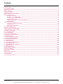

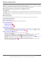
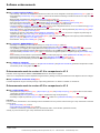
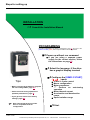
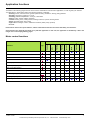
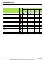
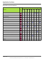
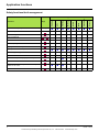
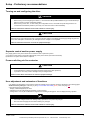
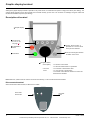
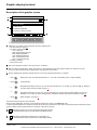
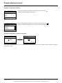
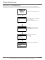
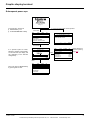
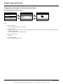
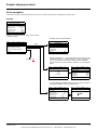
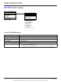
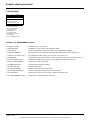
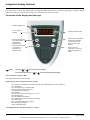
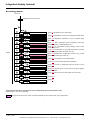
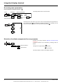
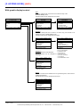
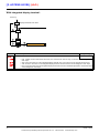
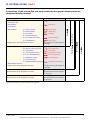
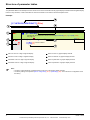
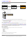
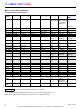
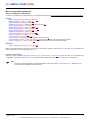
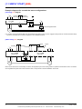
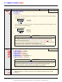
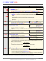
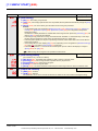
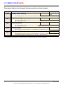
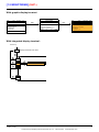
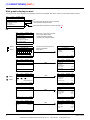
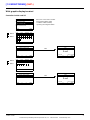
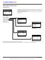
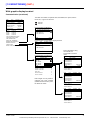
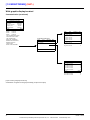
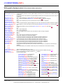
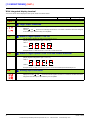
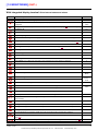
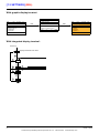
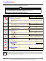
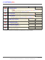
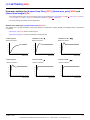
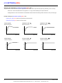
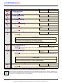
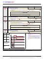
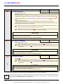
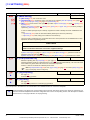
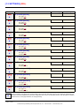
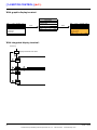
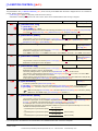
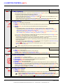
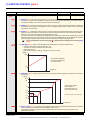
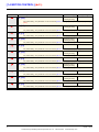
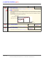
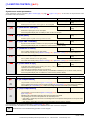
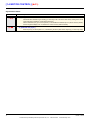
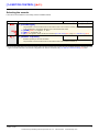
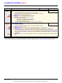
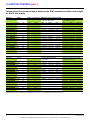
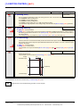
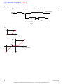
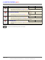
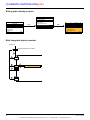
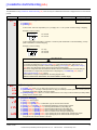

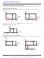
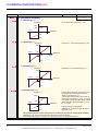
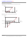
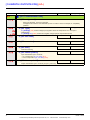
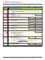
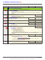
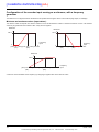
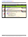
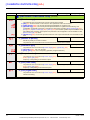
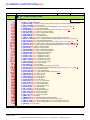
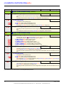
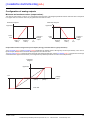
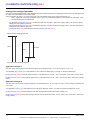
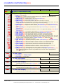
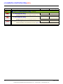
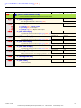
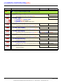
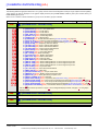
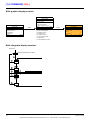
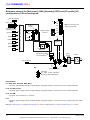
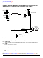
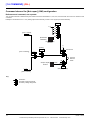
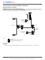
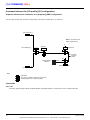
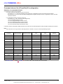
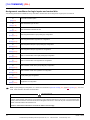
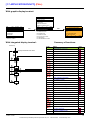

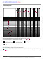
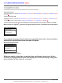
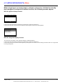
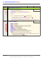
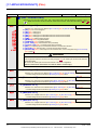
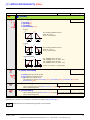
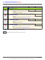

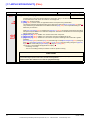
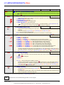
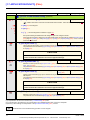
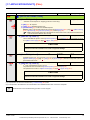
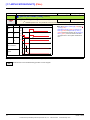
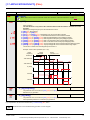
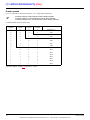
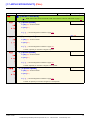
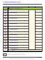
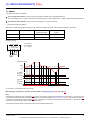
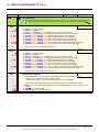
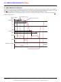
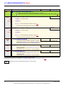
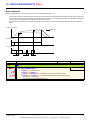
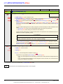
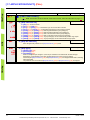
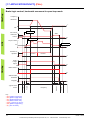
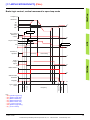
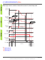
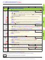
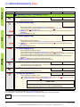
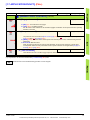
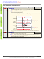
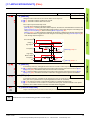
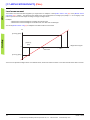
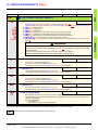
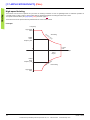
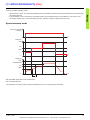
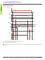
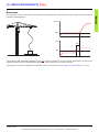
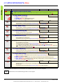
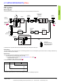
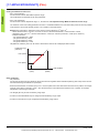
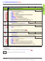
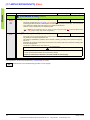
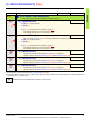
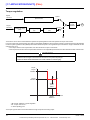
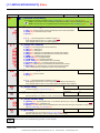
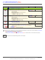
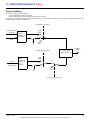
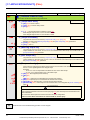
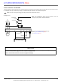
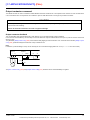
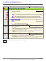
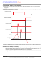
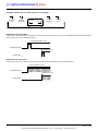
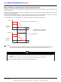
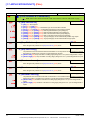
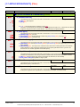
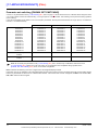
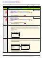
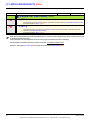
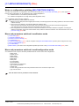
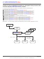
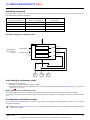
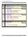
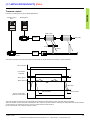
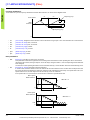
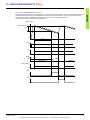
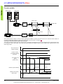
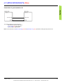
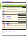
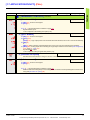
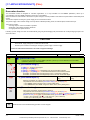
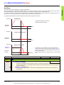
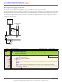
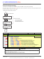
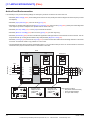
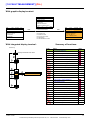
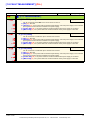
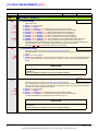
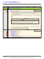
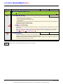
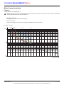
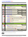
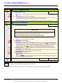
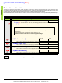
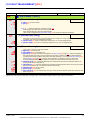
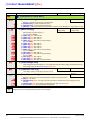
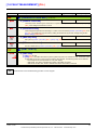
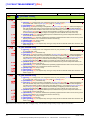
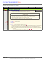
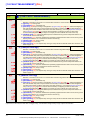
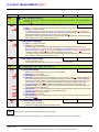

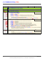
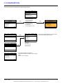
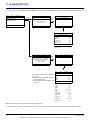
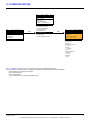
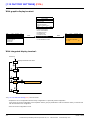
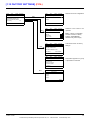
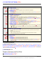
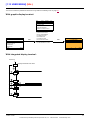
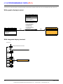
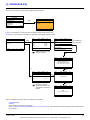
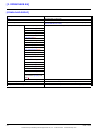
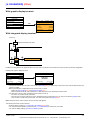
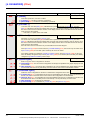
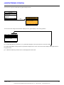
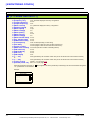
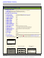
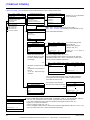
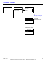
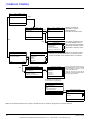
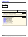
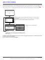

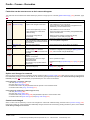
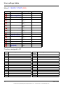
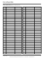
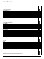
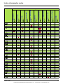
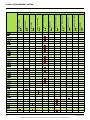
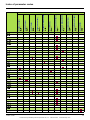
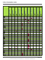
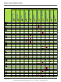
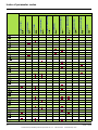
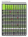
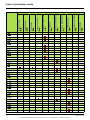
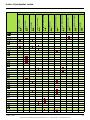
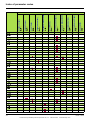
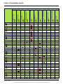
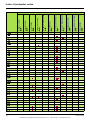
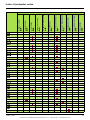
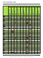
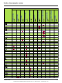
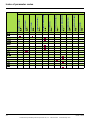

![[1.7 APPLICATION FUNCT.] (FUn](http://vs1.manualzilla.com/store/data/005865551_1-ec59525967aac13e1fcb9d41d71413ed-150x150.png)
![[1.7 APPLICATION FUNCT.] (FUn](http://vs1.manualzilla.com/store/data/005795769_1-62115863bd572564b923fbca39341baa-150x150.png)