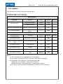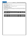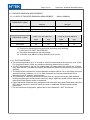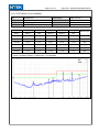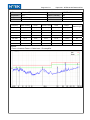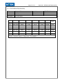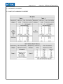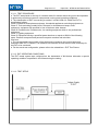
1
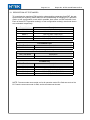
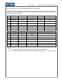
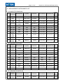
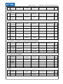
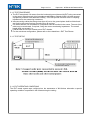
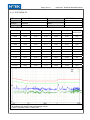
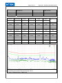
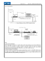
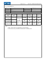
EMC TEST REPORT
ETSI EN 301 489-01 V1.9.2(2011-09)
E TSI EN 301 489-17 V2.2.1(2012-09)
Product: Wireless AP
Trade Name: N/A
Model Name: WNP-RP-002
Serial Model: WT-U26, JWA-N2308
Report No.: NTEK-2013NT0905144E-01
Prepared for
Gembird Europe B.V.
Wittevrouwen 56, 1358 CD, Almere Haven, The Netherlands
Prepared by
Shenzhen NTEK Testing Technology Co., Ltd.
1/F, Building E, Fenda Science Park, Sanwei Community, Xixiang Street
Bao’an District, Shenzhen P.R. China
Tel.: +86-0755-61156588 Fax.: +86-0755-61156599
Website:www.ntek.org.cn
Page 3 of 47
Report No.: NTEK-2013NT0905144E-01
Table of Contents
Page
1 . TEST SUMMARY
5
1.1 TEST FACILITY
6
1.2 MEASUREMENT UNCERTAINTY
6
2 . GENERAL INFORMATION
7
2.1 DESCRIPTION OF TEST MODES
8
2.2 DESCRIPTION OF TEST SETUP
9
2.3 DESCRIPTION TEST PERIPHERAL AND EUT PERIPHERAL
10
2.4 MEASUREMENT INSTRUMENTS LIST
11
3 . EMC EMISSION TEST
3.1
CONDUCTED EMISSION MEASUREMENT
3.1.1 POWER LINE CONDUCTED EMISSION
3.1.2 TEST PROCEDURE
3.1.3 TEST SETUP
3.1.4 EUT OPERATING CONDITIONS
3.1.5 TEST RESULTS
13
13
13
14
14
14
15
3.2 RADIATED EMISSION MEASUREMENT
3.2.1 LIMITS OF RADIATED EMISSION MEASUREMENT
3.2.2 LIMITS OF RADIATED EMISSION MEASUREMENT
3.2.3 TEST PROCEDURE
3.2.4 TEST SETUP
3.2.5 EUT OPERATING CONDITIONS
3.2.6 TEST RESULTS (30-1000MHz)
3.2.7 TEST RESULTS(1000-6000)
17
17
17
17
18
18
19
21
3.3 HARMONICS CURRENT
3.3.1 LIMITS OF HARMONICS CURRENT
3.3.1.1 TEST PROCEDURE
3.3.1.2 EUT OPERATING CONDITIONS
3.3.1.3 TEST SETUP
3.3.2 TEST RESULTS
22
22
23
23
23
24
3.4 VOLTAGE FLUCTUATION AND FLICKERS
3.4.1 LIMITS OF VOLTAGE FLUCTUATION AND FLICKERS
3.4.1.1 TEST PROCEDURE
3.4.1.2 EUT OPERATING CONDITIONS
3.4.1.3 TEST SETUP
3.4.2 TEST RESULTS
25
25
25
25
25
26
4 . EMC IMMUNITY TEST
4.1 GENERAL PERFORMANCE CRITERIA
27
27
Page 4 of 47
Report No.: NTEK-2013NT0905144E-01
Table of Contents
4.1.1 PERFORMANCE CRITERIA(WCDMA)
4.1.2 PERFORMANCE CRITERIA
Page
27
28
4.2 GENERAL PERFORMANCE CRITERIA TEST SETUP
29
4.3 ESD TESTING
4.3.1 TEST SPECIFICATION
4.3.2 TEST PROCEDURE
4.3.3 TEST SETUP
4.3.4 TEST RESULTS
4.3.5 PHOTO(S) SHOWN THE LOCATION(S) OF ESD EVALUATED
30
30
30
31
32
33
4.4 RS TESTING
4.4.1 TEST SPECIFICATION
4.4.2 TEST PROCEDURE
4.4.3 TEST SETUP
4.4.4 TEST RESULTS
34
34
34
35
36
4.5 EFT/BURST TESTING
4.5.1 TEST SPECIFICATION
4.5.2 TEST PROCEDURE
4.5.3 TEST SETUP
4.5.4 TEST RESULTS
37
37
37
38
39
4.6 SURGE TESTING
4.6.1 TEST SPECIFICATION
4.6.2 TEST PROCEDURE
4.6.3 TEST SETUP
4.6.4 TEST RESULTS
40
40
40
41
42
4.7 INJECTION CURRENT TESTING
4.7.1 TEST SPECIFICATION
4.7.2 TEST PROCEDURE
4.7.3 TEST SETUP
4.7.4 TEST RESULTS
43
43
43
43
44
4.8 VOLTAGE INTERRUPTION/DIPS TESTING
4.8.1 TEST SPECIFICATION
4.8.2 TEST PROCEDURE
4.8.3 TEST SETUP
4.8.4 TEST RESULTS
45
45
45
45
46
5 . EUT TEST PHOTO
47
Page 5 of 47
Report No.: NTEK-2013NT0905144E-01
1. TEST SUMMARY
Test procedures according to the technical standards:
ETSI EN 301 489-01 V1.9.2(2011-09)
ETSI EN 301 489-17 V2.2.1 (2012-09)
EMC Emission
Standard
Test Item
Limit
Judgment
Conducted Emission
Class B
PASS
Radiated Emission
Class B
PASS
Remark
EN 55022:2010
A or D
EN61000-3-2:2006+A2:2009 Harmonic Current Emission Class
NOTE (2)
EN 61000-3-3:2008
Voltage Fluctuations &
Flicker
N/A
------
PASS
EMC Immunity
Section
EN 55024:2010
Test Item
Performance
Criteria
Judgment
EN 61000-4-2:2009
Electrostatic Discharge
B
PASS
EN
61000-4-3:2006+A1:2008+A2: RF electromagnetic field
2010
A
PASS
EN 61000-4-4:2012
Fast transients
B
PASS
EN 61000-4-5:2006
Surges
B
PASS
EN 61000-4-6:2012
Injected Current
A
PASS
EN 61000-4-11:2004
Volt. Interruptions Volt.
Dips
B/C/C
PASS
NOTE (3)
NOTE:
(1)” N/A” denotes test is not applicable in this Test Report
(2) The power consumption of EUT is less than 75W and no Limits apply.
(3) Voltage dip: 100% reduction – Performance Criteria B
Voltage dip: 30% reduction – Performance Criteria C
Voltage Interruption: 100% Interruption – Performance Criteria C
(4) For client’s request and manual description, the test will not be executed.
Remark
Page 6 of 47
Report No.: NTEK-2013NT0905144E-01
1.1 TEST FACILITY
NTEK Testing Technology Co., Ltd.
Add. : 1/F, Building E, Fenda Science Park, Sanwei Community, Xixiang Street, Bao’ an District,
Shenzhen P.R. China
FCC Registered No.: 238937 IC Registered No.:9270A-1
CNAS Registered No.:L5516
1.2 MEASUREMENT UNCERTAINTY
The reported uncertainty of measurement y ± U,where expended uncertainty U is based on a
standard uncertainty multiplied by a coverage factor of k=2,providing a level of confidence of
approximately 95 %。
A. Conducted Measurement :
Test Site Method
NTEKC01 ANSI
Measurement Frequency Range
150 KHz ~ 30MHz
U,(dB)
3.2
NOTE
U,(dB)
4.7
5.0
NOTE
B. Radiated Measurement :
Test Site Method
NTEKA01 ANSI
Measurement Frequency Range
30MHz ~ 1000MHz
1GHz ~6000GHz
Page 7 of 47
Report No.: NTEK-2013NT0905144E-01
2. GENERAL INFORMATION
2.1 GENERAL DESCRIPTION OF EUT
Equipment
Wireless AP
Trade Name
N/A
Model Name
WNP-RP-002
Serial Model
WT-U26, JWA-N2308
All the models are the same circuit and RF module,
except the model names and colours.
802.11b/g/n(20MHz): 2412~2472MHz
Model Difference
Frequency Bands:
802.11n(40MHz):2422~2462MHz
Modulation Mode:
CCK/OFDM/DBPSK/DAPSK
Power Rating
AC 230V/50Hz
Adapter
N/A
Battery
N/A
Antenna:
FPCB Antenna
Connecting I/O Port(s)
Please refer to the User's Manual
Hard Ware Version
--
Note:
1. For a more detailed features description, please refer to the manufacturer’s specifications
or the User's Manual.
Page 8 of 47
Report No.: NTEK-2013NT0905144E-01
2.1 DESCRIPTION OF TEST MODES
To investigate the maximum EMI emission characteristics generates from EUT, the test
system was pre-scanning tested base on the consideration of following EUT operation
mode or test configuration mode which possible have effect on EMI emission level.
Each of these EUT operation mode(s) or test configuration mode(s) mentioned above
was evaluated respectively.
Pretest Mode
Mode 1
Mode 2
Mode 3
Mode 4
Mode 5
Description
Link Mode
802.11b CH1/ CH6/ CH11
802.11g CH1/ CH6/ CH11
802.11n(20) CH1/ CH6/ CH11
802.11n(40) CH3/ CH6/ CH9
For Radiated Test
Final Test Mode
Mode 1
Description
Link mode
For Conducted Emission Test
Final Test Mode
Mode 1
Description
Link mode
For EMS Test
Final Test Mode
Mode 1
Mode 2
Mode 3
Mode 4
Mode 5
Description
Link Mode
802.11b CH1/ CH6/ CH11
802.11g CH1/ CH6/ CH11
802.11n(20) CH1/ CH6/ CH11
802.11n(40) CH3/ CH6/ CH9
NOTE: The test modes were carried out for all operation modes.The final test mode of the
EUT was the worst test mode for EMI, and its test data was showed.
Page 9 of 47
Report No.: NTEK-2013NT0905144E-01
2.2 DESCRIPTION OF TEST SETUP
AC Plug
C-1
E-2
Notebook
E-1
EUT
Page 10 of 47
Report No.: NTEK-2013NT0905144E-01
2.3 DESCRIPTION TEST PERIPHERAL AND EUT PERIPHERAL
The EUT has been tested as an independent unit together with other necessary accessories or
support units. The following support units or accessories were used to form a representative test
configuration during the tests.
Item
Equipment
Brand
Model/Type No.
Series No.
Note
E-1
Wireless AP
N/A
WNP-RP-002
H-4, H-4Q
EUT
E-2
Notebook
Dell
PP10L
N/A
N/A
Item
Shielded Type
Ferrite Core
Length
C-1
NO
NO
80cm
Note
Note:
(1)
(2)
The support equipment was authorized by Declaration of Confirmation.
For detachable type I/O cable should be specified the length in cm in『Length』column.
Page 11 of 47
Report No.: NTEK-2013NT0905144E-01
2.4 MEASUREMENT INSTRUMENTS LIST
2.4.1CONDUCTED EMISSION
Item
1
2
3
4
Kind of
Manufacturer
Equipment
LISN
R&S
SCHWARZBE
CK
Pulse
SCHWARZBE
Limiter
CK
ANRITSU
50Ω Switch
CORP
LISN
Last calibration Calibrated until
Calibra
tion
period
Type No.
Serial No.
ENV216
101313
Jul. 06, 2013
NNLK 8129
8129245
Dec. 25, 2012 Dec. 24, 2013 1 year
VTSD 9561F
9716
Dec. 25, 2012 Dec. 24, 2013 1 year
MP59B
6200983704
Jul. 06, 2013
Jul. 05, 2014
1 year
Jul. 05, 2014
1 year
5
Test Cable
N/A
C01
N/A
Jul. 06, 2013
Jul. 05, 2014
1 year
6
Test Cable
N/A
C02
N/A
Jul. 06, 2013
Jul. 05, 2014
1 year
7
Test Cable
N/A
C03
N/A
Jul. 06, 2013
Jul. 05, 2014
1 year
R&S
ESCI
101160
Jul. 06, 2013
Jul. 05, 2014
1 year
ESH2-Z3
R&S
100196
Jul. 06, 2013
Jul. 05, 2014
1 year
EVERFINE
LIA-2
11020003
Jul. 06, 2013
Jul. 05, 2014
1 year
R&S
MDS-21
100423
Jul. 08, 2013
Jul. 07, 2014
1 year
Type No.
Serial No.
EMI Test
Receiver
Passive
Voltage
9
Probe
Triple-Loop
10
Antenna
Absorbing
11
Clamp
8
2.4.2 RADIATED TEST SITE
Item
Kind of
Manufacturer
Equipment
Last calibration Calibrated until
Calibra
tion
period
1
Bilog
Antenna
TESEQ
CBL6111D
31216
2
Test Cable
N/A
R-01
N/A
Dec. 25, 2012 Dec. 24, 2013 1 year
3
Test Cable
N/A
R-02
N/A
Dec. 25, 2012 Dec. 24, 2013 1 year
R&S
ESCI-7
101318
Jul. 06, 2013
Jul. 05, 2014
1 year
EM
SC100_1
N/A
N/A
N/A
N/A
EM
SC100
060531
N/A
N/A
N/A
MP59B
6200983705
Jul. 06, 2013
Jul. 05, 2014
1 year
Aglient
E4407B
MY45108040
Jul. 06, 2013
Jul. 05, 2014
1 year
EM
EM-AH-10180
2011071402
Jul. 06, 2013
Jul. 05, 2014
1 year
EM
EM-30180
060538
Jul. 06, 2013
Jul. 05, 2014
1 year
Kind of
Manufacturer
Equipment
Type No.
Serial No.
Harmonic
& Flicker
DPA500
0303-04
4
5
EMI Test
Receiver
Antenna
Mast
6
Turn Table
7
50Ω Switch Anritsu Corp
8
9
10
Spectrum
Analyzer
Horn
Antenna
Amplifier
Jul. 06, 2013
Jul. 05, 2014
1 year
2.4.3 HARMONICS AND FILCK
Item
1
EM TEST
Last calibration Calibrated until
Jul. 06, 2013
Jul. 05, 2014
Calibra
tion
period
1 year
Page 12 of 47
2
AC Power
Source
EM TEST
ACS500
0203-01
Report No.: NTEK-2013NT0905144E-01
Jul. 06, 2013
Jul. 05, 2014
1 year
2.4.4 ESD
Calibra
tion
period
Item
Kind of
Manufacturer
Equipment
Type No.
Serial No.
1
ESD TEST
GENERAT SCHAFFNER
OR
NSG438
859
Type No.
Serial No.
SMT 06
832080/007
VULB9161
4022
Aug. 15, 2013 Aug. 14, 2014 1 year
150W1000M1
320946
Sep. 23, 2012 Sep. 22, 2013 1 year
AT4002A
321467
Jun. 11, 2013
25S1G4A
308598
Sep. 23, 2012 Sep. 22, 2013 1 year
Last calibration Calibrated until
Jul. 06, 2013
Jul. 05, 2014
1 year
2.4.5 RS
Item
1
2
3
4
5
Kind of
Manufacturer
Equipment
Signal
R&S
Generator
Log-Bicon
Schwarzbeck
Antenna
Power
AR
Amplifier
Microwave
Horn
AR
Antenna
Power
AR
Amplifier
Last calibration Calibrated until
Jul. 24, 2013
Jul. 23, 2014
Calibra
tion
period
1 year
Jun. 10, 2014 1 year
2.4.6 SURGE, EFT/BURST, VOLTAGE INTERRUPTION/DIPS
Item
1
2
3
Kind of
Manufacturer
Equipment
Surge
Generator
DIPS
Generator
EFT/B
Generator
Serial No.
EMS61000-5A
1101002
Jul. 06, 2013
Jul. 05, 2014
1 year
1011002
Jul. 06, 2013
Jul. 05, 2014
1 year
1012005
Aug. 04, 2013 Aug. 03, 2014 1 year
Type No.
Serial No.
Last calibration Calibrated until
IFR
2023A
202301/368
AR
75A250AM1
0320709
EVERFINE
EVERFINE
EVERFINE
EMS61000-11
K
EMS61000-4AV2
Last calibration Calibrated until
Calibra
tion
period
Type No.
2.4.7 INJECTION CURRENT
Item
1
2
Kind of
Manufacturer
Equipment
Signal
Generator
Power
Amplifier
Mar. 31, 2013
Calibra
tion
period
Mar. 30, 2014 1 year
Sep. 23, 2012 Sep. 22, 2013 1 year
3
CDN
FCC
FCC-801-M2
06043
Jun. 02, 2013
Jun. 01, 2014 1 year
4
EM Clamp
FCC
F-203I-23MM
504
Jun. 09, 2013
Jun. 08, 2014 1 year
Type No.
Serial No.
EMS61000-8K
1007001
2.4.8 MF
Item
1
Kind of
Manufacturer
Equipment
Generator
EVERFINE
Last calibration Calibrated until
Jul. 06, 2013
Jul. 05, 2014
Calibra
tion
period
1 year
Page 13 of 47
Report No.: NTEK-2013NT0905144E-01
3. EMC EMISSION TEST
3.1 CONDUCTED EMISSION MEASUREMENT
3.1.1 POWER LINE CONDUCTED EMISSION (Frequency Range 150KHz-30MHz)
FREQUENCY (MHz)
Class A (dBuV)
Class B (dBuV)
Quasi-peak
Average
Quasi-peak
Average
0.15 -0.5
79.00
66.00
66 - 56 *
56 - 46 *
0.50 -5.0
73.00
60.00
56.00
46.00
73.00
60.00
60.00
50.00
5.0 -30.0
Note:
(1) The tighter limit applies at the band edges.
(2) The limit of " * " marked band means the limitation decreases linearly with the
logarithm of the frequency in the range.
The following table is the setting of the receiver
Receiver Parameters
Attenuation
Start Frequency
Stop Frequency
IF Bandwidth
Setting
10 dB
0.15 MHz
30 MHz
9 kHz
Page 14 of 47
Report No.: NTEK-2013NT0905144E-01
3.1.2 TEST PROCEDURE
a. The EUT was placed 0.8 meters from the horizontal ground plane with EUT being connected
to the power mains through a line impedance stabilization network (LISN). All other support
equipments powered from additional LISN(s). The LISN provide 50 Ohm/ 50uH of coupling
impedance for the measuring instrument.
b. Interconnecting cables that hang closer than 40 cm to the ground plane shall be folded back
and forth in the center forming a bundle 30 to 40 cm long.
c. I/O cables that are not connected to a peripheral shall be bundled in the center. The end of the
cable may be terminated, if required, using the correct terminating impedance. The overall
length shall not exceed 1 m.
d. LISN at least 80 cm from nearest part of EUT chassis.
e. For the actual test configuration, please refer to the related Item –EUT Test Photos.
3.1.3 TEST SETUP
3.1.4 EUT OPERATING CONDITIONS
The EUT tested system was configured as the statements of 2.2 Unless otherwise a special
operating condition is specified in the follows during the testing.
Page 15 of 47
Report No.: NTEK-2013NT0905144E-01
3.1.5 TEST RESULTS
EUT:
Wireless AP
Temperature: 26 ℃
Pressure:
1010hPa
Test Voltage :AC 230V/50Hz
Model Name. :
Relative Humidity:
Phase :
Test Mode:
WNP-RP-002
54%
L
Mode 1
Frequency
Meter Reading
Factor
Emission Level
Limits
Margin
(MHz)
(dBμV)
(dB)
(dBμV/m)
(dBμV/m)
(dB)
0.2060
26.86
10.69
37.55
63.36
-25.81
QP
0.2060
10.88
10.69
21.57
53.36
-31.79
AVG
0.4420
26.96
10.65
37.61
57.02
-19.41
QP
0.4420
16.06
10.65
26.71
47.02
-20.31
AVG
0.8780
25.31
10.53
35.84
56.00
-20.16
QP
0.8780
8.93
10.53
19.46
46.00
-26.54
AVG
5.4618
33.31
10.66
43.97
60.00
-16.03
QP
5.4618
13.93
10.66
24.59
50.00
-25.41
AVG
7.7139
24.70
10.76
35.46
60.00
-24.54
QP
7.7139
10.02
10.76
20.78
50.00
-29.22
AVG
11.2219
22.81
10.86
33.67
60.00
-26.33
QP
11.2219
10.85
10.86
21.71
50.00
-28.29
AVG
Remark:
1. All readings are Quasi-Peak and Average values.
2. Factor = Insertion Loss + Cable Loss.
Detector Type
Page 16 of 47
EUT:
Temperature:
Pressure:
Test Voltage :
Wireless AP
26 ℃
1010hPa
AC 230V/50Hz
Report No.: NTEK-2013NT0905144E-01
Model Name. :
Relative Humidity:
Phase :
Test Mode:
WNP-RP-002
54%
N
Mode 1
Frequency
Meter Reading
Factor
Emission Level
Limits
Margin
(MHz)
(dBμV)
(dB)
(dBμV/m)
(dBμV/m)
(dB)
0.1580
22.55
11.36
33.91
65.56
-31.65
QP
0.1580
13.84
11.36
25.20
55.56
-30.36
AVG
0.4380
29.77
10.66
40.43
57.10
-16.67
QP
0.4380
24.08
10.66
34.74
47.10
-12.36
AVG
1.7380
26.88
10.52
37.40
56.00
-18.60
QP
1.7380
13.80
10.52
24.32
46.00
-21.68
AVG
5.4339
36.46
10.66
47.12
60.00
-12.88
QP
5.4339
15.82
10.66
26.48
50.00
-23.52
AVG
7.6699
27.92
10.76
38.68
60.00
-21.32
QP
7.6699
11.22
10.76
21.98
50.00
-28.02
AVG
11.3579
24.06
10.86
34.92
60.00
-25.08
QP
11.3579
12.48
10.86
23.34
50.00
-26.66
AVG
Remark:
1. All readings are Quasi-Peak and Average values.
2. Factor = Insertion Loss + Cable Loss.
Detector Type
Page 17 of 47
Report No.: NTEK-2013NT0905144E-01
3.2 RADIATED EMISSION MEASUREMENT
3.2.1 LIMITS OF RADIATED EMISSION MEASUREMENT
FREQUENCY (MHz)
Class A (at 10m)
Class B (at 10m)
dBuV/m
dBuV/m
40
30
30 – 230
230 – 1000
47
3.2.2 LIMITS OF RADIATED EMISSION MEASUREMENT
FREQUENCY (MHz)
1000-3000
(Below 1000MHz)
Class A (at 10m) dBuV/m
37
(Above 1000MHz)
Class B (at 10m) dBuV/m
Peak
Avg
Peak
Avg
76
56
70
50
3000-6000
80
60
74
Notes:
(1) The limit for radiated test was performed according to as following:
CISPR 22/ FCC PART 15B /ICES-003.
(2) The tighter limit applies at the band edges.
(3) Emission level (dBuV/m)=20log Emission level (uV/m).
54
3.2.3 TEST PROCEDURE
a. The measuring distance of at 10 m shall be used for measurements at frequency up to 1GHz.
For frequencies above 1GHz, any suitable measuring distance may be used.
b. The EUT was placed on the top of a rotating table 0.8 meters above the ground at a 10 meter
open area test site. The table was rotated 360 degrees to determine the position of the highest
radiation.
c. The height of the equipment or of the substitution antenna shall be 0.8 m; the height of the test
antenna shall vary between 1 m to 4 m. Both horizontal and vertical polarizations of the
antenna are set to make the measurement.
d. The initial step in collecting conducted emission data is a spectrum analyzer peak detector
mode pre-scanning the measurement frequency range. Significant peaks are then marked and
then Quasi Peak detector mode re-measured.
e. If the Peak Mode measured value compliance with and lower than Quasi Peak Mode Limit, the
EUT shall be deemed to meet QP Limits and then no additional QP Mode measurement
performed.
f. For the actual test configuration, please refer to the related Item –EUT Test Photos.
Page 18 of 47
Report No.: NTEK-2013NT0905144E-01
3.2.4 TEST SETUP
(A) Radiated Emission Test Set-Up Frequency Below 1 GHz
(B) Radiated Emission Test Set-Up Frequency Above 1GHz
3.2.5 EUT OPERATING CONDITIONS
The EUT tested system was configured as the statements of 2.2 Unless otherwise a special
operating condition is specified in the follows during the testing.
Page 19 of 47
Report No.: NTEK-2013NT0905144E-01
3.2.6 TEST RESULTS (30-1000MHz)
EUT:
Temperature:
Pressure:
Test Power :
Model Name :
Relative Humidity:
Polarization :
Test Mode :
Wireless AP
24 ℃
1010 hPa
AC 230V/50Hz
WNP-RP-002
54%
Horizontal
Mode 1
Frequency
Meter Reading
Factor
Emission Level
Limits
Margin
(MHz)
(dBμV)
(dB)
(dBμV/m)
(dBμV/m)
(dB)
74.3954
16.71
6.73
23.44
40.00
-16.56
QP
156.4577
16.61
11.33
27.94
40.00
-12.06
QP
190.4050
20.50
9.01
29.51
40.00
-10.49
QP
311.0867
26.36
15.09
41.45
47.00
-5.55
QP
465.5994
22.00
19.59
41.59
47.00
-5.41
QP
665.8034
13.91
23.77
37.68
47.00
-9.32
QP
Remark:
1. Factor = Antenna Factor + Cable Loss – Pre-amplifier.
Detector Type
Page 20 of 47
EUT:
Temperature:
Pressure:
Test Power :
Report No.: NTEK-2013NT0905144E-01
Model Name :
WNP-RP-002
Relative Humidity: 54%
Polarization :
Vertical
Test Mode :
Mode 1
Wireless AP
24 ℃
1010 hPa
AC 230V/50Hz
Frequency
Meter Reading
Factor
Emission Level
Limits
Margin
(MHz)
(dBμV)
(dB)
(dBμV/m)
(dBμV/m)
(dB)
36.1272
18.34
15.31
33.65
40.00
-6.35
QP
43.6584
21.98
11.34
33.32
40.00
-6.68
QP
141.3298
21.06
12.13
33.19
40.00
-6.81
QP
311.0867
18.15
15.09
33.24
47.00
-13.76
QP
465.5994
23.96
19.59
43.55
47.00
-3.45
QP
896.9964
13.62
27.75
41.37
47.00
-5.63
QP
Remark:
1. Factor = Antenna Factor + Cable Loss – Pre-amplifier.
Detector Type
Page 21 of 47
Report No.: NTEK-2013NT0905144E-01
3.2.7 TEST RESULTS(1000-6000)
EUT:
Temperature:
Pressure:
Test Power :
Model Name :
Relative Humidity:
Test Mode :
Wireless AP
24 ℃
1010 hPa
AC 230V/50Hz
WNP-RP-002
54%
Mode 1
Polar
Frequency
Meter Reading
Factor
Emission Level
Limits
Margin
(H/V)
(MHz)
(dBμV)
(dB)
(dBμV/m)
(dBμV/m)
(dB)
Detector
Type
V
1752.1100
59.39
-15.29
44.10
70.00
-25.90
peak
V
3142.2350
59.59
-11.39
48.20
74.00
-25.80
peak
V
5340.3710
53.96
-4.56
49.40
74.00
-24.60
peak
H
1562.2830
59.43
-16.73
42.70
70.00
-27.30
peak
H
2655.1710
58.84
-12.04
46.80
70.00
-23.20
peak
H
3882.0440
53.62
-7.12
46.50
74.00
-27.50
peak
Remark:
1. Factor = Antenna Factor + Cable Loss – Pre-amplifier.
Page 22 of 47
3.3 HARMONICS CURRENT
3.3.1LIMITS OF HARMONICS CURRENT
Report No.: NTEK-2013NT0905144E-01
Page 23 of 47
Report No.: NTEK-2013NT0905144E-01
3.3.1.1 TEST PROCEDURE
a. The EUT was placed on the top of a wooden table 0.8 meters above the ground and operated
to produce the maximum harmonic components under normal operating conditions.
b. The classification of EUT is according to section 5 of EN 61000-3-2: 2000.The EUT is
classified as follows:
Class A: Balanced three-phase equipment, Household appliances excluding equipment as
Class D, Tools excluding portable tools, Dimmers for incandescent lamps, audio
equipment, equipment not specified in one of the three other classes.
Class B: Portable tools. Portable tools.; Arc welding equipment which is not professional
equipment.
Class C: Lighting equipment.
Class D: Equipment having a specified power less than or equal to 600W of the following
types: Personal computers and personal computer monitors and television
receivers.
c. The correspondent test program of test instrument to measure the current harmonics
emanated from EUT is chosen. The measure time shall be not less than the time necessary for
the EUT to be exercised.
d. For the actual test configuration, please refer to the related item –EUT Test Photos.
3.3.1.2 EUT OPERATING CONDITIONS
The EUT tested system was configured as the statements of 2.2 Unless otherwise a special
operating condition is specified in the follows during the testing.
3.3.1.3 TEST SETUP
Page 24 of 47
Report No.: NTEK-2013NT0905144E-01
3.3.2 TEST RESULTS
EUT:
Temperature:
Pressure:
Test Mode
Wireless AP
25 ℃
1010 hPa
N/A
Model Name :
WNP-RP-002
Relative Humidity: 45%
Test Power :
N/A
Note: The active input power of the EUT is less than 75 W. No limits apply for equipment with an
active input power up to and including 75W
Page 25 of 47
Report No.: NTEK-2013NT0905144E-01
3.4 VOLTAGE FLUCTUATION AND FLICKERS
3.4.1 LIMITS OF VOLTAGE FLUCTUATION AND FLICKERS
3.4.1.1TEST PROCEDURE
a. Harmonic Current Test:
Test was performed according to the procedures specified in Clause 5.0 of IEC555-2 and/or
Sub-clause 6.2 of IEC/EN 61000-3-2 depend on which standard adopted for compliance
measurement.
b. Fluctuation and Flickers Test:
Tests was performed according to the Test Conditions/Assessment of Voltage Fluctuations
specified in Clause 5.0/6.0 of IEC555-3 and/or Clause 6.0/4.0 of IEC/EN 61000-3-3 depend on
which standard adopted for compliance measurement.
c. All types of harmonic current and/or voltage fluctuation in this report are assessed by direct
measurement using flicker-meter.
d. For the actual test configuration, please refer to the related Item –EUT Test Photos.
3.4.1.2 EUT OPERATING CONDITIONS
The EUT tested system was configured as the statements of 2.2 Unless otherwise a special
operating condition is specified in the follows during the testing.
3.4.1.3 TEST SETUP
Page 26 of 47
Report No.: NTEK-2013NT0905144E-01
3.4.2 TEST RESULTS
EUT:
Temperature:
Pressure:
Test Mode
Model Name :
WNP-RP-002
Relative Humidity: 45%
Test Power :
AC 230V/50Hz
Wireless AP
25 ℃
1010 hPa
Mode1/2/3/4/5
Test Parameter
Measurement Value
Limit
Remarks
Pst
0.007
1.0
Pass
Plt
0.005
0.65
Pass
Tdt(s)
0.003
0.2
Pass
dmax(%)
0.00%
4%
Pass
dc(%)
0.00%
3%
Pass
Page 27 of 47
Report No.: NTEK-2013NT0905144E-01
4. EMC IMMUNITY TEST
4.1 GENERAL PERFORMANCE CRITERIA
4.1.1 PERFORMANCE CRITERIA(WCDMA)
According to EN 301489 -7 standard, the general performance criteria as following:
The apparatus shall continue to operate as intended during and after the test. No
Criterion A
degradation of performance or loss of function is allowed below a performance level
specified by the manufacturer, when the apparatus is used as intended.
Criterion B
The apparatus shall continue to operate as intended after the test. No degradation of
performance or loss of function is allowed below a performance level specified by the
manufacturer, when the apparatus is used as intended.
Criterion C
Temporary loss of function is allowed, provided the function is self-recoverable or
can be restored by the operation of the controls.
PERFORMANCE CRITERIA FOR CT AND CR
A communication link shall be established at the start of the test, and maintained during the test. During
the test, the RXQUAL of the downlink shall not exceed 3, measured during each individual exposure in
the test sequence. Both the uplink speech output level and the downlink speech output level shall be at
least 35 dB less than the previously recorded reference levels, when measured through an audio band
Pass filter of width 200 Hz, centered on 1 kHz (audio breakthrough check). At the conclusion of the test,
the EUT shall operate as intended with no loss of user control functions or stored data, and the
communication link shall have been maintained.
PERFORMANCE CRITERIA FOR TT AND TR
A communications link shall be established at the start of the test. At the conclusion of each exposure
the EUT shall operate with no user noticeable loss of the communication link. At the conclusion of the
total test comprising the series of individual exposures, the EUT shall operate as intended with no loss
of user control functions or stored data, as declared by the manufacturer, and the communication link
shall have been maintained.
According to EN 301489 -24 standard.
PERFORMANCE CRITERIA FOR CONTINUOUS PHENOMENA TO WCDMA
In the speech mode, the performance criteria shall be that the Up Link and Down Link speech output levels
shall be at least 35 dB less than the recorded reference levels, when measured through an audio band pass
filter of width 200 Hz,centred on 1 kHz.
PERFORMANCE CRITERIA FOR TRANSIENT PHENOMENA TO WCDMA
At the conclusion of each exposure the EUT shall operate with no user noticeable loss of the communication
link.At the conclusion of the total test comprising the series of individual exposures, the EUT shall operate as
intended with no loss of user control functions or stored data, as declared by the manufacturer, and the
communication link shall have been maintained.
In addition to confirming the above performance in traffic mode, the test shall also be performed in idle mode,
and the transmitter shall not unintentionally operate.
Page 28 of 47
Report No.: NTEK-2013NT0905144E-01
4.1.2 PERFORMANCE CRITERIA
According to EN 301489 -17standard, the general performance criteria as following:
Criteria
During the test
After the test
A
Shall operate as intended May show
degradation of performance (see note 1)
Shall be no loss of function Shall be no
unintentional transmissions
Shall operate as intended Shall be no
degradation of performance (see note 2)
Shall be no loss of function Shall be no
loss of stored data or user
programmable functions
B
May show loss of function (one or more)
May show degradation of performance
(see note 1) No unintentional
transmissions
Functions shall be self-recoverable Shall
operate as intended after recovering
Shall be no degradation of performance
(see note 2) Shall be no loss of stored
data or user programmable functions
May be loss of function (one or more)
Functions shall be recoverable by the
operator Shall operate as intended after
recovering Shall be no degradation of
performance (see note 2)
C
NOTE 1: Degradation of performance during the test is understood as a degradation to a level not
below a minimum performance level specified by the manufacturer for the use of the apparatus as
intended. In some cases the specified minimum performance level may be replaced by a
permissible degradation of performance. If the minimum performance level or the permissible
performance degradation is not specified by the manufacturer then either of these may be derived
from the product description and documentation (including leaflets and advertising) and what the
user may reasonably expect from the apparatus if used as intended.
NOTE 2: no degradation of performance after the test is understood as any degradation below a
minimum performance level specified by the manufacturer for the use of the apparatus as intended.
In some cases the specified minimum performance level may be replaced by a permissible
degradation of performance. After the test no change of actual operating data or user retrievable
data is allowed. If the minimum performance level or the permissible performance degradation is
not specified by the manufacturer then either of these may be derived from the product description
and documentation (including leaflets and advertising) and what the user may reasonably expect
from the apparatus if used as intended.
Page 29 of 47
Report No.: NTEK-2013NT0905144E-01
PERFORMANCE FOR TT
The performance criteria B shall apply, except for voltage dips of 100 ms and voltage interruptions of 5
000 ms duration, for which performance criteria C shall apply. Tests shall be repeated with the EUT in
standby mode (if applicable) to ensure that unintentional transmission does not occur. In systems using
acknowledgement signals, it is recognized that an acknowledgement (ACK) or not-acknowledgement
(NACK) transmission may occur, and steps should be taken to ensure that any transmission resulting
from the application of the test is correctly interpreted.
PERFORMANCE FOR TR
The performance criteria B shall apply, except for voltage dips of 100 ms and voltage interruptions of 5
000 ms duration for which performance criteria C shall apply. Where the EUT is a transceiver, under no
circumstances, shall the transmitter operate unintentionally during the test. In systems using
acknowledgement signals, it is recognized that an ACK or NACK transmission may occur, and steps
should be taken to ensure that any transmission resulting from the application of the test is correctly
interpreted.
PERFORMANCE FOR CT
The performance criteria A shall apply. Tests shall be repeated with the EUT in standby mode (if
applicable) to ensure that unintentional transmission does not occur. In systems using
acknowledgement signals, it is recognized that an Acknowledgement (ACK) or Not Acknowledgement
(NACK) transmission may occur, and steps should be taken to ensure that any transmission resulting
from the application of the test is correctly interpreted.
PERFORMANCE FOR CR
The performance criteria A shall apply. Where the EUT is a transceiver, under no circumstances, shall
the transmitter operate unintentionally during the test. In systems using acknowledgement signals, it is
recognized that an ACK or NACK transmission may occur, and steps should be taken to ensure that
any transmission resulting from the application of the test is correctly interpreted.
4.2 GENERAL PERFORMANCE CRITERIA TEST SETUP
The EUT tested system was configured as the statements of 2.2 Unless otherwise a special
operating condition is specified in the follows during the testing.
Page 30 of 47
Report No.: NTEK-2013NT0905144E-01
4.3 ESD TESTING
4.3.1 TEST SPECIFICATION
Basic Standard:
IEC/EN 61000-4-2
Discharge Impedance:
330 ohm / 150 pF
Required Performance
B
Discharge Voltage:
Air Discharge:2kV/4kV/8kV (Direct)
Contact Discharge:2kV/4kV (Direct/Indirect)
Polarity:
Positive & Negative
Number of Discharge:
Air Discharge: min. 20 times at each test point
Contact Discharge: min. 200 times in total
Discharge Mode:
AC Discharge
Discharge Period:
1 second minimum
4.3.2 TEST PROCEDURE
The test generator necessary to perform direct and indirect application of discharges to the EUT in
the following manner:
a. Contact discharge was applied to conductive surfaces and coupling planes of the EUT.
During the test, it was performed with single discharges. For the single discharge time
between successive single discharges was at least 1 second.
Vertical Coupling Plane (VCP):
The coupling plane, of dimensions 0.5m x 0.5m, is placed parallel to, and positioned at a
distance 0.1m from, the EUT, with the Discharge Electrode touching the coupling plane.
The four faces of the EUT will be performed with electrostatic discharge.
Horizontal Coupling Plane (HCP):
The coupling plane is placed under to the EUT. The generator shall be positioned vertically at
a distance of 0.1m from the EUT, with the Discharge Electrode touching the coupling plane.
The four faces of the EUT will be performed with electrostatic discharge.
b. Air discharges at insulation surfaces of the EUT.
It was at least ten single discharges with positive and negative at the same selected point.
c. For the actual test configuration, please refer to the related Item –EUT Test Photos.
Page 31 of 47
Report No.: NTEK-2013NT0905144E-01
4.3.3 TEST SETUP
Note:
TABLE-TOP EQUIPMENT
The configuration consisted of a wooden table 0.8 meters high standing on the Ground Reference
Plane. The GRP consisted of a sheet of aluminum at least 0.25mm thick, and 2.5 meters square
connected to the protective grounding system. A Horizontal Coupling Plane (1.6m x 0.8m) was
placed on the table and attached to the GRP by means of a cable with 940k total impedance. The
equipment under test, was installed in a representative system as described in section 7 of IEC
/EN 61000-4-2, and its cables were placed on the HCP and isolated by an insulating support of
0.5mm thickness. A distance of1-meter minimum was provided between the EUT and the walls of
the laboratory and any other metallic structure.
FLOOR-STANDING EQUIPMENT
The equipment under test was installed in a representative system as described in section 7 of
IEC/EN 61000-4-2, and its cables were isolated from the Ground Reference Plane by an
insulating support of 0.1-meter thickness. The GRP consisted of a sheet of aluminum that is at
least 0.25mm thick, and 2.5meters square connected to the protective grounding system and
extended at least 0.5 meters from the EUT on all sides.
Page 32 of 47
Report No.: NTEK-2013NT0905144E-01
4.3.4 TEST RESULTS
EUT:
Temperature:
Pressure:
Test Mode
Mode
Contact Discharge (Indirect)
Test level
(kV)
Test
Location
2
4
Criterion
6
Result
Test Point
HCP
VCP
+
-
+
-
Front
A
A
A
A
PASS
Rear
A
A
A
A
PASS
Left
A
A
A
A
PASS
Right
A
A
A
A
Front
A
A
A
A
Rear
A
A
A
A
PASS
Left
A
A
A
A
PASS
Right
A
A
A
A
PASS
Mode
Test level
(kV)
Test
Location
A1
A2
A3
Model Name :
WNP-RP-002
Relative Humidity: 45%
Test Power :
AC 230V/50Hz
Wireless AP
25 ℃
1010 hPa
Mode1/2/3/4/5
Air Discharge
2
+
4
-
+
8
-
+
A A A A A A
A A A A A A
A A A A A A
-
B
PASS
PASS
Contact Discharge
15
-
+
+
2
-
+
4
-
+
6
-
+
Obser
vation
8
-
+
Criterion
Result
B
PASS
PASS
PASS
TT,TR
Page 33 of 47
Report No.: NTEK-2013NT0905144E-01
4.3.5 PHOTO(S) SHOWN THE LOCATION(S) OF ESD EVALUATED
A2
A1
A3
Page 34 of 47
Report No.: NTEK-2013NT0905144E-01
4.4 RS TESTING
4.4.1 TEST SPECIFICATION
Basic Standard:
IEC/EN 61000-4-3
Required Performance
A
Frequency Range:
80 MHz - 1000 MHz ,1400MHz-2700MHz
Field Strength:
3 V/m
Modulation:
1kHz Sine Wave, 80%, AM Modulation
Frequency Step:
1 % of fundamental
Polarity of Antenna:
Horizontal and Vertical
Test Distance:
3m
Antenna Height:
1.5 m
Dwell Time:
at least 3 seconds
4.4.2 TEST PROCEDURE
The EUT and support equipment, which are placed on a table that is 0.8 meter above ground and
the testing was performed in a fully-anechoic chamber.
The testing distance from antenna to the EUT was 3 meters.
The other condition as following manner:
a. The field strength level was 3V/m.
b. The frequency range is swept from 80 MHz to 1000 MHz, & 1400MHz - 2700MHz with the
signal 80%amplitude modulated with a 1kHz sine wave. The rate of sweep did not exceed 1.5x
10-3 decade/s. Where the frequency range is swept incrementally, the step size was 1% of
fundamental.
c. Sweep Frequency 900 MHz, with the Duty Cycle:1/8 and Modulation: Pulse 217 Hz(if
applicable)
d. The dwell time at each frequency shall be not less than the time necessary for the
EUT to be able to respond.
e. The test was performed with the EUT exposed to both vertically and horizontally
polarized fields on each of the four sides.
f. For the actual test configuration, please refer to the related Item –EUT Test Photos.
Page 35 of 47
Report No.: NTEK-2013NT0905144E-01
4.4.3 TEST SETUP
Note:
TABLE-TOP EQUIPMENT
The EUT installed in a representative system as described in section 7 of IEC/EN 61000-4-3 was
placed on a non-conductive table 0.8 meters in height. The system under test was connected to
the power and signal wire according to relevant installation instructions.
FLOOR-STANDING EQUIPMENT
The EUT installed in a representative system as described in section 7 of IEC/EN 61000-4-3 was
placed on a non-conductive wood support 0.1 meters in height. The system under test was
connected to the power and signal wire according to relevant installation instructions.
Page 36 of 47
Report No.: NTEK-2013NT0905144E-01
4.4.4 TEST RESULTS
EUT:
Temperature:
Pressure:
Test Mode
Wireless AP
25 ℃
1010 hPa
Mode 1/2/3/4/5
TEST RESULT
Frequency RF Field
R.F.
Range (MHz) Position Field Strength
Model Name :
WNP-RP-002
Relative Humidity: 45%
Test Power :
AC 230V/50Hz
Perform.
Azimuth Observation
Results Judgment
Criteria
Front
80~1000
1400-2700
3 V/m (rms)
H/V
Rear
AM Modulated
1000Hz, 80%
CT,CR
A
Left
Right
Note:
1) P/N denotes the Positive/Negative polarity of the output voltage.
2) N/A - denotes test is not applicable in this test report.
3) There was no change operated with initial operating during the test.
4) There was not any unintentional transmission in standby mode
A
PASS
Page 37 of 47
Report No.: NTEK-2013NT0905144E-01
4.5 EFT/BURST TESTING
4.5.1 TEST SPECIFICATION
Basic Standard:
IEC/EN 61000-4-4
Required Performance
B
Test Voltage:
Power Line:1 kV
Signal/Control Line:0.5 KV
Polarity:
Positive & Negative
Impulse Frequency:
5 kHz
Impulse Wave shape :
5/50 ns
Burst Duration:
15 ms
Burst Period:
300 ms
Test Duration:
Not less than 1 min.
4.5.2 TEST PROCEDURE
The EUT and support equipment, are placed on a table that is 0.8 meter above a metal ground
plane measured 1m*1m min. and 0.65mm thick min.
The other condition as following manner:
a. The length of power cord between the coupling device and the EUT should not exceed 1
meter.
b. Both positive and negative polarity discharges were applied.
c. The duration time of each test sequential was 1 minute
d. For the actual test configuration, please refer to the related Item –EUT Test Photos.
Page 38 of 47
Report No.: NTEK-2013NT0905144E-01
4.5.3 TEST SETUP
Note:
TABLE-TOP EQUIPMENT
The configuration consisted of a wooden table (0.8m high) standing on the Ground Reference
Plane. The GRP consisted of a sheet of aluminum (at least 0.25mm thick and 2.5m square)
connected to the protective grounding system. A minimum distance of 0.5m was provided
between the EUT and the walls of the laboratory or any other metallic structure.
FLOOR-STANDING EQUIPMENT
The EUT installed in a representative system as described in section 7 of IEC/EN 61000-4-4 and
its cables, were isolated from the Ground Reference Plane by an insulating support that is
0.1-meter thick. The GRP consisted of a sheet of aluminum (at least 0.25mm thick and 2.5m
square) connected to the protective grounding system.
Page 39 of 47
Report No.: NTEK-2013NT0905144E-01
4.5.4 TEST RESULTS
EUT:
Temperature:
Pressure:
Test Mode
Model Name :
Relative Humidity:
Test Power :
Wireless AP
25 ℃
1010 hPa
Mode1/2/3/4/5
WNP-RP-002
45%
AC 230V/50Hz
Test level (kV)
Coupling Line
AC
line
0.5
1
2
+
Observation Criterion Result
4
+
-
+
-
-
+
-
L
A
A
A
A
PASS
N
A
A
A
A
PASS
A
A
A
A
PASS
PE
L+N
L+PE
TT,TR
N+PE
L+N+PE
DC Line
Signal Line
Note:
1) P/N denotes the Positive/Negative polarity of the output voltage.
2) N/A - denotes test is not applicable in this test report
3) There was not any unintentional transmission in standby mode
B
Page 40 of 47
Report No.: NTEK-2013NT0905144E-01
4.6 SURGE TESTING
4.6.1 TEST SPECIFICATION
Basic Standard:
IEC/EN 61000-4-5
Required Performance
B
Wave-Shape:
Combination Wave
1.2/50 us Open Circuit Voltage
8 /20 us Short Circuit Current
Test Voltage:
Power Line:0.5 kV, 1 kV
Surge Input/Output:
L-N
Generator Source:
2 ohm between networks
Impedance:
12 ohm between network and ground
Polarity:
Positive/Negative
Phase Angle:
0 /90/180/270
Pulse Repetition Rate:
1 time / min. (maximum)
Number of Tests:
5 positive and 5 negative at selected points
4.6.2 TEST PROCEDURE
a. For EUT power supply:
The surge is to be applied to the EUT power supply terminals via the capacitive coupling
network. Decoupling networks are required in order to avoid possible adverse effects on
equipment not under test that may be powered by the same lines, and to provide sufficient
decoupling impedance to the surge wave. The power cord between the EUT and the
coupling/decoupling networks shall be 2meters in length (or shorter).
b. For test applied to unshielded unsymmetrically operated interconnection lines of EUT:
The surge is applied to the lines via the capacitive coupling. The coupling /decoupling
networks shall not influence the specified functional conditions of the EUT. The
interconnection line between the EUT and the coupling/decoupling networks shall be 2 meters
in length (or shorter).
c. For test applied to unshielded symmetrically operated interconnection /telecommunication
lines of EUT:
The surge is applied to the lines via gas arrestors coupling. Test levels below the ignition point
of the coupling arrestor cannot be specified. The interconnection line between the EUT and
the coupling/decoupling networks shall be 2 meters in length (or shorter).
d. For the actual test configuration, please refer to the related Item –EUT Test Photos.
Page 41 of 47
4.6.3 TEST SETUP
Report No.: NTEK-2013NT0905144E-01
Page 42 of 47
Report No.: NTEK-2013NT0905144E-01
4.6.4 TEST RESULTS
EUT:
Temperature:
Pressure:
Test Mode
Model Name :
WNP-RP-002
Relative Humidity: 45%
Test Power :
AC 230V/50Hz
Wireless AP
25 ℃
1010 hPa
Mode1/2/3/4/5
Test level
Coupling Line
L-N
0.5 kV
+
-
1 kV
+
-
0°
A
A
B
B
90°
A
A
B
B
180°
A
A
B
B
270°
A
A
B
B
2 kV
+
-
4 kV
+
-
Observation Criterion Result
PASS
0°
AC
line
L-PE
90°
180°
TT,TR
270°
0°
N-PE
90°
180°
270°
DC Line
Signal Line
Note:
1) Polarity and Numbers of Impulses:5 Pst / Ngt at each tested mode
2) N/A - denotes test is not applicable in this Test Report
3) There was not any unintentional transmission in standby mode
B
Page 43 of 47
Report No.: NTEK-2013NT0905144E-01
4.7 INJECTION CURRENT TESTING
4.7.1 TEST SPECIFICATION
Basic Standard:
IEC/EN 61000-4-6
Required Performance
A
Frequency Range:
0.15 MHz - 80 MHz
Field Strength:
3 Vr.m.s.
Modulation:
1kHz Sine Wave, 80%, AM Modulation
Frequency Step:
1 % of fundamental
Dwell Time:
at least 3 seconds
4.7.2 TEST PROCEDURE
The EUT and support equipment, are placed on a table that is 0.8 meter above a metal ground
plane measured 1m*1m min. and 0.65mm thick min.
The other condition as following manner:
a. The field strength level was 3V.
b. The frequency range is swept from 150 KHz to 80 MHz, with the signal 80%amplitude
modulated with a 1kHz sine wave. The rate of sweep did not exceed 1.5x 10⁻³ decade/s.
Where the frequency range is swept incrementally, the step size was 1% of fundamental.
c. The dwell time at each frequency shall be not less than the time necessary for the
EUT to be able to respond.
d. For the actual test configuration, please refer to the related Item –EUT Test Photos.
4.7.3 TEST SETUP
For the actual test configuration, please refer to the related Item –EUT Test Photos.
NOTE:
FLOOR-STANDING EQUIPMENT
The equipment to be tested is placed on an insulating support of 0.1 meters height above a ground
reference plane. All relevant cables shall be provided with the appropriate coupling and decoupling
devices at a distance between 0.1 meters and 0.3 meters from the projected geometry of the EUT
on the ground reference plane.
Page 44 of 47
Report No.: NTEK-2013NT0905144E-01
4.7.4 TEST RESULTS
EUT:
Temperature:
Pressure:
Test Mode
Test Ports
(Mode)
Input/ Output
AC. Power Port
Input/ Output
DC. Power Port
Signal Line
Model Name :
WNP-RP-002
Relative Humidity:45%
Test Power :
AC 230V/50Hz
Wireless AP
25 ℃
1010 hPa
Mode1/2/3/4/5
Freq. Range
Field Strength Observation
MHz)
0.15 ---80
0.15 --- 80
0.15 --- 80
3V(rms)
AM
Modulated
1000Hz, 80%
Perform.
Criteria
Results
Judgment
CT, CR
A
A
PASS
N/A
N/A
N/A
N/A
N/A
N/A
N/A
N/A
Note:
1) N/A - denotes test is not applicable in this Test Report.
2) There was not any unintentional transmission in standby mode
Page 45 of 47
Report No.: NTEK-2013NT0905144E-01
4.8 VOLTAGE INTERRUPTION/DIPS TESTING
4.8.1 TEST SPECIFICATION
Basic Standard:
Voltage Interruptions:
IEC/EN 61000-4-11
100% reduction, 0.5 Cycle
100% reduction, 1.0 Cycle
30% reduction, 25 Cycles
100% reduction, 250 Cycles
Test Duration Time:
Minimum three test events in sequence
Interval between Event:
Minimum ten seconds
Phase Angle:
0°/45°/90°/135°/180°/225°/270°/315°/360°
Test Cycle:
3 times
Required Performance
4.8.2 TEST PROCEDURE
The EUT shall be tested for each selected combination of test levels and duration with a
sequence of three dips/interruptions with intervals of 10 s minimum (between each test event).
Each representative mode of operation shall be tested. Abrupt changes in supply voltage shall
occur at zero crossings of the voltage waveform.
4.8.3 TEST SETUP
For the actual test configuration, please refer to the related Item –EUT Test Photos.
Page 46 of 47
Report No.: NTEK-2013NT0905144E-01
4.8.4 TEST RESULTS
EUT:
Temperature:
Pressure:
Test Mode
Model Name :
WNP-RP-002
Relative Humidity:45%
Test Power :
AC 230V/50Hz
Wireless AP
25 ℃
1010 hPa
Mode1/2/3/4/5
Voltage
Duration
Reduction
(ms)
Voltage dip 0%
10
TT, TR
Voltage dip 0%
20
Voltage dip 70%
Voltage
interruptions
Observation
Perform
Results
Judgment
B
A
PASS
TT, TR
B
A
PASS
500
TT, TR
B
A
PASS
5000
TT, TR
C
B
PASS
Criteria
Note:
1) There was not any unintentional transmission in standby mode
Page 47 of 47
Report No.: NTEK-2013NT0905144E-01
5. EUT TEST PHOTO
Radiated Measurement Photo
Conducted Emission Testmeasurement Photo