1
UFED Physical Analyzer 2.0 USER MANUAL LEGAL NOTICES
This manual is delivered subject to the following conditions and restrictions:
y This document contains proprietary information belonging to Cellebrite Ltd. Such information is supplied solely for
the purpose of explicitly assisting authorized users of the Universal Forensic Extraction Device (UFED) System, and
its associated components.
y No part of the content of this document may be used for any other purpose, disclosed to any person, or firm,
reproduced by any means, electronic or mechanical, without the express prior written permission of Cellebrite Ltd.
y The text and graphics are for the purpose of illustration and reference only. The specifications and documented
procedures on which they are based are subject to change without notice.
y Information in this document is subject to change without notice. Corporate and individual names and data used in
examples herein are fictitious unless otherwise noted.
Copyright 2009 Cellebrite Ltd. All rights reserved.
CAUTION: To avoid damage to the UFED, it should be used only with the dedicated AC/DC adapter supplied with
this device.
CAUTION: To avoid damage to the UFED, USB, Ethernet and target and source connectors should be connected
only to CE approved devices (according to IEC/EN 60065 standard).
WARNING: To avoid possible harm, make sure that all external connections to other devices (excluding the power
adapter) are only indoor and SELV (safety extra low voltage, not exceeding 42.4 V peak or 60 VDC).
Contents
Chapter 1: Introduction ......................................1
2.5 Deactivating a UFED Physical Analyzer License .....17
1.1 Overview ............................................................................................1
1.2 Physical Memory Extraction...................................................1
1.3 Data Analysis ...................................................................................2
Chapter 3: Performing Data Extraction .........19
Chapter 2: Installation and Activation.............4
2.1 Introduction .....................................................................................4
2.2 Activating the UFED Physical Extraction Module .....4
2.2.1 Renewing the UFED Physical
Extraction Module License .....................................5
2.2.2 UFED Software Upgrade ..........................................9
2.3 Installing the UFED Physical Analyzer Application ..9
2.3.1 System Requirements................................................9
2.3.2 Software Installation ................................................10
2.4 Activating the Physical Analyzer application ...........12
2.4.1 Using an Activation Code ....................................12
2.4.2 Using a Hardware License Key ..........................16
3.1 Performing a Physical Dump ..............................................19
3.1.1 Using Removable Media.......................................20
3.1.2 Extracting Data Directly to Your PC ................21
3.2 Extracting the File System ....................................................23
3.3 Extracting Passwords...............................................................23
Chapter 4: Overview of UFED Physical
Analyzer Application ........................................25
4.1 Introduction ..................................................................................25
4.2 Launching UFED Physical Analyzer Application.....25
4.3 Application Structure Overview .......................................26
4.3.1 Application Menu .....................................................27
4.3.2 Application Toolbar ..................................................30
4.3.3 Project Tree Area ........................................................31
v
4.3.4 Data Display Area ......................................................42
Chapter 5: Physical Analyzer - Basic Use .......48
5.1 Opening File for Analysis ......................................................48
5.2 Searching for Information in the Project.....................50
5.2.1 The Quick Results List .............................................50
5.2.2 The Results Tab ...........................................................51
5.3 Browsing the Hex Dump ......................................................52
5.4 Browsing the File System ......................................................53
5.5 Browsing the Analyzed Data ..............................................55
5.5.1 Analyzed Data .............................................................55
5.5.2 Data Files.........................................................................55
5.6 Generating Reports ..................................................................57
Chapter 6: Physical Analyzer - Advanced
Use ........................................................................61
6.1 Using the Advanced Opening Feature ........................61
6.1.1 Advanced Opening of a UFED
Extraction File ..............................................................62
vi
6.1.2 Advanced Opening of a non-UFED
Extraction File ..............................................................67
6.1.3 Saving a UFD File .......................................................69
6.2 Hash Verification.........................................................................70
6.3 Searching for Information in the Hex Dump
and Parsed Data..........................................................................71
6.3.1 Search Modes ..............................................................71
6.3.2 Search Results ..............................................................72
6.3.3 Strings Search ..............................................................73
6.3.4 Bytes Search..................................................................74
6.3.5 Dates Search .................................................................75
6.3.6 SIM ICCID Numbers Search .................................76
6.3.7 SMS Numbers Search .............................................77
6.3.8 Regular Expression (GREP) Search ..................78
6.3.9 SMS Text Search..........................................................79
6.3.10 Pattern Search .............................................................80
6.3.11 Code Search..................................................................81
6.4 Working with Data Files .........................................................82
6.4.1 Accessing Data Files ................................................82
6.4.2 Data File Pointers .......................................................82
6.5
6.6
6.7
6.8
6.4.3 Data Display Modes .................................................83
6.4.4 Redirecting the Offset ............................................86
6.4.5 Bookmarks .....................................................................87
6.4.6 Values tab .......................................................................89
6.4.7 Highlights tab ..............................................................90
6.4.8 Information Frame ....................................................90
Chains ...............................................................................................91
6.5.1 Managing Chains ......................................................91
Plug-ins ............................................................................................97
6.6.1 Managing Plug-ins ...................................................97
6.6.2 Running a Specific Plug-in...................................98
6.6.3 Getting Plug-ins .........................................................98
Using the Python Shell ........................................................100
Exporting the File System..................................................100
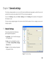
Chapter 7: General settings .......................... 101
7.1 General Settings ......................................................................101
7.2 Data Files Settings ..................................................................102
7.2.1 Data Files Filtering Methods ............................103
7.2.2 Managing Data Files Settings .........................104
7.3 Hex Viewer Settings ..............................................................106
7.4 Models Settings .......................................................................107
7.5 Report Settings ........................................................................108
7.5.1 Additional Report Fields.....................................108
7.5.2 Report Defaults ........................................................110
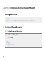
Appendix A: Using Python in the
Physical Analyzer ............................................ 112
1.1 Accessing the data store ....................................................112
1.2 File Systems, Files and Directories ................................112
1.2.1 Listing the current file systems ......................112
1.2.2 Get a specific file system by name ..............113
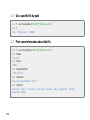
1.2.3 Go over all files in a file system
(recursively) ................................................................113
1.2.4 Get a specific file by path ..................................114
1.2.5 Print some information about the file .......114
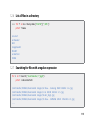
1.2.6 List all files in a directory ....................................115
1.2.7 Searching for files with a regular
expression ...................................................................115
1.2.8 Find out if a node is a file or a directory ...116
vii
1.2.9 Reading data from a file .....................................116
1.2.10 Viewing data in a textual hex dump ..........117
1.2.11 Creating a new file (without data) ...............118
1.2.12 Creating a new file from chunks ...................119
1.3 Memory Ranges ......................................................................120
1.3.1 Accessing the project’s Memory Ranges 120
1.3.2 Reading data from a Memory Range.........121
1.3.3 Creating a new MemoryRange and
adding to the project...........................................121
1.4 Models ...........................................................................................123
1.4.1 Accessing the Model Store ..............................123
1.4.2 Counting the amount of SMSes....................123
1.4.3 Print some details about an SMS ..................123
1.4.4 Print the SMS “Message” Field for all
SMSes.............................................................................124
1.4.5 Create a new SMS message .............................125
1.4.6 Using AddRange to add models quickly .126
1.4.7 Create a new Call ....................................................126
1.4.8 Create a new Contact ..........................................127
1.4.9 Create a new Email ................................................128
1.4.10 Create a new MMS Message ...........................129
1.4.11 Add an Attachment to an Email (or
MMS) ..............................................................................129
1.4.12 Create a new Location ........................................130
1.4.13 Create a new Journey ..........................................131
1.4.14 Create a new Instant Message .......................131
1.4.15 Create a new Chat .................................................132
1.4.16 Create a new Calendar Entry...........................133
1.4.17 Create a new Note .................................................133
1.4.18 Create a new Bluetooth Device.....................134
Chapter 1: Introduction
1.1 Overview
The UFED Physical Pro is comprised of two components:
The UFED hardware with Physical Extraction module, used to create Physical and/or Logical dumps from
mobile devices, which can then be saved to a USB disk drive, SD memory card, or directly to your PC.
The UFED Physical Analyzer (PA) PC application, which provides an in-depth physical memory analysis of the
extracted mobile phone data (phonebook contents, SMS messages, call logs, image files, video files, audio
files, and more) The Physical Analyzer also serves to generate comprehensive and verified evidence reports
of relevant data extracted and analyzed from the mobile device.
The UFED PA work flow consists of two steps:
Physical memory extraction via UFED hardware
Data analysis via PC Physical Analyzer
1.2 Physical Memory Extraction
The UFED’s physical memory extraction function provides the most comprehensive access to mobile device
data, including deleted and hidden information, as well as access to phone passwords. Unlike the logical
extraction process, the physical extraction bypasses the phone’s operating system, acquiring the data directly
as an image, from the phone’s internal flash memory.
1
The phone memory is captured into hex dump file (or files, depending on the memory structure of the specific
phone) which can later be analyzed and decoded using the UFED Physical Analyzer (PA) application.
1.3 Data Analysis
The UFED Physical Analyzer software allows the investigator to perform in-depth analysis of the extracted data
and generate reports.
The UFED PA application provides the following key features:
Analysis of the hex dump with a layered view of memory content
y Provides a detailed view of the hex dump
y Reconstructs the phone file system
y Decodes contact lists, SMS messages, call logs, phone information (IMSI, ICCID, user codes) and more
y Provides a view of data files – images, videos, etc.
y Provides access to both current and deleted data
y Retrieves phone passwords
Simple viewing and user friendly browsing of information
Powerful search tools
y Instantly search for project content
y Search the hex dump or file system
2
y Search by various parameters such as strings, bytes, numbers, dates
y Use GREP search (regular expressions) to look for specific data strings
y Bookmarking memory locations for indexing of key areas for later review
Ability to use Python shell commands for data analysis
Plug-ins
y Manage installed plug-ins
y Write your own plug-ins using Python scripting language
y Get additional plug-ins from the community website
Generation of customized reports
3
Chapter 2: Installation and Activation
2.1 Introduction
This chapter describes the activation process of the UFED Physical Extraction module on the UFED hardware
itself, as well as the installation and activation process of the UFED Physical Analyzer (PA) software on your PC.
2.2 Activating the UFED Physical Extraction Module
Important: This section applies to users upgrading their current UFED to the Physical Module. It is not
required for new UFED Physical Pro systems with the Physical Module already enabled.
The UFED has two types of licenses:
Logical license - Standard license for logical data extraction functionality.
Physical license - Advanced license enabling physical extraction and analysis.
To enable physical data extraction and analysis capabilities, the UFED Physical license must be activated.
NOTE: Activation of the UFED Physical Extraction Module must be performed on the UFED hardware prior to
installing the UFED Physical Analyzer software on your PC.
4
The installation of the UFED firmware on the UFED device is a two-step process and involves:
Upgrading the UFED software to a version that supports physical extraction.
Activation of the UFED Physical Extraction Module.
2.2.1 Renewing the UFED Physical Extraction Module License
To activate the UFED Physical Extraction Module, perform the following steps:
1.
Power on the UFED.
2.
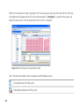
Locate the UFED device serial number and ID information by selecting Services > Software Versions from
the main menu. Make a note of the 7 digit serial number marked "S/N" and ID information.
Figure 1: The UFED Software Versions screen
5
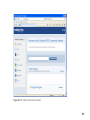
3.
On a PC with a web access, launch your web browser and go to my.cellebrite.com. You will be asked to
enter your user name and password to login into your MyCellebrite web page.
Figure 2: The Cellebrite UFED Activation screen
6
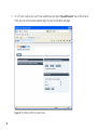
4.
In the Add a Device to My Devices section, enter the Serial number and Device ID of your UFED, which
were obtained from the Software Versions screen, then click Add Device.
Figure 3: Adding a new device
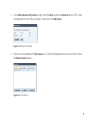
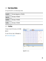
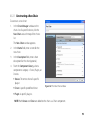
5.
The device will be added to the My Devices list. Click the checkbox beside this device, and then click on
the Renew License button.
Figure 4: My Devices list.
7
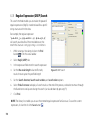
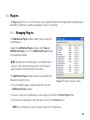
6.
On the Renewal Process page, fill in the required fields, including email address, then click the Send
Inquiry button. A quote for the required license will be sent to you via the specified email address.
Figure 5: The Renewal Process screen
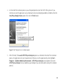
7.
8
After the license purchasing process is concluded, you will receive an email message containing the
activation key. To enter your key, power on your UFED System, select: Services > Upgrade > UFED License
> Activate License, and enter the key string.
2.2.2 UFED Software Upgrade
Once activated, the UFED Physical Extraction module is ready for use. To verify that you have the latest version
of the device firmware, you should upgrade the software version.
To upgrade the software version, select Services > Upgrade > Upgrade Application Now. For further
instructions, please refer to the UFED User Manual (chapter 11).
NOTE: If the menu options of the UFED Physical Analyzer do not appear, contact Cellebrite support to verify
that your UFED and UFED Physical Analyzer licenses are registered correctly.
2.3 Installing the UFED Physical Analyzer Application
2.3.1 System Requirements
PC
Windows compatible PC with a Pentium® IV or compatible processor running
at 1.6 GHz or higher
Operating System
Microsoft® Windows® XP with SP1 or later
Microsoft® Windows Vista™ or Windows 7
Memory
2 GB RAM
Space Requirements
500 MB of free disk space for installation
Additional Requirements
Microsoft® .Net version 3.5 Service Pack 1
9
2.3.2 Software Installation
Insert the UFED Physical Analyzer CD into your computer’s optical drive and browse the contents.
2.3.2.1 Installing the UFED Physical Analyzer
1.
Double click on the setup program to install the UFED Physical Analyzer application.
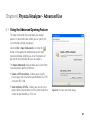
2.
Select the setup language, then click OK to continue.
Figure 6: The UFED Physical Analyzer setup wizard
3.
10
Follow the installation setup wizard prompts.
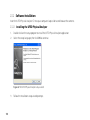
4.
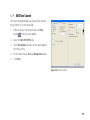
At the end of the installation process you will be prompted to install the HASP USB Kay drivers. If you
intend to activate the application using a hardware license key (dongle) provided by Cellebrite, check the
Install Hasp Dongle Drivers option, then click the Finish button.
Figure 7: HASP Dongle Drivers installation option
5.
When finished, if the Launch UFED Physical Analyzer option was checked at the end of the installation
process, the application will launch automatically. Otherwise, run the application by selecting Start >
Programs > Cellebrite Mobile Synchronization > UFED Physical Analyzer, or by double clicking the
UFED Physical Analyzer shortcut added to your desktop (if you selected to add it during the installation
process).
11
2.4 Activating the Physical Analyzer application
Activating the UFED Physical Analyzer can be done by:
Using an activation code
Using a hardware license key
To activate the application:
1.
Launch the UFED Physical Analyzer application.
2.
When launching for the first time, or when using a hardware
license key, a license window appears.
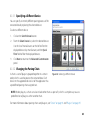
2.4.1 Using an Activation Code
A license is required to activate the UFED Physical Analyzer. The
UFED Physical Extraction module, which was previously activated,
can generate these licenses.
NOTE: The number of simultaneous activated copies of the
UFED Physical Analyzer application (one license per PC) is
restricted according to the purchased UFED Physical Extraction
module license.
12
Figure 8: The UFED Physical Analyzer
License window
2.4.1.1 Manual Activation Process
To manually enter the Activation Code:
1.
Note the Computer ID displayed in the UFED Physical Analyzer License window on your PC.
2.
On the UFED unit, select Services > Upgrade > PC License > Activate PC License > Manual Key Entry
from the main menu.
3.
Using the directional keypad, enter the Computer ID that was displayed in the UFED Physical Analyzer
License window. Select F3 to confirm.
4.
The UFED unit will display the PC Activation Code.
5.
On the Physical Analyzer License window, enter the Activation Code as it is displayed on your UFED unit.
6.
Click Activate.
Your UFED device and Physical Analyzer application are now both ready for use.
13
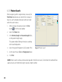
2.4.1.2 File Based Activation Process
Manual Key entry can be avoided by saving the key file to a USB drive. Doing so shortens the activation process
and can save a lot of time when installing multiple instances of the UFED Physical Analyzer.
On your PC:
1.
Connect a USB disk drive to your PC.
2.
Click the Write to USB button next to the Computer ID field to generate a Computer ID file which will be
written to your USB disk drive.
3.
On the Browse for Folder window, select the USB disk drive or target folder to which the Computer ID file
will be saved, and click OK.
NOTE: The Computer ID file can either be saved directly to a USB disk drive (if connected), or to any
location on your hard drive, in case you need to send it to a remote location for Activation Code
generation.
4.
Save the Computer ID file to the root directory of the USB disk drive.
5.
Safely disconnect the USB disk drive from the PC.
On your UFED unit:
14
1.
Connect the USB disk drive containing the saved ID file to any of the USB ports on the UFED unit.
2.
From the Main Menu on your UFED unit, select Services > Upgrade > PC License > Activate PC License >
Upload Key File to read the Computer ID from the USB disk drive.
3.
The UFED unit will display the generated PC Activation Code. Choose Save to USB to save the Activation
Code file to the connected USB disk drive.
4.
On the Physical Analyzer License window, click the Read from USB button next to the Activation Code
field.
5.
On the Browse for Folder window, select the USB disk drive or target folder to which the Activation Code
file was saved, and click OK. The Activation Code will load into the field.
6.
Click Activate.
Your UFED device and Physical Analyzer application are now both ready for use.
15
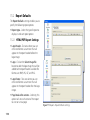
2.4.2 Using a Hardware License Key
You can also use a HASP hardware license key (dongle), provided by Cellebrite as part of your UFED system, to
activate the locally installed copy of UFED Physical Analyzer.
NOTE: Using a hardware license key provides you with a “mobile license”, enabling you to take your license on
the road and use it to activate a copy of the UFED Physical Analyzer application wherever you are.
To activate the UFED Physical Analyzer application using a hardware license key:
1.
Connect the hardware license key to a USB port on your computer.
NOTE: The HASP dongle drivers must be installed in order to use a hardware license key. If the drivers
were not installed during the software installation process, you can run the installation process again (see
“Installing the UFED Physical Analyzer” on page 10) and select the Install Hasp Dongle Drivers option at
the end of the process.
2.
After the key was recognized by the operating system, the application will be able to read the license and
allow you to continue.
Your UFED Physical Analyzer application is now ready for use.
16
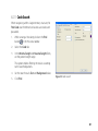
2.5 Deactivating a UFED Physical Analyzer License
In cases where a UFED Physical Analyzer installation, activated by an Activation Code, needs to be moved
to another PC, or cleanly installed on the same PC, you must first deactivate (remove the license) from the
computer. The license should be reloaded in your UFED device for re-use on a different PC or a clean install on
the same PC.
To deactivate the PC license, perform the following steps:
1.
Launch the UFED Physical Analyzer application.
2.
From the UFED Physical Analyzer menu, select Help > License > Deactivate.
3.
Click the Deactivate button to deactivate the PC license.
4.
A Browse for Folder window will appear. Select the target folder to save the deactivation key, then click
the OK button.
5.
The system will open a new window showing the deactivation key.
6.
On the UFED unit, select Services > Upgrade > PC License > Remove PC License from the main menu.
17
7.
Select either Manual Key Entry to enter the
license manually, or Upload Key File to upload it
from USB disk drive.
8.
If Manual Key Entry was selected, enter the
deactivation key using the directional keypad and
select F3.
9.
If Upload Key File was selected, connect the USB
disk drive to any of the UFED USB ports, then
press the X key to continue.
10. The deactivated license of the UFED Physical Analyzer application is now re-added to your UFED unit,
ready for use to activate another UFED Physical Analyzer installation.
18
Chapter 3: Performing Data Extraction
The information provided in this chapter is based on the assumption that the user is familiar with the basic
operations of the UFED device. Please refer to the UFED User Manual, Chapter 4 to familiarize yourself with UFED
before continuing. This chapter describes advanced features specific to the UFED Physical module only.
NOTE: Use the TS keys to move between options in the Main Menu. Use the W key to return to a previous
menu.
3.1 Performing a Physical Dump
When performing a physical dump operation, the UFED Physical Pro uses advanced extraction methods to
create a single hex dump file for each flash memory chip, or address range utilized by the mobile device.
Unlike conventional logical extraction processes, the physical extraction method bypasses the phone’s
operating system, acquiring the data directly from the phone’s internal flash memory. The phone memory
is captured into hex dump file(s) that will later be read and analyzed using the UFED Physical Analyzer
application.
The physical dump created includes memory space unallocated by the phone’s OS which may contain deleted
data such as SMS, Call logs, Phonebook entries, Pictures, Video and user passwords.
19
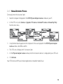
3.1.1 Using Removable Media
1.
Select Physical Dump from the Main Menu. Press OK or X to continue.
2.
Select the manufacturer of the phone from the Select Vendor menu. Press OK or
X to continue.
3.
Select the model of the phone. Press OK or X to continue.
4.
Select the target storage media (USB disk drive or SD Card) from the Select
Target menu. Press OK or X to continue.
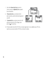
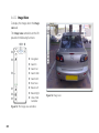
5.
You will be instructed to connect the source phone, using the appropriate cable
to the left USB port of the UFED, and then connect the target storage media to
the appropriate port right side of the UFED.
NOTE: USB disk drive storage media should be connected to right side Target
port. SD card storage media should be inserted in the SD card slot on the left
side of the UFED unit.
Make sure both are connected, and then press X to start the dump process.
NOTE: When connecting the phone to the UFED unit, some phone models
will prompt you to select the connection mode on the phone’s display screen.
Choose Data Mode, PC, or PC Sync mode. Actual selection choice will vary
depending on the phone model.
20
CAUTION: To prevent possible loss of data, do not disconnect the phone or storage media (USB disk
drive or SD card) during the extraction process.
6.
Upon the completion of the dump process, the UFED unit will display “Extraction
completed successfully”.
It is now safe to disconnect the phone and remove the target storage media for
analysis using the UFED Physical Analyzer PC tool.
7.
A folder named according to the phone model, current date, and a counter (for example, “Physical Nokia
GSM Generic 2009_05_15 (001)” is created on the target storage drive. This folder contains the extracted
binary files (one for each extracted memory module), and the UFD file, used by the UFED Physical
Analyzer application to access the extracted data.
Multiple dumps from different phones can be saved to the same USB drive or SD card. A new folder will
automatically be created for each device dump.
3.1.2 Extracting Data Directly to Your PC
1.
Connect your UFED device to your PC using a USB to mini-USB cable, utilizing the port marked “PC”
located on the top of your UFED unit. Your PC may prompt you to install drivers (refer to chapter 9 in the
UFED User Manual).
On the UFED unit:
1.
Select Physical Dump from the Main Menu. Press OK or X to continue.
2.
Select the manufacturer of the phone from the Select Vendor menu. Press OK or X to continue.
21
3.
Select the model of the phone. Press OK or X to continue.
4.
Select PC as the target. Press OK or X to continue.
On your PC:
5.
Launch the UFED Physical Analyzer application.
6.
In the application toolbar, click on the Read Data from UFED button.
7.
In the displayed UFED Downloader window, specify the download path to which
the dump should be saved, then click the Start button.
8.
The UFED unit will create the dump under the specified folder.
9.
At the end of the extraction process, you will be prompted to open the
extracted dump.
NOTE: Clicking the Open Target Folder button to display the content of the
selected target folder.
22
3.2 Extracting the File System
The File System Dump option extracts all the accessible files on the mobile phone using a logical process.
Extracting the file system is an alternative way to get data from phones, including phone models that are not
currently supported with physical dump. UFED Physical Pro provides access, and extracts hidden files and
databases inaccessible by other file system acquisition tools.
From the extracted file system you can get many different types of application files that can be decoded and
then searched for information, such as the Contacts or SMS database files.
The process for extracting a File System Dump is almost identical to performing a
Physical Dump, as described in “Performing a Physical Dump” on page 19.
Start by selecting File System Dump from the Main Menu, as in step 1 of “Performing a
Physical Dump” on page 19, and continue with same steps afterwards.
The resulting folder will include a ZIP archive of the phone’s file system, instead of the Hex file(s) of the
memory dump files, and a .ufd info file that enables the file system archive to be read by the Physical Analyzer
application.
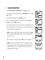
3.3 Extracting Passwords
The Extract Passwords feature provides quick access to the phone’s user passwords without the need to analyze
a dump using the UFED Physical Analyzer application.
1.
Select Extract Passwords from the Main Menu. Press OK or X to continue.
2.
Select the phone’s manufacturer from the Select Vendor menu. Press OK or X to continue.
23
3.
Select the phone’s model from the Select Model menu. Press OK or X to
continue.
4.
From the Select Target options, select USB Disk Drive or SD Card to store the
extracted data on the selected storage media, or select Display Only to display
the extracted password data on the UFED unit, without storing it.
5.
You will be instructed to connect the source phone, using the appropriate cable,
to the left USB port of the UFED unit marked “source”. Connect removable media
if extracting to file.
NOTE: USB disk drive storage media should be connected to right side “Target”
port. SD card storage media should be inserted in the SD card slot on the left
side of the UFED unit.
Make sure both are connected, and then press X to start the extraction.
NOTE: When connecting the phone to the UFED unit, some phone models
will prompt you to select the connection mode on the phone’s display screen.
Choose Data Mode, PC, or PC Sync mode. Actual selection choice will vary
depending on the phone model.
6.
24
When the extraction process is completed, the password information will be displayed on the screen.
When the phone has more than one password, multiple passwords will be shown.
Chapter 4: Overview of UFED Physical Analyzer Application
4.1 Introduction
The UFED Physical Analyzer application provides powerful analysis tools for the extracted phone data, and
simplifies the task of navigating through the phone’s data structures. Using the UFED Physical Analyzer
application will assist you in the complex tasks of intelligence gathering, investigative research, and providing
legal evidence in the form of reports.
The application is designed to utilize the memory extracted by the UFED unit and presents the phone’s hex
dump, file system and analyzed data in a clear and concise way, allowing investigator to use powerful search
tools to parse and decode relevant information.
As a completing step, the application will allow you to generate reports of your findings and export them in
various file formats, such as HTML, PDF, Excel (*.xlsx), and XML.
4.2 Launching UFED Physical Analyzer Application
To launch the UFED Physical Analyzer application, double click on the UFED Physical Analyzer desktop
shortcut icon, or select Start > Programs > Cellebrite Mobile Synchronization > UFED Physical Analyzer.
25
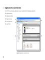
4.3 Application Structure Overview
The UFED Physical Analyzer application structure is comprised of the following components:
1 Application Menu
2 Application Toolbar
3 Project Tree Area
1
4 Data Display Area
2
5
5 Search Field
4
3
Figure 9: Application structure overview
26
4.3.1 Application Menu
The application menu provides access to the following menus and commands and functions:
File menu:
y Open: Select and open a file for analysis using the standard analysis process.
y Open (Advanced): Select and open a file for analysis using the advanced analysis process. See “Using the
Advanced Opening Feature” on page 61.
y Recent: Displays a list of the recent projects.
y Close: Closes the currently active project.
y Exit: Closes the application and all active projects.
View menu:
y Show Welcome Screen: Displays the Welcome screen. See “The Welcome tab” on page 42.
y Trace Window: Show/hide the trace panel at the bottom of the data display area.
Tools menu:
y Dump File System: Exports and saves the parsed file system to actual files and folders in a directory
structure. See “Exporting the File System” on page 100.
y Read Data from UFED: Extract phone data directly to the computer.
y Dump GPS / Mass Storage Device: Reads and saves data from GPS and mass storage devices connected
to the workstation via USB connection.
27
y Settings: Access to the application settings window. See “General settings” on page 101.
Python menu:
y Python Shell: Opens the Python Shell window for user customized analysis using Python commands. See
“Using the Python Shell” on page 100.
y Run Script: Runs a pre-written Python script (*.py file).
y Run Script (Debug enabled): Enables you to run a pre-written Python script (*.py file) in debug mode.
Plug-ins menu:
y Add/Remove Plug-ins: Displays the list of installed plug-ins to enable management of the currently
installed plug-ins. See “Managing Plug-ins” on page 97.
y Run Plug-in: Allows the user to select a specific plug-in and run it. See “Running a Specific Plug-in” on
page 98.
y Chain Manager: Displays the Chain Manager window to enable management and creation of device
processing chains. See “Managing Chains” on page 91.
Report menu:
y Generate Report: Generates a report summary of all information found by the analysis process. See
“Generating Reports” on page 57.
Help menu:
y Manual: Launches Adobe Reader (aka Acrobat Reader) and displays the user manual (in PDF format).
y License sub-menu:
28
y Enter New License: Enables you to enter a new Activation Code.
y Show License Details: Displays the current license code validation period, and the current Computer ID
and Activation Code.
y Show Dongle Details: When using a hardware license key, displays the details of the currently used
dongle.
y Deactivate: Deactivates the license used to activate the application on the current workstation. See
“Deactivating a UFED Physical Analyzer License” on page 17.
y About: Provides information about the installed UFED Physical Analyzer application version and its
components.
29
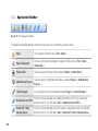
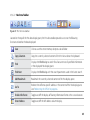
4.3.2 Application Toolbar
Figure 10: The Application Toolbar
The application toolbar provides shortcuts to quickly access commonly used functions:
30
Open
Click to open a file for analysis (File > Open...).
Open (Advanced)
Click to use the advanced options to open a file for analysis (File > Open
(Advanced)...).
Python Shell
Click to display the Python Shell window (Python > Python Shell...)
Add/Remove Plug-ins
Click to display the Add/Remove Plugins window (Plug-ins > Add/Remove
Plug-ins...)
Chain Manager
Click to display the Chain Manager window (Plug-ins > Chain Manager...)
Read Data from UFED
Initiates an extraction process of phone data from a UFED unit connected
directly to the PC via USB cable (Tools > Read Data from UFED...).
Dump GPS / Mass
Storage Device
Initiates an extraction process of GPS or mass storage device data connected
directly to the PC via USB cable (Tools > Dump GPS / Mass Storage Device...).
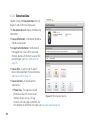
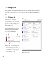
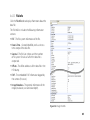
4.3.3 Project Tree Area
The Project Tree area displays the following extracted information structure of each
file opened for analysis:
Extraction data
Device info
Images (one for each extracted memory module or extracted memory range)
Memory ranges
File systems
Analyzed data (where supported)
Data files
Tags
Reports
By opening the Analyzed data or Data files sub-trees, you can drill down into
the tree structure to search for specific information. Double clicking on any of the
lower-level nodes, will display the relevant information viewer in the Data Display
area.
Figure 11: Project Tree
Overview
Each extraction file you open will add a project at the bottom of the Project Tree.
Every branch in the Project Tree can be expanded or collapsed by clicking the or icons. In addition, the
or
buttons at the top the tree section.
entire tree can be fully expanded or collapsed by clicking the
31
4.3.3.1 Extraction Data
Double clicking the Extraction data item will
display its tab in the Data Display area.
The Extraction data tab displays the following
information:
Device Information - Information related to
the device extraction.
Image Hash Information - Verification of
the logged hash values of the extracted
memory dump with the hash values of the
parsed images. See “Hash Verification” on
page 70.
Device Info - A Summary of th specific
device info pulled from the extracted data.
See “Device Info” on page 34.
Device Content - Analyzed content,
separted to:
y Phone Data - The types of analyzed
phone data found in the extracted
Figure 12: The Extraction Data tab
memory dump, such as Call Log,
Contacts, SMS Messages, and others. For
the complete list of Phone Data types, see “Analyzed Data” on page 38.
32
y Data Files - The types of standard data files found in the extracted memory dump, such as Images, Video,
Audio, and Text files.
NOTE: The Extraction data tab will be displayed automatically whenever you open a new file for analysis.
Clicking on any of the Device Content categories will display the relevant information viewer tab in the in the
data display area, listing all the items logged in this category. See “Analyzed Data” on page 38 and “Data Files” on
page 40.
Clicking the Generate Report button at the top right of the tab will prompt you to generate a report for the
current project. See “Generating Reports” on page 57.
33
4.3.3.2 Device Info
Double clicking the Device info item will
display its tab in the data display area.
The Device info tab provides extensive
amount of existing and deleted information,
as well as important identifiers of the phone
such as, SIM card and user lock codes, where
supported.
The Properties list is divided to display the
different Device Info categories.
NOTE: The number of categories and
amount of displayed information may
vary, depending on the device model and
manufacturer.
Figure 13: Device Info
A checkbox next to each of the categories
and properties indicate whether this item will be included (checked) or excluded (unchecked) in the report.
A Find field, at the top of the properties list allows you to filter the displayed items (Categories, Subjects, and
data) to display items containing the entered text string.
34
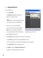
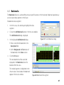
4.3.3.3 Images
The Images item of the project tree lists all the dump files generated by the data extraction from the memory
modules of the device.
Figure 14: Memory dump images
Double clicking on any image item will
display it in a new Hex View tab for it in the
data display area.
Figure 15: Hex View tab
35
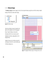
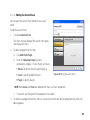
4.3.3.4 Memory Ranges
The Memory ranges item of the project tree lists the analyzed memory ranges for each of the memory module
dumps of the device (listed under Images).
Figure 16: Memory ranges
Selecting a memory range will automatically
add it to the highlights list of the displayed
binary image it belongs to (located at
the bottom of the Hex view tab), and will
highlight the memory range portion in the
displayed data.
Double clicking on any memory range item
will display its content in a new Hex View tab
in the data display area.
Figure 17: Highlighted memory range in the image Hex view tab
36
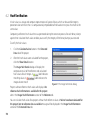
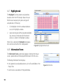
4.3.3.5 File Systems
The File systems item of the project tree lists all the file systems found
and reconstructed out of the analyzed binary data.
Each file system found will appear as a hard drive icon
.
You can browse the file system to display folders and files by clicking the
or icons.
NOTE: Deleted items appear as
.
Double clicking on any file item in the file system tree will display its
content in a new Hex View tab in the data display area.
Selecting a file system item will automatically add it to the highlights
list of the displayed binary image and/or memory range it belongs to
(located at the bottom of the Hex view tab), and will highlight its data
range portion in the displayed data.
Figure 18: File systems
37
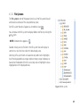
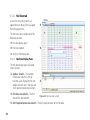
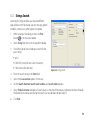
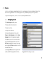
4.3.3.6 Analyzed Data
This Analyzed data item of the project tree displays phone data item
groups that were found in the extracted data.
The listed of items will include:
Personal information, such as calendar, contacts, notes, call log
Messaging items, such as SMS, MMS, email, instant message, chat
Web browser items, such as bookmarks, history, cookies
GPS information, such as locations, journeys, fixes
Device information, such as bluetooth pairings, SIM data
Figure 19: Analyzed Data section
NOTE: Additional types of Analyzed Data groups may be available
according to the device features and the application version.
A number, in parenthesis, next to each item type, shows the number of items of this type that were found in
the extracted data (excluding duplicates).
Expanding any of the Analyzed Data item groups by clicking the icon next to it, will reveal a 2nd level sorting
of the logged items according to type or folder. Clicking icon will collapse the 2nd level sorting. For example,
SMS Messages will be sorted according to the sorting folders used by the messaging feature of the phone, such
as: Drafts, Inbox, Outbox, Sent, etc.
38
Double clicking on each of the item type groups or 2nd level sorting group, will display a detailed table of all its
items in the data display area. The structure and information displayed by the table will vary according to the
selected item type.
Selecting any analyzed data category
will automatically add it to the
highlights list of the displayed binary
image and/or memory range it belongs
to (located at the bottom of the Hex
view tab), and will highlight its data
range portions in the displayed data.
Figure 20: Analyzed Data display tables
39
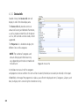
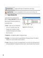
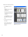
4.3.3.7 Data Files
This Data files item of the project tree provides access to the files that
were found in the extracted data, filtered according to the following file
types:
Images - Files that were recognized as image file formats
Videos - Files that were recognized as video file formats
Audio - Files that were recognized as audio file formats
Text - Files that were recognized as text file formats
NOTE: Deleted items appear as
.
Note: New Data File groups for other common file types, can be created
according to the Data Files setting. See “Data Files Settings” on page 102.
Double clicking on each of the filtering groups will display a list of the
parsed items in the data display area. In addition, the tree view can be
expanded to allow access to individual files. See “Working with Data Files”
on page 82.
Figure 21: Data Files section
40
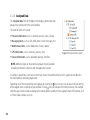
4.3.3.8 Tags
When the extracted data is processed, certain file types are identified and
are tagged accordingly.
NOTE: The four default tags are Image, Text, Audio, and Video, and files
that were identified and tagged by each of them will also show up
under the Data files section.
You can use plug-ins or the Python shell to look for additional data
segments and tag them with one of the existing tags, or log them under a
new branch in the Tags section by applying a custom tag to them.
NOTE: Deleted items appear as
.
Double clicking a tagged item will take you to its file item under the File
systems item.
4.3.3.9 Reports
Double clicking a report item listed under Reports will display the report
file generated for the project using the application associated with the
report format (ie. Internet Explorer for HTML report).
If a report has not yet been generated for this project, the Generate
Report dialog will be displayed prompting you to generate one.
Figure 22: Tags section
41
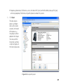
4.3.4 Data Display Area
Displays the content of the currently selected project tree item. A new data display panel is opened for each
selected item (ex. Hex memory, list of contacts, file content, etc.). Tabs are utilized to navigate between the
views.
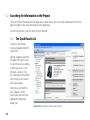
4.3.4.1 The Welcome tab
The Welcome tab is automatically
displayed in the data display area when the
application is launched, and displays a list of
the recently opened files.
Each recently opened file item in the list is
displayed as a framed information group
that contains the following items:
1
2
3
5
4
6
1 Device icon - A thumbnail image of the
device from the application resources, if
available. When not available a general
placeholder image is used.
42
Figure 23: Welcome screen
2 File Name - The name of the opened file, without the file extension.
3 File Path - The file system path to the file location.
4 Device Model - The identified device manufacturer and model, or BINARY in case the opened file was a
binary dump.
5 Date and time - The date and time stamp in which the file was opened.
6 Browse link - A direct link to the file in file system.
Click on a framed item to open the recently opened files for analysis.
Click on the Browse... link of a recent file item to go directly to the file associated with it in the file system.
NOTE: Whenever the Welcome tab is not displayed, you can display it by selecting View > Show Welcome
Screen.
43
4.3.4.2 Hex View tab
A new Hex View tab (screen) will
appear for each binary item you open
from the project tree.
2
4
The Hex View tab is comprised of the
following sections:
5
1 Hex data display pane
2 Hex View toolbar
1
3 Analysis Information tabs
4.3.4.2.1 Hex Data Display Pane
The Hex data display pane is divided
into 3 sections:
4 Address Column - The number
information column in Hex or
Decimal value, displaying the start
address of each row in the Hex and
ASCII representation data sections.
3
5 Hex data view column - The Hex
data of the selected item.
Figure 24: Hex View tab (screen)
6 ASCII representation view column - The ASCII representation of the Hex data.
44
6
4.3.4.2.2 Hex Data Toolbar
Figure 25: The Hex View toolbar
Located at the top of the Hex data display pane, the Hex data toolbar provides access to the following
functions related to the data displayed.
Save
Click to save the entire memory dump to a local folder.
Copy Selection
Copy the currently selected content of the Hex View tab to the clipboard.
Find
Displays the Find dialog to search for all occurrences of specified information
in the displayed Hex display pane.
Find Next
Displays the Find dialog with the search parameters used in the latest search.
Add Bookmark
Bookmark the currently selected content of the Hex display pane.
Go To
Redirect the offset to specific address in the content of the Hex display pane.
See “Redirecting the Offset” on page 86.
Enable Info Frame
Toggles on/off the display of floating information frame at the cursor location.
Show Address
Toggles on/off the left address column display.
45
Show ASCII view
Toggles on/off the right ASCII representation column display.
Locate File in Tree
Selects the displayed file in the File Systems section of the Project Tree.
4.3.4.2.3 Analysis Information Tabs
Located under the Hex Data display pane by
default, the Analysis Information tabs displays the
following types of information related directly to
the displayed Hex data:
1 Values - A wide array of value interpretations,
such as 8, 16, 32 and 64 bit, various String
encoding, Date & Time formats, and more,
calculated on the fly for the currently selected
data in the Hex view.
1
2
3
4
Figure 26: Analysis Information tabs
2 Bookmarks - A list of bookmarks added in the displayed Hex data.
3 Highlights - A list of content segments markups highlighted in the displayed Hex data. The number of
highlight results is shown in brackets next to the tab name.
4 Search - Displays results of a search in the displayed Hex data. A new search results tab will open for each
search query performed. The number of results for each search is shown in brackets next to the tab name.
46
4.3.4.2.4 Rearranging the Analysis Information Tabs
You can rearrange the display of the Analysis Information to suit your preference:
Double click the header strip of the section to display the entire section as a floating panel. Double click the
floating panel header strip to dock it back to the default location (at the bottom of the Hex View tab).
Double click the name label of any tab to display it as a floating panel. Double click the floating panel header
strip to dock it back to the original location.
Drag the name label or floating panel over any of the docking labels that appear to dock it at that location in
the Hex View tab.
4.3.4.3 Data Items View tab
A Data Item View tab will be added to the
data display area whenever you double click
on a data item group located under the
Analyzed Data or Data Files sections of the
project tree.
The Data Item View tab displays a list of all
the files of a specific type (images, videos,
audio, or text) that where found during the
data analysis process.
Figure 27: Files View tab
NOTE: Image files can be displayed either
in Table view or Thumbnail view, using the
two display option tabs at the top of the files list display pane.
47
Chapter 5: Physical Analyzer - Basic Use
5.1 Opening File for Analysis
1.
If the phone data was extracted to a removable media, connect the USB disk drive or SD card containing
the extracted data to a PC with an activated running copy of UFED Physical Analyzer application.
NOTE: For faster processing, copy the extracted data folder from the removable media to the PC, and
open directly from the PC.
2.
From the application menu, select File > Open, or click the Open button on the application toolbar.
3.
Navigate to the location of the extracted phone data folder, and open it.
4.
In the displayed Open dialog, select the data extraction file.
By default, the Open dialog is set to display UFED Dump files (*.ufd) which is the information mapping file
of the extracted phone data.
Additional formats available for selection from the Files of Type list of the Open dialog include:
UFED report (*.xml). Logical reports generated by the UFED unit.
Binary files (*.bin). Raw binary files or any hex dump generated by another application.
NOTE: Opening a binary file will only allow hex dump view, with no file system or data analysis.
However, you will still be able to perform your own searches and analysis using the provided tools.
48
Proprietary phone data. File formats such as the Nokia PM (*.pm) and the BlackBerry backup file (*.ipd),
which are proprietary file formats of specific phones/vendors file systems.
5.
Click Open.
The data analysis
process will begin
and run for several
seconds. At the end
of the process, a
new project will be
added in the Project
Tree area, and the
Extraction Summary
screen will display in
the Data Display area.
Figure 28: New opened project
49
5.2 Searching for Information in the Project
The search field at the top right of the application window allows you to search for information in the entire
project or projects that are currently open in the application.
To search for contents, type the search string in the field.
5.2.1 The Quick Results List
A quick list of matching
results will appear under the
search field.
Sorting categories along the
left edge of the quick results
list, sort the results according
to their type (such as SMS
Messages, Contacts, Files,
etc.), and display the number
of matching results found in
each type category.
Selecting a result from the
list will display it in the
Data Display area using the
appropriate information
display tab.
50
Figure 29: The contents search quick results list
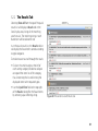
5.2.2 The Results Tab
Selecting Show All from the top of the quick
results list will display a Results tab in the
Data Display area, listing all the matching
search results. The matching string in each
found item will be colored in red.
As in the quick results list, the Results tab list
will display the found items sorted according
to type categories.
To make it easier to scroll through the results:
Click on the small triangle at the left of
each sorting category header to collapse
or expand the items list of the category,
thus shortening the list and limiting the
displayed items to the required types.
Use the Quick Filter field at the top right
of the Results tab to filter the found items
by entering a quick filtering string.
Figure 30: The contents search Results tab
51
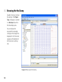
5.3 Browsing the Hex Dump
Double clicking on a binary
hex dump in the Project
Tree will display its content
in a Hex View tab within
the data display area.
You can display the
extracted Hex dump by
clicking on the image links
displayed in the Extraction
Log area at the bottom of
the Extraction Summary
tab.
Figure 31: Browsing the Hex dump
52
5.4 Browsing the File System
The UFED Physical Analyzer has the
ability to reconstruct and display the
phone file system as a tree structure
of folders and files.
To browse the file system:
1.
Click the icon at every node to
expand the tree display under it.
2.
Continue drilling down in the
file system tree to explore its
content.
3.
When you reach a file:
4.
Double click on it to display its
information in the data display
area.
The number information tabs
Figure 32: File Hex dump display (after double clicking on the file)
displayed for the file will change
according to the file type. For
example, an unknown file may
display only the Hex View and File info tabs, while a jpeg image may display additional Image view and
Meta data tabs. The default view is the Hex view.
53
While the Hex dump of an image is displayed in the Data Display area, selecting a file under the file system tree
will highlight the data portion of this file in the Hex dump data. The Highlights list, under the Hex viewer, will
display the data chunks in the Hex dump from which this file is comprised.
Figure 33: File data display in the extracted Hex dump
Files in the reconstructed file system will display one of the following icons:
Existing file found in the file system
Deleted file data found in the file system
54
5.5 Browsing the Analyzed Data
The Analyzed Data and Data Files sections of the project tree display data items that were found in the
extracted device data during the analysis process.
The difference between item types grouped under Analyzed Data to those grouped under Data Files is that
Analyzed Data item types are related to phone specific features such as Contacts, SMS Messages, Call Logs, and
other, while Data Files item types are data and media files in common or known file formats, used by devices
and computers, such as image, video, audio, or text files.
5.5.1 Analyzed Data
Double clicking on an Analyzed Data group, will add a data list tab to the Data Display area, listing all items of
this type found in the extracted data.
The structure and content displayed by the list table will vary according to the selected item type:
For the complete list of Analyzed Data item types, see “Analyzed Data” on page 38.
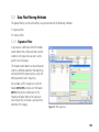
5.5.2 Data Files
Data files are image, video, audio or text files. Additional data files groups will display according to the Data Files
settings. See “Data Files Settings” on page 102.
Double clicking on any data files group will display the list of the data file items (images, videos, etc.) that were
found in the extracted data.
55
For each of the data file types, the table list includes the following fields:
Checkbox
Indicates whether to include (checked) or exclude (unchecked) the item in the report
generated.
Del?
An icon indicating if the data file was deleted (red “x” ), not deleted (green dot ), or has
an unknown status (gray dot ).
Image
A thumbnail of the image or an icon of the file type.
Name
The file name.
Path
The root path of the data file.
Size
The size of file.
Metadata
Additional metadata of the data file.
Created
The creation time stamp of the data file.
Modified
The modification time stamp of the data file.
Accessed
The last access time stamp of the data file.
NOTE: Image files can be displayed either in Table view or Thumbnail view, using the two display option
tabs at the top of the files list display pane.
Double clicking on an item record (table row) will add a Hex Viewer tab with the Hex data of the selected file to
the Data Display area.
56
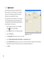
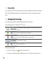
5.6 Generating Reports
You can generate a summary report of all information found in the physical dump by:
Selecting Report > Generate Report from the application menu.
Clicking the Generate Report button in the top right corner of the Welcome tab.
If a report was not
previously generated,
double clicking on
Reports section in the
Project Tree.
Using any of these
methods will display the
Generate Report dialog,
where you are prompted
to provide the following
information:
Report For Project - A
list of the currently
opened projects. Select
the project for which
the report will be
generated.
Figure 34: The Generate Report dialog
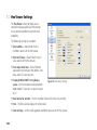
57
Report Type - The file format of the generated report. Select from: HTML, MS Excel spreadsheet (.xlsx), or
XML.
Report Data:
y Report Dataset - The Analyzed Data and Data Files section that will be included in the report. Only
checked data types will be included in the generated report.
y Additional Fields - Additional useful information fields added by the user in the Additional Report Fields
settings. See “Additional Report Fields” on page 108.
Case/File number, Examiner name, Department, Location, and Notes, are 5 additional default fields, from
which, the Case/File number and Examiner name are set as required fields. You can edit these fields and
change their attributes in the report settings. See “Additional Report Fields” on page 108.
Click on the Settings button to jump directly into the Additional Report Fields settings to edit existing
fields or add more fields. The changes and new fields will be automatically applied to the open Generate
Report dialog when you click Apply or click OK and return to the Generate Report dialog.
Use the Reset button to clear all the information entered in the fields, and set them back to their default
values.
Report Settings - The logo header, Image, and footer, sections page breaks, PDF generation, and item totals
display settings of the report.
The default contents and options of these settings are set by the Report Defaults setting of the application.
See “Report Defaults” on page 110.
58
Click on the Settings button to jump directly into the Report Defaults settings to edit the contents and
options. The changes will be automatically applied to the open Generate Report dialog when you click
Apply or click OK and return to the Generate Report dialog.
Use the Reset button to clear all changes made, and set the contents and options back to their default
values.
button to
Save to - The path and folder name to which the generated report file will be saved. Click the
set a different path. The default target folder name will be constructed from the project name and the date
and time it was generated (for example, Samsung GSM_SGH-E790.2011-01-18.12-19-84).
Click Generate to generate the new report.
Note: The Generate button will not be enabled until all the required fields are filled.
When the report generation ends successfully, you will be prompted to open the generated report file. The file
will be opened using the associated application to the file format installed in the workstation.
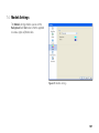
Once a report has been generated for the project, it can be accessed from the Reports section in the project
tree. Double clicking on any of the generated reports will open it in the associated application installed in the
workstation. Right clicking any of the generated reports will allow you to open the report file or select Open
containing folder to browse the files and folders of the report.
59
Figure 35: Typical HTML, Excel, and XML reports
60
Chapter 6: Physical Analyzer - Advanced Use
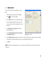
6.1 Using the Advanced Opening Feature
The Open (Advanced) feature enables you to open
projects in advanced mode, where you can specify the
system dumps and parsing options.
Selecting File > Open (Advanced) or clicking the
button in the application toolbar displays the Open
(Advanced) dialog, enabling you to set the process of
parsing the extracted data for your new project.
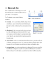
The Open (Advanced) dialog enables you to select from
two main project opening methods:
Select a UFED extraction - Enables you to specify
how to parse the extracted or specified data of a UFED
extraction file (*.ufd).
Start without a UFD file - Enables you to start a new
project from extracted data or a file system dump that
where not generated by a UFED unit.
Figure 36: The Open (Advanced) dialog
61
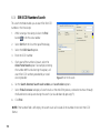
6.1.1 Advanced Opening of a UFED Extraction File
The standard Open process uses a parsing process set according to the device and manufacturer information
logged in the *.ufd file, or known file formats (*.bin, *.pm, *.ipd, etc.), to parse the data and create a new project.
Using the Select a UFED extraction method enables you to skip the standard Open process, and specify a
custom parsing process, or specify how to parse unknown devices.
To create a new project from UFED extracted data using Open (Advanced):
1.
Click the Select a UFED extraction button.
2.
In the displayed file selection dialog, select the *.ufd
file that will be processed and click OK.
The dialog contents changes to Advanced
Customization and displays the following settings:
Device - The manufacturer name and model of
the device.
Selected Chain - The standard device parsing
chain automatically assigned to the device.
Binary Dumps - The binary dumps images
referenced by the UFD file.
62
3.
Customize the file open options as described in
sections 6.1.1.1 to 6.1.1.4.
4.
Click Finish.
Figure 37: Advanced opening of a UFED extraction
6.1.1.1 Specifying a Different Device
You can specify an entirely different parsing process of the
extracted data by replacing the selected device.
To select a different device:
1.
Click on the Switch Device button.
2.
From the Select Device list, select the desired device.
Use the list of manufacturers on the left to filter the
displayed devices by manufacturer, and the Quick
Filter field to filter the displayed devices.
3.
Click Next to return to the Advanced Customization
panel.
6.1.1.2 Changing the Parsing Chain
A chain is a set of plug-ins grouped together in a certain
order, which is used to process the extracted data. Each
device in the supported devices list of the application has
a predefined parsing chain assigned to it.
Figure 38: Selecting a different device
NOTE: Beside plug-ins, a chain can also include other chains as part of it, which is a simpler way to use a
predefined set of plug-ins within another chain.
For more information about parsing chains and plug-ins, see “Chains” on page 91 and “Plug-ins” on page 97.
63
6.1.1.2.1 Selecting a Different Chain
To select a different chain:
1.
Click on Switch Chain.
The Switch Chain dialog opens and displays the
default chain assigned to the device.
NOTE: A device can have several assigned chains, but
only one of them can be set as the default chain.
2.
From the chains list, select the desired chain.
Select the manufacturer name under the Current
Device section at the top of the list to display the
chains assigned to devices of the same manufacturer.
Figure 39: Selecting a different chain
Under the Chains section of the list:
Select My Chains to select from the list of custom chins you constructed.
Select All Chains to select from the list of all predefined device chains.
Use the list of manufacturers on the left to filter the displayed devices by manufacturer.
Use the Quick Filter field to filter the displayed list items.
3.
Click Select to return to the Advanced Customization panel.
The default chain will be replaced by the selected chain.
64
6.1.1.2.2 Editing the Current Chain
You can open the current chain and edit it to suit your
needs.
To edit the current chain:
1.
Click on Customize Chain.
The chain structure dialog of the current chain opens
and displays the chain.
2.
To add a component to the chain:
A.
Click Add Chain/Plugin.
B.
From the Component Library, select a
components category - Chains, Plugins, or Devices.
Device: The entire chain of a specific plug-in.
Chain: A specific predefined chain.
Figure 40: Editing the current chain
Plugin: A specific plug-ins.
NOTE: Both Device and Chain are added to the chain as a Chain component.
C.
3.
Click on the + at the right of the component line to add it.
To remove a component from the chain list, click on the × at the right of the component item, then click
Yes to approve.
65
4.
Click OK to return to the Advanced Customization panel.
The current chain will be replaced by the customized chain.
6.1.1.2.3 Saving a Customized Chain
After you customize a chain, you can save the changes made to the chain for future use using the Save As or
Save buttons added under the Selected Chain section.
NOTE: the Save button is enabled only for customization done for unlocked user defined chains saved in My
Chains. For more information about user defined chains, see “Managing Chains” on page 91.
To save a customized chain:
1.
Click Save (if enabled) to replace the user defined chain with the current one or Save As to save the
current chain as a new chain.
2.
If you click Save As, enter a name for the new chain and click Save.
The new chain will be added to the My Chains list of customized chains of the application, and the saved
chain will appear as the Selected Chain.
6.1.1.3 Add a Binary Dump
You can add more binary dump files received from a different source or generated separately to the project.
To add a binary dump, click on Add Binary Bump and select the binary dump file you wish to add. Each binary
dump you add will show up as a separate binary dump component in the Binary Dumps section of the dialog.
To remove a binary dump, click on the
66
icon that appears at its top right corner when rolling over it.
6.1.1.4 Add a File System Dump
You can add a file system dump to the project received either as a ZIP archive or as a folder containing the file
system dump files.
To add a file system dump, click on either the Zip File or Folder buttons and select the ZIP archive or folder you
wish to add.
NOTE: You can add one file system dump. Trying to add more than one will remove the previously added file
system dump, regardless if it’s a zip archive or folder.
To remove a file system dump, click on the
icon that appears at its top right corner when rolling over it.
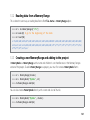
6.1.2 Advanced Opening of a non-UFED Extraction File
When you receive binary and file system dumps that were not generated by a UFED unit, or you don’t have the
*.ufd file that accompanies them, you can use the Open (Advanced) feature to define how to parse them for
the new project.
The Start without a UFD file option provides you with two starting points for your new project:
Select Device - Enables you to select the specific device definition that will be used to parse the extracted or
specified data. This option is useful when the device manufacturer and model are known to you.
Blank Project - Provides you with an empty Advanced Customization panel to set your process parameters
and data. This option is useful when you have no information about the device and/or manufacturer, and
would like to construct a custom parsing process.
67
6.1.2.1 Starting with Device Selection
To create a new project for an extracted data, based on a known device:
1.
Click the Select Device button.
2.
From the Select Device list, select the desired device.
Use the list of manufacturers on the left to filter the displayed devices by manufacturer, and the Quick
Filter field to filter the displayed devices.
3.
Click Next.
The Advanced Customization panel will display with the name and default parsing chain of the selected
device.
4.
To select a different device, see “Specifying a Different Device” on page 63.
5.
To select a different parsing chain, see “Selecting a Different Chain” on page 64.
6.
To customize the parsing chain, see “Editing the Current Chain” on page 65.
7.
To add binary dumps, see “Add a Binary Dump” on page 66.
8.
To add a file system dump, see “Add a File System Dump” on page 67.
9.
Click Finish.
6.1.2.2 Starting from a Blank Project
68
1.
Click the Blank Project button.
2.
To select a device, see “Specifying a Different Device” on page 63.
3.
To select a different parsing chain, see “Selecting a Different Chain” on page 64.
4.
To customize the parsing chain, see “Editing the Current Chain” on page 65.
5.
To add binary dumps, see “Add a Binary Dump” on page 66.
6.
To add a file system dump, see “Add a File System Dump” on page 67.
7.
Click Finish.
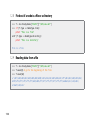
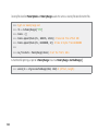
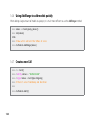
6.1.3 Saving a UFD File
At any point of setting the Open (Advanced) parameters you can click the Save UFD button at the top right
corner of the dialog to save a *.ufd file that logs the selected binary dumps and device information, for future
use.
The next time you need to parse that file you can use the saved UFD file to open it with Open or Open
(Advanced).
69
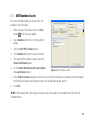
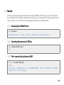
6.2 Hash Verification
A hash value is a unique and compact representation of a piece of data, which can be used for integrity
protection due to the fact that it is computationally improbable to find two distinct inputs that hash to the
same value.
Comparing a reference hash value that was generated during the extraction process for each binary dump
against their calculated hash values enables you to verify the integrity of the binary dumps you received.
To verify the hash values:
1.
Click the Calculate hashes button in the Extracted
Data tab of the project.
2.
After the hash values were calculated for the project,
click the Show Details button.
The Image Hash Details dialog will display the
comparison result of the reference and calculated
label indicates
hash values of each image. A
label indicates the
matching values. A
images do not match.
Figure 41: The Image Hash Details dialog
Projects without reference hash values will display a No
reference hash information is available for this project
alert in the Image Hash Information section of the Welcome tab.
You can calculate hash values for a project without hash reference values. A Hashes have been calculated for
this project, but no reference data is available message will be displayed in the Image Hash Information
section of the Extracted Data tab.
70
6.3 Searching for Information in the Hex Dump and Parsed Data
6.3.1 Search Modes
The following search modes enable you to search for
information within the Hex dump:
Find - Enables searching for specific parameters such as
strings, bytes, dates and more.
RegEx (GREP) - Enables searching for strings using
Regular Expressions.
SMS 7Bit (PDU) - Enables searching after SMS text
strings.
Pattern - Enables searching for text patterns, in cases in
which the pattern of the text is understood but not the
text itself (mainly used for 7 bit search to locate SMS
messages).
Figure 42: Find dialog modes
Code - Specialized search tool used to find user codes and passwords.
NOTE: The Find modes were built using the Plug-ins architecture. The following find options can be enhanced
and extended by adding new search plug-ins developed either by Cellebrite or by the user.
71
6.3.2 Search Results
If the Find All Instances option was selected
for the search, the results will appear in the
Search results tab at the analysis information
section (under the Hex view pane).
To make it easier to distinguish between
the given results of each search performed,
different Text and Background colors can be
set for each search you run.
Search results include the following fields:
Figure 43: Typical String search results
#
The number of results.
Offset
The address offset of the data file in the HEX dump.
Length
The string length in bytes.
Value
The string itself.
Comment The file name/number and the location of the result in the Hex dump. When empty, the found
data is in the un-allocated area.
Clicking on any of the search results will display the item in the Hex view.
The Find field above the results list filters the search results by searching for specific data within the Find results.
72
6.3.3 Strings Search
Searching for strings enables you to locate different
types of data in the Hex dump, e.g. text message, phone
numbers, names or any other type of string data.
1.
While viewing a Hex dump, click on the Find
in the Hex view toolbar.
button
2.
Select String from the list at the top of the dialog.
3.
Check the type of text encoding to search for the
given string:
ASCII.
UNICODE (mainly for non-Latin characters).
7 bits (mainly for SMS text).
Figure 44: String search
4.
Enter the search string in the Term field.
5.
Select the Case sensitive option, if necessary.
6.
Set the Search direction, Search result window, and search colors options.
7.
Select Find all instance to display all search results at the end of the process, or deselect to move through
the found items one-by-one during the search (can also be done by pressing F3).
8.
Click Find.
73
6.3.4 Bytes Search
Searching for bytes enables you to look for specific
bytes occurrences in the Hex dump. This is especially
useful when the identifying header of a file type or
information you are looking for is known.
For example, the starting Hex bytes of a JPG image are
FF D8 FF. Therefore, the result of searching for FF D8
FF will provide us with the locations of all possible JPG
image headers in the Hex dump.
74
1.
While viewing a Hex dump, click on the Find
in the Hex view toolbar.
button
2.
Select Bytes from the list at the top of the dialog.
3.
Select the Hex option.
4.
In the Bytes (hex) field enter the Hex value, e.g. FFD8FF.
5.
Set the Search direction, Search result window, and search colors options.
6.
Select Find all instance to display all search results at the end of the process, or deselect to move through
the found items one-by-one during the search (can also be done by pressing F3).
7.
Click Find.
Figure 45: Bytes search
6.3.5 Dates Search
This search method finds a range of dates in the Hex
dump.
1.
While viewing a Hex dump, click on the Find
in the Hex view toolbar.
button
2.
Select Dates from the list at the top of the dialog.
3.
Select the desired date format to be used in the
current search (more than one date format can be
selected).
4.
In the Min Date and Max Date fields enter the
required date range.
5.
Set the Search direction, Search result window,
and search colors options.
Figure 46: Dates search
6.
Select Find all instance to display all search results at the end of the process, or deselect to move through
the found items one-by-one during the search (can also be done by pressing F3).
7.
Click Find.
NOTE: To reduce the number of given results it is advised to set the date range using the Min Date and Max
Date fields.
75
6.3.6 SIM ICCID Numbers Search
This search method enables you to search for SIM ICCID
numbers in the Hex dump.
1.
While viewing a Hex dump, click on the Find
in the Hex view toolbar.
button
2.
Select SIM from the list at the top of the dialog.
3.
Select the ICCID Search option.
4.
Enter the ICCID number.
5.
If only part of the number is known, select the
Allow Partial Match option. For example, entering
the number 89972 and selecting this option, will
search for ICCID numbers provided by an Israeli
service provider.
Figure 47: SIM ICCID search
6.
Set the Search direction, Search result window, and search colors options.
7.
Select Find all instance to display all search results at the end of the process, or deselect to move through
the found items one-by-one during the search (can also be done by pressing F3).
8.
Click Find.
NOTE: If the Number field is left empty, the search result will include all the numbers that match the ICCID
format.
76
6.3.7 SMS Numbers Search
This search method enables you to search for SMS
numbers in the Hex dump.
1.
While viewing a Hex dump, click on the Find
in the Hex view toolbar.
button
2.
Select Numbers from the list at the top of the
dialog.
3.
Select the SMS PDU numbers option.
4.
In the Number field, enter the search number.
5.
If only part of the number is known, select the
Allow Partial Match option.
6.
Set the Search direction, Search result window,
and search colors options.
7.
Select Find all instance to display all search results at the end of the process, or deselect to move through
the found items one-by-one during the search (can also be done by pressing F3).
8.
Click Find.
Figure 48: SMS Numbers search
NOTE: If the Number field is left empty, the search result will include all the numbers that match the SMS
Number format.
77
6.3.8 Regular Expression (GREP) Search
This search method enables you to invoke the power of
regular expressions (RegEx) in order to look for a specific
string structure within the data.
For example, the regular expression
“2345/46)4"789:4;:<2345/46)4"74;:=72/46345;>(?!@”,
will search your data for all the email addresses that
match the structure <string>@<string>.<2 to 4 letters>.
1.
While viewing a Hex dump, click on the Find
in the Hex view toolbar.
button
2.
Select RegEx (GREP) tab.
3.
In the expression field enter the search expression.
4.
Set the Max result length value to filter only
results that are up to the specified length.
5.
Set the Search direction, Search result window, and search colors options.
6.
Select Find all instance to display all search results at the end of the process, or deselect to move through
the found items one-by-one during the search (can also be done by pressing F3).
7.
Click Find.
Figure 49: GREP search
NOTE: The Library list enables you to save the entered regular expression for future use. To save the current
expression, click on the click the Save button .
78
6.3.9 SMS Text Search
This search method enables you to search for SMS text
strings (7bit PDU) in the Hex dump
1.
While viewing a Hex dump, click on the Find
in the Hex view toolbar.
button
2.
Select the SMS 7Bit (PDU) tab.
3.
In the Text Options section, set the search options
of the text string.
4.
Set the search results Text and Background colors.
5.
Click Find.
Figure 50: SMS Text search
79
6.3.10 Pattern Search
When navigating within a large memory structure, the
Find Pattern tool locates any content that is textual in
nature. A user has broad control over what to include
within the search criteria.
1.
While viewing a Hex dump, click on the Find
in the Hex view toolbar.
button
2.
Select the Pattern tab.
3.
In the Minimal length and Maximal length fields,
set the pattern length range.
This option enables filtering the results according
to the searched patterns.
4.
Select the type of the patterns (ASCII and/or 7 Bit).
5.
Set the search results Text and Background colors.
6.
Click Find.
Figure 51: Pattern search
NOTE: Pattern search can be used to locate all possible 7 bit SMS text results. To minimize the number of false
positive results set the Minimal Length value to a higher number.
80
6.3.11 Code Search
When navigating within a large memory structure, the
Find Code search method can locates user codes and
passwords.
1.
While viewing a Hex dump, click on the Find
in the Hex view toolbar.
button
2.
Select the Code tab.
3.
In the Minimal length and Maximal length fields,
set the pattern length range.
This option enables filtering the results according
to the searched patterns.
4.
Set the search results Text and Background colors.
5.
Click Find.
Figure 52: Code search
81
6.4 Working with Data Files
6.4.1 Accessing Data Files
To access one of the Data Files:
1.
In the Project Tree, double click on any of the item type groups under Data files. A list view is presented in
the data display area.
NOTE: For images, the data files can be displayed in Table View or Thumbnail View.
2.
To display a specific data file, perform one of the following:
Double click on the file icon in the data display area.
Double click on the data file name in the Project Tree.
Right click on the data file name in the Project Tree and select Open.
6.4.2 Data File Pointers
All data files contain pointers to the file system location, so they can be located easily.
To display the pointers, click the (+) sign next to the file name in the Project Tree.
Double clicking the pointer will redirect you to the relevant file in the file system section of the Hex dump.
82
6.4.3 Data Display Modes
Each type of data file has several data display modes:
Image files
Hex view, Image view, and File Info
Video files
Hex view and File Info
Audio files
Hex view and File Info
Text files
Hex view and File Info
6.4.3.1 Hex View
To display the data file Hex dump, click the Hex
view tab.
For more information about the Hex view tab,
see “Hex View tab” on page 44.
Figure 53: Hex view
83
6.4.3.2 Image View
To display the image, select the Image
view tab.
The Image view controllers on the left
provides the following functions:
78 9
1
2
1 Navigation
2 Zoom In
3 Zoom Out
4
4 Zoom Slider
5 Zoom to Fit
6 Reset View
3
5
6
7 Rotate Left
8 Rotate Right
9 Show/Hide
Controller
Figure 55: The Image view controllers
84
Figure 54: Image view
6.4.3.3 File Info
Click the File Info tab to display information about the
data file.
The File Info list includes the following information
sections:
FAT - The file system information of the file.
Date & Time - Created, Modified, and Last Access
time stamps of the data file.
General - The file Size in bytes and the number
of file system Chunks of which the data file is
comprised.
Offsets - The offset addresses of the data file in the
HEX dump.
EXIF - The embedded EXIF information logged by
the camera (if it exists).
Image Metadata - The general information of the
image (resolution, size and color depth).
Figure 56: Image File Info
85
6.4.4 Redirecting the Offset
When viewing the Hex data of a file or image you can use the
offset redirection section in the Hex View toolbar to move to a
specific address in the displayed data.
The offset redirection section includes the following
components:
1
2
3
4
Figure 57: The offset redirection section
1 Go To button - Click this button to display the Go To... dialog, where you
can set the offset value (in Decimal or Hex) and set the reference point
from where this offset is set (Beginning of file, Current position, or End of
file).
2 Offset value field - Enables you to enter the offset value you wish to go
to, or select one of the previously entered values from the list. You can
enter the value in decimal format (20) or Hex value format (0x20). Adding
a “+” or “-” before the value indicated the offset should be calculated from
the current position.
Figure 58: The Go To dialog
3 Jump Back button - Uses the value entered/selected in the offset value field to jump to the set offset. For
an offset from current position value (with “+” or “-”), redirects the offset backward (or forward for “-”) from
the current offset. For an offset address value (decimal or Hex) redirects the offset to that address.
4 Jump Forward button - Uses the value entered/selected in the offset value field to jump to the set offset.
For an offset from current position value (with “+” or “-”), redirects the offset forward (or backward for “-”)
from the current offset. For an offset address value (decimal or Hex) redirects the offset to that address.
86
6.4.5 Bookmarks
The Bookmarks feature is used to define and save specific locations in the hex dump. Bookmarks provide easy
access to locate data segments in the future.
To bookmark a data segment:
1.
In the Hex view, click and drag to highlight the data
segment.
2.
Click on the Add Bookmark button in the Hex view toolbar.
The Add Bookmark dialog is displayed.
3.
In the displayed Add Bookmark dialog:
Figure 59: The Add Bookmark dialog
Enter a name for the bookmark In the
Description field.
Set the Background and Text colors of
the bookmark in the Colors section.
4.
Click the OK button.
The new bookmark will be saved and
displayed in the Bookmarks tab at the
bottom of the Hex view.
The marked segment is highlighted in the
chosen colors. Details about the bookmark
appear in the results window.
Figure 60: Bookmarked data segment
87
Clicking on any bookmark item in the Bookmarks list will automatically display it in the Hex view
A toolbar at the top of the Bookmarks section provides the following functions:
Add Bookmark
Bookmark the selected data segment
Edit Bookmark
Edit the selected bookmark parameters
Remove Bookmark
Delete the selected bookmark
Export to Excel
Export the bookmarks list to a Microsoft Excel spreadsheet (*.xlsx)
Export to CSV
Export the bookmarks list to a CSV file
Export to HTML
Export the bookmarks list to HTML file
Export to XML
Export the bookmarks list to XML flie
Each bookmark displays the following information:
Offset - The address offset of the bookmark paragraph in the HEX dump
Length - The bookmarked data segment length
Description - The bookmark name
88
6.4.6 Values tab
A user can decode the raw data to a variety of
encoding types, which can be expanded in the
Values list. This enables the user to decode the
result of the selected data segment on the fly, in
real time.
1.
To access the Values tab, click on Values
tab at the bottom section of the Hex view.
2.
Select a data segment in the Hex view.
3.
To display the decoded data, scroll to the
desired encoding, then click on the icon
next to it to expand the display.
Some encoding options, like 16 Bit, have
sub-encoding types.
NOTE: You can fully expand or collapse all
or
the encoding types by clicking the
buttons.
Figure 61: Decoded data segment
89
6.4.7 Highlights tab
The Highlights function presents analyzed data
locations within the HEX dump. It allows the user
find the exact location(s) of a particular type of
analyzed data in HEX dump.
1.
Click Highlight in the Hex window tab bar to
access the Highlights window.
2.
Upon selecting one of the analyzed data folders
(e.g. contacts), the location of the selected
contacts is listed in the Highlights window.
When a file is selected, the Highlights tab displays
the list of chunks that this file is comprised of.
Figure 62: Highlighted data chunks
6.4.8 Information Frame
The Information Frame automatically appears whenever the mouse
cursor is positioned over the displayed information in the Hex view.
The floating information frame displays:
Links (pointers) to analyzed data items such as files and folders in the
Project Tree.
Search results associated with the pointed data.
90
Figure 63: Info Frame
6.5 Chains
A chain is a set of plug-ins grouped together, which is used to process the extracted data of a device. Each
device in the supported devices list of the application has a predefined parsing chain assigned to it.
As part of its building blocks, a chain can also include other predefined chains.
6.5.1 Managing Chains
The Chain Manager enables you to:
Manage and edit existing chains.
Create new chains.
Assign chains to devices.
To manage the application chains, select
Plug-ins > Chain Manager or click the Chain
Manager button in the application toolbar.
The Chains section of list on the left enables
you to filter the displayed chains list. Select
My Chains to display only custom chains you
constructed, or All Chains to display a list of all
the predefined chains.
Use the Quick Filter field at the top left of the
window to filter the displayed list of chains.
Figure 64: The Chain Manager window
91
To display the chains assigned to a specific device:
1.
From the Devices section of the list,
select:
All Devices to display a list of all the
predefined devices.
A manufacturer name to display a list of
the predefined devices of the selected
manufacturer.
Use the Quick Filter field at the top right
of the window to filter the displayed
devices.
2.
Double click on a device to display its
chains window.
The chains window of the device will
display at least one chain that was
assigned to it.
92
Figure 65: Selecting a device chain
6.5.1.1 Constructing a New Chain
To construct a new chain:
1.
In the Chain Manager window or the
chains list of a specific device, click the
New Chain area at the top of the chains
list.
The New Chain window appears.
2.
In the Name field, enter a name for the
new chain.
3.
In the Description field, enter a short
description for the chain (optional).
4.
From the Component Library, select a
components category - Chains, Plugins, or
Devices.
Device: The entire chain of a specific
plug-in.
Chain: A specific predefined chain.
Figure 66: The New Chain window
Plugin: A specific plug-ins.
NOTE: Both Device and Chain are added to the chain as a Chain component.
93
5.
Click on the + at the right of the component line to add it.
6.
To remove a component from the chain list, click on the × at the right of the component item, then click
Yes to approve.
7.
To edit the parameters of a plug-in or chain, select it from the chain components list (on the left) and set
the options displayed.
NOTE: To return to the Component Library display and continue adding more plug-ins and chains, click
on Add Chain/Plugin.
8.
When finished, click Save.
The new chain will be add to your My Chains list.
6.5.1.2 Editing an Existing Chain
A chain can be opened and edited to suit your needs.
To edit a existing chain:
1.
Double click on the chain you wish to edit.
2.
Click on Add Chain/Plugin to display the Component Library.
3.
To make the necessary changes, follow steps 4 through 7 of “Constructing a New Chain” on page 93.
4.
When finished, click Save to save the changes or Save As to save the edited chain as a new chain.
If you selected Save As, enter a name for the new chain and click Save.
NOTE: Changes made to factory predefined locked chains can only be saved as a new chain.
94
6.5.1.3 Managing Device Chains
6.5.1.3.1 Attaching devices to a chain
To attach devices to a chain:
1.
Double click on the chain to which you would like to attach a device.
2.
Click on the Edit Devices button at the top right of the chain window.
3.
In the Devices For Chain window, click on the Attach Device button.
4.
In The Select Device window, select the device you would like to attach to the chain.
Use the Devices list to display only the devices of a specific manufacturer.
Use the Quick Filter field to filter the displayed devices.
5.
Click Select.
6.
Repeat steps 4 and 5 to add more devices.
7.
When you have finished attaching the devices, click Close.
8.
Click Cancel to close the chain window.
6.5.1.3.2 Setting the Default Device Chain
To set the default chain of a device:
1.
In the Chain Manager window, use the Devices list to locate the device you wish to modify.
2.
Double click on the device to display its chains window.
95
3.
If the chains list of the device contains more than one chain, click the at the right edge of a chain to set
it as the default chain of the device.
4.
Click Close to close the device chains window.
6.5.1.3.3 Detaching Devices from a Chain
To detach a device from a chain:
1.
Double click on the chain from which you wish to detach a device.
2.
Click on the Edit Devices button at the top right of the chain window.
3.
Click on the × at the right of every device you wish to detach from the chain.
4.
Click Close.
5.
Click Cancel to close the chain window.
6.5.1.4 Removing a Chain
NOTE: Only chains in the My Chains list can be removed.
To remove a chain from My Chains:
96
1.
In the Chain Manager window, select My Chains.
2.
If necessary, use the Quick Filter field to filter the chains list.
3.
Click on the × at the right of the chain.
6.6 Plug-ins
The Plug-ins mechanism is an API that allows users to expand the abilities of the application by adding plug-ins
provided by Cellebrite, or custom tailored plug-ins written using Python.
6.6.1 Managing Plug-ins
The Add/Remove Plugins window enables you to manage the
installed plug-ins.
To open the Add/Remove Plugins window, select Plug-ins >
Add/Remove Plugins, or click the Add/Remove Plug-ins button
in the application toolbar.
NOTE: To display all the installed plug-ins, including the builtin plug-ins that cannot be removed, select the Show built-in
plug-ins option at the bottom left of the window.
The Add/Remove Plugins window enables you to perform the
following management tasks:
Figure 67: The Plug-in Manager window
To Install additional plug-ins, drag and drop them into the
Add/Remove Plugins window.
To extract a copy of an installed plug-in, select the plug-in and click the Extract Plugin button.
To remove an installed plug-in, select the plug-in and click the Uninstall button.
NOTE: You cannot extract or uninstall a built-in plug-in of the application.
97
To display the plug-in status, double click on the plug-in.
The Plug-in Status dialog will display the status of the plug-in which
can be either signed or unsigned.
A signed plug-in is a plug-in that was approved and signed by
Cellebrite.
6.6.2 Running a Specific Plug-in
The Run Plug-in window enables you to individually run an installed
plug-in on your project.
To open the Run Plug-in window, select Plug-ins > Run Plug-in....
To run a specific plug-in, select it from the list of plug-ins and click Run.
6.6.3 Getting Plug-ins
Figure 68: The Plug-in Status dialog
of a signed and an unsigned plug-ins
To get additional plug-ins:
1.
Using your Cellbrite user name and password, login to the Cellebrite Community website at
community.cellebrite.com.
NOTE: You must first have a registered UFED unit and license (see “Activating the UFED Physical
Extraction Module” on page 4).
2.
98
Get new or updated plug-ins.
Figure 69: The Cellebrite community website
99
6.7 Using the Python Shell
The built-in Python Shell enables you to run customized analysis using Python commands.
To open the Python Shell window, select Python > Python Shell..., or click the Python Shell button in the
application toolbar.
For detailed examples of how to use Python Shell commands for custom analysis, See “Appendix A: Using
Python in the Physical Analyzer” on page 112.
6.8 Exporting the File System
Exporting the extracted file system saves the entire file system to the
selected location on your computer. Exporting the File System provides
physical files and folders structure saved in the same hierarchy as the
original file system.
To export the extracted file system:
100
1.
From the application menu, select Tools > Dump file system, or
click the Dump file system button in the application toolbar.
2.
In the Browse For Folder dialog, select the target location to
which the extracted file system will be saved. Use the Make New
Folder button to create a new folder in the target location.
3.
Click OK to export the file system.
Figure 70: Exporting the file system
Chapter 7: General settings
The Settings window provides access to a set of functional and behavioral setup options used to fine-tune and
control the functionality and usability of the UFED Physical Analyzer application.
To access the Settings window, select Tools > Settings or click the Settings shortcut button at the top right of
the Welcome screen.
The main settings categories appear in the column at the left of the window. Click on a category to access and
change its options.
7.1 General Settings
These settings determine the following
general application properties:
Localization - Sets the interface language
of the application.
Dump - Sets how deleted files are dealt
by the Tools > Dump GPS/Mass Storage
Device feature.
Export - Sets the encoding and separator
of exported CSV files.
Figure 71: General settings
101
Report - Sets the default path to the folder where reports you generate are saved.
UFD Configuration - Settings used for loading *.ufd files.
7.2 Data Files Settings
The Data Files settings determine the
different file and tagging groups under the
Data Files and Tags sections of the project
tree, and the types of files filtered to each
group.
Every data file record in the list consists of
the following fields:
Active - Indicates whether to display
(checked) or hide (unchecked) this group
of data files in the project tree.
Description - A descriptive name for the
Figure 72: Data Files settings
type of data files that will be used as the
group name under the Data files section in the project tree.
Extensions - The file extensions that will be used to filter the data files of this group.
Signature filter - The header and/or footer signatures that will be used to filter the data files of this group.
Tag As - The tag name that will be applied to the data file and will be used to list the files under the Tags
section of the project tree.
102
7.2.1 Data Files Filtering Methods
The group filtering can be achieved by using one or more of the following methods:
Signature filter
Extension filter
7.2.1.1 Signature Filter
A Signature is a definition of the file header
and/or footer that will be searched, in order
to detect a file type and associate it with a
specific Date File group.
The header and/or footer can be configured
to be in a defined range from the beginning
and end of the file respectively by using the
offset parameter (see in figure 56).
For example, a JPEG image starts with the
header --#01#-- and ends with the footer
--#0". Entering this information in the
Header and Footer fields of the signature
(see in figure 56) will create a signature that
identifies JPEG images.
Figure 73: JPEG Signature
103
7.2.1.2 Extension filter
A list of common file extensions that are associated with file formats that belong to the specific data file group.
For example, the different image file formats can be filtered by the file extensions *.jpg, *.jpeg, *.gif, *.png or
*.bmp.
7.2.2 Managing Data Files Settings
You can add new types of data files, or edit and delete data files of an existing type.
Using the following buttons at the bottom of the list you can:
Move Up/Down
Change the order of data file types by moving the selected type row up
or down.
Add
Add a new data file type or signature filter.
Delete
Delete the selected data file type or signature filter.
Restore Default
Restore the default settings.
Edit
Edit the signature filter.
To add a new data file record:
104
to add a new data file record.
1.
In the Data Files settings, click on
2.
Check the Active checkbox to display the added data type in the Data Type section of the project tree.
3.
In the Description field, enter file type description.
4.
If applicable:
In the Extensions field, enter the file extensions commonly used by your data file type in the format
*.xxx, separated by “;”.
In the Signature filter field, click on the ... button to add a filtering signatures that identify your data
file type.
5.
In the Tag As field, select a tag name from the list.
To delete an exiting data file record:
1.
Select the Data File row In the Data Files settings.
2.
Click on
to delete the selected data file row.
To edit a existing data file record:
1.
Select the Data File row in the Data Files settings.
2.
Go through the different fields and make the necessary changes.
105
7.3 Hex Viewer Settings
The Hex Viewer setting enables you to
control the display options of Hex dumps
to suit personal preference and enhance
readability.
The following setting are available:
Show address - Show/Hide the line
numbers column of the Hex Viewer.
Show ASCII view - Show/Hide the ASCII
view column of the Hex Viewer.
Draw separation lines - Show/Hide the
separation lines between the address, Hex
data, and ASCII view columns
Display 0x00 and 0xFF string data as
space - Set the string data to display both
0x00 and 0xFF characters as space instead
of a “.”.
Figure 74: Hex Viewer settings
Base format for selction - The line numbers format (Decimal, Hex, or Both).
Font - The font used to display the information.
Color settings - Set the colors applied to different features of the Hex viewer.
106
7.4 Models Settings
The Models setting enables you to set the
Background and Text color schemes applied
to various types of phone data.
Figure 75: Models settings
107
7.5 Report Settings
The Report settings enable you to customize several aspects of the generated report.
7.5.1 Additional Report Fields
Optional information is user-defined information presented at the beginning of the report. It usually includes
information about the case, investigator and the organization details.
Every Optional information record consists of the following fields:
Name
The name of the
report field.
Required
Indicates if the field
must be filled in order
to generate the report
Type
The types of entry String or List.
Default value
The default content
that will appear in the
field.
Figure 76: Reports - Optional Information settings
108
7.5.1.1 Adding a New Report Field
To add a new report field:
1.
Click on the
2.
In the Name field, enter the field label that will be displayed.
3.
Check the Required checkbox if this field must be filled to generate the report.
4.
Use the Type list to specify the type of the new field:
above the fields list to add a new report field entry.
String for a text entry field where you should type your information
List for a specified list of options to choose from.
5.
Set the default content of the field:
For a String type field, enter the default string in the Default Value field. For a multiline string, click on
and enter the default string in the Option Editor, then click Save.
For a List type field, click on
Editor, then click Save.
and enter the list items, each item as a separate line, in the Option
7.5.1.2 Deleting a Report Field
To delete an exiting data file record, click on
at the right edge of the field entry to delete report field.
7.5.1.3 Editing a Report Field
To edit an existing report field, go through steps 2 to 5 of Adding a New Report Field and change it to suit your
needs.
109
7.5.2 Report Defaults
The Report Defaults settings enables you to
specify the following report options:
Report type - Select the type of report to
display its relevant report option.
7.5.2.1 HTML/PDF Report Settings
Logo Header - Text area where you can
enter and format custum text that will
appear in the report header before the
logo image.
Logo - Click on the Select Image File
button to add the logo image that will be
added to the report header. Available file
formats are: BMP, JPG, GIF, and PNG.
Logo Footer - Text area where you can
enter and format custum text that will
appear in the report header after the logo
image.
Page break after sections - Selecting this
option will set each section of the report
to start on a new page.
110
Figure 77: Reports - Report Defaults settings
Number of lines for email preview - Sets the maximum number of lines from each email message that will
appear in the report.
Generate PDF Report - Generates a PDF version of the report in addition to the report file in the selected
report format.
Show totals for items not in the report - Adds a Total column to the report displaying the total number of
items that were excluded from the report.
7.5.2.2 Excel Report Settings
Unprintable characters placeholder - Set the placeholder character that will replace the unprintable
characters.
Email body size limit - Sets the maximum number of lines from each email message that will appear in the
report.
111
Appendix A: Using Python in the Physical Analyzer
1.1 Accessing the data store
!!!" #$
%&'&(')*+",)*"#+-./+"(01%233"45",.6+"$7$'+8$"45239":)#+$;<"=5>?"8)#+6$;
1.2 File Systems, Files and Directories
1.2.1 Listing the current file systems
!!!" ,)*",$".:"#[email protected]+(7$'+8$B
"
C*.:'",$@D&8+
"
EA0F3
(&8$G:H"1IJ
(&8$G:H"K.:L+#"K.$'
112
1.2.2 Get a specific file system by name
!!!" ,$"M"#[email protected]+(7$'+8$NOEA0F3OP
!!!" ,$
A.6+(7$'+8"QEA0F3Q"4R=S":)#+$;"N%T1<"U10VW(<"X0Y<"#.*Z-,CZ'+8C<"8G6'.8+#.&<"[
$&8$G:H@+$$<"(1(<"\0]0<"(^DI1K<"[(01(JDV@W((<"_T`X(WT<"(`JD%(<"W10UK<"FW(F<"J(WT<"
11(<"',$]+*$.):I)#+@',$P
1.2.3 Go over all files in a file system (recursively)
!!!" ,$"M"#[email protected]+(7$'+8$NOEA0F3OP
!!!" ,)*",".:",$@V+'066D)#+$4;B
"
C*.:'",@0a$)6G'+Y&'b
"
c%T1
c%T1cTUVdF(
c%T1cTUVdF(c8&/*&.:.'@a.:
c%T1cTUVdF(c$$/@#&'
c%T1cFW1Y
cU10VW(
cU10VW(c/b&*H.:HZ&:.Z3=@./:
@@@
113
1.2.4 Get a specific file by path
!!!" ,"M"#[email protected]+(7$'+8$NOEA0F3OPNOc(1(c$8$@#&'OP
!!!" ,
A.6+"Qc(1(c$8$@#&'Q"45>933a;
1.2.5 Print some information about the file
!!!" ,"M"#[email protected]+(7$'+8$NOEA0F3OPNOc(1(c$8$@#&'OP
!!!" ,@D&8+
Q$8$@#&'Q
!!!" ,@(.e+
5>933K
!!!" ,@0a$)6G'+Y&'b
Qc(1(c$8$@#&'Q
!!!" ,@%+6+'+#
%&'&@A.6+$@%+6+'+#('&'+@U:'&/'
!!!" ,@Y&*+:'
%.*+/')*7"Qc(1(Q"4R"/b.6#*+:;"N$8$@#&'<"&:.b+&#+*<"0DU<".8&H+b+&#+*<"1WK`%^<"
&:.8&'.):<"U10VWP
114
1.2.6 List all files in a directory
!!!" ,)*",".:"#[email protected]+(7$'+8$NOEA0F3OPNOc(1(OPB
"
C*.:'",@D&8+
$8$@#&'
&:.b+&#+*
0DU
.8&H+b+&#+*
1WK`%^
&:.8&'.):
U10VW
1.2.7 Searching for files with a regular expression
,)*".".:",@(+&*/b4Oc8G6'.8+#.&c@fgCHhO;B
"
C*.:'".@0a$)6G'+Y&'b
"
c8G6'.8+#.&cU10VW(c#)i:6)&#+#".8&H+$c9S"D+i"j"(&8$G:H"%233"=S?k>9"=j9@gCH
c8G6'.8+#.&cU10VW(c#)i:6)&#+#".8&H+$c9"KV"J?553">lk=ll"=j2@gCH
c8G6'.8+#.&cU10VW(c#)i:6)&#+#".8&H+$c]6&#.ZU8H5@gCH
c8G6'.8+#.&cU10VW(c#)i:6)&#+#".8&H+$c22"D+i"j"(01(JDV"(l=3."=R9k=l?"Sj2@gCH
@@@
115
1.2.8 Find out if a node is a file or a directory
!!!" ,"M"#[email protected]+(7$'+8$NOEA0F3OPNOc(1(c$8$@#&'OP
!!!" .,"4,@F7C+"MM"D)#[email protected]+;B
"
C*.:'"OFb.$".$"&",.6+O
+6.,"4,@F7C+"MM"D)#+F7C+@%.*+/')*7;B
"
C*.:'"OFb.$".$"&"#.*+/')*7O
Fb.$".$"&",.6+
1.2.9 Reading data from a file
!!!" ,"M"#[email protected]+(7$'+8$NOEA0F3OPNOc(1(c$8$@#&'OP
!!!" ,@$++L43;"m"H)"')"'b+"a+H.::.:H"),"'b+",.6+
!!!" ,@*+Ƨ
GQnk3Rnk33nk33nk?=nk33nk33nk33nk33hnk=?nk>9nk=?nk33nk33nk3=nk,,nk3ank?=nk33nk>3nk>9n
k3RYnk,>nk,,nk,,nk,,nk,,nk33nk33nk,,nk,,nk,,nk,,nk,,nk,,nk,,nk&30&onk=/nk=lnk?9n
k/20&Ynk=?nk=9Q
116
1.2.10 Viewing data in a textual hex dump
!!!" #&'&"M",@*+ᆵ
!!!" b+k#G8C4#&'&;
33333333B""3R?2"9=R="23=?"=l?9"/2l="9=2?"=/=l"39?2"p"@@&qY@@@@0&o@@@@
333333=3B""9=R="23=?"=93R"?2l="9=2?"=/=l"?9/2"l=9="p"&qY@@@@0&o@@@@0&
333333S3B""23=?"=93R"?29="R=23"=?=l"?9/2"l=9="2?=/"p"Y@@@@&qY@@@@0&o@
33333353B""=l39"?29="R=23"=?=9"3R?2"l=9="2?=/"=l?9"p"@@@&qY@@@@0&o@@@
333333l3B""/2l="9=23"=?=9"3R?2"9=R="23=?"=l?9"/2l="p"@0&Y@@@@&qY@@@@0
33333323B""9=2?"=/=l"39?2"9=R="23=?"=93R"?2l="9=2?"p"&o@@@@&qY@@@@0&o
33333393B""=/=l"?9/2"l=9="23=?"=93R"?29="R=23"=?=l"p"@@@@0&Y@@@@&qY@@
333333R3B""?9/2"l=9="2?=/"=l39"?29="R=23"=?=9"3R?2"p"@@0&o@@@@&qY@@@@
333333?3B""3333"3333"3333"3333"3333"#/&#"lll2"l=ll"p"@@@@@@@@@@@@%W0%
333333>3B""lSl2"l2l9"3R33"33?="3333"3333"Sl=?">9=?"p"_WWA@@@@@@@@h@@@
333333&3B""3333"3=33"3a?="33>3">9?S"2>,=",,,,",,,,"p"@@@@@@@@@@^@@@@@
333333a3B""3333",,,,",,,,",,,,",,2a"#5aR"5/3#"=&?R"p"@@@@@@@@@N@@r@@@
333333/3B""##SR"5&&?"2#S+"#5l="Rl,>"aaS+"99>R"/>&3"p"@QB@P@@0'@@@,@@@
333333#3B"",9>a"?+S+"/al="+5,R"=/Sl">9>R"##+l"a3=a"p"@@@@@0@@@h@@@@@@
333333+3B""2l9+">R+2"+RaS"Ra>/"3R/="+2+="5=5#"5#S+"p"F:@@@@s@@@@@=MM@
333333,3B""?Rl3",R5l">a3#">&>R"/aS3"Rl2>"3+9S"?R+>"p"@[@l@@@@@"'^@a@@
33333=33B""92a>"3all"lR&,"+RS+"?23S",,,,",,,,",,,,"p"+@@%V@@@@@@@@@@@
33333==3B"",,,,",,,,",,,,",,,,",,,,",,,,",,,,",,,,"p"@@@@@@@@@@@@@@@@
33333=S3B"",,,,",,,,",,,,",,,,",,,,",,,,"""""""""""p"@@@@@@@@@@@@
117
1.2.11 Creating a new file (without data)
!!!"
!!!"
!!!"
!!!
!!!"
!!!"
"
:+iZ,.6+"M"D)#+4O:+iZ,.6+@#&'O<"D)#[email protected]+;
:+iZ,.6+@%+6+'+#"M"%+6+'+#('&'+@%+6+'+#"m"8&*L"'b.$",.6+"&$"#+6+'+#
,$NOc(1([email protected]#*+:@0##4:+iZ,.6+;"""""""m"&##"')"&"#.*+/')*7
m"6.$'"'b+",.6+$"')"$++".,".'t$"'b+*+
,)*".".:",$NOc(1(OPB
C*.:'".@D&8+
$8$@#&'
&:.b+&#+*
0DU
.8&H+b+&#+*
1WK`%^
&:.8&'.):
U10VW
:+iZ,.6+@#&'""
118
u":+i",.6+"+k.$'$".:"'b+"#.*+/')*7
1.2.12 Creating a new file from chunks
(Read more about chunks in the architecture section)
!!!"
!!!"
!!!"
!!!"
!!!"
!!!"
!!!"
!!!"
!!!"
m"H+'"'b+"$8$@#&'",.6+")G'
$8$Z#&'"M"#[email protected]+(7$'+8$NOEA0F3OPNOc$8$c$8$@#&'OP
m",.*$'"6+'t$"/*+&'+"'b+"1+8)*7T&:H+"i.'b"/bG:L$",*)8"'b+"$8$@#&'",.6+
/bG:L$"M"NP
/bG:L$@&CC+:#4IbG:L4$8$Z#&'@%&'&<"3<"=3Sl;;"m"'&L+"'b+",.*$'"E_
/bG:L$@&CC+:#4IbG:L4$8$Z#&'@%&'&<"2333<"=3Sl;;"m"'&L+"=E_",*)8"),,$+'"2333
/bG:L$@&CC+:#4W8C'7IbG:L4=333;;"m"&##"=333"e+*)"a7'+$
:+iZ,.6+@%&'&"M"1+8)*7T&:H+4/bG:L$;"m"$+'"'b+",.6+t$"#&'&
119
1.3 Memory Ranges
1.3.1 Accessing the project’s Memory Ranges
!!!" #$@1+8)*7T&:H+$
1+8)*7T&:H+I)66+/'.):"45".'+8$;"NQ1IJQ<"QIF(Q<"QIF("T+8&CC+#"4o(T;QP
!!!" ,)*"8".:"#$@1+8)*7T&:H+$@066B
"
C*.:'"8@D&8+
1IJ
IF(
IF("T+8&CC+#"4o(T;
!!!" /'$"M"#$@1+8)*7T&:H+$NQIF(QP
!!!" /'$
1+8)*7D)#+"QIF(Q"49>S393=9a".:"="/bG:L$;<"="/b.6#
!!!" /'$@K+:H'b
9>S393=9K
!!!" /'$@K+:H'b1_"m"6+:H'b".:"8+H&a7'+$
99@3
120
1.3.2 Reading data from a Memory Range
This is done the same way as reading data from a file. !"#$%&'(' is a )$*+,-.'/0$ object.
!!!" 8*"M"#$@1+8)*7T&:H+$NOIF(OP
!!!" 8*@$++L43;"m"H)"')"'b+"a+H.::.:H"),"'b+"#&'&
!!!" 8*@*+Ƨ
GQ#nk33nk33nk33nk3,nk33nk33nk33nk3=nk33nk33nk33o(T=nk33nk33nk33nk33nk33nk33nk33nk33n
k&2nk&2nk&2nk&2nk3?nk3?nk33nk33nk3=nk33nk33nk33nk,,nk,,nk,,nk,,nk,,nk,,nk,,nk,,nk,+n
k,,nk,,nk,,nk&Rnk&/Q
1.3.3 Creating a new MemoryRange and adding to the project
A )$*+,-1+2$ is a )$*+,-.'/0$ with a name and children. It can therefore exist in the Memory Ranges
section of the project. To add a )$*+,-.'/0$ to a project, you must first create a )$*+,-1+2$ from it.
!!!" 8*"M"1+8)*7T&:H+4/bG:L$;
!!!" 8:"M"1+8)*7D)#+4O17D)#+O<"8*;
!!!" #$@1+8)*7T&:H+$@0##48:;
You can also create a )$*+,-1+2$ directly with a name and a list of chunks:
!!!" 8:"M"1+8)*7D)#+4O17D)#+O<"/bG:L$;
!!!" #$@1+8)*7T&:H+$@0##48:;
121
Creating file data from )$*+,-1+2$3 or )$*+,-.'/0$3 works the same as creating file data from other files.
!!!"
!!!"
!!!"
!!!"
!!!"
!!!"
!!!"
m"H+'")G*"8+8)*7*&:H+")G'
/'$"M"#$@1+8)*7T&:H+$NOIF(OP
/bG:L$"M"NP
/bG:L$@&CC+:#4IbG:L4/'$<"=3l?2R9<"92259;;"m"'&L+"9lL",*)8"),,$+'"=1_
/bG:L$@&CC+:#4IbG:L4/'$<"3k=?W3333<"5S;;"m"'&L+"5S"a7'+$",*)8"3k=?W3333
"
:+iZ,.6+@%&'&"M"1+8)*7T&:H+4/bG:L$;"m"$+'"'b+",.6+t$"#&'&
A shorthand for getting just part of a )$*+,-.'/0$ into a new )$*+,-.'/0$ is 4$(567.'/0$89:
!!!" $+/):#ZLa"M")*.H.:&6@V+'(GaT&:H+4=3Sl<"=3Sl;"m"4),,$+'<"6+:H'b;
122
1.4 Models
The Physical Analyzer application introduces the concept of Models. SMS messages, Calls, Contacts and the
like are all models. All the models are based on the same logic, so what works for SMS messages works also for
Contacts and Calls. Also, in the future it will be possible to add new user-defined models.
1.4.1 Accessing the Model Store
!!!" #$@1)#+6$
1)#+6(')*+"sI&66B"r5".'+8$!<"I):'&/'B"r=S?2".'+8$!<"(1(B"r=>S".'+8$!v
1.4.2 Counting the amount of SMSes
!!!" #$@1)#+6$N(1(P@I)G:'
=>S
1.4.3 Print some details about an SMS
!!!" $"M"#$@1)#+6$N(1(PN3P
!!!" $
(1("s('&'G$B"A.+6#4%+,&G6';<"F)B"A.+6#4333>9>R332>;<"A)6#+*B"A.+6#4%*&,'$;<"1+$$&H+B"
A.+6#4Fb.$".$"&"'+k'"8+$$&H+;v
123
1.4.4 Print the SMS “Message” Field for all SMSes
!!!" ,)*".".:"#$@1)#+6$N(1(PB
"
C*.:'".@1+$$&H+@]&6G+
UQ8"&'"b)8+@"Y6+&$+"/&66"
UQ8"&'"i)*L@"Y6+&$+"/&66"
UQ8".:"&"8++'.:H<"/&66"8+"6&'+*"&'"
1++'.:H".$"/&:/+6+#@
U"&8"6&'+@"U"i.66"a+"'b+*+"&'"
(++"7)G".:"
(++"7)G"&'"
()**7<"U"/&:Q'"b+6C"7)G"):"'b.$@
U"i.66"a+"&**.-.:H"&'
@@@
124
1.4.5 Create a new SMS message
!!!"
!!!"
!!!
!!!"
!!!"
!!!
!!!"
!!!"
!!!
!!!"
!!!"
!!!
!!!"
!!!"
$"M"(1(4;
$@Y&*'.+$@0##4Y&*'74O5l=l=l=l=O<"Y&*'7T)6+@A*)8;;"m"&##"&"w,*)8x"C&*'7
m"8G6'.C6+"C&*'.+$"&*+"C)$$.a6+<"$)"i+"G$+"0##
$@Y&*'.+$@0##4Y&*'74OS5l9l9552O<"Y&*'7T)6+@F);;"m"&##"&"w')x"C&*'7
m"Xb+:"i+"&*+:t'"$G*+"&a)G'",*)8c')<"i+"&##"&"wH+:+*&6x"C&*'7
$@Y&*'.+$@0##4Y&*'74O525R25259O;;"
$@_)#7@]&6G+"M"OWk&8C6+"'+k'O
$@(1(I@]&6G+"M"OS5?lS5?lSO
$@%+6+'+#"M"%+6+'+#('&'+@%+6+'+#"m"$+'"'b.$"(1("&$"#+6+'+#
#$@1)#+6$@0##4$;
Creating a new Call or a new Contact is similar, but the fields (marked in pink) are different.
125
1.4.6 Using AddRange to add models quickly
When adding a large amount of models to a project, it is much more efficient to use the AddRange method.
!!!"
!!!"
=529
!!!"
!!!"
$8$+$"M"/*+&'+Z8&:7Z$8$+$4;
6+:4$8$+$;
m"D)i"i+t66"&##"&66"'b+"(1(+$"&'"):/+
#$@1)#+6$@0##T&:H+4$8$+$;
1.4.7 Create a new Call
!!!"
!!!"
!!!"
!!!"
!!!
!!!"
126
/"M"I&664;
/@Y&*'7@]&6G+"M"O35l2522SS5lO
/@F7C+@]&6G+"M"I&66F7C+@`G'H).:H
m"Fb+*+t$"&6$)"F.8+('&8C"&:#"%G*&'.):
#$@1)#+6$@0##4/;
1.4.8 Create a new Contact
!!!"
!!!"
!!!"
!!!"
!!!"
!!!"
!!!
!!!"
:"M"I):'&/'4;
:@D&8+@]&6G+"M"O\&/L"\)b&:$):O
:@W:'*.+$@0##4Yb):+DG8a+*4O=S5=S5O<"Od)8+O;;"m"d)8+".$"'b+"/&'+H)*7
:@W:'*.+$@0##4W8&.60##*+$$4Og&/L[+k&8C6+@/)8O<"O`,,./+O;;
m"1&*L"&$"#+6+'+#
:@%+6+'+#"M"%+6+'+#('&'+@%+6+'+#
#$@1)#+6$@0##4:;
127
1.4.9 Create a new Email
!!!"
!!!"
!!!"
!!!"
!!!"
!!!"
!!!
!!!"
!!!"
!!!
!!!"
!!!
!!!"
!!!"
!!!
!!!"
128
+"M"W8&.64;"m"11("8+$$&H+$"b&-+"'b+"$&8+",.+6#$<"gG$'"/*+&'+"&:"11(")ag+/'
+@A*)8@]&6G+"M"O06,*+#"])H+6"r&6,*+#[-)H+6@/)8!O
+@F)@0##4Og.8[g.88+*$@/)8O;"m"1G6'.C6+"F)<"I/"&:#"_//"&*+"C)$$.a6+
+@F)@0##4Og&8+$'[&a/@/)8O;
+@I/@0##4O'b)8&$*[&a/@/)8O;
+@_//@0##4O/):'&/'[8)*+@/)8O;
+@(Gag+/'@]&6G+"M"O0:"U8C)*'&:'"W8&.6",*)8"06,*+#O
+@_)#7@]&6G+"M"O^)Gt*+".:-.'+#"')"06,*+#t$"C&*'7y"@@@O
+@Y*.)*.'7@]&6G+"M"1&.6Y*.)*.'[email protected]
m"$+'"'b+"'.8+$'&8C"')"A+a"=<"S33>"&'"=3B23B53"01
[email protected]+('&8C@]&6G+"M"F.8+('&8C4%&'+F.8+4S33><"S<"=<"=3<"23<"53;;
#$@1)#+6$@0##4+;
1.4.10 Create a new MMS Message
MMS messages are very similar to e-mails. Therefore, to make things easier, e-mails and MMS behave the same
way in the PA world. Just create an ))589 object instead of an :*'"#89 object, and fill in the fields in the same
way.
1.4.11 Add an Attachment to an Email (or MMS)
!!!"
!!!"
!!!"
!!!"
!!!"
!!!"
!!!"
!!!"
!!!
!!!"
&"M"0''&/b8+:'4;
&@A.6+:&8+@]&6G+"M"O/))6.8&H+@gCHO
&@I):'+:'F7C+@]&6G+"M"O.8&H+cgCHO
&@%&'&@()G*/+"M"1+8)*7T&:H+4@@@;
m"7)G"/&:"&6$)"G$+"&",.6+t$"#&'&"a7"G$.:H"'b.$"$7:'&kB
&@%&'&@()G*/+"M"7)G*Z,.6+@%&'&
m"&:)'b+*"'*./L".$"G$.:H"V+'(GaT&:H+4;"')"qG./L67"H+'"):67"C&*'"),"&",.6+
&@%&'&@()G*/+"M"7)G*Z,.6+@%&'&@V+'(GaT&:H+47)G*Z),,$+'<"7)G*Z6+:H'b;
7)G*Z+8&.6Z)*Z88$@0''&/b8+:'$@0##4&;"m"&##"'b+"&''&/b8+:'
129
1.4.12 Create a new Location
A Location is a GPS coordinate with added information such as the street address, timestamp and others.
!!!"
!!!"
!!!"
!!!"
!!!"
!!!"
@@@
!!!"
!!!"
!!!"
!!!
!!!"
130
6)/"M"K)/&'.):4;
6)/@Y)$.'.):@]&6G+"M"I))*#.:&'+45l@229<"S3@l2325l;"m"6&'<"6):H
6)/@T)&#Y)$.'.):@]&6G+"M"I))*#.:&'+45l@22?<"S3@l2=;
&##*"M"('*++'0##*+$$4;
&##*@I.'7@]&6G+"M"OY&*.$O
&##*@I)G:'*7@]&6G+"M"OA*&:/+O
6)/@0##*+$$@]&6G+"M"&##*
6)/@D&8+@]&6G+"M"O17"d)G$+O
6)/@%+$/*.C'.):@]&6G+"M"OU:"'b+"8.##6+"),"'b+"$'*++'O
#$@1)#+6$@0##46)/;
1.4.13 Create a new Journey
A Journey is a name for a list of Locations, with some added information about the entire trip. This model is
useful for trip logs or track logs as they are saved in some GPS devices.
!!!"
!!!"
!!!"
!!!"
!!!"
!!!"
!!!
!!!"
g"M"\)G*:+74;
g@X&7Y).:'$@0##46)/;"m"6)/".$"&"K)/&'.):")ag+/'
g@X&7Y).:'$@0##46)/S;"
g@X&7Y).:'$@0##46)/5;"
g@X&7Y).:'$@0##46)/l;"
g@D&8+@]&6G+"M"OF*.C"mlRO
#$@1)#+6$@0##4g;
1.4.14 Create a new Instant Message
!!!"
!!!"
!!!"
!!!"
!!!"
!!!
!!!"
8"M"U:$'&:'1+$$&H+4;
8@A*)8@]&6G+"M"OY+*$):0O
8@F)@0##4OY+*$):_O;
8@F)@0##4OY+*$):IO;
8@_)#7@]&6G+"M"Od."_"&:#"Iy"Xb&'t$"GCzO
#$@1)#+6$@0##48;
131
1.4.15 Create a new Chat
Chats, much like Journeys for Locations, are an aggregation of instant messages, with some added metadata
about the conversation itself. Chats are an effective way of storing a list of messages belonging to the same
conversation.
!!!"
!!!"
!!!"
!!!"
!!!"
!!!"
!!!
!!!"
132
/"M"Ib&'4;
/@1+$$&H+$@0##48$H;"m"8$H".$"&:"U:$'&:'1+$$&H+")ag+/'
/@1+$$&H+$@0##48$HS;
/@('&*'F.8+@]&6G+"M"F.8+('&8C4%&'+F.8+4S33><"=3<"5<"=3<"l2<"=S;;
/@K&$'0/'.-.'7@]&6G+"M"F.8+('&8C4%&'+F.8+4S33><"=3<"5<"==<"=2<"5S;;
/@Y&*'./.C&:'$@]&6G+"M"OY+*$):0<"Y+*$):_<"Y+*$):IO
#$@1)#+6$@0##4/;
1.4.16 Create a new Calendar Entry
CalendarEntry models have many fields. Therefore, only a partial example is given below.
!!!"
!!!"
!!!"
!!!"
!!!"
!!!
!!!"
/"M"I&6+:#&*W:'*74;
/@%+'&.6$@]&6G+"M"OU8C)*'&:'"8++'.:HyO
m"1)*+",.+6#$"6.L+"%+'&.6$"&*+"I&'+H)*7<"(Gag+/'"&:#"K)/&'.):
/@('&*'%&'+@]&6G+"M"F.8+('&8C4%&'+F.8+4S3=3<"><"=3<"=2<"l3<"3;;
m"1)*+"#&'+",.+6#$"&*+"W:#%&'+"&:#"T+8.:#+*
#$@1)#+6$@0##4/;
1.4.17 Create a new Note
!!!"
!!!"
!!!"
!!!"
!!!"
!!!"
!!!
!!!"
:"M"D)'+4;
:@F.'6+@]&6G+"M"OD)'+"')"$+6,O
:@_)#7@]&6G+"M"OUt8"&i+$)8+yO
:@(G88&*7@]&6G+"M"O(G88&*.67<"Ut8"&i+$)8+yO
:@I*+&'.):@]&6G+"M"F.8+('&8C4%&'+F.8+4S3=3<"><"=3<"=2<"l3<"3;;
:@1)#.,./&'.):@]&6G+"M"F.8+('&8C4%&'+F.8+4S3=3<"><"=3<"=2<"l3<"3;;
#$@1)#+6$@0##4:;
133
1.4.18 Create a new Bluetooth Device
!!!"
!!!"
!!!"
!!!"
!!!
!!!"
134
#"M"_6G+'))'b%+-./+4;
#@D&8+@]&6G+"M"OV.6&#t$".Yb):+O
#@10I0##*+$$@]&6G+"M"O33B3=B5lB22B99BRRO
#@U:,)@]&6G+"M"O0:"&i+$)8+".Yb):+O
#$@1)#+6$@0##4#;
www.McSira.com [email protected]