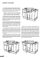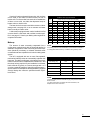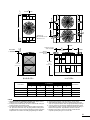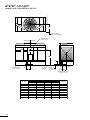
1
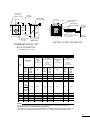
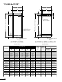
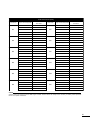
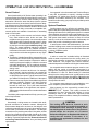
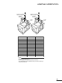
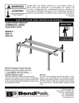
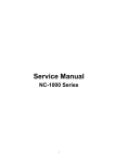
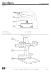
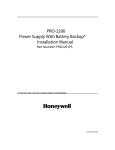
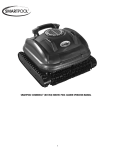
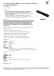
Marley Cooling Tower - 360 ton
Mfg: Marley
Stock No. 130.CJR1802.40
Model: NC4011GM
Serial No. 060597-001-94
Marley Cooling Tower - 360 ton.
•
•
•
•
Model NC4011GM
S/N 060597-001-94
Designed to cool 1080 gpm from 95.2-to 85.2 at a 78 °.
Similar to current NC4211 Model.
®
SERIES
Technical Reference
TOWER MODEL SELECTION
CTI
CERTIFIED
CERTIFIED
GPM Cooling capability at indicated Hot Water, Cold Water and Wet-Bulb temperatures
temp
Tower
Model
Motor
bhp
HW ° F
95
96
100
102
95
97
100
102
95
97
100
102
CW ° F
85
86
85
87
85
87
85
87
85
87
85
87
WB ° F
80
80
80
80
78
78
78
78
76
76
76
76
NC1201
5
334
379
268
336
405
490
320
384
469
551
367
428
NC1211
7.5
379
430
305
381
459
555
364
436
531
623
416
485
NC1221
10
414
469
333
416
501
605
397
476
580
680
454
530
NC2201
7.5
450
511
362
453
546
660
432
518
632
741
495
578
NC2211
10
503
570
405
506
609
736
482
578
705
826
552
644
NC2221
15
565
641
455
568
684
826
542
649
791
928
620
723
NC3201
10
563
637
457
567
678
815
541
645
781
912
616
716
NC3211
15
646
730
524
650
777
933
621
739
895
1043
707
820
NC3221
20
701
792
569
705
843
1012
673
802
971
1132
767
890
NC4201
15
779
877
636
784
933
1115
750
889
1070
1242
851
984
NC4211
20
849
956
692
854
1017
1215
817
969
1167
1354
928
1072
NC4221
25
909
1024
741
915
1089
1301
875
1037
1249
1448
993
1148
NC5201
20
1002
1134
815
1010
1209
1463
963
1150
1399
1646
1098
1280
NC5211
25
1074
1215
873
1082
1296
1568
1033
1233
1499
1764
1177
1372
NC5221
30
1118
1266
909
1127
1350
1634
1075
1284
1562
1838
1226
1430
NC5231
40
1246
1410
1014
1256
1503
1817
1198
1430
1737
2042
1366
1591
NC6201
25
1185
1338
967
1194
1425
1717
1140
1357
1643
1924
1297
1507
NC6211
30
1255
1417
1024
1265
1509
1817
1208
1437
1739
2036
1374
1596
NC6221
40
1368
1544
1117
1379
1644
1977
1317
1566
1893
2214
1497
1738
NC7201
25
1256
1415
1028
1266
1503
1799
1209
1434
1724
2005
1372
1587
NC7211
30
1327
1494
1085
1337
1587
1899
1277
1515
1820
2116
1448
1676
NC7221
40
1440
1621
1178
1451
1722
2058
1386
1644
1973
2292
1572
1818
NC7231
50
1557
1750
1277
1569
1857
2213
1500
1774
2123
2458
1698
1958
NC7241
55
1587
1786
1299
1600
1896
2262
1529
1810
2169
2515
1732
2000
NCA2A1
25
1323
1493
1081
1333
1590
1917
1273
1514
1834
2153
1448
1682
NCA2B1
30
1419
1601
1160
1429
1704
2052
1366
1623
1964
2302
1552
1802
NCA2C1
40
1549
1747
1265
1560
1860
2240
1490
1772
2144
2510
1694
1967
NCA201
25
1389
1567
1136
1399
1668
2008
1337
1589
1922
2252
1519
1764
NCA211
30
1477
1666
1207
1488
1773
2134
1421
1689
2043
2391
1615
1874
NCA221
40
1628
1836
1331
1640
1953
2347
1567
1861
2247
2626
1780
2064
NCB2A1
25
1404
1580
1150
1415
1677
2003
1352
1601
1920
2230
1532
1770
NCB2B1
30
1501
1687
1229
1512
1791
2136
1445
1710
2049
2376
1637
1889
NCB2C1
40
1623
1826
1328
1636
1938
2312
1563
1851
2217
2570
1771
2044
NCB2D1
50
1702
1914
1394
1715
2031
2420
1639
1940
2321
2688
1857
2142
NCB201
25
1468
1654
1201
1480
1758
2106
1413
1677
2017
2349
1604
1857
NCB211
30
1555
1751
1272
1567
1860
2225
1497
1775
2133
2479
1698
1964
NCB221
40
1697
1910
1388
1710
2028
2423
1633
1936
2323
2695
1852
2140
NCB231
50
1778
2004
1452
1792
2130
2551
1711
2032
2444
2843
1943
2250
NCB241
60
1880
2118
1536
1894
2250
2691
1809
2147
2579
2995
2053
2376
2
CTI
CERTIFIED
CERTIFIED
GPM cooling capability at indicated Hot Water, Cold Water and Wet-Bulb temperatures
temp
Tower
Model
Motor
bhp
HW ° F
95
96
100
102
95
97
100
102
95
97
100
102
CW ° F
85
86
85
87
85
87
85
87
85
87
85
87
WB ° F
80
80
80
80
78
78
78
78
76
76
76
76
NC8201
25
1542
1730
1267
1554
1833
2173
1486
1753
2088
2404
1679
1931
NC8211
30
1636
1835
1345
1648
1944
2303
1577
1859
2213
2547
1781
2047
NC8221
40
1784
2000
1467
1797
2118
2506
1720
2026
2409
2768
1942
2230
NC8231
50
1973
2206
1627
1988
2334
2748
1903
2235
2645
3025
2144
2454
NC8241
60
2065
2309
1703
2080
2442
2875
1992
2339
2767
3164
2243
2567
NC9201
25
1704
1907
1404
1717
2019
2385
1643
1932
2293
2632
1852
2124
NC9211
30
1787
2001
1472
1800
2118
2502
1723
2027
2406
2762
1943
2229
NC9221
40
1984
2218
1637
1998
2346
2763
1913
2247
2659
3043
2155
2467
NC9231
50
2111
2360
1741
2126
2496
2939
2036
2390
2828
3235
2293
2624
NC9241
60
2258
2519
1869
2275
2661
3119
2180
2551
3005
3424
2449
2794
NC9251
75
2403
2676
1993
2420
2823
3295
2321
2709
3178
3498*
2603
2961
NC9261
75
2562
2847
2130
2580
3000
3486
2476
2881
3367
3498*
2771
3142
NCC201
25
1902
2132
1569
1917
2259
2682
1834
2160
2575
2974
2070
2380
NCC211
30
2007
2248
1655
2022
2382
2826
1935
2278
2714
3131
2183
2509
NCC221
40
2209
2473
1822
2225
2619
3101
2130
2506
2979
3430
2402
2757
NCC231
50
2407
2693
1987
2425
2850
3367
2321
2728
3237
3591*
2615
2999
NCC241
60
2437
2730
2007
2455
2892
3427
2349
2766
3292
3792
2651
3045
NCC251
75
2619
2933
2160
2639
3105
3672
2526
2971
3529
4057
2848
3268
NCC261
75
2819
3135
2344
2839
3306
3857
2723
3173
3721
4100*
3050
3466
• Thermal performance of the NC Series has been certified by CTI (Cooling Tower Institute) in accordance with CTI Standard
STD-201(96), and has been assigned CTI certification validation number 92-14-01.
• CTI Certification under STD-201(96) applies ONLY to selections with entering water temperature of 125°F or less, temperature ranges of 4°F or more, temperature approaches of 5°F or more, and wet bulb temperatures between 60°F and 85°F.
* Indicates maximum hydraulic limit.
3
TOWER MODEL SELECTION
CTI
CERTIFIED
CERTIFIED
GPM Cooling capability at indicated Hot Water, Cold Water and Wet-Bulb temperatures
temp
HW ° F
95
100
90
95
90
95
90
95
90
95
90
95
CW ° F
85
85
80
80
80
80
80
80
80
80
80
80
Tower
Model
Motor
bhp
75
75
72
72
70
70
68
68
66
66
64
64
NC1201
5
499
389
391
306
448
347
500
384
548
419
593
452
NC1211
7.5
565
441
444
347
507
393
566
436
620
475
671
512
NC1221
10
616
481
484
379
553
429
617
475
676
518
731
558
NC2201
7.5
672
524
528
413
603
468
673
518
737
565
798
609
NC2211
10
749
585
589
461
673
522
750
578
821
630
888
679
NC2221
15
841
657
661
518
755
586
842
649
923
708
997
762
NC3201
10
829
652
656
518
747
584
831
645
909
702
981
755
NC3211
15
949
747
752
594
856
670
951
740
1039
804
1121
865
NC3221
20
1030
810
816
644
928
727
1032
802
1128
873
1217
938
NC4201
15
1133
898
903
718
1024
807
1135
889
1236
964
1329
1034
NC4211
20
1236
979
985
782
1117
879
1237
968
1347
1051
1449
1127
NC4221
25
1323
1048
1054
837
1195
942
1324
1037
1441
1125
1549
1207
NC5201
20
1488
1162
1166
920
1331
1037
1486
1146
1630
1248
1767
1345
NC5211
25
1595
1246
1250
986
1427
1111
1592
1228
1747
1338
1893
1441
NC5221
30
1662
1297
1302
1026
1487
1157
1659
1280
1820
1394
1972
1501
NC5231
40
1848
1445
1450
1144
1654
1290
1845
1425
2022
1552
2189
1671
NC6201
25
1745
1371
1375
1090
1566
1226
1742
1352
1906
1470
2060
1581
NC6211
30
1847
1452
1456
1154
1658
1298
1844
1432
2017
1557
2179
1674
NC6221
40
2010
1582
1587
1258
1805
1415
2007
1560
2194
1696
2368
1822
NC7201
25
1826
1447
1449
1155
1643
1296
1820
1426
1983
1546
2134
1657
NC7211
30
1927
1528
1531
1219
1734
1368
1921
1505
2092
1632
2251
1750
NC7221
40
2089
1658
1661
1323
1881
1485
2082
1634
2267
1771
2437
1898
NC7231
50
2245
1789
1792
1433
2026
1605
2237
1763
2431
1909
2610
2043
WB ° F
NC7241
55
2295
1826
1829
1459
2069
1637
2288
1799
2487
1949
2671
2088
NCA2A1
25
1950
1529
1535
1217
1747
1368
1946
1509
2132
1641
2307
1765
NCA2B1
30
2087
1639
1645
1305
1872
1467
2083
1617
2280
1758
2465
1890
NCA2C1
40
2277
1790
1795
1425
2043
1601
2273
1766
2487
1919
2688
2063
NCA201
25
2042
1605
1610
1278
1832
1436
2038
1583
2231
1721
2411
1850
NCA211
30
2169
1706
1712
1359
1947
1527
2166
1683
2369
1829
2560
1966
NCA221
40
2385
1880
1886
1498
2143
1683
2381
1855
2602
2014
2808
2164
NCB2A1
25
2033
1615
1618
1291
1831
1448
2026
1592
2205
1724
2371
1847
NCB2B1
30
2168
1725
1728
1380
1954
1548
2161
1700
2350
1841
2524
1972
NCB2C1
40
2346
1867
1870
1492
2115
1674
2338
1840
2542
1992
2731
2134
NCB2D1
50
2455
1957
1960
1565
2215
1755
2447
1928
2659
2088
2760*
2235
NCB201
25
2138
1692
1695
1349
1922
1515
2131
1667
2323
1808
2500
1940
NCB211
30
2259
1791
1794
1429
2033
1604
2251
1764
2452
1913
2637
2051
NCB221
40
2458
1953
1956
1559
2215
1750
2450
1924
2666
2085
2864
2235
NCB231
50
2589
2050
2054
1633
2329
1834
2580
2020
2811
2191
3024
2350
NCB241
60
2731
2166
2170
1727
2459
1939
2722
2134
2962
2314
3183
2481
4
CTI
CERTIFIED
CERTIFIED
GPM cooling capability at indicated Hot Water, Cold Water and Wet-Bulb temperatures
temp
Tower
Model
Motor
bhp
HW ° F
95
100
90
95
90
95
90
95
90
95
90
95
CW ° F
85
85
80
80
80
80
80
80
80
80
80
80
WB ° F
75
75
72
72
70
70
68
68
66
66
64
64
NC8201
25
2204
1768
1770
1420
1995
1589
2197
1742
2380
1883
2546
2012
NC8211
30
2335
1875
1878
1507
2115
1686
2328
1848
2521
1997
2696
2133
NC8221
40
2541
2043
2047
1644
2303
1838
2533
2014
2740
2175
2927
2322
NC8231
50
2785
2253
2257
1820
2532
2032
2777
2222
2995
2395
3192
2553
NC8241
60
2913
2358
2362
1905
2649
2126
2904
2325
3133
2506
3194*
2671
NC9201
25
2418
1948
1951
1571
2193
1755
2410
1921
2606
2073
2783
2212
NC9211
30
2537
2044
2047
1648
2301
1841
2529
2015
2734
2174
2921
2321
NC9221
40
2801
2265
2269
1830
2546
2043
2792
2234
3013
2408
3213
2566
NC9231
50
2978
2410
2414
1948
2708
2174
2969
2377
3204
2561
3415
2730
NC9241
60
3160
2572
2575
2087
2881
2324
3151
2537
3391
2729
3498*
2904
NC9251
75
3336
2730
2734
2223
3050
2472
3327
2694
3498*
2893
3498*
3074
NC9261
75
3498*
2903
2908
2373
3235
2634
3498*
2866
3498*
3073
3498*
3259
NCC201
25
2721
2179
2182
1754
2460
1960
2712
2147
2943
2320
3154
2481
NCC211
30
2866
2297
2301
1850
2593
2067
2857
2265
3099
2447
3319
2615
NCC221
40
3144
2527
2531
2038
2848
2275
3134
2491
3394
2689
3631
2872
NCC231
50
3414
2751
2755
2221
3097
2479
3403
2712
3591*
2926
3591*
3122
NCC241
60
3475
2790
2794
2246
3146
2510
3464
2750
3752
2970
4016
3173
NCC251
75
3723
2996
3001
2416
3375
2698
3711
2954
4016
3188
4100*
3403
NCC261
75
3906
3198
3203
2610
3571
2899
3895
3156
4100*
3388
4100*
3598
• Thermal performance of the NC Series has been certified by CTI (Cooling Tower Institute) in accordance with CTI Standard
STD-201(96), and has been assigned CTI certification validation number 92-14-01.
• CTI Certification under STD-201(96) applies ONLY to selections with entering water temperature of 125°F or less, temperature ranges of 4°F or more, temperature approaches of 5°F or more, and wet bulb temperatures between 60°F and 85°F.
* Indicates maximum hydraulic limit.
5
TOWER SCHEMATIC
EXCEPT FOR MODEL NC1220, DIMENSION “A”
REPEATS FOR ANY NUMBER OF CELLS.
MODEL NC1220 REQUIRES SPECIAL SPACING
FOR 3 OR MORE CELLS.
MOTOR ENCLOSURE PROTRUSION
MODEL NC1220 ONLY
W
31/2 "
Marley
H
INSTALLED
HEIGHT
HINGED ACCESS
DOOR
6
A MIN
CL
101/8"
L
CL
MIN
Tower Model
Nominal Tons
Note 2
Note 3
NC1201
135
NC1211
153
NC1221
NC2201
Motor hp
Design
Operating
Wt/Cell
lb
Shipping
Weight
lb
DIMENSIONS
W
L
H
A
14′-0″
4268mm
6′-4 ³⁄₄″
1950mm
10′-1 ⁵⁄₈″
3090mm
6′-8 ¹⁄₄″
2039mm
5
9,129
4,541
7 ¹⁄₂
9,180
4,591
167
10
9,298
4,709
182
7 ¹⁄₂
11,589
5,332
15′-6″
4725mm
7′-10 ³⁄₄″
2407mm
10′-2 ³⁄₈″
3109mm
8′-2 ¹⁄₄″
2496mm
NC2211
203
10
11,615
5,358
NC2221
228
15
11,699
5,442
NC3201
226
10
12,021
5,764
NC3211
259
15
12,104
5,848
NC3221
281
20
12,165
5,909
NC4201
311
15
14,615
6,940
NC4211
339
20
14,692
7,017
NC4221
363
25
14,749
7,074
NC5201
403
20
19,275
8,980
NC5211
432
25
19,353
9,059
NC5221
450
30
19,415
9,121
NC5231
501
40
19,681
9,387
NC6201
475
25
21,834
10,021
NC6211
503
30
21,896
10,083
NC6221
548
40
22,039
10,226
NC7201
501
25
26,315
11,257
NC7211
529
30
26,377
11,319
15′-6″
4725mm
17′-0″
5182mm
18′-9″
5715mm
19′-10″
6046mm
22′-5″
6833mm
7′-10 ³⁄₄″
2407mm
8′-10 ³⁄₄″
2712mm
10′-10 ³⁄₄″
3321mm
11′-10 ³⁄₄″
3626mm
11′-11 ¹⁄₄″
3638mm
12′-11 ³⁄₄″
3956mm
12′-11 ³⁄₄″
3956mm
12′-11 ³⁄₄″
3956mm
11′-10 ³⁄₄″
3626mm
13′-3 ³⁄₄″
4058mm
8′-2 ¹⁄₄″
2496mm
9′-2 ¹⁄₄″
2801mm
11′-2 ¹⁄₄″
3410mm
12′-2 ¹⁄₄″
3715mm
12′-2 ¹⁄₄″
3715mm
NC7221
574
40
26,520
11,462
NC7231
619
50
26,586
11,528
NC7241
632
60
26,858
11,800
NCA2A1
530
25
27,314
12,048
22′-5″
6833mm
13′-10 ³⁄₄″
4236mm
12′-11 ³⁄₄″
3956mm
14′-2 ¹⁄₄″
4325mm
NCA2B1
568
30
27,376
12,110
NCA2C1
619
40
27,729
12,463
NCA201
556
25
27,211
11,945
NCA211
591
30
27,273
12,007
22′-5″
6833mm
13′-10 ³⁄₄″
4236mm
12′-11 ³⁄₄″
3956mm
14′-2 ¹⁄₄″
4325mm
NCA221
651
40
27,416
12,150
NCB2A1
559
25
30,659
13,063
NCB2B1
597
30
30,721
13,125
NCB2C1
646
40
31,074
13,478
NCB2D1
677
50
31,140
13,544
NCB201
586
25
30,556
12,960
NCB211
620
30
30,618
13,022
NCB221
676
40
30,761
13,165
NCB231
710
50
31,180
13,584
NCB241
750
60
31,452
13,856
22′-5″
6833mm
22′-5″
6833mm
13′-10 ³⁄₄″
4236mm
13′-10 ³⁄₄″
4236mm
13′-3 ³⁄₄″
4058mm
13′-3 ³⁄₄″
4058mm
14′-2 ¹⁄₄″
4325mm
14′-2 ¹⁄₄″
4325mm
NOTE
1 Use this bulletin for preliminary layouts only. Obtain current
drawings from your Marley sales representative. All table data is
per cell.
2 Last numeral of model number indicates number of cells. Change
as appropriate for your selection.
3 Nominal tons are based upon 95°F HW, 85°F CW, 78°F WB and
3 GPM/ton.
4 Standard overflow is a 4″ dia. standpipe in the collection basin
floor. The standpipe removes for flush-out and draining. See
page 16 for side overflow option.
5 Outlet sizes vary according to GPM and arrangement. See pages
16 and 17 for outlet sizes and details.
6 Makeup water connection may be 1″ or 2″ dia., depending upon
tower heat load, water pressure, and desired connections. See
page 11 for additional information.
7
TOWER SCHEMATIC
CL
22' 5"
Marley
H
INSTALLED
HEIGHT
HINGED ACCESS
DOOR
8
L
A MIN
B
CL
MIN
Tower Model
Nominal Tons
Note 2
Note 3
DIMENSIONS
L
H
A
B
Shipping Weight
lb
Design
Operating
Wt/Cell
lb
Motor hp
Weight/Cell
Heaviest
Section
NC8201
611
33,014
25
15,337
8,338
NC8211
648
33,076
30
15,399
8,400
NC8221
706
33,219
40
15,542
8,543
NC8231
778
33,285
50
15,608
8,609
NC8241
814
33,557
60
15,880
8,881
NC9201
673
35,689
25
16,335
8,838
NC9211
706
35,751
30
16,397
8,900
NC9221
782
35,815
40
16,461
8,964
NC9231
832
35,881
50
16,527
9,030
NC9241
887
36,153
60
16,799
9,302
NC9251
941
36,292
75
16,938
9,441
NC9261
1,000
36,372
75
17,018
9,521
NCC201
753
41,545
25
18,905
9,997
NCC211
794
41,607
30
18,967
10,059
NCC221
873
41,751
40
19,110
10,202
NCC231
950
41,817
50
19,176
10,268
NCC241
964
42,299
60
19,658
10,750
NCC251
1035
42,354
75
19,718
10,810
NCC261
1,102
42,451
75
19,810
10,902
10′-10 ³⁄₄″
3321mm
11′-10 ³⁄₄″
3626mm
12′-8 ⁵⁄₈″
3877mm
13′-10 ³⁄₄″
4236mm
13′-10 ³⁄₄″
4236mm
19′-9 ³⁄₄″
6039mm
19′-9 ³⁄₄″
6039mm
23′-4″
7112mm
19′-9 ³⁄₄″
6039mm
23′-4″
7112mm
11′-2 ¹⁄₄″
3410mm
12′-2 ¹⁄₄″
3715mm
12′-9 ¹⁄₂″
3899mm
14′-2 ¹⁄₄″
4325mm
14′-2 ¹⁄₄″
4325mm
3 ¹⁄₂″
89mm
3 ¹⁄₂″
89mm
10 ³⁄₄″
273mm
3 ¹⁄₂″
89mm
3 ¹⁄₂″
89mm
NOTE
1 Use this bulletin for preliminary layouts only. Obtain current
drawings from your Marley sales representative. All table data is
per cell.
2 Last numeral of model number indicates number of cells. Change
as appropriate for your selection.
3 Nominal tons are based upon 95°F HW, 85°F CW, 78°F WB and
3 GPM/ton.
4 Standard overflow is a 4″ dia. standpipe in the collection basin
floor. The standpipe removes for flush-out and draining. See
page 16 for side overflow option.
5 Outlet sizes vary according to GPM and arrangement. See pages
16 and 17 for outlet sizes and details.
6 Makeup water connection may be 1″ or 2″ dia., depending upon
tower heat load, water pressure, and desired connections. See
page 11 for additional information.
9
SYSTEM CONNECT
Tired of having to design your piping and tower layout to
accommodate the standards of cooling tower manufacturers? Marley’s SystemConnect™ variety of piping systems
accommodates your design intentions to make your layout
of the NC Series both expedient and economical.
• Single or dual hot water inlet connections.
• Side inlet, bottom inlet or top inlet connections.
• Side or bottom cold water outlet connections.
• A variety of makeup, overflow and drain options.
All piping from the single inlet connection to the distribution basins is part of the tower package. Installation and
design costs are reduced and the need for extra piping and
supports are eliminated. The single bottom inlet connection
is perfect for multicell applications—keeping all the inlet
piping below the tower.
Unless otherwise specified, single-cell towers normally
have a side-outlet suction appropriate for the design water
flow rate—see pages 16 and 17. This usually assures the
lowest possible installed tower elevation. Side-suction connection pipes extend roughly 3″ outside the basin, and are
beveled for weld connection and also grooved for a mechanical coupling.
Outlet piping can be kept below the cold water basin
level by choosing either a depressed sump or a bottom
outlet connection in lieu of the side suction. Both outlet
designs conform to standard class 125 ANSI pipe flange
specifications. Easily removable debris screens are optional on bottom outlets and are standard on all other outlet
arrangements.
Depressed sumps are made of inert FRP or heavygauge welded stainless steel. Unless otherwise specified
towers with galvanized steel collection basins are supplied
with FRP sumps and towers with stainless steel basins are
supplied with stainless sumps.
10
Multicell towers, intended to operate together as a
common unit, are joined by steel flumes between the
collection basins. These flumes equalize the operating
water level between basins and also provide a flow passage from cells not equipped with outlets or makeup valves,
often eliminating the need to specify an outlet and makeup
valve for each cell on a multicell installation. Select the
number of outlets required to maintain a maximum flow of
1,371 GPM through each flume for NC1 through NC6 and
NCA models and 2,203 GPM for NC7 through NC9 and
NCB through NCC models. Flow values are for sidesuctions or bottom-outlets without trash screen. Refer to
NC sales drawings to obtain flow values for sumps and
bottom outlets with trash screens.
If each cell is to be equipped with an outlet, side-suctions
can be used on end cells of multicell towers, but not on
interior cells. For direct outlet from each cell on installations
of three or more cells, use either the depressed sump or
bottom outlet on interior cells.
The best choice for a tower used with a remote or indoor
storage tank—see page 20—or on a concrete cold water
basin is usually a bottom outlet.
A side-suction equipped tower can be installed on a flat
concrete slab if a side drain and overflow are also specified—see page 16. Consult your Marley sales engineer for
complete information.
Makeup
The amount of water constantly evaporated from a
cooling tower varies directly with the heat load applied. In
addition to evaporation, water is normally lost to the blowdown (bleed-off) necessary to maintain dissolved solids
concentration at an acceptable level in the circulating water
system.
The NC is equipped with one or more float-operated,
mechanical makeup valves to automatically replenish this
lost water. The tables on this page, calculated for a concentration of 3 times normal, indicate the rate of water loss—and
the size of valve(s) required. If your installation’s cold water
basin will drain by gravity to a remote storage tank—or if
you plan a separate means of controlling makeup water—
a price reduction is available for deleting the Marley-supplied
valve(s). Marley also offers an optional electronic liquid level contol.
Makeup Water Flow Required–GPM
to Maintain Three (3) Concentrations
Cooling “Range” (hot water minus cold water)
Tower
GPM
5° F
10° F
15° F
20° F
30° F
40° F
200
2
3
4
5
8
10
400
3
5
8
10
15
20
600
4
8
12
15
23
30
800
5
10
15
20
30
40
1,000
7
13
19
25
38
50
1,500
10
19
29
38
57
75
2,000
13
25
38
50
75
100
3,000
19
38
57
75
113
150
4,000
25
50
75
100
150
200
5,000
32
63
94
125
188
250
6,000
38
75
113
150
225
300
8,000
50
100
150
200
300
400
NOTE
If circulating water is to be maintained at 2 concentrations instead of
3, multiply table GPM values by 1.36 before sizing makeup valve.
Makeup Valve Flow Capacities–GPM
Pressure at Valve Inlet
while flowing–psig
1″ Diameter
Valve
2″ Diameter
Valve
10
56
90
20
78
120
30
92
143
40
106
160
50
117
167
NOTE
• If makeup water pressure exceeds 50 psig, use pressure reducer
ahead of valve.
• For flow requirements exceeding the above limitations, use
multiples of the same size valve.
11
SYSTEM CONNECT
TOWER CL INLET
CL INLET
CL INLET
DUAL INLET CONNECTION
K
Q
CL INLET
NOTE 7
CL INLET
MARLEY HC
BALANCING VALVE
OPTION NOTE 6
CL TOWER
CL INLET
PIPING
FACE OF VALVE
INLET FLANGE
INCLUDES
1/4" GASKET
TOP OF
DISTRIBUTION
BASIN
P
N
INCLUDES
1/4" GASKET
MIN/MAX
CL HEADER
Marley
S
J
USE FOR
STATIC LIFT
INLET
ELEVATION
SINGLE CELL
MULTICELL
DIMENSIONS
Tower Model
J
12
K
S
N
Inlet Diameter
P
MIN/MAX
Q
NC1200
8′-8 ¹¹⁄₁₆″
12′-3″
9′-4 ¹⁵⁄₁₆″
3′-11 ¹⁄₂″
4′-10″
5′-10″
6′-8 ¹⁄₄″
2 at 6″
NC2200
8′-8 ¹¹⁄₁₆″
13′-9″
9′-4 ¹⁵⁄₁₆″
5′-10 ¹⁄₄″
Fit “ P”
6′-7″
8′-2 ¹⁄₄″
2 at 6″
NC3200
10′-5 ⁹⁄₁₆″
13′-9″
11′-1 ¹³⁄₁₆″
5′-10 ¹⁄₄″
Fit “ P”
6′-7″
8′-2 ¹⁄₄″
2 at 6″
NC4200
11′-5 ⁹⁄₁₆″
15′-3″
12′-1 ¹³⁄₁₆″
5′-10 ¹⁄₄″
Fit “ P”
7′-4″
9′-2 ¹⁄₄″
2 at 6″
NC5200
11′-5 ⁹⁄₁₆″
16′-10″
12′-2 ¹³⁄₁₆″
5′-11 ³⁄₄″
Fit “ P”
8′-1 ¹⁄₂″
11′-2 ¹⁄₄″
2 at 8″
NC6200
11′-5 ⁹⁄₁₆″
17′-11″
12′-2 ¹³⁄₁₆″
6′-1 ⁵⁄₈″
Fit “ P”
8′-8″
12′-2 ¹⁄₄″
2 at 8″
NC7200
11′-9 ⁹⁄₁₆″
20′-6″
12′-6 ¹³⁄₁₆″
6′-1 ⁵⁄₈″
Fit “ P”
9′-11 ¹⁄₂″
12′-2 ¹⁄₄″
2 at 8″
NCA200
11′-5 ⁹⁄₁₆″
20′-6″
12′-2 ¹³⁄₁₆″
6′-10 ⁵⁄₈″
Fit “ P”
9′-11 ¹⁄₂″
14′-2 ¹⁄₄″
2 at 8″
NCB200
11′-9 ⁹⁄₁₆″
20′-3 ¹⁄₂″
12′-8 ¹³⁄₁₆″
6′-10 ⁵⁄₈″
Fit “ P”
9′-9 ¹⁄₂″
14′-2 ¹⁄₄″
2 at 10″
CL INLET
CL INLET
TOWER CL INLET
K
CL INLET
Q
CL INLET
MARLEY HC
BALANCING VALVE
OPTION NOTE 6
CL TOWER
CL INLET
PIPING
FACE OF VALVE
INLET FLANGE
INCLUDES
GASKET
1/4"
P
N
INCLUDES
1/4" GASKET
TOP OF
DISTRIBUTION
BASIN
CL HEADER
Marley
18'-3 9/16"
INLET
ELEVATION
S
USE FOR
STATIC LIFT
SINGLE CELL
MULTICELL
DIMENSIONS
Tower Model
Inlet Diameter
K
S
N
Q
P
NC8200
20′-6″
19′-0 ¹³⁄₁₆″
6′-1 ⁵⁄₈″
11′-2 ¹⁄₄″
9′-11 ¹⁄₂″
2 at 8″
NC9200 thru NC9250
20′-6″
19′-0 ¹³⁄₁₆″
6′-1 ⁵⁄₈″
12′-2 ¹⁄₄″
9′-11 ¹⁄₂″
2 at 8″
NC9260
20′-6″
19′-0 ¹³⁄₁₆″
6′-1 ⁵⁄₈″
12′-9 ¹⁄₂″
9′-11 ¹⁄₂″
2 at 8″
NCC200
20′-3 ¹⁄₂″
19′-2 ⁹⁄₁₆″
6′-10 ⁵⁄₈″
14′-2 ¹⁄₄″
9′-9 ¹⁄₂″
2 at 10″
NOTE
1 Use this bulletin for preliminary layouts only. Obtain current
drawings from your Marley sales representative.
2 Pumping head contributed by the tower is static lift “S”. Add your
system dynamic pipe losses for total.
3 The tower will support the vertical weight of piping shown within
the plan area of the tower only. All piping loads, including thrust
and lateral loads of riser and horizontal piping must be supported
independent of the tower. See inlet piping drawings for details.
4 All piping and supports—and their design—are by others.
5 Allow adequate clearance for entry to tower access doors and
safe use of optional ladder. Refer to appropriate Marley drawings.
6 You may choose to use 90° short radius flanged elbows in place
of HC balancing valves on single-cell towers where inlet piping is
balanced for equal flow. Pipe elevation remains as shown.
7 Because of the motor enclosure protrusion model NC1220
requires special spacing for 3 or more cells.
13
SYSTEM CONNECT
CL TOWER CELL
SINGLE INLET CONNECTION OPTION
C
FACE OF SIDE
INLET CONNECTION
SINGLE SIDE
INLET NOTE 5
CL INLET
SIDE INLET CL TOWER
Marley
B
6"
CLINLET
SINGLE BOTTOM
INLET NOTE 5
FACE OF
BOTTOM INLET
CONNECTION
TOP OF
SUPPORT
D
CLINLET CLTOWER
E
SINGLE BOTTOM
INLET NOTE 5
DIMENSIONS
Tower Model
B
14
C
D
E
Inlet
Diameter
NC1200
6′-8 ¹⁄₄″
3′-0 ⁵⁄₁₆″
2′-8″
1′-11 ¹³⁄₁₆″
6″
NC2200
6′-6 ¹⁵⁄₁₆″
3′-9 ⁵⁄₁₆″
2′-8″
2′-5 ⁵⁄₁₆″
8″
NC3200
8′-3 ¹³⁄₁₆″
3′-9 ⁵⁄₁₆″
2′-8″
2′-5 ⁵⁄₁₆″
8″
NC4200
9′-3 ¹³⁄₁₆″
4′-3 ⁵⁄₁₆″
2′-10 ³⁄₈″
2′-11 ⁵⁄₁₆″
8″
NC5200
9′-3 ³⁄₁₆″
5′-3 ⁵⁄₁₆″
2′-8 ⁷⁄₈″
1′-4 ¹⁄₈″
10″
NC6200
9′-3 ³⁄₁₆″
5′-9 ⁵⁄₁₆″
2′-8 ⁷⁄₈″
2′-9 ³⁄₈″
10″
NC7200
9′-7 ³⁄₁₆″
5′-9 ⁵⁄₁₆″
2′-8 ⁷⁄₈″
2′-9 ³⁄₈″
10″
NCA200
9′-3 ³⁄₁₆″
6′-9 ⁵⁄₁₆″
2′-4″
3′-7 ⁷⁄₁₆″
10″
NCB200
9′-7 ³⁄₁₆″
6′-9 ⁵⁄₁₆″
2′-4″
1′-2 ⁵⁄₁₆″
10″
CL TOWER CELL
C
FACE OF 10" DIA. SIDE
INLET CONNECTION
SINGLE SIDE
INLET NOTE 5
CL INLET
10" SIDE INLET CL TOWER
Marley
16' 1 3/16"
6"
TOP OF
SUPPORT
10" INLET CL
D
CLINLET CLTOWER
FACE OF
10" DIA. BOTTOM
INLET CONNECTION
E
SINGLE BOTTOM
INLET NOTE 5
SINGLE BOTTOM
INLET NOTE 5
Tower Model
NC8200
C
DIMENSIONS
D
E
5′-3 ⁵⁄₁₆″
2′-5 ³⁄₈″
3′-10 ¹⁄₈″
NC9200
5′-9 ⁵⁄₁₆″
2′-5 ³⁄₈″
4′-4 ¹⁄₈″
NCC200
6′-9 ⁵⁄₁₆″
2′-4 ¹⁄₄″
3′-4 ¹⁄₈″
NOTE
1 Use this bulletin for preliminary layouts only. Obtain current
drawings from your Marley sales representative.
2 All external piping loads, including weight, thrust and lateral loads
of riser and horizontal piping plus the weight of water in the
internal riser must be supported independent of the tower.
Internal riser adds additional vertical operating loads to external
piping at the bottom inlet flange.
3 All piping and supports beyond the inlet connection—and their
design—are by others.
4 Allow adequate clearance for entry to tower access doors and
safe use of optional ladder. Refer to appropriate Marley
drawings.
5 You may choose either a bottom inlet connection or a
side inlet connection. The bottom inlet connects at the tower
collection basin floor. Refer to appropriate Marley drawings.
6 Contact your Marley sales representative for the required pump
head for single-inlet applications.
7. Weight of internal piping must be added to tower weights. Contact
your Marley sales representative for combined tower weight
information.
15
SYSTEM CONNECT
OUTLET CONNECTION
DIMENSIONS
Tower Model
CLTOWER
SUCTION CONNECTION
SEE TABLE FOR SIZE
OVERFLOW
3" DIA NPTF
NC1200
C
CL
CL
DRAIN AND CLEAN-OUT
1 1/2 " DIA NPTF
4 9/16"
12 7/8 "
CL
CL
A
B
C
10″
3′-3 ³⁄₁₆″
6 ⁷⁄₈″
NC2200
10″
4′-0 ³⁄₁₆″
6 ⁷⁄₈″
NC3200
10″
4′-0 ³⁄₁₆″
6 ⁷⁄₈″
NC4200
10″
4′-6 ³⁄₁₆″
6 ⁷⁄₈″
NC5200
10″
5′-6 ³⁄₁₆″
6 ⁷⁄₈″
NC6200
10″
6′-0 ³⁄₁₆″
6 ⁷⁄₈″
NC7200
11¹⁄₄″
6′-0 ³⁄₁₆″
10 ³⁄₁₆″
NC8200
11¹⁄₄″
5′-6 ³⁄₁₆″
10 ³⁄₁₆″
NC9200
11¹⁄₄″
6′-0 ³⁄₁₆″
10 ³⁄₁₆″
NCA200
10″
7′-0 ³⁄₁₆″
6 ⁷⁄₈″
DRAIN AND OVERFLOW CONNECTION
NCB200
11¹⁄₄″
7′-0 ³⁄₁₆″
10 ³⁄₁₆″
OPTION
NCC200
11¹⁄₄″
7′-0 ³⁄₁₆″
10 ³⁄₁₆″
TOP OF
SUPPORT
TOWER CL
WELDING
BEVEL
MECHANICAL
COUPLING GROOVE
SUCTION HOOD
REMOVABLE
TRASH SCREEN
A
SUCTION CONNECTION
SEE TABLE FOR SIZE
TOP OF
SUPPORT
B
SECTON
SIDE-OUTLET SUCTION CONNECTION
16
CL TOWER CELL
BOTTOM OF
COLLECTION
BASIN FLOOR
TOP OF
SUPPORT
REMOVABLE
TRASH SCREEN
CL SUMP
1
OUTLET
SEE TABLE FOR SIZE
TOWER COLLECTION
BASIN FLOOR
3/8"
CL OUTLET
REMOVABLE
TRASH SCREEN
1'-8 3/8"
2'-7 5/8"
SECTION
CL TOWER
CELL
NOTE BOTTOM OUTLET IS
ALSO AVAILABLE WITHOUT
TRASH SCREEN.
1'-1 7/8"
2'-4 3/4"
SUMP OUTLET
SEE TABLE
FOR SIZE
3/8"
2'-4
MIN CLEARANCE
SECTION
BOTTOM
OF BASIN
FLOOR
1 3/8"
TOP OF
SUPPORT
BOTTOM OUTLET CONNECTION
DEPRESSED SIDE-OUTLET
SUMP CONNECTION
STAINLESS STEEL OR FRP
Maximum GPM per Outlet
Sump
Sump
Side Suction
pump flow
pump flow
w/o
anti-vortex plate
Outlet
Dia
NC1
thru
NC6
NC7
thru
NC9
NCA
NCB
NCC
Bottom Outlet
pump flow
w/ anti-vortex plate
or
gravity flow
w/ or w/o
anti-vortex plate
Bottom Outlet
pump flow
w/o
anti-vortex plate
pump flow
w/ anti-vortex plate
or
gravity flow
w/ or w/o
anti-vortex plate
NC1
thru
NC6
NC7
thru
NC9
NCA
NCB
NCC
71
157
630
895
900
162
355
ALL
4″
ALL
NC1
thru
NC6
NC7
thru
NC9
NCA
NCB
NCC
6″
900
8″
1,595
1,595
1,116
1,584
1,595
287
629
673
10″
2,515
2,515
1,760
2,498
2,515
453
992
1,061
3,578
2,504
3,458
3,578
644
1,412
1,509
4,252
3,065
3,458
4,378
2,720
12″
NC1
thru NC4
3,501
NC5 NC6
NCA
14″
788
1,728
1,847
16″
1,041
2,283
2,441
18″
1,349
2,958
3,162
20″
1,675
3,321
4,045
24″
2,433
4,018
4,897
NOTE
• For gravity-flow situations (as to an indoor tank), use bottom outlet or depressed side outlet sump.
Side outlet suction is not recommended for gravity flow.
• GPM limits are the outlet capacities per outlet based on the design operating water level—8¹⁄₂″ above the
top of support on models NC1 through NC6 and NCA— 9¹⁄₂″ on NC7 through NC9 and NCB and NCC.
17
TOWER SUPPORT
L
L
OVERALL OF BASIN
OVERALL OF BASIN
D
CL ANCHOR
BOLT
CL ANCHOR
BOLT
ANCHOR CL
BOLT
ANCHOR CL
BOLT
2 1/4"
C
HOLES FOR
5/8" DIA. ANCHOR
BOLTS 4 REQD
2 1/4"
1"
ANCHORCL
BOLT
A
HOLES FOR
DIA. ANCHOR
BOLTS 4 REQD
5/8"
C
CL ANCHOR
BOLT
W OVERALL WIDTH OF BASIN
B
CL ANCHOR
BOLT
W OVERALL WIDTH OF BASIN
2 1/4"
D
1"
1"
ANCHOR CL
BOLT
1"
2 1/4"
TOWER COLLECTION
BASIN
TOWER COLLECTION
BASIN
SUPPORTING STEEL
SUPPORTING STEEL ALTERNATE
SINGLE CELL
SINGLE CELL
DIMENSIONS
Tower Model
NC1200
NC2200
NC3200
NC4200
NC5200
NC6200
NC7200
NC8200
NC9200 thru
NC9250
NC9260
NCA200
NCB200
NCC200 thru
NCC250
NCC260
18
W
L
C
D
14′-0″
4268mm
15′-6″
4725mm
15′-6″
4725mm
17′-0″
5182mm
18′-9″
5715mm
19′-10″
6046mm
22′-5″
6833mm
22′-5″
6833mm
22′-5″
6833mm
22′-5″
6833mm
22′-5″
6833mm
22′-5″
6833mm
22′-5″
6833mm
22′-5″
6833mm
6′-4 ³⁄₄″
1950mm
7′-10 ³⁄₄″
2407mm
7′-10 ³⁄₄″
2407mm
8′-10 ³⁄₄″
2712mm
10′-10 ³⁄₄″
3321mm
11′-10 ³⁄₄″
3626mm
11′-10 ³⁄₄″
3626mm
10′-10 ³⁄₄″
3321mm
11′-10 ³⁄₄″
3626mm
11′-10 ³⁄₄″
3626mm
13′-10 ³⁄₄″
4236mm
13′-10 ³⁄₄″
4236mm
13′-10 ³⁄₄″
4236mm
13′-10 ³⁄₄″
4236mm
13′-7 ¹⁄₂″
4153mm
15′-1 ¹⁄₂″
4611mm
15′-1 ¹⁄₂″
4611mm
16′-7 ¹⁄₂″
5068mm
18′-4 ¹⁄₂″
5601mm
19′-5 ¹⁄₂″
5931mm
22′-0 ¹⁄₂″
6719mm
22′-0 ¹⁄₂″
6719mm
22′-0 ¹⁄₂″
6719mm
22′-0 ¹⁄₂″
6719mm
22′-0 ¹⁄₂″
6719mm
22′-0 ¹⁄₂″
6719mm
22′-0 ¹⁄₂″
6719mm
22′-0 ¹⁄₂″
6719mm
6′-2 ³⁄₄″
1899mm
7′-8 ³⁄₄″
2356mm
7′-8 ³⁄₄″
2356mm
8′-8 ³⁄₄″
2661mm
10′-8 ³⁄₄″
3271mm
11′-8 ³⁄₄″
3576mm
11′-8 ³⁄₄″
3576mm
10′-8 ³⁄₄″
3271mm
11′-8 ³⁄₄″
3576mm
11′-8 ³⁄₄″
3576mm
13′-8 ³⁄₄″
4185mm
13′-8 ³⁄₄″
4185mm
13′-8 ³⁄₄″
4185mm
13′-8 ³⁄₄″
4185mm
E
Note 7
5 ¹⁄₂″
140mm
5 ¹⁄₂″
140mm
5 ¹⁄₂″
140mm
5 ¹⁄₂″
140mm
5 ¹⁄₂″
140mm
5 ¹⁄₂″
140mm
5 ¹⁄₂″
140mm
5 ¹⁄₂″
140mm
5 ¹⁄₂″
140mm
1′-0 ³⁄₄″
324mm
5 ¹⁄₂″
140mm
5 ¹⁄₂″
140mm
5 ¹⁄₂″
140mm
5 ¹⁄₂″
140mm
Design
Operating
Wt/Cell
lb
Design
Operating Load
at Anchor
lb
9,298
Wind/Seismic Loads
lb
Max. Vertical
Reaction at
Anchor
Max. Horizontal
Reaction at
Anchor
2,324
1,364/1,212
943/794
11,699
2,925
1221/1,225
1,046/1002
12,165
3,041
1,737/1578
1,248/1,042
14,749
3,687
2,019/1,789
1,498/1,263
19,681
4,920
1,803/2,108
1,648/1,686
22,039
5,510
1,759/2,106
1,750/1,889
26,858
6,714
2,090/2,518
2,029/2,301
33,557
8,389
5,405/5,554
3,121/2,875
36,292
9,073
4,958/5,484
3,126/3,110
36,372
9,093
5,779/5,498
3,353/3,117
27,729
6,933
1,704/2,062
1,982/2,154
31,452
7,863
1,801/2,465
2,037/2,697
42,354
10,589
4,248/5,420
3,131/3,636
42,451
10,613
4,971/5,434
3,364/3,644
OVERALL LENGTH OF BASIN
D
1"
E
1"
CL ANCHOR ANCHOR CL CL ANCHOR ANCHOR CL
BOLT
BOLT
BOLT
BOLT
A
ANCHOR CL
BOLT
2 1/4"
W OVERALL WIDTH OF BASIN
HOLES FOR
5/8" DIA. ANCHOR
BOLTS 4/CELL
CLANCHOR
BOLT
C
2 1/4"
TOWER COLLECTION
BASIN
SUPPORTING STEEL
MULTICELL
TOWER
COLLECTION
BASIN
MINIMUM BEARING WIDTH MUST BE
PROVIDED BY BEAM FLANGE OR BEARING
PLATE AT EACH ANCHOR BOLT LOCATION.
6"
TOWER
COLLECTION
BASIN
1"
5/8" WASHER REQD
BY OTHERS
SUPPORT
BY OTHERS
SUPPORT
BY OTHERS
NORMAL
GAUGE
1/8"
VIEW A
5/8" WASHER REQD
BY OTHERS
1/8"
NORMAL
GAUGE
SECTION B
NOTE
1 Use this bulletin for preliminary layouts only. Obtain current
drawings from your Marley sales representative for final design.
2 Purchaser to provide tower support complete with holes and
anchor bolts. Do not use studs! Anchor points must be framed
flush and level at top.
3 Design operating weight occurs with collection basin full to
overflow level. Actual operating weight varies with GPM and
piping scheme, but is less than shown here.
4 Wind loads are based on 30 psf and are additive to operating
loads. Seismic loads based on 1994 UBC, Zone 4.
5 Tower may be placed on a flat concrete slab. Side outlet and
optional side drain and overflow must be specified. See pages 10
and 16 and consult your Marley application engineer.
6 Tower may be supported from piers at each anchor bolt location,
as a support alternative.
7. Dimensions between cells “E” may vary depending on the
number of cells and options. Dimensions shown are for a
standard two cell arrangement. Obtain current drawings from your
Marley sales representative for final dimension.
19
FREEZE PREVENTION
When the ambient air temperature falls below 32°F, the
water in a cooling tower can freeze. Marley Technical
Report #H-003 “Operating Cooling Towers in Freezing
Weather” describes how to prevent freezing during operation. Ask your Marley sales representative for a copy.
During shutdown, water collects in the cold water basin
and may freeze solid. You can prevent freezing by adding
heat to the water left in the tower—or, you can drain the
tower and all exposed pipework at shutdown.
Electric Basin Heaters
Marley offers an automatic basin water heater system,
consisting of the following components:
• Stainless steel electric immersion heater(s).
—Threaded couplings are provided in the side of the
collection basin.
• NEMA 4 enclosure containing:
—Magnetic contactor to energize heater.
—Transformer to convert power supply to 24 volts for
control circuit.
—Solid state circuit board for temperature and lowwater cutoff.
Enclosure may be mounted on the side of the tower.
• Control probe in the collection basin to monitor
water temperature and level.
Heater components are normally shipped separately for
installation by others. When purchased in conjunction with
the Marley Control System option, they are factory installed
and tested.
Note: any exposed piping that is still filled with water at
shutdown—including the makeup water line—should be
electrically traced and insulated (by others).
Steam Jet Basin Heaters
Penberthy Houdaille bronze steam jet heaters (¹⁄₄″ to
³⁄₄″) are available from Marley for freeze protection (installation by others). Injectors install in a coupling provided in
the side of the collection basin. Live steam, as required, is
injected directly into the water. Condensed steam adds
water to the basin, and the excess will exit the overflow of
the tower.
20
Indoor Storage Tank
With this type of system, water flows from an indoor tank,
through the load system, and back to the tower, where it is
cooled. The cooled water flows by gravity from the tower to
the tank located in a heated space. At shutdown, all
exposed water drains into the tank, where it is safe from
freezing.
The table on page 21 lists typical drain-down capacities
for all NC Series tower models. Although Marley does not
produce tanks, many of our representatives offer tanks
supplied by reputable manufacturers.
The amount of water needed to successfully operate the
system depends on the tower size and GPM and on the
volume of water contained in the piping system to and from
the tower. You must select a tank large enough to contain
those combined volumes—plus a level sufficient to maintain a flooded suction on your pump. Control makeup water
according to the level where the tank stabilizes during
operation.
NC Series Drain Down Capacity
Tower Model
NC1
NC2
NC3
NC4
NC5
NC6
Range of Tower Design GPM
Maximum Gallons of
Drain-Down
130-280
391
290-480
413
490-700
436
710-920
Tower Model
Range of Tower Design GPM
Maximum Gallons of
Drain-Down
480-830
1256
840-1440
1415
1450-2090
1508
458
2100-2730
1589
930-1200
476
2740-3410
1656
160-340
488
350-630
1394
350-500
512
510-680
531
690-1140
NC7
640-950
1507
960-1320
1607
578
1330-1910
1746
1150-1530
601
1920-3120
1974
160-340
585
480-690
1526
350-500
546
510-680
570
690-1140
NC8
700-1040
1649
1050-1440
1755
627
1450-2090
1909
1150-1530
656
2100-3410
2156
190-390
622
480-1040
1231
400-570
655
580-770
683
780-1290
NC9
1050-1640
1318
1650-2090
1384
755
2100-2730
1463
1300-1730
791
2740-3620
1557
310-650
928
480-1220
1575
660-940
977
950-1280
1029
1290-2140
NCA
1230-1930
1683
1940-2460
1762
1146
1270-3210
1855
2150-2810
1208
3220-4100
1962
340-710
1019
480-810
1773
720-1240
1115
1250-1790
1189
1800-2340
2350-3080
NCB
820-1220
1917
1230-1690
2042
1258
1700-2460
2226
1325
2470-4100
2549
NCC
NOTE
Volumes shown are maximums for the GPM ranges indicated. Actual volumes will usually be less. Contact your Marley sales representative for more specific information.
21
OPERATING AND ENVIRONMENTAL AWARENESS
Sound Control
Sound produced by a NC Series tower operating in an
unobstructed environment will meet all but the most restrictive noise limitations—and will react favorably to natural
attenuation. Where the tower has been sized to operate
within an enclosure, the enclosure itself will have a damping effect on sound. Sound also declines with distance—by
about 5 dBA each time the distance doubles. Where noise
at a critical point is likely to exceed an acceptable limit,
several options are available—listed below in ascending
order of cost impact:
• In many cases, noise concerns are limited to nighttime, when ambient noise levels are lower and
neighbors are trying to sleep. You can usually resolve
these situations by using two-speed motors in either
1800/900 or 1800/1200 RPM configuration—operating the fans at reduced speed without cycling “after
hours”. The natural nighttime reduction in wet-bulb
temperature makes this a very feasible solution in
most areas of the world, but the need to avoid cycling
may cause the cold water temperature to vary significantly.
• The Marley Variable Speed Drive automatically minimize the tower’s noise level during periods of reduced
load and/or reduced ambient temperature without
sacrificing the system’s ability to maintain a constant
cold water temperature. This is a relatively inexpensive solution, and can pay for itself quickly in reduced
energy costs.
• Where noise is a concern at all times—for example,
near a hospital—the best solution is to oversize the
tower so it can operate continuously at reduced (1200
or 900 RPM) motor speed. Typical sound reductions
are 7 dBA at 2/3 fan speed or 10 dBA at 1/2 fan speed.
• Extreme cases may require inlet and discharge sound
attenuator sections—however, the static pressure
loss imposed by attenuators may necessitate an
increase in tower size. This is the least desirable
approach because of the significant cost impact—
and because of the obstruction to normal maintenance
procedures.
Your Marley sales representative will help you meet your
sound requirements.
As suggested in the aforementioned Technical Report,
it may also be advisable to specify a design wet-bulb
temperature 1°F higher than normal to compensate for
potential recirculation initiated by the enclosure. You’ll
benefit from discussing your project with your Marley sales
representative.
System Cleanliness
Cooling towers are very effective air washers. Atmospheric dust able to pass through the relatively small louver
openings will enter the circulating water system. Increased
concentrations can intensify system maintenance by clogging screens and strainers—and smaller particulates can
coat system heat transfer surfaces. In areas of low flow
velocity—such as the cold water basin—sedimentary deposits can provide a breeding ground for bacteria.
In areas prone to dust and sedimentation, you should
consider installing some means for keeping the cold water
basin clean. Typical devices include side stream filters and
a variety of filtration media.
Water Treatment
In order to control the inevitable buildup of dissolved
solids as water evaporates from the cooling tower, you
should plan to develop a consistent, effective program of
water treatment. The program must control corrosion,
scale buildup and accumulation of biological contaminants.
An acceptable water treatment program must be compatible with the variety of materials incorporated in a
cooling tower, ideally the pH of the circulating water should
fall between 6.5 and 8.0. Batch feeding of chemicals
directly into the cooling tower is not a good practice, since
localized damage to the tower is possible. Additional water
quality requirements appear in the NC User Manual which
accompanies the tower.
For complete water treatment recommendations, consult a competent, qualified water treatment supplier.
Most systems can be successfully treated with a
MARLEYOZONE™ System. This usually removes the
requirement for other chemical feed systems. In many
installations there is the potential for significant water
savings. For complete information, contact your local Marley
sales representative.
Enclosures
Occasionally, cooling towers are located inside architectural enclosures for aesthetic reasons. Although NC
Series towers adapt well to enclosures, the designer must
realize the potential impact of a poorly arranged enclosure
on the tower’s performance and operation. The designer
must take care to provide generous air inlet paths, and the
tower’s fan cylinder discharge height should not be lower
than the elevation of the top of the enclosure. Obtain a copy
of Marley Technical Report #H-004 “External Influences
on Cooling Tower Performance” from your Marley sales
representative.
22
▲ CAUTION
The cooling tower must be located at such
distance and direction to avoid the possibility of
contaminated tower discharge air being drawn
into building fresh air intake ducts. The purchaser
should obtain the services of a Licensed
Professional Engineer or Registered Architect to
certify that the location of the tower is in
compliance with applicable air pollution, fire, and
clean air codes.
HOISTING INFORMATION
OFFSET MAY BE REQUIRED
FOR BALANCED LIFT
OFFSET MAY BE REQUIRED
FOR BALANCED LIFT
CENTER OF
TOWER
CENTER OF
TOWER
LIFTING
SLING
WIDTH
LIFTING
SLING
WIDTH
Model
Width
Minimum Sling Length
NC1
6′-6″
5′-6″
NC2-NC3
8′-0″
7′-0″
NC4
9′-0″
8′-6″
NC5
11′-0″
8′-6″
NC6
12′-0″
8′-6″
NC7
12′-0″
10′-0″
NCA-NCB
14′-0″
17′-5″
NC8 Top
11′-0″
10′-0″
NC8 Bottom
11′-0″
17′-6″
NC9 Top
12′-0″
10′-0″
NC9 Bottom
12′-0″
17′-6″
NCC Top
14′-0″
10′-0″
NCC Bottom
14′-0″
17′-6″
NOTE
• All hoisting clip holes are 1¹⁄₄″.
• Overall length of shackle pins should not exceed 5¹⁄₄″.
• For overhead lifts or where additional safety is required, add slings
beneath the tower unit.
23
ADDITIONAL INFORMATION
Typical Applications
Alternative Selections
The NC Series tower is an excellent choice for normal
applications requiring cold water for the dissipation of heat.
This includes condenser water cooling for air conditioning,
refrigeration, and thermal storage systems, as well as their
utilization for free-cooling in all of those systems. The NC
Series can also used in the cooling of jacket water for
engines and air compressors, and are widely applied to
dissipate waste heat in a variety of industrial and manufacturing processes.
In addition to the NC Series, Marley offers a full scope of
products in various designs and capacities to meet the
special demands of specific applications.
Being constructed of stainless steel and other inert
materials, the NC Diamond Series can be confidently
applied in unusually corrosive processes and operating
environments. However, no single product line can answer
all problems, and selective judgement should be exercised
in the following situations
Applications Requiring Alternative
Cooling Tower Selections
Certain types of applications are incompatible with any
cooling tower with PVC film fill—whether NC Series or a
competitive tower of similar manufacture. PVC is subject to
distortion in high water temperatures, and the narrow
passages typical of film-type fill are easily clogged by turbid
or debris-laden water. Some of the applications, which call
for alternative tower designs are:
• Water temperatures exceeding 125°F—adversely
affect the service life and performance of normal PVC fill.
• Ethylene glycol content—can plug fill passages as
slime and algae accumulate to feed on the available
organic materials.
• Fatty acid content—found in processes such as
soap and detergent manufacturing and some food processing—fatty acids pose a serious threat for plugging
fill passages.
• Particulate carry over—often found in steel mills
and cement plants—can both cause fill plugging, and
can build up to potentially damaging levels on tower
structure.
• Pulp carry over—typical of the paper industry and
food processing where vacuum pumps or barometric
condensers are used. Causes fill plugging which may be
intensified by algae.
The Marley Cooling Tower Company
7401 W 129 Street • Overland Park, KS 66213 • 913.664.7400
email: [email protected] • www.marleyct.com
In the interest of technological progress, all products are
subject to design and/or material change without notice.
©2000 Marley Cooling Tower
Printed in USA
TECH NC 00
Corrosion Resistance
• QuadraFlow®—fiberglass and stainless steel construction assures long service life in virtually any
environment. Five-year full product warranty. Efficient
PVC film fill. Uniquely different and architecturally attractive. Similar capacities to the NC Series.
• Sigma™ Series—available in wood, fiberglass, HDG
steel or stainless steel structure. Field-erected for medium to large projects. Available in a wide range of sizes.
Efficient PVC film fill.
Splash-Fill Towers
• Series 10 / Series 15—wood structure, fiberglass
casing, with splash-type fill. Similar capacities to Sigma
series towers. Proven in hundreds of installations. Excellent in “dirty water” situations.
World Wide Web
• www.marleyct.com—visit Marley on the web for a
complete list of products, services and to find your
nearest sales representative.