1
RGA for
Windows
Manual
SP104001 Rev 2.50
October 2000
As part of our continuous product improvement policy, we are always
pleased to receive your comments and suggestions about how we should
develop our product range. We believe that the manual is an important part
of the product and would welcome your feedback particularly relating to any
omissions or inaccuracies you may discover.
You can send your comments to:MKS Instruments, Spectra Products
Cowley Way
Weston Road
Crewe, Cheshire
CW1 6AG
United Kingdom
+44 (0) 1270 250150 Tel.
+44 (0) 1270 251939 Fax.
In North America you can send your comments to:MKS Instruments Spectra Products
380 Woodview Ave.
Morgan Hill
CA 95037
USA
(408) 778-6060 Office
(408) 776-8575 Fax
1-800-VAC CHECK
http://www.spectra-rga.com
Windows and Windows 95 are trademarks of the Microsoft Corporation.
All other brand or product names are trademarks or registered trademarks of their respective
companies.
Contents
Contents ..........................................................................................i
Errata and addenda ...................................................................... a
Section 1. RGA for Windows Help Manual................................ 1
1.1. Welcome ........................................................................................ 1
1.2. Using the Help Manual .................................................................. 1
1.2.1. Installation Instructions ........................................................ 1
1.2.2. Using the Help Manual ........................................................ 3
Section 2. Introduction.................................................................. 5
2.1. Introduction.................................................................................... 5
2.2. Getting Help................................................................................... 5
2.3. About This Manual ........................................................................ 6
2.3.1. Microvision Plus features..................................................... 7
2.4. Software Versions .......................................................................... 7
2.4.1. New in Version 2.40........................................................... 10
Section 3. Installation.................................................................. 11
3.1. Installation.................................................................................... 11
3.2. Unpacking .................................................................................... 11
3.2.1. Making Backup Disks ........................................................ 12
3.3. Single or Multi-Headed................................................................ 12
3.4. Installing Single Headed RGA for Windows............................... 13
3.5. Instrument Architecture ............................................................... 13
3.6. Computer System Requirements.................................................. 14
3.7. PC to Control Unit Connection .................................................... 15
RGA for Windows Manual
SP104001 Rev 2.50
Page i
3.8. Installing Share.exe ...................................................................... 16
3.9. Running Install ............................................................................. 16
3.10. Configuring RGA for Windows ................................................. 18
3.11. The Spectra Program Group....................................................... 18
3.12. Installing Multi-Headed RGA for Windows .............................. 21
3.13. Quick Guide Windows 3.1 ......................................................... 21
3.14. Quick Guide Windows 95 .......................................................... 25
3.15. Multi-Headed Detailed Installation ............................................ 37
3.15.1. Instrument architecture ..................................................... 37
3.16. Computer Requirements, Multi.................................................. 38
3.17. Ports and Addresses.................................................................... 39
3.18. Satellite Comms Card................................................................. 40
3.18.1. Comms card description ................................................... 40
3.18.2. Setting the physical address.............................................. 41
3.18.3. Choosing the configuration .............................................. 42
3.19. Connecting Control Units........................................................... 43
3.20. Installing Share, Multi................................................................ 44
3.21. Installing Override.com.............................................................. 45
3.22. Comms Cards and Windows 95 ................................................. 45
3.23. Running Install, Multi ................................................................ 46
3.24. Spectra Program Group, Multi ................................................... 47
3.25. Configuring Multi RGA for Windows ....................................... 49
3.26. RS422 and RS485 ...................................................................... 52
3.27. Windows System Ini File ........................................................... 53
3.28. Default Comms Settings............................................................. 53
3.29. Upgrading From Earlier Versions .............................................. 54
3.29.1. RS232 cable...................................................................... 54
3.29.2. Preserving settings............................................................ 56
3.30. Download ................................................................................... 56
3.31. Baking The Analyser.................................................................. 59
Section 4. Getting Started .......................................................... 61
RGA for Windows Manual
SP104001 Rev 2.50
Page ii
4.1. Getting Started Introduction......................................................... 61
4.2. RGA for Windows Basics............................................................ 61
4.2.1. Running RGA for Windows............................................... 61
4.3. Parts of RGA for Windows .......................................................... 63
4.4. Controls........................................................................................ 64
4.5. Quadrupole RGA ......................................................................... 65
4.5.1. Vacuum scan ...................................................................... 66
4.5.2. Analogue ............................................................................ 68
4.5.3. Bar chart ............................................................................. 68
4.5.4. Peak jump........................................................................... 69
4.5.5. Multi trend.......................................................................... 70
4.5.6. Leak check ......................................................................... 71
4.6. Guided Tour ................................................................................. 72
4.6.1. Before you start .................................................................. 72
4.6.2. Maximum pressure limitations........................................... 73
4.7. Running RGA for Windows.......................................................... 73
4.7.1. Using the help bar .............................................................. 75
4.8. Mode Select Window................................................................... 76
4.9. Running Diagnostics .................................................................... 78
4.10. Setting a Total Pressure Trip...................................................... 79
4.11. Starting the Bar Chart Mode ...................................................... 79
4.11.1. Changing the scan accuracy ............................................. 82
4.11.2. Changing the mass span ................................................... 82
4.11.3. Total pressure measurement............................................. 82
4.12. Switching a Filament On............................................................ 83
4.12.1. Reading the total pressure ................................................ 83
4.12.2. Using the autorange feature.............................................. 84
4.12.3. Checking the multiplier.................................................... 84
4.13. Changing the Mass Scan ............................................................ 85
Section 5. Reference .................................................................... 87
5.1. General Features .......................................................................... 87
5.1.1. Help .................................................................................... 87
5.1.2. Reset................................................................................... 87
5.1.3. Multiplexer and Loader...................................................... 88
5.1.4. Exit ..................................................................................... 89
RGA for Windows Manual
SP104001 Rev 2.50
Page iii
5.1.5. Preferences ......................................................................... 89
5.1.6. Filaments ............................................................................ 95
5.1.7. Filament Trips .................................................................... 96
5.1.8. Degas .................................................................................. 99
5.1.9. Multiplier Detector ........................................................... 101
5.1.10. RF Select ........................................................................ 107
5.1.11. Disk Store ....................................................................... 108
5.1.12. Printing ........................................................................... 111
5.1.13. Total Pressure Measurement .......................................... 112
5.1.14. Accuracy......................................................................... 114
5.1.15. Range.............................................................................. 115
5.1.16. Autorange ....................................................................... 115
5.1.17. Grid................................................................................. 116
5.1.18. Cursor ............................................................................. 116
5.1.19. Set All............................................................................. 117
5.2. Operating Modes ........................................................................ 117
5.2.1. Bar Chart .......................................................................... 117
5.2.2. Peak Jump......................................................................... 128
5.2.3. Multi-Trend ...................................................................... 133
5.2.4. Leak Check....................................................................... 139
5.2.5. Analogue .......................................................................... 142
5.2.6. Fast Scan........................................................................... 144
5.2.7. Vacuum Scan.................................................................... 150
5.3. Analogue Output Module........................................................... 154
5.4. Valve Actuator ........................................................................... 154
5.5. Digital I/O Card.......................................................................... 155
5.5.1. Installing the card ............................................................. 155
5.5.2. Configuring alarm outputs................................................ 155
5.5.3. Port configuration............................................................. 156
5.5.4. DIGIO.INI file.................................................................. 158
5.6. Diagnostics ................................................................................. 159
5.7. Analog Inputs ............................................................................. 161
5.8. Ini File ........................................................................................ 161
5.9. RF Failed Trip ............................................................................ 161
Section 6. Macros ...................................................................... 163
6.1. Macros........................................................................................ 163
6.1.1. Creating a macro............................................................... 163
RGA for Windows Manual
SP104001 Rev 2.50
Page iv
6.1.2. Removing and editing macros.......................................... 164
6.2. Macro Commands ...................................................................... 164
6.2.1. Mode Select Command .................................................... 165
6.2.2. Filament Command .......................................................... 167
6.2.3. Disk Store Command ....................................................... 167
6.2.4. Set Chanel Command....................................................... 167
6.2.5. Channel Write Commands ............................................... 168
6.2.6. Print Command ................................................................ 169
6.2.7. Head Command................................................................ 169
6.2.8. Moveform Command ....................................................... 169
6.2.9. Scan Delay Command...................................................... 170
6.2.10. Time Delay Command ................................................... 170
6.2.11. Go To Command............................................................ 170
6.2.12. Restart Command........................................................... 170
6.2.13. Macro Examples............................................................. 170
Section 7. DDE Links ................................................................ 175
7.1. Introduction................................................................................. 175
7.2. Application and Topics .............................................................. 176
7.3. Items........................................................................................... 176
7.4. Commands ................................................................................. 178
7.5. Select Mode Command.............................................................. 180
7.6. Set Channel Command DDE ..................................................... 182
7.7. Disk Command .......................................................................... 183
7.8. Channel Commands ................................................................... 185
7.9. General Commands.................................................................... 186
7.10. Valve Controller Commands.................................................... 187
7.11. DDE Examples......................................................................... 187
Section 8. Customisation........................................................... 193
8.1. INI File Settings ......................................................................... 193
8.2. Print Company Logo.................................................................. 196
8.3. Software Switches...................................................................... 196
8.3.1. Software switches............................................................. 197
RGA for Windows Manual
SP104001 Rev 2.50
Page v
Section 9. Troubleshooting....................................................... 199
9.1. CTS Error Message .................................................................... 199
9.2. Overrun Error ............................................................................. 199
9.3. Software Installation and Configuration .................................... 200
9.3.1. No communication ports found ........................................ 200
9.3.2. Link to the control unit .................................................... 200
9.4. Background and Library Error ................................................... 204
9.4.1. Corrupted database ........................................................... 204
9.4.2. VBDB300.DLL ................................................................ 204
9.4.3. Cannot find library ........................................................... 204
9.4.4. Library select failed .......................................................... 204
9.4.5. Background deleted .......................................................... 205
9.4.6. Microvision error messages.............................................. 205
9.5. Fatal Error 53 ............................................................................. 205
9.6. Miscellaneous Errors.................................................................. 206
9.6.1. System resources .............................................................. 206
9.6.2. Printing error .................................................................... 206
9.6.3. Drive/path error ................................................................ 207
9.6.4. Incorrect disk .................................................................... 207
9.6.5. Comment too long ............................................................ 207
9.7. Mass Spectrometer ..................................................................... 207
9.7.1. Diagnostic failure ............................................................. 207
9.7.2. Failed filaments ................................................................ 208
9.7.3. Loss of spectra when using multiplier .............................. 209
9.8. RF Tuning .................................................................................. 210
9.8.1. Feature compatibility........................................................ 210
9.8.2. Why we need RF head settings......................................... 211
9.8.3. Factory default settings..................................................... 211
9.8.4. Selecting the RF head/Analyser ....................................... 212
9.8.5. Adding RF head/Analyser combinations.......................... 212
9.8.6. Adding RF head/Analyser combinations.......................... 213
9.8.7. RF head tuning ................................................................. 214
9.8.8. Removing RGA for Windows .......................................... 215
9.8.9. Getting help ...................................................................... 215
9.8.10. Resetting After Maintenance .......................................... 216
Appendix A. Glossary............................................................... 219
RGA for Windows Manual
SP104001 Rev 2.50
Page vi
Appendix B. Mass Spectral Interpretation............................. 225
Appendix C. Cracking Pattern Table...................................... 233
Appendix D. Relative Ionisation Sensitivity ........................... 235
Appendix E. Default Settings ................................................... 237
Appendix F. INI File Structure................................................ 239
Appendix G. Document Data ................................................... 251
Index ........................................................................................... 252
RGA for Windows Manual
SP104001 Rev 2.50
Page vii
This page is deliberately left blank.
RGA for Windows Manual
SP104001 Rev 2.50
Page viii
Errata and addenda
This page is deliberately left blank.
Errata and Addenda
RGA for Windows Manual
SP104001 Rev 2.50
Page a
This page is deliberately left blank.
Errata and Addenda
RGA for Windows Manual
SP104001 Rev 2.50
Page b
Section 1.
RGA for Windows Help Manual
This paper manual has been generated from the RGA for Windows Help
Manual reference LP105010 Rev 2.20 which is a paperless manual run on
the Windows Help Viewer. Some of the formating has been changed but the
text has not been altered, for this reason the section below makes little sense.
1.1. Welcome
Document Title:
Document Reference:
Current Issue:
Issue Date:
RGA for Windows Help Manual
LP105010
Rev 2.20
14 June 2000
As part of our continuous product improvement policy, we are always
pleased to receive your comments and suggestions about how we should
develop our product range. We would welcome your feedback particularly
relating to any omissions or inaccuracies you may discover in this help
document.
This RGA for Windows Help document will be updated from time to time.
Please contact your local Spectra facility to see if there is a newer version
available. Please have the information above ready.
This is a paperless form of the manual which was shipped with your
software package and is based on the original manual:
LP1010005 Rev 2.47
August 1998
1.2. Using the Help Manual
1.2.1. Installation Instructions
The Help Manual is in the form of a Windows Help file that can be viewed
using the Windows help file viewer WINHELP.EXE. By using this format
as opposed to the original manual’s word processor format it is available to
RGA for Windows Manual
SP104001 Rev 2.50
Page 1
the widest possible number of users.
The manual may be viewed in Windows 3.11, Windows 95 or Windows NT
operating systems. The file RGA4Win.HLP may be run from the CD or it
may be copied to your hard drive and run from there.
Windows 3.11 and Windows NT 3.51
To run from disk:
1. Insert the disk in Drive D (we assume your CD ROM drive is D: if not
substitute the correct drive letter)
2. From Program Manager select File | Run in the Command Line: box type
D:\RGA4Win.HLP and click on the OK button or press ENTER.
3. The RGA for Windows Help Manual window will be openned.
To copy to your hard drive
(We will assume you have a directory named SPECTRA on your C: drive)
1. Insert the CD in Drive D
2. From Program Manager Main group run up File Manager by double
clicking on its icon
3. You need to have two Windows displayed use Window | New Window
and Window | Tile Horizontally to achieve this.
4. Click on the D drive icon so that the two files on the CD are displayed.
4. Click on the file RGA4Win.HLP so that it is highlighted and drag it to the
directory C:\SPECTRA.
5. Now Open the RGA4Win.HLP file by selecting File | Run in the Program
Manager in the file box type C:\SPECTRA\RGA4Win.HLP and press
ENTER.
You should substitute drive letters and directories as appropriate for your
system.
You can added a Program Item to the Spectra (or any other) Program Group
to open RGA4Win.HLP, consult your Windows documentation or on-line
help if you do not know how to do this.
Windows 95 and Windows NT 4
To run from disk:
1. Insert the CD in Drive D
2. Click on the Start button on the Taskbar... then select Run...
3. In the Open box type D:\RGA4Win.HLP then click OK or press ENTER.
To copy to your hard drive
(We will assume you have a folder named SPECTRA on your c: drive)
RGA for Windows Manual
SP104001 Rev 2.50
Page 2
1. Insert the CD in Drive D
2. Open Windows Explorer by clicking on the Start button on the Taskbar..,
then select Programs | Windows Explorer
3. Click on the D drive icon then select the file RGA4Win.HLP and drag it
to the C:\SPECTRA folder
4. Now Open the Microvision Plus.HLP file by clicking on the Start buton
on the Taskbar... then selecting Run, in the Open box type
C:\SPECTRA\RGA4Win.HLP and press ENTER.
You can run RGA4Win.HLP from Windows Explorer by double clicking on
the file name irrespective of whether the file is on the hard drive or the
floppy drive.
You should substitute drive letters and folder names as appropriate for your
system.
You can add a Shortcut to the desktop, start menu or folder to open
RGA4Win.HLP, consult your Windows documentation or on-line help if
you do not know how to do this.
1.2.2. Using the Help Manual
The first page of the Help Manual consists of a Contents page containing
links to other sections of the manual, it is equivalent to the contents page in
the printed manual. At anytime you can click on the Contents button to
return to this page.
By using the << and >> buttons you may scroll through the manual just as
you would by turning the pages of the printed manual. In addition you can
use the Hypertext links to jump to related sections of the manual. The
hypertext links are the words or phrases that appear in green type.
We recommend that you start by using the Disk version of the Manual on
the PC in your office together with the printed manual. Spend 10 minutes
using the two together before installing the Disk Manual on the PC in the
cleanroom where the printed manual is not allowed.
RGA for Windows Manual
SP104001 Rev 2.50
Page 3
This page is deliberately left blank.
RGA for Windows Manual
SP104001 Rev 2.50
Page 4
Section 2.
Introduction
2.1. Introduction
RGA for Windows is a powerful yet easy to use Residual Gas Analysis
software package developed to run on an IBM or compatible personal
computer (PC) running Microsoft Windows in conjunction with the Spectra
range of quadrupole mass spectrometers. This manual aims to provide full
details and operating instructions for the software package. Some parts of
the manual should be followed carefully and not be missed other parts are
provided as a reference and are designed to be referred to when needed.
Information relating to the instrument hardware (RGA control unit, RF head,
analyser) can be found in the appropriate instrument manual. If the RGA for
Windows software was purchased as part of a complete system all the
instrument manuals should be contained in the one 23cm (9inch) x 21.5cm
(8.5inch) white, three ring binder which also contains the software disks.
RGA for Windows will operate with Windows 3.1 or greater or Windows
95.
Getting Help
About This Manual
Software Versions
2.2. Getting Help
We are always pleased to provide assistance where we can. If you are
experiencing any difficulties or need help please feel free to call your local
Spectra facility and ask for the service department. Please have the
following information ready so that our technical staff may help you quickly
and effectively:
1. The serial numbers of the analyser, RF head and control unit; each of
these numbers begins with the letters “LM”
2. The information displayed in the diagnostics window, refer to section
Diagnostics
RGA for Windows Manual
SP104001 Rev 2.50
Page 5
3. The information displayed in the Help about form. To access this
select Help | About from the menu bar.
2.3. About This Manual
2.3.1. Text Conventions
As far as possible RGA for Windows uses a format and conventions
common to other Windows software packages. The following text
formatting conventions are used throughout this manual:
Italic type
Windows terms. You can refer to your Windows manual
for more information
Bold
names on buttons
names of menus
Words or characters you should type. Example if the
manual instructs you to type cd spectra you type the
lowercase letters cd followed by a space and the lowercase
letters spectra.
names within dialog boxes
Keyboard Conventions
Function key names are written in uppercase letters. Example, the Control
key is written CTRL, the Escape key ESC.
Where keys need to be pressed simultaneously the + sign is used. Example
ALT+F1 means hold down the ALT key while pressing the F1 key.
Where keys are pressed in sequence commas are used. Example: ALT, C, D
would mean press the ALT key then press C then press D.
Where one of the four arrow keys is referred to the appropriate symbol is
used enclosed in parentheses. Example, up arrow is written (↑).
Mouse Conventions
RGA for Windows only uses one mouse button. If you have a mouse with
more than one button the left mouse button is the one you will use unless
you have configured your mouse differently.
Point
Position the mouse pointer so that it rests on the object to which
you have been instructed to point.
RGA for Windows Manual
SP104001 Rev 2.50
Page 6
Click
Press then immediately release the mouse button without
moving the mouse.
Double Click
Press then immediately release, press again then immediately
release the mouse button without moving the mouse.
Drag
Point to the object to be moved, press and hold down the mouse
button whilst moving the mouse to reposition the object. Then
release the mouse button.
2.3.1. Microvision Plus features
Some of the features in RGA for Windows version 2.40 are only available if
the RGA control unit is a Microvision Plus. In this manual these features
will be marked with the Microvision Plus symbol,.
2.4. Software Versions
2.4.1. RGA for Windows Version Summary
This Help Topic was previously released as RGA for Windows Vwersion
Summary LP210004 Rev 1.10 4 Nov. 1999
This document contains a summary of the features associated with each
release of RGA for Windows since Version 2.00.
Version
2.45
2.44
2.43
2.42
Release
Date
1
Nov.
1999
31 Mar.
1999
1
Sept
1998
26 June
1998
RGA for Windows Manual
SP104001 Rev 2.50
Features
Windows operating system detection by Configure,
Ports and Download programs.
Can be used with smart comms. cards and
Windows NT4.
Bugs fixes for Year 2000 problems
Only bug fixes no new features.
Recognises LM78 Vac Check as a product.
The Degas bug is fixed.
This version overcomes Year 2000 problems.
Improved
Macro
Language
DSIKSTORE
command.
Page 7
2.41
2.40
see
note 1
2.36
2.35
2.33
2.32
2.30
18 May
1998
3
Oct
1997
16 Aug
1996
12 June
1996
2
Nov
1995
21 Sept
1995
8
Sept
1995
RGA for Windows Manual
SP104001 Rev 2.50
Recall has an outgassing/throughput calculation
facility.
Two versions of the sample file DDE-RGA.XLS
are available for
Excel V5/95 and Excel V7/97.
Only shipped to Japan features as V2.42.
Fully auto-detects the control unit type.
Three types of pressure units available Torr, mBarr,
Pascal.
PVD and Open ion source settings available.
The gain range sent back from the control unit to
improve reliability.
Additional features to utilise improved Microvision
Plus hardware;
four analogue inputs
zeroing accuracy feature
Vacuum Scan and Log Bar Chart Scans now
completed in two sweeps
Variable ion source settings
Total pressure input from an external gauge
HPQ-2 control units can be accommodated.
Can now be used with a valve controller.
Bug fixes only.
No new features.
Improved RF fail message.
Recall has improved use of the clipboard.
Library search improved.
Recall analytical tools available.
Recall has a DDE facility.
Bug fixes.
A new version to run with the new Microvision
control unit.
RF fail feature, Microvision only.
Variable electron energy, Microvision only.
Total pressure calibration factor.
Ratio peaks in channel modes.
Filament current trip, Microvision only.
Page 8
2.22
2.21
Note 2
2.20
2.13
2.12
2.10
Note 3
2.00a
25 July
1995
27 June
1995
3
May
1995
7
April
1995
19
Dec
1994
6
May
1994
New diagnostics page, Microvision only.
Download now able to use .ram, .img and .bin files
and report information about firmware.
No new features
3kV SEM supply supported to allow x10000 gain
setting.
Different SEM gains in different channels.
SEM gain displayed in Mult button.
Macro capability added, Ex
RGA head multiplexing.
User defined head names.
Copy to clipboard
User definable logo on printouts.
Fast scan mode.
Bright icons for the USA.
New DDE command to set all parameters for one
channel.
Improvements to disk store and the RVC window.
Never released - went straight to V2.21
Bug fix only.
Bug fixes only.
New RVC options for various valve combinations
Alarm outputs via a plug in PC card.
Alarms in Multi-trend mode.
Manual mult. calibrate.
Now supports 3kV SEM board.
A beta version of Fast Scan mode added.
This release follows a complete re-write of earlier
versions of RGA for Windows and may be
considered to be a new product.
Note 1
The following control unit software (firmware) is required to run RGA for
Windows V2.40.
Satellite satecode.ram or EPROM
Microvision application (microv.img)
RGA for Windows Manual
SP104001 Rev 2.50
V2.32
V1.22
Page 9
Microvision core
Microvision Plus application (mvplus.img)
Microvision Plus core
V1.00 or D1.12b
V1.50
D1.12b
Note that HPQ-2 firmware is the same as Microvision Plus and Vac-Check
firmware is the same as Microvision.
Note 2
Version 2.21 requires version 2.20 Satellite code.
Note 3
Version 2.10 requires version 2.10 code in the control unit (Satellite,
Multiquad or Vacscan/Vacscan Plus).
2.4.1. New in Version 2.40
Two main changes have necessitated the release of version 2.40 RGA for
Windows. The first concerns the way data is transmitted from the RGA
control unit to the PC running RGA for Windows. In Peak Jump and Trend
modes the gain range is now sent with each reading. This makes no
difference to the normal operation of RGA for Windows but it does mean
upgrading the software in your control unit if you are up grading from an
earlier version of RGA for Windows.
The second reason for the new release is the inclusion of some additional
features that utilise the improved hardware in the Microvision Plus. The total
pressure measurement can now be obtained from an external total pressure
gauge via one of the Microvision Plus analogue inputs. The software allows
for suitable scaling factor to be applied. The Microvision Plus allows various
potentials used in the ion source to be altered, V2.40 now supports this. The
zeroing accuracy can be altered to give faster overall scan speeds.
RGA for Windows Manual
SP104001 Rev 2.50
Page 10
Section 3.
Installation
3.1. Installation
This section deals with installing and configuring the RGA for Windows
software and how to connect RGA control units to your PC. You should
refer to the control unit manual for details of how to install the analyser into
your vacuum chamber and how to connect up the analyser, RF head and
control unit. Please follow each part of this section carefully and only skip
those parts that do not specifically apply to your particular system. If you
have any questions or experience any difficulties, contact your local
representative who will be able to help you.
There are slight differences in installing RGA for Windows on Windows 3.1
and later systems and Windows 95 systems. The differences for Windows 95
are noted with the Win95 label.
Unpacking
Single or Multi-Headed
Installing Single Headed RGA for Windows
Installing Multi-Headed RGA for Windows
Upgrading From Earlier Versions
Download
Baking The Analyser
3.2. Unpacking
When you receive your equipment carefully check each item before
removing the wrapping to ensure that no physical damage has occurred
during shipment. Also make sure all items have been received by checking
against the enclosed packing slip.
If there has been obvious damage during shipment or if there are items listed
on the packing slip as shipped which are not in the box, immediately contact
your local sales/service representative.
Most insurance claims for shipment damage must be placed within 7 days
from the date of delivery - in WRITING. So don't delay Check it out !!.
RGA for Windows Manual
SP104001 Rev 2.50
Page 11
The RGA for Windows software is supplied on three High Density 3.5 inch
floppy disks. These disks are shipped in clear plastic wallets held in the
white, three ring manual binder.
3.2.1. Making Backup Disks
Before you do anything else you should generate backup disks from the
program disks supplied. To do this use the MS-DOS DISKCOPY utility (or
any other method you are familiar with) to make a copy of the original disks.
Keep the original disks in a safe place and only use the copy.
3.3. Single or Multi-Headed
There are two types of RGA for Windows software and before proceeding it
is important to establish which type you have. The first type is Single
Headed RGA for Windows which is designed to operate with just one RGA
head (control unit, RF power supply and analyser). Multi RGA for Windows
is the second type and this is designed to operate with one to eight RGA
heads.
On the RGA for Windows software disk labels will be written either “Single
Headed” or “Multi Headed” depending on which type you have.
Alternatively you can check by letting the Install program tell you which
type of software you have. To do this follow the steps 1 to 4 in Running
Install. When the Spectra install Window is displayed the line of text
immediately below the Spectra logo will read either:
Spectra Install : RGA for Windows LMSP -1-1-V2.4x
in which case the software is single headed
or it will read
Spectra Install : Multi RGA for Windows LMSP-1-2-V2.4x
in which case the software is Multi-Headed.
To proceed with the installation of the RGA for Windows software follow
the instructions for the type of software you have.
The product code for single headed RGA for Windows is LMSP-1-1followed by the version number. The product code for multi-headed RGA
RGA for Windows Manual
SP104001 Rev 2.50
Page 12
for Windows is LMSP-1-2- followed by the version number. The version
number will be V2.4x where x is a single digit number in the range 1 to 9.
3.4. Installing Single Headed RGA for Windows
Instrument Architecture
Computer System Requirements
PC to Control Unit Connection
Installing Share.exe
Running Install
Configuring RGA for Windows
The Spectra Program Group
3.5. Instrument Architecture
The complete RGA instrument has four basic elements:
the analyser
this is the part which fits into the vacuum chamber
RF power supply
this is a small electronic unit which fits directly onto the
analyser
control unit
an electronic unit containing the power supplies and
data acquisition system which connects to the PC via a
serial cable
computer
this is the PC which runs the RGA for Windows
software
The type of control unit used in RGA for Windows systems may vary.
Microvision combines the traditional control unit and RF power supply
electronics into one extremely compact unit which plugs directly onto the
analyser.
Microvision Plus is similar to the Microvision but enhanced electronics
gives improvements in performance and allows additional RGA for
Windows features to be used.
The Satellite is designed specifically to operate with a PC and has no built-in
data display just six LEDs on the front panel to give status indication.
The Vacscan Plus instrument has a built-in CRT and can operate as a stand
alone RGA without being connected to a PC. When the Vacscan Plus is run
RGA for Windows Manual
SP104001 Rev 2.50
Page 13
from the PC under RGA for Windows it operates in a Satellite emulation
mode and its screen display will mimic the six LEDs on the front panel of
the Satellite. When the Vacscan Plus is first powered up it assumes its stand
alone mode, only when it is connected to the PC via its RS232 port and
RGA for Windows is booted up will it switch to the Satellite emulation
mode.
Vacscan control units may also be used in RGA for Windows systems.
There are certain limitations when using a Vacscan Plus or Vacscan as a
Satellite. These are:
a Remote Vacuum Controller cannot be fitted
an Analogue Output Module is limited to six channels
the scan speeds are slower (approximately 50%)
the Download feature cannot be used
the maximum mass range capability is 200amu
only RS232 serial communication is possible
the RF Tuning and RF Select facility is not available
3.6. Computer System Requirements
The minimum requirements for running RGA for Windows are listed in the
table below. This is however only the minimum requirement and the overall
performance of Windows and hence RGA for Windows can be improved
considerably by increasing the specification of the PC. For this reason we
would always recommend that RGA for Windows is run on a PC fitted with
at least a 33MHz 80486dx.
Component
Microprocessor
RAM
Hard Disk
Video
Microsoft Windows
Mouse
Serial Port
PC.
RGA for Windows Manual
SP104001 Rev 2.50
Description
25MHz 80386sx
4MB
Required with at least 6MB of free space
Standard VGA 640 x 480 16 colour
Version 3.1 or later or Windows 95.
True Type fonts installed.
A mouse is required.
Required to connect the control unit to the
Page 14
3.7. PC to Control Unit Connection
Most PCs are supplied with 2 serial ports called Com1 and Com2. The
connectors for Com1 and Com2 are usually positioned on the rear of the PC
and may be either 9-way or 25-way male D-type connectors. If you have a
problem identifying these connectors you should refer to the documentation
supplied with your PC or contact the PC manufacturer or distributor directly.
The RGA for Windows software will run a single control unit and this
control unit MUST BE connected in order to run RGA for Windows.
Normally one of the standard serial ports (Com1 or Com2) on the PC is used
to connect the RGA control unit. The connection between your PC and the
control unit is made using the RS232 cable supplied. If both of the serial
ports are being used you will need to fit a Satellite comms card. This is
described in Satellite Comms Card
The standard cable to connect a Satellite, Microvision or Microvision Plus to
the PC is a 9-way D plug to 9-way D socket RS232 cable and a 25-way D
socket to 9-way D plug RS232 cable is available as an option. To connect a
Vacscan or Vacscan Plus to the PC a null modem cable is required, as
standard this is a 9-way D socket to 9-way D socket. A 25-way D socket to
9-way D socket is available as an option. In all cases the standard cable
length is 3 metres (9 feet) longer cables are available on request, please
contact your local Spectra facility.
CAUTION
You must only use RS232 cables supplied with the equipment. We
cannot guarantee that other manufacturers cables will work correctly in
Spectra RGA systems.
If you must use an RS232 cable not supplied with the equipment then use
the cable supplied as an extension to your cable ENSURING THE CABLE
SUPPLIED WITH THE EQUIPMENT IS PLUGGED INTO THE PC.
Identify the serial port to which you will connect the control unit. As part of
the installation process the configuration program will be run. This will
determine which serial ports are available on your PC and ask you to specify
to which one the RGA control unit has been connected.
Note that it is only necessary to have the control unit connected to the PC to
run RGA for Windows, you do not have to have the RF power supply or
RGA for Windows Manual
SP104001 Rev 2.50
Page 15
analyser connected at this stage. In the case of a Microvision or Microvision
Plus, the unit does not need to be connected to the analyser. However, if you
enter a scanning mode the message “The Microvision is not connected to the
analyser or the RF has failed” will be displayed.
If you are connecting control units to your computer using an RS422 or
RS485 serial interface please refer to RS422 and RS485
3.8. Installing Share.exe
If you are installing RGA for Windows to run under Windows 3.1 you will
need to install SHARE. If you are installing RGA for Windows on later
versions of Windows, such as Windows for Workgroups 3.11 and Windows
95, you will not need to install SHARE, so you may skip this section.
The SHARE program is supplied with DOS and allows different programs to
use common files in an orderly fashion. RGA for Windows will not run
without this command as the Microsoft Access Database Engine is used by
RGA for Windows for the spectra library. The library data files are stored in
an Access format. You should find SHARE.EXE in your DOS sub-directory.
To install the share command add the following line to your autoexec.bat file
in a part of the file that is used when booting Windows;
c:\dos\share.exe /l:500 /f:5100
This assumes that the share.exe command is in the DOS sub-directory
c:\dos. If it is in another sub-directory use that name instead of dos in the
above line.
note that there is a single space before each of the two forward slashes (/).
f:
l:
allocates the number of bytes for the share file information
sets the number of files that can be locked at any one time.
When the line has been added to the autoexec.bat file you need to re-boot
your PC.
3.9. Running Install
The INSTALL.EXE program included on program Disk 1 should be used to
RGA for Windows Manual
SP104001 Rev 2.50
Page 16
install RGA for Windows onto your hard disk. To install RGA for Windows
follow the procedure listed below:1
Run up Windows
2
Insert the program Disk 1 in drive A (or B if you prefer).
3.
Chose the Run... option from the Windows Program Manager File
select menu.
Win95 Click on the Start button on the Taskbar and select Run . . .
4
Type a:install (or b:install if you are using the drive B)
The Spectra Install window will be displayed.
The install options:
RGA for Windows
Download
Recall
DDE Examples
Macro Examples
will be displayed. You can select the product options by checking the
appropriate products. The default is for all of the product options to be
selected (checked). We strongly recommend you install all the product
options.
You may also change the default directory where RGA for Windows
will be installed. For the purposes of this manual we will assume you
use the default C:\SPECTRA\ directory.
5
Click on the Install button to begin the installation process. You will be
prompted to insert program Disk 2 and Disk 3 at the appropriate time.
6
RGA for Windows will be installed on your hard disk and a program
group called SPECTRA will be created and the RGA for Windows
program items added.
Win95
RGA for Windows will be installed on your hard disk and the
Spectra folder will be created which will contain all the RGA
RGA for Windows Manual
SP104001 Rev 2.50
Page 17
for Windows program items.
7
When the installation process has been completed the Share.exe
warning box will be displayed; click on the Ok button. You will then be
prompted to run the configuration program which is described in the
following section.
3.10. Configuring RGA for Windows
The configuration program is run automatically as part of the installation
process and can be re-run at any time to change the configuration of RGA
for Windows.
To re-run Configure, double click the Configure icon in the SPECTRA
program group.
Win95
To re-run Configure click on the Start button on the Taskbar
then select Programs | Spectra and click on the Configure
item.
The configure program will produce a list of the Com ports available on
your PC which are not currently being used. When configure is run on a PC
with the two standard Com ports and a mouse connected to Com 1 it will
report Com 2 as the only available option. If you are not using a mouse or
have a bus mouse then Com 1 and Com 2 would be reported as options.
To select the required Com port you should click on the Use Communication
Port dropdown list box. The list of available ports will be displayed. To
select click on the required option in the list. To make the change and exit
the program you should click on the Ok button, using the Cancel button will
exit the program but the Com port setting will not be altered.
The Spectra program group will now be displayed. If you are upgrading
from an earlier version of RGA for Windows please familiarise yourself
with the topics covered in Upgrading From Earlier Versions.
3.11. The Spectra Program Group
The Spectra program group as shown below contains thirteen program items,
each is briefly described below.
RGA for Windows Manual
SP104001 Rev 2.50
Page 18
Win95
The items in the Spectra folder are described below, they are
the same as the program items in the Spectra program group in
Windows 3.1 and later systems. To display the Spectra folder
click on the Start button on the Taskbar and select Programs |
Spectra from the start menu.
RGA
Double click on this item to start RGA for Windows using the
previous session parameters. This is the way you will normally
start RGA for Windows.
RGA Reset
Double click on this item to start RGA for Windows using the
default parameters. Use this item when you first start RGA for
Windows or after a software upgrade.
Configure This runs the configure program allowing the selection of the
comms ports.
RGA Help
The help files are contained in a separate program and may be
RGA for Windows Manual
SP104001 Rev 2.50
Page 19
opened by double clicking this icon, clicking on the Help button
or selecting Help whilst running RGA for Windows.
Ports
This is a utility program allowing custom configuration of
multiple comms ports. It is designed primarily for multi headed
systems and systems where Spectra Satellite Comms cards are
being used. Please refer to Ports and Addresses for further
details.
Uninstall This utility is used to remove RGA for Windows from your
hard drive. The Install disks will be required to complete this
operation.
DDE Test
This test program is used with the DDE Links feature and is
described in DDE Links
Download
This is used to upgrade the code in a Satellite control unit, refer
to Download
Recall
Recall is a separate program which allows the review of RGA
for Windows data files obtained using the Disk Store feature
described in Disk Store Please refer to the Recall manual.
Recall Help
Recall has its own help files stored as a separate program, again
refer to the Recall manual.
DDE Examples
These are example files to help the user with the DDE (dynamic
data exchange) Links feature. Please refer to DDE Examples
Macro Examples
These are example files to help users with the Macro feature
described in Macro Examples
You have now completed the installation of RGA for Windows. We strongly
recommend you work through Getting Started Introduction that will not
only give you an introduction to RGA for Windows but will also check that
your system is functioning correctly.
RGA for Windows Manual
SP104001 Rev 2.50
Page 20
3.12. Installing Multi-Headed RGA for Windows
The remainder of this section of the manual deals with installing Multi
Headed RGA for Windows systems and we have split it into two parts.
Firstly, we quickly describe a basic installation of Multi RGA for Windows
with step by step instructions and no detailed information. For nine out of
ten users this will be quite sufficient. We have provided two versions of this
part one for Windows 3.1 or later systems the other for Windows 95
systems. You only need to follow the one applicable to you. In the second
part we provide full details of the plug in serial card and how to install and
configure the Multi RGA for Windows software.
We suggest you start by following the step by step guide, if you require
more detailed information to complete the installation refer to later parts of
this section. When you have completed the installation you may wish to
study the rest of the section for background information.
Quick Guide Windows 3.1
Quick Guide Windows 95
Multi-Headed Detailed Installation
Computer Requirements, Multi
Ports and Addresses
Satellite Comms Card
Connecting Control Units
Installing Share, Multi
Installing Override.com
Comms Cards and Windows 95
Running Install, Multi
Spectra Program Group, Multi
Configuring Multi RGA for Windows
RS422 and RS485
Windows System Ini File
Default Comms Settings
3.13. Quick Guide Windows 3.1
Here we will get your Multi RGA for Windows system up and running by
following five simple steps. We will be making a “standard installation”, if
this is not appropriate for your needs please refer to the second part of this
section of the manual where you will find detailed information.
Step 1.
Setting the physical addresses on the comms card.
RGA for Windows Manual
SP104001 Rev 2.50
Page 21
The comms card is full described later in this section, in step 1 we will just
check and set if necessary the factory default settings of comms card.
1.
Check that the four large 40 pin ICs IC1, IC7, IC13 and IC16 are fitted,
this will ensure you have a four port card.
2.
Check that IC5, IC9 and IC11 are fitted, this will ensure your card is
configured for RS232, if you want to use RS422 refer to section RS422
and RS485.
3.
Check that jumper J9 is fitted between pins 3 and 4 this will set the
addresses as follows:
Port 1 to address
Port 2 to address
Port 3 to address
Port 4 to address
0280 to 0287
0288 to 028F
0290 to 0297
0298 to 029F
if you need to use other addresses refer to Satellite Comms Card .
4.
Check that jumper J13 is fitted between pins 1 and 2 this puts all the
ports on the same IRQ.
5.
Check that jumper J8 is fitted between pins 5 and 6, this puts all the
ports onto IRQ5. RGA for Windows requires one IRQ to itself to
operate correctly. IRQ5 must not be used by any other devices. If you
cannot use IRQ5 because you have other devices connected to it refer
to Satellite Comms Card
Step 2.
Installing the comms card in the PC and connect the control units.
Note the position of the connectors for the four ports on the comms card:
Port 1
Port 2
Port 3
Port 4
PLG 5 mounted on the PCB closest to the edge connector
PLG 4 mounted on the PCB furthest from the edge connector
fitted to a flying lead connected to PLG 6 on the PCB
fitted to a flying lead connected to PLG 2 on the PCB
The comms card should be installed in accordance with the PC
RGA for Windows Manual
SP104001 Rev 2.50
Page 22
manufacturer’s instructions for the installation of plug-in cards. Note that
you will need an ISA (XT) slot for the card and a free adjacent slot.
Now, connect the control units to the comms card using the cables supplied.
You can switch on the RGA control units and then power up your PC.
Step 3
Installing the software on the PC.
To install Multi RGA for Windows:
1
Run up Windows
2
Insert the program Disk 1 in drive A (or B if you prefer).
3
Chose the Run... option from the Windows Program Manager File
select menu.
4
Type a:install (or b:install if you are using the drive B)
The Spectra Install window will be displayed.
The install options:
RGA for Windows
Download
Recall
DDE Examples
Macro Examples
will be displayed. You can select the product options by checking the
appropriate products. We strongly recommend you to install all the product
options.
You may also change the default directory where RGA for Windows will be
installed. For the purposes of this manual we will assume you use the default
C:\SPECTRA directory.
5
Click on the Install button to begin the installation process. You will be
prompted to insert program Disk 2 and Disk 3 at the appropriate time.
RGA for Windows Manual
SP104001 Rev 2.50
Page 23
6
RGA for Windows will be installed on your hard disk and a program
group called SPECTRA will be created and the Multi RGA for
Windows program items added.
7
When the installation process has been completed a warning box will
be displayed telling you to install Share.exe and Override.com; click on
the Ok button. The configuration warning box will then be displayed
and you will be prompted to run the Configure program. Click on the
Ok button.
Before running RGA for Windows you need to install SHARE.EXE if you
are using Windows 3.1. If you are using later versions such as Windows for
Workgroups 3.11 you will not need to install SHARE.EXE.
To install SHARE.EXE follow the instruction in Installing Share.exe
You will need to install override.com by adding the line
C:\spectra\override.com to your autoexec.bat file, to do this:
1.
Open a text editor such as Notepad which can be found in the
Accessories program group in Windows.
2.
Open the autoexec.bat file which can be found in the root directory,
usually c:\.
3.
Add the line c:\spectra\override.com to a part of the autoexec.bat file
which is used when Windows is booted up.
4.
Save the autoexec.bat file under the same name.
5.
Now re-boot your PC so that the change is implemented.
Note: since the content of autoexec.bat files vary greatly from computer to
computer it is not possible define exactly where the line should be put.
Usually it will be towards the end of the file. If you experience any
difficulties try putting the extra line in a different place in the autoexec.bat
file.
Step 4
Assigning logical names to the ports on the comms card.
To assign the logical names to each port:
RGA for Windows Manual
SP104001 Rev 2.50
Page 24
double click on the Ports program item in the Spectra program group
A warning box will be displayed asking you if you want to install our own
comms. driver, click on the Yes button. See Windows System Ini File for
more information about the comms driver.
click on the 1 Comms Card Default button (this was the way we configure
the comms card in step 1)
then click on the Ok button.
You will then be prompted to re-start Windows, click on the Yes button to
do this.
Step 5
Configuring RGA for Windows so that each head number is allocated to a
port by its logical name.
Double click on the Configure program item in the Spectra program group,
the Configure window will be displayed. Select the number of heads by
clicking on the Number of Heads connected: dropdown list box then click on
the appropriate number in the dropdown list. Then select the number of
comms cards fitted in your PC by clicking on the Number of Comms Cards
fitted: dropdown list box then click on the number in the list. Then, click on
the Ok button.
You should have now successfully installed Multi RGA for Windows.
Further information about the installation process can be found in the rest of
this section.
3.14. Quick Guide Windows 95
Here we will get your Multi RGA for Windows system up and running by
following five simple steps. We will be making a “standard installation”, if
this is not appropriate for your needs please refer to the second part of this
section of the manual where you will find detailed information.
Step 1.
Setting the physical addresses on the comms card.
The comms card is full described later in this section, in step 1 we will just
check and set if necessary the factory default settings of comms card.
RGA for Windows Manual
SP104001 Rev 2.50
Page 25
1.
Check that the four large 40 pin ICs IC1, IC7, IC13 and IC16 are fitted,
this will ensure you have a four port card.
2.
Check that IC5, IC9 and IC11 are fitted, this will ensure your card is
configured for RS232, if you want to use RS422 refer to RS422 and
RS485
3.
Check that jumper J9 is fitted between pins 3 and 4 this will set the
addresses as follows:
Port 1 to address
Port 2 to address
Port 3 to address
Port 4 to address
0280 to 0287
0288 to 028F
0290 to 0297
0298 to 029F
if you need to use other addresses refer to section Setting the physical
address.
4.
Check that jumper J13 is fitted between pins 1 and 2 this puts all the
ports on the same IRQ.
5.
Check that jumper J8 is fitted between pins 5 and 6, this puts all the
ports onto IRQ5. RGA for Windows requires one IRQ to itself to
operate correctly. IRQ5 must not be used by any other devices. If you
cannot use IRQ5 because you have other devices connected to it refer
to Satellite Comms Card
Step 2.
Installing the comms card in the PC and connect the control units.
Note the position of the connectors for the four ports on the comms card:
Port 1
Port 2
connector
Port 3
Port 4
PLG 5 mounted on the PCB closest to the edge connector
PLG 4 mounted on the PCB furthest from the edge
fitted to a flying lead connected to PLG 6 on the PCB
fitted to a flying lead connected to PLG 2 on the PCB
The comms card should be installed in accordance with the PC
manufacturer’s instructions for the installation of plug-in cards. Note that
RGA for Windows Manual
SP104001 Rev 2.50
Page 26
you will need an ISA (XT) slot for the card and a free adjacent slot.
Now, connect the control units to the comms card using the cables supplied.
You can switch on the RGA control units and then power up your PC.
Step 3
This is where the installation under Windows 95 differs from the installation
on other Windows systems. There is no software available for configuring
comms cards under Windows 95. All the configuration can be done via the
Windows95 control panel. Step 3 describes configuring one comm. port. For
each card step 3 must be repeated 4 times (once for each port).
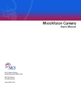
1)
2)
Select the
icon from Control Panel.
At the first page in the Add New Hardware Wizard......
click on the Next> button.
RGA for Windows Manual
SP104001 Rev 2.50
Page 27
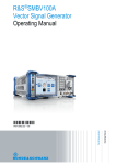
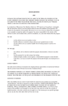
3)
At the second page, select ‘No’ to the question ‘Do you want
Windows to search for your new hardware?’
and then select Next>.
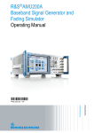
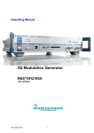
4)
At the third page, select Ports (COM & LPT)
RGA for Windows Manual
SP104001 Rev 2.50
Page 28
as the type of hardware to install, and then click on the Next> button.
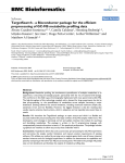
5)
At the fourth page, select (Standard port types) for the Manufacturer
and Communications Port for the Model
RGA for Windows Manual
SP104001 Rev 2.50
Page 29
and then select Next>.
5)
At the fifth page Windows will come up with some likely
hardware settings for the new port, these will most likely be
wrong but at this stage they cannot be changed.
Just select Next> to accept the settings.
6)
At the sixth and final page...
RGA for Windows Manual
SP104001 Rev 2.50
Page 30
click on the Finish button.
7)
You will see the following message;
Select No so that the machine does not re-boot.
Repeat the above steps for each comm. port that you want to add.
Once all the ports are added, all that remains is to configure the correct
settings.
1)
Select the
RGA for Windows Manual
SP104001 Rev 2.50
icon from Control Panel
Page 31
2)
Select the Device Manager tab at the top of the window and then
expand the Ports (COM & LPT) branch by clicking on the + sign....
For each comm. port that you added in the previous steps, select it and carry
out the following steps.
4)
Click on the Properties button and select the Resources tab at the top of
the window...
RGA for Windows Manual
SP104001 Rev 2.50
Page 32
5)
Change the Setting based on: setting to ‘Basic configuration 8’. Once
this is done you will be able to change the Input/Output Range (Base
address) and Interrupt Request (IRQ) settings by double clicking them
and selecting the appropriate values for the configuration of your
comms card.
RGA for Windows Manual
SP104001 Rev 2.50
Page 33
RGA for Windows Manual
SP104001 Rev 2.50
Page 34
6)
When the settings are correct, click the OK button. The following
message will appear :
7)
If you still have more ports to configure then choose No and repeat the
steps above. If it is the last port left to configure then you can select
Yes and the machine will shut down.
As long as the settings on the card match the settings that you have entered,
when you reboot the ports will work OK.
Step 4
Installing the software on the PC.
To install Multi RGA for Windows:
1
Run up Windows 95
2
Insert the program Disk 1 in drive A (or B if you prefer).
3
Click on the Start button on the Taskbar and select Run... from the start
menu.
4
Type a:install (or b:install if you are using the drive B)
The Spectra Install window will be displayed.
The install options:
RGA for Windows
Download
Recall
DDE Examples
Macro Examples
RGA for Windows Manual
SP104001 Rev 2.50
Page 35
will be displayed. You can select the product options by checking the
appropriate products. We strongly recommend you to install all the product
options.
You may also change the default directory where RGA for Windows will be
installed. For the purposes of this manual we will assume you use the default
C:\SPECTRA directory.
5
Click on the Install button to begin the installation process. You will be
prompted to insert program Disk 2 and Disk 3 at the appropriate time.
6
RGA for Windows will be installed on your hard disk and the Spectra
folder will be created which will contain all the RGA for Windows
program items.
7
When the installation process has been completed the configuration
warning box will then be displayed and you will be prompted to run the
Configure program. Press the Ok button.
Step 5
Assigning logical names to the ports on the comms card.
To assign the logical names to each port:
click on the Ports item in the Spectra folder
A warning box will be displayed asking you if you want to install our own
comms. driver, click on the Yes button. See INI File Settings for more
information about the comms driver.
click on the 1 Comms Card Default button (this was the way we configured
the comms card in step 1)
then click on the Ok button.
You will then be prompted to re-start Windows, click on the Yes button to
do this.
Step 5
Configuring RGA for Windows so that each head number is allocated to a
port by its logical name.
RGA for Windows Manual
SP104001 Rev 2.50
Page 36
Click on the Configure item in the Spectra folder, the Configure window will
be displayed. Select the number of heads by clicking on the Number of
Heads connected: dropdown list box then click on the appropriate number in
the dropdown list. Then select the number of comms cards fitted in your PC
by clicking on the Number of Comms Cards fitted: dropdown list box then
click on the number in the list. Then, click on the Ok button.
You should have now successfully installed Multi RGA for Windows.
Further information about the installation process can be found in the rest of
this section.
3.15. Multi-Headed Detailed Installation
This section of the manual gives more detailed information on the
installation of multi-headed RGA for Windows systems. This section will
only be necessary if the step by step guide in the previous section was not
suitable for your system.
3.15.1. Instrument architecture
The complete Multi Headed RGA for Windows system comprises of one PC
running Multi RGA for Windows software and a number of RGA heads.
Each RGA head has three basic elements:
the analyser
this is the part which fits into the vacuum chamber
RF power supply
this is a small electronic unit which fits directly onto
the analyser
control unit
an electronic unit containing the power supplies and
data acquisition system which connects to the PC via a
serial cable
A three headed system would consist of; one PC fitted with a comms card
which is running Multi RGA for Windows, three analysers, three RF power
supplies, three control units and three RS232 serial cables.
Multi headed RGA for Windows systems may be configured to run one
head, this is often done when additional heads are to be added at a later date.
The type of control unit used in RGA for Windows systems may vary.
Microvision combines the traditional control unit and RF power supply
RGA for Windows Manual
SP104001 Rev 2.50
Page 37
electronics into one extremely compact unit which plugs directly onto the
analyser.
Microvision Plus is similar to the Microvision but enhanced electronics
gives improvements in performance and allows additional RGA for
Windows features to be used.
The Satellite is designed specifically to operate with a PC and has no built-in
data display just six LEDs on the front panel to give status indication.
The Vacscan Plus instrument has a built-in CRT and can operate as a stand
alone RGA without being connected to a PC. When the Vacscan Plus is run
from the PC under RGA for Windows it operates in a Satellite emulation
mode and its screen display will mimic the six LEDs on the front panel of
the Satellite. When the Vacscan Plus is first powered up it assumes its stand
alone mode, only when it is connected to the PC via its RS232 port and
RGA for Windows is booted up will it switch to the Satellite emulation
mode.
Vacscan control units may also be used in RGA for Windows systems.
There are certain limitations when using a Vacscan Plus or Vacscan as a
Satellite. These are:
a Remote Vacuum Controller cannot be fitted
an Analogue Output Module is limited to six channels
the scan speeds are slower (approximately 50%)
the Download feature cannot be used
the maximum mass range capability is 200amu
only RS232 serial communication is possible
the RF Tuning and RF Select facilities are not available
A mixture of different types of Spectra control units may be used in multi
headed systems. For instance a three headed system could be made up from
a Satellite, a Vacscan Plus and a Microvision. Any limitations associated
with a control unit would still apply (e.g. you still cannot connect an RVC to
a Vacscan Plus).
3.16. Computer Requirements, Multi
The minimum requirements for running Multi RGA for Windows are listed
in the table below.
This is only the minimum requirement and the overall performance of
Windows and hence RGA for Windows can be improved considerably by
RGA for Windows Manual
SP104001 Rev 2.50
Page 38
increasing the specification of the PC. For this reason we would always
recommend that Multi RGA for Windows is run on a PC fitted with at least a
90 MHz Pentium and 8MB of RAM. A 17inch monitor running at a
resolution of 1024 x 768 is also recommended if data from multiple heads is
to be viewed simultaneously.
Component
Microprocessor
RAM
Hard Disk
Video
Microsoft Windows
Mouse
Serial Port
Description
66MHz 80486sx
8MB
Required with at least 6MB of free space
Standard VGA 640 x 480 16 colour
Version 3.1 or later or Windows 95.
True Type fonts installed.
A mouse is required.
One serial port required to connect each
control unit
to the PC. e.g. four heads four serial ports
3.17. Ports and Addresses
Before describing the Satellite comms card it is worth explaining a little
about the physical address of a port and its logical name.
Each port is identified by a unique base address and an IRQ number which
can be “shared” between ports. This information constitutes the physical
address of a port and is configured on our Satellite Comms Card by setting
jumpers. The possible settings for base address and IRQ selection are listed
in tables 4, 5 and 6.
Logical names take the form of COM1, COM2 etc. and are used by the PC
as a short hand to refer to a physical address (base address and IRQ). In the
IBM PC and compatible computers a traditional relationship exists for
COM1 to COM4 which is listed in table 3. The relationship is not physically
fixed and it is quite possible to change the physical address allocated to any
of these logical names using software. In fact the ports program supplied
with RGA for Windows allows you to do this and assign logical names to
the 4 extra ports on our comms card.
RGA for Windows Manual
SP104001 Rev 2.50
Page 39
Port
Com 1
Com 2
Com 3
Com 4
Address
03F8h to 03FFh
02F8h to 02FFh
03E8h to 03EFh
02E8h to 02EFh
IRQ
4
3
4
3
3.18. Satellite Comms Card
The Satellite communications card (comms card) has been designed to
enable Spectra RGA control units to be connected to a PC for multi headed
RGA applications. If you are installing a multi headed RGA for Windows
system you will almost certainly need to fit a comms card in your PC.
The majority of PCs have two built in serial ports, Com1 and Com2. Com1
is usually used to connect a mouse leaving Com2 free to connect an RGA
control unit in single headed RGA for Windows systems. If both Com1 and
Com2 were being used a comms card would have to be fitted to run a single
head.
In two headed systems the control units will usually be connected to a
comms card leaving Com1 for the mouse and Com2 free. If a bus mouse is
used then it is possible to connect the two control units to Com1 and Com2
and not fit a comms card.
3.18.1. Comms card description
The Satellite comms card is a flexible serial interface board which may be
set up in various configurations depending on the application. It should be
supplied correctly configured for your application but before fitting the card
it is worth checking the configuration. All the necessary information for
configuring the card is given in the following section.
The Satellite comms card is populated according to the number of ports
requested, one port is required for each control unit with four ports being
available on a fully populated card. To determine how many ports are fitted
look to see how many of the large 40 pin ICs (IC1, IC7, IC13, IC16) are
fitted one is required for each port. Also check that these ICs carry the
identification PC16550DN or similar (only the numbers 16550 are
important).
The Satellite comms card will have been set to the requested serial interface
specification, RS232 or RS422. To check this, for RS422 IC5, IC9 and IC11
RGA for Windows Manual
SP104001 Rev 2.50
Page 40
will not be fitted and links Lk1 to LK8 will be fitted otherwise the board will
be configured for RS232.
Also note the position of the connectors for the four ports on the comms
card:
Port 1
Port 2
Port 3
Port 4
PLG 5 mounted on the PCB closest to the edge connector
PLG 4 mounted on the PCB furthest from the edge connector
fitted to a flying lead connected to PLG 6 on the PCB
fitted to a flying lead connected to PLG 2 on the PCB
3.18.2. Setting the physical address
The Physical Address is set by the three jumpers J8, J9 and J13. You should
check against the following tables to ensure the required configuration is
obtained.
Four setting options are available for the address decoding of the four ports.
Jumper J9 is used to select the required option:
J9
no link
3-4
1-2
1-2&3-4
PORT 1
03F8
0280
02A0
03E8
PORT2
02F8
0288
02A8
02E8
PORT 3
03E8
0290
02B0
02A0
PORT 4
02E8
0298
02B8
02A8
Note that there are 8 bytes per port.
Each of the four ports generates its own IRQ (interrupt request). Under
normal circumstances the four IRQs are “ORed” together and connected to a
single IRQ line. Jumper J8 sets which IRQ line is selected. The table below
shows the various options:
J8
1-2
3-4
5-6
7-8
9 - 10
IRQ
IRQ 3
IRQ 4
IRQ 5
IRQ 7
IRQ 2
The IRQ setting for Port 1 has the additional capability of connection to IRQ
RGA for Windows Manual
SP104001 Rev 2.50
Page 41
4 or to the same IRQ as the other ports. This is governed by the setting of
jumper J13:
J13
1-2
2-3
IRQ
same as ports 2,3 and 4
IRQ 4
Jumpers: J1, J2, J3, J4, J5, J6, J7, J10, J11, J12, J14 & J15 control the
handshaking lines for the various ports. The setting of these links should not
be altered.
3.18.3. Choosing the configuration
The configuration you choose will depend on your PC as well as the number
and type of peripheral devices you have connected. The two important
things to note are:
you will have to allocate a Comms Port for each RGA control unit you want
to connect
you need one IRQ for all the RGA control units connected (regardless of the
number) but no other devices must use this IRQ.
The majority of PCs have two built in serial ports usually referred to as Com
1 and Com 2 and use addresses 03F8-03FF and 02F8-02FF respectively. The
interrupt request lines used for Com 1 and Com 2 are IRQ4 and IRQ3
respectively.
Great care should be taken when selecting port numbers (Com1 to Com12)
and IRQ lines since their use may vary from one type of “compatible” PC to
another. Before fitting a comms card or attempting to install RGA for
Windows you should be familiar with the configuration of your PC.
Our standard configuration for the Satellite comms card is:
J9
Port 1
Port 2
Port 3
Port 4
link 3 to 4
address
address
address
address
RGA for Windows Manual
SP104001 Rev 2.50
which sets
0280 to 0287
0288 to 028F
0290 to 0297
0298 to 029F
Page 42
J13
link 1 to 2
which sets
Port 1 to the same IRQ as Ports 2 to 4
J8
link 5 to 6
which selects
IRQ 5 for the four Ports.
Unless you specified otherwise your comms card will have been supplied
with the above configuration.
The comms card should be installed in accordance with the PC
manufacturers instructions for the installation of plug-in cards. Note that you
will need TWO free slots for each comms card.
3.19. Connecting Control Units
Multi RGA for Windows software will run from one to eight control units,
split into two groups of four units. The control units will normally be
connected to Ports 1 through 4 on one of up to two Satellite comms cards,
depending on the number of heads being used. The connections between
your PC and the control units are made using the serial cables supplied,
usually these will be RS232. The standard cable to connect a Satellite or
Microvision to the PC is a 9-way D plug to 9-way D socket RS232 cable, a
25-way D socket to 9-way D plug RS232 cable is available as an option. To
connect a Vacscan or Vacscan Plus to the PC a null modem cable is required
as standard this is a 9-way D socket to 9-way D socket. A 25-way D socket
to 9-way D socket is available as an option. In all cases the standard cable
length is 3 metres (9 feet) longer cables are available on request, please
contact your local Spectra facility.
Other types of serial communication such as RS422 or RS485 may be
possible depending on the types of control units being used. Please refer
RS422 and RS485 if you are using RS422 or RS485.
CAUTION
You must only use RS232 cables supplied with the equipment. We
cannot guarantee that other manufacturers cables will work correctly in
Spectra RGA systems.
If you must use an RS232 cable not supplied with the equipment then use
the cable supplied as an extension to your cable ENSURING THE CABLE
SUPPLIED WITH THE EQUIPMENT IS PLUGGED INTO THE PC.
RGA for Windows Manual
SP104001 Rev 2.50
Page 43
Identify the serial port to which you will connect the first control unit. It is
worth making a note of which control unit is connected to which port, for
example Head 1 to Port 1. Then, connect the remaining control units.
Note, that it is only necessary to have the control units connected to the PC
to run RGA for Windows, you do not have to have the RF power supply or
analyser connected at this stage. In the case of Microvision and Microvision
Plus, the unit does not have to be connected to the analyser. However, if you
enter one of the scanning modes an RF Failed message will be generated.
As part of the installation process the configuration program will be run.
This will determine which serial ports are available on your PC and ask you
to specify which one is connected to each control unit.
3.20. Installing Share, Multi
If you are installing RGA for Windows to run under Windows 3.1 you will
need to install SHARE. If you are installing RGA for Windows on later
versions of Windows, such as Windows for Workgroups 3.11 or Windows
95, you will not need to install SHARE, so you may skip this section.
The SHARE program is supplied with DOS and allows different programs to
use common files in an orderly fashion. RGA for Windows will not run
without this command as the Microsoft Access Database Engine is used by
RGA for Windows for the spectra library. The library data files are written
in an Access format. You should find SHARE.EXE in your DOS subdirectory.
To install the share command add the following line to your autoexec.bat file
in a part of the file that is used when booting Windows:
c:\dos\share.exe /l:500 /f:5100
This assumes that the share.exe command is in the DOS sub-directory
c:\dos. If it is in another sub-directory use that name instead of dos in the
above line.
note that there is a single space before each of the two forward slashes (/).
f:
l:
allocates the number of bytes for the share file information
sets the number of files that can be locked at any one time.
When the line has been added to the autoexec.bat file you need to re-boot
RGA for Windows Manual
SP104001 Rev 2.50
Page 44
your PC. Do not re-boot your PC until you have read the next section.
3.21. Installing Override.com
If you are running under Windows 95 you do not need override.com.
In multi headed RGA for Windows systems where a Satellite comms. card is
being fitted it is necessary to add the line c:\spectra\override.com to the
autoexec.bat file. This is because the system BIOS on most PCs contains the
addresses of the first four Com ports. When you boot up your PC the system
BIOS looks for these Com port addresses and if they are present uses them
to over write those in the Windows system.ini file. To prevent this the
override.com program writes zeros into the BIOS for the four Com port
addresses so that they are ignored when the PC is booted up and the values
from the system.ini file are used.
To add the line:
1.
Open a text editor such as Write which can be found in the Accessories
program group in Windows.
2.
Open the autoexec.bat file which can be found in the root directory,
usually c:\.
3.
Add the line c:\spectra\override.com to a part of the autoexec.bat file
which is used when Windows is booted up.
4.
Save the autoexec.bat file under the same name.
5.
Now re-boot your PC so that the change is implemented.
Note: since the content of autoexec.bat files vary greatly from computer to
computer it is not possible define exactly where the line should be put.
Usually it will be towards the end of the file. If you experience any
difficulties try putting the extra line in a different place in the autoexec.bat
file.
3.22. Comms Cards and Windows 95
If you are running under Windows 95 and are installing a comms card you
will need to configure Windows 95 to recognise the card. There is no
RGA for Windows Manual
SP104001 Rev 2.50
Page 45
software to automatically do this. Please follow the step by step instructions
in Quick Guide Windows 95 . You should do this before you install the
RGA for Windows software.
3.23. Running Install, Multi
The INSTALL.EXE program included on program Disk 1 should be used to
install Multi RGA for Windows onto your hard disk. To install RGA for
Windows follow the procedure listed below:1
Run up Windows
2
Insert the program Disk 1 in drive A (or B if you prefer).
3
Chose the Run... option from the Windows Program Manager File
select menu.
Win95 Click on the Start button on the Taskbar and select Run . . .
4
Type a:install (or b:install if you are using the drive B)
The Spectra Install window will be displayed.
The install options:
RGA for Windows
Download
Recall
DDE Examples
Macro Examples
will be displayed. You can select the product options by checking the
appropriate products. We strongly recommend you to install all
the product options.
You may also change the default directory where RGA for Windows will be
installed. For the purposes of this manual we will assume you use the default
C:\SPECTRA directory.
5
Click on the Install button to begin the installation process. You will be
prompted to insert program Disk 2 and Disk 3 at the appropriate time.
RGA for Windows Manual
SP104001 Rev 2.50
Page 46
RGA for Windows will be installed on your hard disk and a program group
called SPECTRA will be created and the Multi RGA for Windows program
items added.
Win95
RGA for Windows will be installed on your hard disk and the
Spectra folder will be created which will contain all the RGA
for Windows program items.
When the installation process has been completed the Share.exe warning box
may be displayed; click on the Ok button. The
configuration warning box will then be displayed and you will be prompted
to run the Configure program. Click on the Ok button.
3.24. Spectra Program Group, Multi
The Spectra program group as shown below contains seventeen program
items, each is briefly described below.
Win95
The items in the Spectra folder are described below, they are
the same as the program items in the Spectra program group in
Windows 3.1 and later systems. To display the Spectra folder click on the
Start button on the Taskbar and select Programs | Spectra from the start
menu.
RGA for Windows Manual
SP104001 Rev 2.50
Page 47
RGA Multiplex
This item is used to start RGA for Windows using the
Multiplex facility and the previous session parameters.
RGA Multiplex Reset
This item is used to start RGA for Windows using the
Multiplex facility and the default parameters.
Group 1
This item is used to start the first group of up to four heads
using the settings from the previous session.
Group 1 Reset
This item is used to start the first group of up to four heads
using the default settings.
Group 2
This item is used to start the second group of heads (heads
5 to 8) using the settings from the previous session.
Group 2 Reset
Used to start the second group of four heads using the
default settings.
Configure
This runs the configure program allowing the selection of
the comms ports.
Ports
This is a utility program allowing custom configuration of
multiple comms ports. It is designed primarily for multi
headed systems where Spectra Satellite comms cards are
being used.
RGA Help
The help files are contained in a separate program and may
be opened by double clicking this icon, pressing the help
button or selecting Help whilst running RGA for Windows.
Uninstall
This utility is used to remove RGA for Windows from your
hard drive.
DDE Test
This test program is used with the DDE Links feature and
is described in section 5.
RGA for Windows Manual
SP104001 Rev 2.50
Page 48
Download
This is used to upgrade the code in a Satellite control unit,
refer to Download for more information.
Recall
Recall is a separate program which allows the review of
RGA for Windows data files obtained using the Disk Store
feature described in Disk Store . Please refer to the Recall
manual.
Recall Help
Recall has its own help files stored as a separate program,
again refer to the Recall manual.
DDE Examples
These are example files to help the user with the DDE
(dynamic data exchange) Links feature. Please refer to
section 5 of this manual.
Macro Examples
These are example files to help users with the Macro
feature described in section 5 of this manual.
To complete the installation of Multi RGA for Windows you must run the
configuration program. To do this double click on the Configure icon in the
SPECTRA program group.
3.25. Configuring Multi RGA for Windows
The configuration program should be run as part of the installation process
and can be re-run at any time to change the configuration of Multi RGA for
Windows. To run Configure, double click the Configure icon in the
SPECTRA program group.
Win95
To run Configure click on the Start button on the Taskbar
and select Programs | Spectra and click on the Configure
item in the Spectra folder, the Configure window will be
displayed.
The Configure Window will be displayed, as shown below.
RGA for Windows Manual
SP104001 Rev 2.50
Page 49
The first thing to set is the number of heads which are connected to the PC.
To do this click on the down arrow to the right of the Number of Heads
connected: text. A dropdown list containing the numbers 1 to 8 will be
displayed, click on the appropriate number.
Next select the number of Satellite comms cards which are fitted in the PC.
Click on the down arrow to the right of the Number of Comms cards
fitted: text. Click on the appropriate number in the dropdown list. Note that
0 is selected when a comms card is not fitted and the two built-in comms
ports Com1 and Com2 are to be used.
Now you should choose whether you wish to carryout a standard or custom
configuration. The standard configuration will use our default settings for
the assignment of; heads to ports, addresses to ports and IRQ settings. These
default values will work successfully on the majority of computers and the
various settings are given at the end of this section. The custom
configuration allows the user full control of the set up of RGA for Windows.
We recommend using the standard configuration if at all possible.
To select the standard configuration click on the Standard configuration
radio button and then click on the Ok button.
To select the custom configuration click the Custom configuration radio
button and then click on the Ok button. The custom configuration window
will be displayed, as shown below, which lists the nine possible comms
ports with those not available being grayed out. For example Com1 will
RGA for Windows Manual
SP104001 Rev 2.50
Page 50
often be grayed out because the mouse is connected to Com1. Each of the
available Comm ports can be assigned to a group, either group 1 for the first
four heads or group 2 for heads 5 to 8. Also, each of the four heads within a
group may be assigned to a particular Comm port. To do this click on the
appropriate down arrow and select the required number from the dropdown
list by clicking on it.
From the custom configure window you can select the ports window by
clicking on the Ports button. This has the same effect as selecting the Ports
icon from the Spectra program group. The ports window will be displayed as
shown below.This shows base address and IRQ for each of the nine possible
comms ports which may be set-up to match the hardware fitted to your PC.
Three default options are available through the three buttons No Comms
Card Default, 1 Comms Card Default and 2 Comms Cards Default.
These give the most common configurations. As you click on each of the
buttons the values for the base address and IRQ will change. Selecting one
of these three buttons gives the same result as selecting 0, 1 or 2 comms
cards in the configuration window. The default settings are given at the end
of this section.
RGA for Windows Manual
SP104001 Rev 2.50
Page 51
Once you have made the changes click the Ok button and the restart
Windows warning box will be displayed. Click the Yes button and Windows
will be re-started to implement the new settings.
When Windows has re-started you must enter the configuration program
again, whether you are performing a standard or custom configuration and
repeat the configuration process outline above re-setting any parameters that
are not as you set them. This time when you exit the configuration program
Windows will not be re-started.
You have now completed the installation of the RGA for Windows software.
We strongly recommend that you now work through the Getting started
section of this manual. This will not only introduce you to RGA for
Windows but will also check out the operation for your RGA system.
3.26. RS422 and RS485
RS422 is a differential serial communications system usually used when the
distance between the transmitter and receiver exceeds that permitted under
RS232. If you are using a Satellite control unit it must be fitted with the
RS422 option The Satellite comms card must be configured for RS422
RGA for Windows Manual
SP104001 Rev 2.50
Page 52
operation. The cables used are not the same as the RS232 cables and the two
types are not interchangeable. Using RS422 makes no difference to the
software as the serial protocol is the same. Connection of the system is the
same as RS232 systems.
At the time of writing none of the Spectra range of control units support
RS485, although it is planned to be offered in the future. The Satellite
comms card does not support RS485.
3.27. Windows System Ini File
The windows system.ini file contains the line
comm.drv = comm.drv
during the installation process our own comms port driver is loaded on to
your computer to allow serial communications with more than four
peripherals (the limit in Windows). The above line will be replaced with the
line:
comm.drv = c:\spectra\ledacomm.drv
assuming you use the default directory.
3.28. Default Comms Settings
No Comms Cards Fitted
Port
Built In 1
Built In 2
None
None
None
None
None
None
None
Com
1
2
3
4
5
6
7
8
9
Group
1
1
None
None
None
None
None
None
None
Head
1
2
None
None
None
None
None
None
None
Base Address
03F8
02F8
Off
Off
Off
Off
Off
Off
Off
IRQ
4
3
Off
Off
Off
Off
Off
Off
Off
This is used when one or both of the built-in comms ports are to be used.
RGA for Windows Manual
SP104001 Rev 2.50
Page 53
Note if no comms card is selected and the mouse is connected to COM1
only COM2 will be shown as available to RGA for Windows.
3.28.1. One Comms Card Fitted
Port
Built In 1
Built In 2
Comms Card 1
Comms Card 2
Comms Card 3
Comms Card 4
None
None
None
Com
1
2
3
4
5
6
7
8
9
Group
None
None
1
1
1
1
None
None
None
Head
None
None
1
2
3
4
None
None
None
Base Address
03F8
02F8
0280
0288
0290
0298
Off
Off
Off
IRQ
4
3
5
5
5
5
Off
Off
Off
3.28.2. Two Comms Cards Fitted
Port
Built In 1
Built In 2
1st Comms Card 1
1st Comms Card 2
1st Comms Card 3
1st Comms Card 4
2nd Comms Card 1
2nd Comms Card 2
2nd Comms Card 3
2nd Comms Card 4
Com
1
None
2
3
4
5
6
7
8
9
Group
None
None
1
1
1
1
2
2
2
2
Head Base Address
None
03F8
None
02F8
1
0280
2
0288
3
0290
4
0298
1
02A0
2
02A8
3
02B0
4
02B8
IRQ
4
3
5
5
5
5
5
5
5
5
3.29. Upgrading From Earlier Versions
3.29.1. RS232 cable
Users who are upgrading from earlier versions of RGA for Windows
software may need to modify the RS232 cable. If you encounter either of the
following error messages:
"Noise has been detected on the Carrier Detect line of the RS232 interface
RGA for Windows Manual
SP104001 Rev 2.50
Page 54
which may degrade the performance of your system. Refer to the trouble
shooting section of the RGA for Windows manual."
OR
"Noise has been detected on the Ring Indicator line of the RS232 interface
which may degrade the performance of your system. Refer to the trouble
shooting section of the RGA for Windows manual."
then you definitely need to modify the cable.
WARNING
This work must only be carried out by a competent person. If in any
doubt, contact your local agent for a replacement cable.
To do this:1.
Switch off both the PC and the Satellite control unit and disconnect the
power supply leads.
2.
Unplug the RS232 cable from the PC.
3.
Carefully remove the D-type connector shell. This may involve prizing
apart the two halves in the case of a plastic shell or removing the two
screws in the case of a metallised shell.
4.
Disconnect the wire connected to pin 1 of the 9 way D socket (pin 8 in
the case of a 25 way D socket). Carefully cut back this wire to ensure it
cannot short on any of the other pins, the cable braid or the metal shell.
5.
Connect pins 1,9 and 4 together (9 way) or connect pins 2,8 and 20
together (25 way). Note that pin 4 (9 way); pin 20 (25 way) already has
a wire connected - keep this connection.
6.
Re-assemble the D-type connector.
7.
Re-connect the serial cable and then the mains leads.
8.
Switch on the control unit and run up the PC.
9.
Run RGA for Windows using RGA Reset.
RGA for Windows Manual
SP104001 Rev 2.50
Page 55
Remember the above should only be necessary if you are upgrading from
earlier versions of RGA for Windows. New instruments supplied with
version 2.00 or later versions of software should have a modified RS232
cable.
3.29.2. Preserving settings
The installation procedure has been improved from previous versions so that
if a copy of RGA for Windows is already on the computer in the same
directory that you choose to install the new version to it will not overwrite
any settings from the original installation. All the settings are stored in a file
called RGA4WIN.INI (RGA4WINn.INI for Multi RGA for Windows where
n is the head number) you may wish to save a copy of this in a separate
directory before you start the upgrade. Any changes that are required to
upgrade the original settings files to V2.40 format will be made and a
message indicating that the upgrade was carried out will be displayed.
If an upgrade was not carried out or it failed for some reason then the normal
configuration procedure is entered.
3.30. Download
Download may only be used with Satellite, Microvision and Microvision
Plus units. It CANNOT be used with Vacscan and Vacscan Plus units.
The RGA control unit has EPROM based software and an area of battery
backed RAM which can also contain the control unit operating software.
When RGA for Windows establishes communication with the Satellite,
Microvision or Microvision Plus the code held in the battery backed RAM
will be used if it is found, otherwise the EPROM software is used.
When a software upgrade is carried out it is often necessary to upgrade the
software in the control unit as well as the RGA for Windows software on the
PC. The control unit software can be downloaded from the PC via the serial
link thus removing the need to change the EPROM.
To do this:
double click on the Download icon in the Spectra program group. The
Download dialog box will be displayed as shown below.
Win95
To run Download click on the Start button on the Taskbar and
RGA for Windows Manual
SP104001 Rev 2.50
Page 56
select Programs | Spectra and click on the Download item in
the Spectra folder, the Download window will be displayed as
shown below.
Select the comm. port by clicking on the Comm port: dropdown list box
and then click on the required comm. port. As soon as you do this the RGA
for Windows software will try to establish communications with the control
unit. If this is successful one or more lines of information will appear in the
Instrument Information: box. This process can be repeated by clicking on
the Re-read info button and will be repeated each time a new comm. port is
selected.
To load the control unit code into RAM click on the Load Program button
and the Select File To Download dialog box will be displayed. You can
select the drive and directory where the code is stored. Also you can select
the file type as Satellite and Microvision/Microvision Plus control units have
different file types. The full file name for Satellite code to run RGA for
Windows using the default path is:
C:\spectra\satcode.ram
RGA for Windows Manual
SP104001 Rev 2.50
Page 57
The full file name for Microvision code to run RGA for Windows using the
default path is:
C:\spectra\microv.img
The full file name for Microvision Plus code to run RGA for Windows using
the default path is:
C:\spectra\mvplus.img
Once the correct file name has been specified click on the OK button and the
code will be transferred, this takes a little time (just long enough to get a cup
of coffee, if you’re quick).
Click on the Exit button to close the Download dialog box.
Clicking on the About button will display the Download version window
which provides useful information for our technical staff should you require
assistance.
Note that in a multi-headed system it will be necessary to Download control
unit code to each control unit in the system. The above procedure must be
repeated selecting each comm. port used in turn.
To remove the software from the battery backed RAM in the control unit use
the Unload button. The RGA control unit will revert to using the software
held in the EPROM. This must be done if the EPROM in a Satellite has been
changed, otherwise RGA for Windows will carry on using (or trying to use)
the code held in the battery back RAM.
It may not always be possible to upgrade the software in the Satellite by
using the download facility. For instance if the EPROM software is many
software versions older than the new software. Please contact your local
Spectra facility if you are in doubt. Changing the EPROM is quite straight
forward and if it is required full instructions will be supplied with the
replacement EPROM.
If you are upgrading to version 2.40 RGA for Windows from version 2.1x
(where x = 0 to 9) you will need to upgrade the software in the Satellite
control unit but this can be done using the Satellite Download facility.
RGA for Windows Manual
SP104001 Rev 2.50
Page 58
Remember that you cannot use the Satellite Download facility with Vacscan
Plus or Vacscan control units. To upgrade to version 2.40 from earlier
versions you will have to change the EPROM(s) in the control unit. This is a
straight forward procedure, please contact your local Spectra service centre
for further details.
3.31. Baking The Analyser
CAUTION
The Electron Multiplier (SEM) MUST NOT be operated at
temperatures above 50oC.
With dual (faraday and electron multiplier) detector instruments serious
damage will be caused to the electron multiplier if it is operated at
temperatures above 50oC. Where instruments use a standard RF power
supply the RF must be removed to bake out so there is no chance of the
multiplier inadvertently being switched on.
It is possible to run instruments using RF power supplies fitted with a
bakeable adapter during a bake out. In this case only the faraday detector
should be used NOT the multiplier.
No damage is caused to the multiplier by high temperatures provided it is
not switched on.
The only remedy when a multiplier has been damaged due to being operated
at higher temperatures is to replace it.
RGA for Windows Manual
SP104001 Rev 2.50
Page 59
This page is deliberately left blank.
RGA for Windows Manual
SP104001 Rev 2.50
Page 60
Section 4.
Getting Started
4.1. Getting Started Introduction
This manual assumes that you are familiar with the Windows environment.
We have made every effort to use the standard windows terminology so that
you can quickly refer to the Microsoft Windows manual for detailed
information about specific windows topics. In addition to the standard
Windows terminology, some terms are defined which describe controls and
concepts used within RGA for Windows. The basic operation of RGA for
Windows and its terminology are introduced in this section.
Also included in this section is a quick general introduction to the subject of
Residual Gas Analysis. The modes of operation and techniques employed
within the RGA for Windows package are also introduced.
At the end of this section we include a guided tour of RGA for Windows.
We strongly recommend that you take the time to run through the tour since
it will give you a basic understanding of how to use RGA for Windows and
will check that the complete system is operating correctly.
RGA for Windows Basics
Parts of RGA for Windows
Controls
Quadrupole RGA
Guided Tour
Running RGA for Windows
Running Diagnostics
Setting a Total Pressure Trip
Starting the Bar Chart Mode
Switching a Filament On
Changing the Mass Scan
4.2. RGA for Windows Basics
4.2.1. Running RGA for Windows
After installing RGA for Windows, thirteen (seventeen in the case of Multi
RGA for Windows Manual
SP104001 Rev 2.50
Page 61
RGA for Windows) program items will have been added to the SPECTRA
program group as shown in figures 1 and 2.
Win95
The RGA for Windows items appear in the Spectra folder.
Click on the Start button on the Taskbar then select
Programs | Spectra.
The configure program was run as part of the installation process. If you
ever connect control units to different serial (Com) ports, the configure
program must be run to specify the serial port used.
When RGA for Windows is run for the first time after installation, a
POWER UP RESET should be performed. This will ensure that all the
parameters stored in data files on the PC and in the control unit's memory
are reset to the default values. To perform a POWER UP RESET double
click the RGA Reset program item icon.
Win95
Click on the Start button on the Taskbar, select Programs |
Spectra then click on the RGA Reset item.
If you are using Multi RGA for Windows double click on the RGA
Multiplexer Reset program item icon, do not use the Group 1 Reset and
Group 2 Reset icons until you are more familiar with the system.
Win95
If you are using Multi RGA for Windows click on the RGA
Multiplexer Reset item, do not use Group 1 Reset and Group
2 Reset until you are more familiar with the system.
To run RGA for Windows when a POWER UP RESET is not required you
should double click the RGA program item icon.
Win95
Click on the Start button on the Taskbar, select Programs |
Spectra then click on the RGA item.
To run Multi RGA for Windows when a POWER UP RESET is not required
you should double click on the RGA Multiplexer program item icon.
Win95
Click on the Start button on the Taskbar, select Programs |
Spectra then click on the RGA Multiplexer item.
Mouse and keyboard operation
RGA for Windows Manual
SP104001 Rev 2.50
Page 62
RGA for Windows operation is similar to any other windows application.
Keyboard operation is supported using the standard menu and shortcut keys.
There are a number of operations which can be performed more efficiently
using the keyboard, however a keyboard is only required if you want to
specify a filename for disk store. Text information can only be entered using
the keyboard and you will probably find that changing the numeric value of
a parameter by a large amount is best achieved by entering the new value
from the keyboard.
The basic techniques for keyboard and mouse operation are described in the
Microsoft Windows user guide.
4.3. Parts of RGA for Windows
A typical peak jump mode display is shown below click on the the graphic
to identify the various parts of the screen.
Title Bar
The Title Bar unsurprisingly contains the application name RGA for
RGA for Windows Manual
SP104001 Rev 2.50
Page 63
Windows, the head number and the currently selected mode.
Menu Bar
In common with other Windows applications all the software functions can
be accessed from the menu bar.
Icon Bar
Buttons on the icon bar allow access to the main functions and modes within
RGA for Windows.
Setting Bar
Functions and parameters which are related to a specific scanning mode are
displayed and altered here.
Channel Buttons
Modes which are channel based (peak jump, multi trend and fast scan) have
a number of parameters associated with each channel. These parameters are
altered in the Channel Settings dialog boxes which are accessed using the
channel buttons.
Help Bar
To discover the purpose of a particular button, you should point to the button
of interest. The text displayed on the help bar will automatically change to
indicate the function of that button. The text displayed will only be updated
when you point to another button.
Mode Window
The scanning modes plot the results of the scan in this window.
4.4. Controls
Controls on the icon and setting bars together with those available through
the channel buttons provide the ability to set most of the parameters and
select the main functions. There are some more advanced features which can
only be set from the menu bar. Most of the controls on the icon and setting
bars and in the channel buttons are interactive allowing you to quickly
change a parameter or select a function. In some cases the controls will
cause a dialog box to be displayed allowing a series of parameters to be set
using standard windows controls. A description of each dialog box is
included in the reference section of this manual. The basic operation of the
interactive controls are explained below.
RGA for Windows Manual
SP104001 Rev 2.50
Page 64
On/Off Buttons
These are controls which have two states. When you click on the button the
state of the parameter is toggled and the button will indicate the new state of
the parameter. On/off buttons can appear on the icon or the setting bar
where the current state is indicated by the simulated raised or depressed state
of the button. When the button is raised the function is off and when
depressed it is on. The leak check audio on/off and bar chart autorange
buttons use this type of control.
Push button
These buttons depress while you click but will then spring out and activate
the required function straight away. Parameter increment and decrement
buttons operate in this way. Some push buttons have an auto repeat feature
which enables the button to be "repeatedly pressed" while the mouse button
is held depressed.
Button group
This refers to a group of three related push buttons which appear on the
setting bar in several modes. Although the buttons operate just like any other
push button they are used to set the same parameter. The centre button has
an icon indicating to which parameter the button group relates. If you click
this button a parameter setting dialog box is opened which allows the
parameters value to be set. The button to the left (↑) and right (↓) will
decrement and increment the parameter respectively.
Dropdown list box
Where a parameter may take one of a limited number of possible values a
dropdown list box is used. When you click on the parameter a list of
available settings is displayed. You should then click the required setting as
displayed in the list. In some cases where the list of options is too long a
vertical scroll bar will appear to the right of the list indicating that other
possible settings are available. The range control on the setting bar is an
example of a dropdown list box.
4.5. Quadrupole RGA
Quadrupole residual gas analysers are regularly used to characterise and
monitor vacuum environments at pressures below 1x10⁻⁴ mBar. Operation at
higher pressures is carried out using a quadrupole with a high pressure
adapter. The spectra obtained by plotting ion current against mass can
RGA for Windows Manual
SP104001 Rev 2.50
Page 65
provide the user with valuable information on the relative abundance of
gasses in the vacuum system. RGAs may be used to perform a number of
different types of analysis. Since the demands of different applications vary
widely, it is necessary to provide a range of optimised general purpose
modes of operation. To get the best possible performance from the RGA the
correct mode of operation should be selected for your particular application.
The basic modes of operation supported by RGA for Windows are listed
below along with a brief description of when they should be used.
4.5.1. Vacuum scan
Vacuum scan is a fully automated vacuum analysis program that requires the
minimum effort to produce useful information about the state of your
vacuum system. It will scan a user selected mass range for the largest partial
pressures within a defined magnitude range, as shown below.
When complete, the mass numbers and their magnitudes are listed in
descending order, as shown below. The number of masses reported is
variable between 1 and 12.
RGA for Windows Manual
SP104001 Rev 2.50
Page 66
This mode carries out a basic RGA check and as such should be used
regularly for system monitoring. All too often people forget about the
quality of their vacuum until something goes wrong. With vacuum scan you
can regularly check the vacuum quality and print the results for hard copy
without spending any time on the system yourself.
The mass range to be scanned may be adjusted from 1 to the maximum mass
available on your system. The magnitude range is set in terms of the
instrument gain ranges. If the ranges scanned are set so that the start range is
E-6 and the end range is E-7, the required number of masses with
magnitudes in the range 9.90x10⁻⁶ down to 0.7x10⁻⁷ will be listed.
When the scan has finished and the results have been displayed some
additional functions are available. Firstly the mass numbers and range of the
peaks listed may be transferred to the peak jump, multi-trend and fast scan
modes. Secondly you have the option to ask for a list of suggested common
gasses for the masses present.
The results of the last scan are stored along with a date and time stamp. It is
possible at any time to view the results of the previous vacuum scan until the
mode is run again. At this time the previous results are overwritten with the
new scan results.
RGA for Windows Manual
SP104001 Rev 2.50
Page 67
4.5.2. Analogue
This is not intended to be used as an analytical mode although it may be
useful for some applications. It is an important mode for tuning the R.F.
head and as a means of monitoring the general condition of the analyser.
Under normal operation you should not need to use this mode.
4.5.3. Bar chart
In this mode the peak intensity information is presented in a histogram
format as shown below
The start mass and mass span of the scan can be chosen as can the range on
which the scan is taken. An autorange feature is also available which will
adjust the range of the instrument until the mantissa of the largest peak falls
within the range 0.70 and 9.60 when the linear axis is selected. A
logarithmic intensity axis enables the display of data over the full dynamic
range of the instrument.This mode is used for taking a general over-view of
the vacuum system. It is the mode in which you are likely to find something
unexpected within the vacuum system.
This mode is useful in many circumstances....
RGA for Windows Manual
SP104001 Rev 2.50
Page 68
•
•
•
When you wish to take a snapshot picture of the vacuum system at
any point in time.
If you do not know what is going on in the vacuum system you
would use this mode to see which gas predominates.
If you are collecting data on more than the 12 components which
could be handled by the peak jump or multi-trend modes.
4.5.4. Peak jump
Having established that the general condition of your vacuum system is
satisfactory, your attention will probably turn to a limited number of specific
components on which your process depends. You now no longer need to
spend time measuring every peak in the system but want to concentrate on
just a few.
This mode enables you to individually set the mass in any of the twelve
channels. You can assign each individual channel to either a specific gain
range or, set the instrument to autorange throughout its whole dynamic
range. This gives tremendous flexibility for process monitoring as you can
monitor high and low level components simultaneously. As you are only
RGA for Windows Manual
SP104001 Rev 2.50
Page 69
spending time looking at the chosen peaks this gives you a major time
saving in one of two ways.
Firstly this enables you to take readings more frequently. However, the
instrument offers a variable accuracy code which enables you to control the
measurement routine, the more accurate the result, the longer the time it will
take. This means that instead of using the time in peak jump to acquire more
data, you could acquire the same amount of data but with considerably
improved accuracy.
Secondly, in addition to measuring partial pressure peaks you may select
either total pressure, or one of the two or more (depending on RGA control
unit type) built in analogue inputs to be measured in any channel.
This mode also has a high and low alarm capability for each channel. The
alarms operate in the range 0.1E-14 to 9.9E-05. The alarm condition is
triggered if the magnitude of a peak exceeds the high alarm setting or falls
below the low alarm setting. The peak is plotted in red if its magnitude falls
outside the alarm range and an output is set true on the relevant pin of the
AUX I/O connector on the control unit.
There are a number of key advantages for this mode:The logarithmic axis and auto ranging ability makes this mode useful for any
kind of process monitoring. Alarms enable the system to be used to regulate
key process values.
The increased speed with which data can be collected makes this mode
useful for short term experimental monitoring applications.
The control you have over the accuracy makes this mode useful for detailed
experimental work.
4.5.5. Multi trend
Very often when only a few components are being measured you may not be
interested in the instantaneous magnitude of a particular mass, but rather in
the variation in magnitude over time. The trend mode enables up to twelve
components to be monitored over time. You can individually set the mass,
range and detector for each channel. The results are displayed on an intensity
versus time graph which scrolls across the screen. The scroll rate is set by
the scan interval. The interval sets the resolution of the time axis and also
sets the minimum scan rate. If the time taken to complete a single scan is
RGA for Windows Manual
SP104001 Rev 2.50
Page 70
greater than the interval then the data will be displayed as soon as it is
aquired.
You have the option of a logarithmic intensity scale. This enables you to
display trends over the full dynamic range of the instrument, and is probably
the most widely used mode for general process monitoring.
4.5.6. Leak check
Leak checking is one of the fundamentals of vacuum system testing and
maintenance. It is mainly used to test the vacuum integrity of the chamber in
which the analyser is mounted, using a probe gas, normally helium.
It can also be used as part of a test rig for leak checking vacuum
components.
Any probe gas within the mass range of the instrument can be used with any
range and detector setting. This flexibility enables the leak check mode to be
used as a general purpose, fast scanning single channel trend mode.
The mode offers an audible tone, the frequency of which is proportional to
the peak height. This allows leak checking to be performed when the screen
cannot be seen. An external speaker can be connected to the remote audio
output socket on the RGA control unit for very large systems.
RGA for Windows Manual
SP104001 Rev 2.50
Page 71
4.6. Guided Tour
This section takes you step by step through the initial powering up of the
instrument and will check that the system is operating correctly. It ensures
that the control unit has arrived in good working order, that the analyser is
installed properly in the vacuum chamber and that the link to your PC has
been made.
The step by step guide will introduce you to many of the features available
in RGA for Windows and also provides you with useful background
information about how it operates.
4.6.1. Before you start
Before you can run through the guided tour the various components in the
system must be installed and connected together correctly. You should refer
to the Unpacking and installation section of the RGA control unit manual for
details about installing the analyser and how to connect it to the RGA
control unit. The control unit to PC connection, software installation and
configuration should be completed according to the instructions given in
RGA for Windows Manual
SP104001 Rev 2.50
Page 72
section 2 of this manual.
Before proceeding with the tour you should also ensure that the pressure in
the analyser chamber is below the maximum operating pressures listed
below.
4.6.2. Maximum pressure limitations
The table below shows the pressure requirements for each analyser type.
Before switching on a filament, the total pressure in the analyser chamber
must be below those listed in the table.
DETECTOR
Faraday only
Dual
(faraday & electron
multiplier)
MODE
Faraday
Faraday
Multiplier
MAX PRESSURE
1 x 10⁻⁴ Torr
1 x 10⁻⁴ Torr
2 x 10⁻⁶ Torr
CAUTION
The Electron Multiplier (SEM) MUST NOT be operated at
temperatures above 50oC.
4.7. Running RGA for Windows
Switch on the RGA control unit and ensure that it is powered up by checking
the status of the power indicator. Now run up Windows on your PC and
from the program manager open the SPECTRA program group.
To start single headed RGA for Windows double click on the RGA Reset
icon. To start multi headed RGA for Windows double click on the RGA
Multiplexer Reset icon. When you run RGA for Windows for the first time
or after a software upgrade you should always use a reset.
Win95
Click on the Start button on the Taskbar, select Programs |
Spectra then click on the RGA Reset item for single headed
systems or RGA Multiplexer Reset for multi-headed systems.
After a few seconds the following message box will be displayed
RGA for Windows Manual
SP104001 Rev 2.50
Page 73
click on the Yes button to start RGA for Windows using a power up reset. If
you click on the No button RGA for Windows will start normally without
resetting.
The Spectra Loading window will be displayed
At this point, providing the RGA for Windows software has been able to
establish the link to the control unit, the RGA for Windows - [Mode Select]
window will be displayed as shown below. If the link to the control unit is
not made or the software cannot run for any other reason an error message
will be displayed. For information about how to proceed if you get an error
message, refer to the Trouble shooting section of this manual.
RGA for Windows Manual
SP104001 Rev 2.50
Page 74
If a second dialog box saying that the selected RF and Analyser does not
match the actual RF and Analyser should be displayed,
just click on the Ok button.
The Confirmation dialog box will be removed and the RGA for Windows
software will be loaded from your hard disk.
4.7.1. Using the help bar
Point the mouse at the exit button. Note that the text in the yellow help bar at
the bottom of the screen changes to "Exit the program". This indicates the
function that will be performed if you click on the exit button. The function
of any button may be determined in this way.
RGA for Windows Manual
SP104001 Rev 2.50
Page 75
Now point at the buttons and use the help bar to locate the "Run the
Diagnostics" button.
4.8. Mode Select Window
Once RGA for Windows has started and the serial communications link to
the RGA control unit has been established the Mode Select Window will be
displayed. This is your starting point to RGA for Windows from where you
can enter the various operationg modes.
In the graphic below click on the various buttons for more information.
Exit Button
Click on the Exit button in the Mode Select window to close RGA for
Windows. In the operating modes clicking Exit will return you to the Mode
Select window. Also see Exit .
Disk Store Button
Click on the Disk Store button to start storing data to disk. This will be
grayed out in the Mode Selct window. See Disk Store
Print Button
Click on the Print button to send data to the printer. See Printing for more
information.
RGA for Windows Manual
SP104001 Rev 2.50
Page 76
Filament Buttons
Click on one of the two filament buttons to switch one of the filaments one.
A filament must be on before the RGA will aquire any data. Make sure the
pressure is low enough before you switch a filament on, see Guided Tour .
Filaments are explained in Filaments .
Multiplier Detector
Click on this button to switch on the Multiplier detector if your instrument is
fitted with one. The filament must on. See Multiplier Detector for more
information.
Bar Chart Button
Click on the Bar Chart button to enter the Bar Chart mode, see Bar Chart .
Peak Jump
Click on the Peak Jump button to enter the Peak Jump mode, see Peak Jump.
Multi Trend Button
Click on the Multi-Trend button to enter the Multi-Trend mode, see Multi
Trend.
Leak Check Button
Click on the Leak Check button to enter the Leak Check mode, see Leak
Check.
Analogue Button
Click on the Analogue button to enter the Analogue mode, see Analogue.
Fast Scan Button
Click on the Fast Scan button to enter the Fast Scan mode, see Fast Scan
Vacuum Scan
Click on the Vacuum Scan button to run Vacuum Scan, see Vacuum Scan
and Quadrupole RGA.
Diagnostics Button
Click on the Diagnostics button to run the instrument Diagnostics. We
recommend you do this each time you run up the RGA, see Running
Diagnostics and Diagnostics
Change Head Button
RGA for Windows Manual
SP104001 Rev 2.50
Page 77
This button will only be shown if you are running the Multi-Headed version
of RGA of Windows. Click on the this button to change to another head, see
Multiplexer and Loader.
Help Button
Click on the Help button to enter the on-line Help system. This system is not
the same as this Help Manual or the paper manual. See Help.
4.9. Running Diagnostics
Having found the "Run the Diagnostics" button see Mode Select Window
you should now click on it to start the diagnostic procedure. The Diagnostics
dialog box will be displayed and, as the diagnostic procedure progresses, the
results are displayed.
When complete the dialog box should look similar to the one shown below.
There are some differences in the information displayed in the Diagnostics
window depeding on the control unit type but it is not important at this stage.
RGA for Windows Manual
SP104001 Rev 2.50
Page 78
Note that if your system only has the Faraday detector fitted then the result
of the multiplier supply test will show "Not fitted" rather than "Switched
off". If any test fails you should refer to the Trouble shooting section of this
manual for information about how to proceed. Also note that the Diagnostics
dialog box contains a software section giving the version numbers of the
various programs in the system. If you have to contact your local service
centre at any time this information is vital for our service engineers
Now click the Ok button to close the Diagnostics dialog box.
4.10. Setting a Total Pressure Trip
The total pressure trip can provide a limited amount of protection to the
filaments if they are operated at pressures higher than the preset level. It is
not guaranteed to prevent damage to the filaments but may limit the amount
of damage caused if they are operated at too high a pressure. The sequence
of operations specified in the guided tour will ensure that the maximum
possible protection is given to the filaments so it is not necessary to
understand the total protect mechanism at this time. We do however
recommend that you read the detailed description given in Filament Trips .
To proceed, click on the Filament menu item on the menu bar. The
Filaments menu will appear. Now click on the Protect Filament... menu
item. The Filament Protect dialog box will now be displayed. To enable total
protect, click on the Total Trip Enabled check box. An X should be
displayed in the check box and note that the Total Trip at: 5.0E- dropdown
list box is set to 5. To close the dialog box, click on the Ok button.
4.11. Starting the Bar Chart Mode
To start the Bar Chart mode, click the Bar Chart button on the icon bar. An
annotated picture of the Bar Chart mode window is shown below, which
identifies its controls and the main areas of interest.
RGA for Windows Manual
SP104001 Rev 2.50
Page 79
Filament 1 Button
Click on the Filament 1 button to switch filament 1 on and off, see
Filaments.
First Mass Button Group
This group of three buttons control were the Bar Chart scan begins by
selecting the first mass to be scanned.
Mass Span Button Group
This group of three buttons control the number of masses to be scanned.
Accuracy
Accuracy controls the stability of the readings and speed of aquisition, see
Accuracy
Range
Range controls the ammount of electronic amplification that is applied to the
measured signal, see Range.
RGA for Windows Manual
SP104001 Rev 2.50
Page 80
Total Pressure Display
The quadrupole can mimic an ion gauge and provide an indication of total
pressure measurement. The total pressure is displayed here if total pressure
is enabled.See Total Pressure Measurement
Autorange Button
Click on the Autorange button to enable the autorange facility. The gain
range will be adjusted so that the largest partial pressure measurement is
within the scale of the y-axis. Also see Autorange .
Total Pressure Button
This buttoncontrols whether the Total Pressure measurement is made and
displayed. See Total Pressure Measurement
Grid Button
A grid may be displayed to make it easier to read partial pressure
measurements. See Grid .
Log Axis Button
The y-axis may be either linear or logarithmic, see Logarithmic Axis Bar
Chart .
Library Button
Click on this button to enable the library feature, see Library.
Background Button
Click on this button to enable the background feature, see Background.
Background Subtract Button
Use this button to subtract the currently enabled background from the
sectrum to give a live spectrum. See Background.
Mass Cursor Button
Click on this button to enable the mass cursor feature that allows accurate
partial pressure reading to be made. See Cursor.
Scan Dot
The scan dot indicateas where on the mass scale the current reading is being
taken. It should move along the mass scale pausing only breifly at the end
before re-starting at the first mass. No scan dot or a stationary scan dot
usually indicates some sort of problem.
RGA for Windows Manual
SP104001 Rev 2.50
Page 81
At this time there should be no peaks plotted on the axis in the mode
window and the Total Pressure reading should be 0.0E-05. This is, of course,
due to the fact that the filaments are switched off. You should however
notice that the scan dot is moving along the x-axis indicating the progress
through the mass scan from mass 1 to mass 50.
4.11.1. Changing the scan accuracy
The accuracy code allows a trade off to be made between overall scan speed
and stability of results. It operates by modifying the sampling time at each
discrete point in the mass scan. The highest accuracy code is 5 which gives
the slowest scan speed with the most stable results.
Change the accuracy code to Accuracy: 0. To do this click on the accuracy
dropdown list box on the settings bar then click on the Accuracy: 0 item.
Note that the speed of the scan dot has increased. If you did not notice the
increase in scan speed switch between Accuracy: 5 and Accuracy: 0 a few
times. When you have finished playing with the Accuracy code be sure to
leave it set to Accuracy: 0. This will ensure that the total protect mechanism
will operate as quickly as possible when the filament is turned on.
4.11.2. Changing the mass span
Locate the mass span button group. Click on the increment (↑) button and
notice how the Mass (a.m.u.) scale has increased from 0 through 50 to 0
through 100. Now click on the decrement (↓) button and see the Mass
(a.m.u.) scale return to 0 through 50, click on the decrement (↓) arrow two
more times the scale should change to 0 through 20 and then 0 through 10.
The scan dot should now be moving very quickly, leave the mass span set to
0 to 10 amu. Again, this will ensure that the total pressure trip operates as
quickly as possible.
4.11.3. Total pressure measurement
At this point it is worth mentioning the total pressure measurement facility.
The quadrupole mass spectrometer is really a partial pressure measuring
device and the total pressure measurement capability can be thought of a
“bonus” feature. You may have noticed that when the scan dot reaches the
end of the mass scale it pauses before starting the next scan. This is when the
total pressure measurement is taken. By setting up the instrument so that it
RGA for Windows Manual
SP104001 Rev 2.50
Page 82
scans as quickly as possible (accuracy code 0, mass span 10) the maximum
possible number of total pressure readings per unit time are being taken.
Therefore, the Total Pressure trip will operate as quickly as possible giving
the greatest chance of switching off the filaments before they burn out if the
pressure in the vacuum chamber is too high.
4.12. Switching a Filament On
CAUTION
Operating the instrument at pressures higher than those specified in
section Maximum pressure limitations will lead to unreliable operation
and will damage the filaments and multiplier
Before mass spectra can be produced a filament must be switched on and the
emission should be stable at the normal operating level. At this point you
should check that the analyser is under suitable vacuum conditions.
Click the "Filament #1" button to switch filament #1 on. The Filament
warming up dialog box is displayed for about 8 seconds. At the end of this
period the dialog box will disappear and the Filament button will stay
depressed indicating that the supply to Filament #1 is on. If the emission is
within acceptable limits, the filament icon on the filament #1 button will
change colour from blue to red.If a filament alert Message bar is displayed
at this time you should refer to the Trouble shooting section for information
about how to proceed. The filament alert message bar is a red bar which
appears near to the top of the screen and contains a description of the fault.
4.12.1. Reading the total pressure
The total pressure reading displayed should now have changed from 0.0E-5.
The exact value will depend on the pressure in your vacuum chamber. If you
watch the reading for several scans, you will probably see the pressure rise.
This is due to outgassing of the source which is common to this type of
equipment when it is first installed. The total pressure reading will peak and
then start to fall again.
After checking the total pressure reading you should change the Accuracy
code back to the standard Accuracy: 3 and the mass span back to 50 amu
before proceeding.
RGA for Windows Manual
SP104001 Rev 2.50
Page 83
4.12.2. Using the autorange feature
Although you are getting a total pressure reading you might not see any
partial pressures plotted on the display, or if you are, they may be very
small. This is because the instrument is set to its least sensitive range, E-5.
The current setting of the instrument is displayed in the Range dropdown
list box situated on the setting bar.
The autorange feature can be used to ensure that a suitable detection range is
selected. The range selected will ensure that the largest peak detected is "on
scale" with a mantissa in the range of 0.70 to 9.99. To switch on the
autorange feature click the Auto range button. At the end of each scan the
range will be adjusted, up or down, until the largest peak is on scale.
When the range has stabilised at a particular setting, click the Auto range
button to turn off the autorange feature. This will hold the current range
setting irrespective of any further fluctuations in partial pressures.
4.12.3. Checking the multiplier
If you did not purchase the dual detector option you should skip this section.
Before switching on the multiplier check that the current detector range
shown in the range drop down list box is in the range of E-7 to E-11. If it is
not, manually increase the range to E-7. To do this click the Range:
dropdown list box then click the Range:E-7 item.
CAUTION
Before you switch on the multiplier you should ensure that the total
pressure reading is below the limits specified.
Click the "Multiplier on/off" button to turn on the multiplier. You should
notice that the scan dot moves faster when the multiplier is on. You can click
the "Multiplier on/off" button a few times to switch the multiplier off and on
so that the difference in scan speed can be seen. The size of the peaks
reported with the multiplier on should be very roughly the same as those
measured using the faraday detector. There will always be some difference
between the results obtained using the different detection methods but they
are likely to be reduced when you calibrate the multiplier.
If the peaks disappear when you turn on the multiplier you should refer to
RGA for Windows Manual
SP104001 Rev 2.50
Page 84
the Trouble shooting section.
4.13. Changing the Mass Scan
Two controls are provided to enable different masses to be scanned. These
are the First mass and the Mass span button groups which appear on the
setting bar. You will have already used the Mass span buttons. Click the (↑)
button in the First mass button group. Now the x-axis label starts at 1 and
ends at 51 instead of 0 and 50 as before. The masses now being scanned are
masses 2..51 inclusive. You should note that the first mass indicated on the
x-axis is not being scanned.
To change the first mass setting by a large amount, click on the Set first
mass button, which is in the middle of the First mass button group. This will
open the Bar Chart Settings dialog box with the insertion point set to the
First Mass text box. You can now enter a new first mass from the keyboard.
Enter the value 20 into the first mass text box and then click the Ok button or
press the Enter key. The dialog box will be closed and the first mass
displayed on the x-axis will be set to 19, mass 20 will be the first mass
scanned.
The number of masses included in the scan can be varied by selecting one of
a fixed number of options. The total number of options available will depend
on the maximum mass range capability of the analyser you have purchased.
The mass spans available on a 300 amu analyser are 10, 20, 50, 100, 200
and 300. Spans larger than the capability of your analyser are not available.
To select a different span use the Mass span button group.
This completes the guided tour. If you have worked through this section and
the system is functioning as described, then you should have no problems
experimenting with the other scanning modes and features. A detailed
description of all the features available is given in section 4.
RGA for Windows Manual
SP104001 Rev 2.50
Page 85
This page is deliberately left blank.
RGA for Windows Manual
SP104001 Rev 2.50
Page 86
Section 5.
Reference
This section of the manual describes all of the RGA for Windows functions.
We envisage users referring to this section when they need specific
information rather than reading the section in detail from start to finish.
5.1. General Features
5.1.1. Help
On line help may be accessed at any time while RGA for Windows is
running by pressing the F1 key. The help files may be opened without
starting RGA for Windows by double clicking the RGA Help program item
icon in the Spectra program group. Alternately in the scanning modes you
can click on the Help button or use the Help | Contents menu. For details
about how to use the on line help select Help | Using help from the menu
bar.
5.1.2. Reset
The various parameters the user sets up while working with RGA for
Windows are stored and used when a mode or RGA for Windows is restarted. For example, in the Bar Chart mode the range, mass span and first
mass valves set-up in the last session will be used when the mode is started.
This happens when RGA for Windows is started using the RGA (RGA
Multiplexer, Group 1 or Group 2 in multi RGA for Windows) program item
icon in the Spectra program group.
Another set of values for all the parameters, referred to as the factory
defaults, is also stored, these values are used when RGA for Windows is
started using the RGA Reset (RGA Multiplexer Reset, Group 1 Reset or
Group 2 Reset for multi RGA for Windows) program item icon. The reset is
achieved by adding the /R switch to the command line for the various reset
icons.
Reset should be used following any software change or upgrade, the system
being halted by a loss of mains power or in the unlikely event of the
instrument “crashing”.
RGA for Windows Manual
SP104001 Rev 2.50
Page 87
5.1.3. Multiplexer and Loader
This section only applies to multi headed versions of the RGA for Windows
software.
There are two ways to start Multi RGA for Windows either to use the
Multiplexer or to use the Loader. In the Spectra program group there are six
program item icons all of which will start RGA for Windows, RGA
Multiplexer, RGA Multiplexer Reset, Group 1, Group 1 Reset, Group 2 and
Group 2 Reset.
Win95
The six items are in the Spectra folder which can be accessed by clicking on
the Start button on the Taskbar and selecting Programs | Spectra.
Multiplexer
The Multiplexer allows you to run one “instance” of RGA for Windows and
selectively switch to any available control unit. Double click on the RGA
Multiplexer (RGA Multiplexer Reset if a reset is required) program item and
the first head in the system will be started. The first head will be the head set
up as Group 1, Head 1 in the Configure program.
Notice the Head Select button on the setting bar, this is only available when
the system has been started using the Multiplexer. In single headed systems
or if the Loader has been used this button will not appear.
If you click on the Head Select button the Head Select dialog box will be
displayed. Click on the Heads dropdown list box and a list will be displayed
showing heads 1 to 8. Select the desired head by clicking on it then, click the
Ok button. If RGA for Windows cannot connect to the new head, if the
control unit is switched off for instance, then it will re-connect to the
previous head.
Loader
The Loader is a software routine which starts all the heads in a group
sequentially and allows them to run simultaneously by running multiple
“instances” of RGA for Windows. Due to the limitations of Windows only
four heads may be run simultaneously so the maximum number of eight
heads is split into two groups, Group 1 and Group 2, each containing a
maximum of four heads.
RGA for Windows Manual
SP104001 Rev 2.50
Page 88
To start RGA for Windows using the Loader double click on the appropriate
Group program item icon (or Reset icon if a reset is required). The first head
in the group will be started and once its mode select screen has been
displayed the second head in the group will be started. This procedure will
continue until all the heads in the group have been started. Note that the
mode select screens will be displayed in a reduced size so that all four
screens can be tiled and displayed simultaneously.
If a head cannot be started, for instance it may have been disconnected, a
warning box will be displayed. You can attempt to start the head again by
clicking on the Retry button. If you click on the Cancel button the next head
in the group will be started.
5.1.4. Exit
When RGA for Windows is started the first screen is called the Mode Select
window. To close RGA for Windows either click on the Exit button in the
Mode Select window or select File | Exit from the menu bar.
From any mode other than the Mode Select window clicking on the Exit
button or selecting File | Exit from the menu bar will return you to the Mode
Select window from where you may close RGA for Windows.
5.1.5. Preferences
The preferences menu allows various RGA for Windows parameters to be
set up to meet the user's needs. All of the preference are available by
selecting File | Preferences from the menu bar in the Mode Select window,
they are not available from any of the scanning modes.
Save settings on exit
When Save Settings on Exit is enabled all of the parameters in the various
operating modes will be stored and the settings will be used the next time
RGA for Windows is run. If Save Settings on Exit is disabled any changes
made to the operating parameters such as gain range, accuracy, mass span
etc. will be lost when you close RGA for Windows. To disable Save Settings
on Exit from the mode select screen select File | Preferences | Save Settings
on Exit, a 4 (tick) will be shown next to Save Settings on Exit when the
feature is enabled. The default settings is Save Settings on Exit enabled.
Channel mode multiplier warnings
RGA for Windows Manual
SP104001 Rev 2.50
Page 89
If the detector for a channel is set to multiplier but the multiplier is not
switched on then that channel will not read a partial pressure and a message
box will be displayed to warn the user. This message box may is enabled or
disabled by selecting File | Preferences | Channel Mode Multiplier
Warnings in the mode select screen. When a 4 (tick) is shown the message
box will be displayed, this is the default setting.
Pressure units
Three sets of units are available; Torr, mBar and Pascal. To change the units
in the mode select screen select File | Preferences | Units then click on the
required unit to select it. The currently selected units will be shown by a 4
(tick). The y-axis text will change depending on the units selected. Since
Pascal units are numerically 100 times larger when they are selected the gain
ranges alter accordingly. The type of pressure units used is recorded in the
header section of data files with the statement "[Pressure Units]","nnnn".
Disconnect
The disconnect feature is designed to allow the RGA to go into a “standby”
mode when the RGA for Windows program is closed. This means that all
the mass spectrometer supplies will be maintained and the filaments will
remain on. If the optional RVC package is fitted then the pumps will remain
on as well as the filaments while full protection and control of the system is
maintained.
To enable the disconnect feature select File | Preferences | Disconnect
Satellite On Exit from the menu bar in the Mode Select screen. When
disconnect is enabled a 4 will be shown before Disconnect Satellite On
Exit. When you exit RGA for Windows the Disconnect warning box will be
displayed. Click on the Ok button to disconnected the Satellite, click on the
Cancel button to shut down the Satellite and exit RGA for Windows.
Vertical labels
The pressure label on the graphs in all scanning modes is vertical to save
screen space for plotting and the time axis in Multi Trend may be either
horizontal to give maximum screen area to the plot or vertical to allow the
maximum number of time labels to be displayed. While a standard
installation of Windows will have fonts that can be rotated some PC's do not.
To prevent display problems the vertical labels may be disabled. To do this
select File | Preferences | Vertical Labels from the menu bar in the Mode
Select screen.
To select Vertical labels for the time axis in Multi Trend, vertical labels
RGA for Windows Manual
SP104001 Rev 2.50
Page 90
must be enabled in the File | Preferences menu item in the Mode Select
screen, and the View | Time Label | Vertical Label in Multi Trend must
also be enabled.
The other reason for the labels to display horizontally is if windows is
running low on resources, vertical labels do use more resources. To check
this select Help | About . . . just above the Ok button will be the line System
xx% Free. If the System Resources show much below 20% free you should
close down one or more applications.
Decimal places
Readings can be displayed to an accuracy of one decimal place rather than
the usual two decimal places. To do this select File | Preferences | Display
One Decimal Place from the menu bar in the Mode Select screen.
Select icons
Three styles of buttons used on the icon bar and setting bar are available.
The Normal icons are predominantly grey and blue in keeping with the
current trend in Windows software packages. The Bright icons use more
colours in an attempt to group buttons with related functions together. The
Mono icons are black and white, primarily used to provide screens to print
in this manual but users with mono chrome monitors or mono chrome LCD
laptops may find them useful.
To change the icon style select File | Preferences | Select Icon . . . from the
menu bar in the Mode Select screen. The Select Icon Buttons window will
be displayed click on the appropriate radio button, then click on the Ok
button.
Head names
To give an RGA Head a name which relates to its situation is a useful
feature particularly in multi headed systems. Using the name Sputter
Chamber maybe far more meaningful than Head 1. The head name is
displayed at the very top of each screen in the Title Bar and is made up of
four parts. The application name, which by default is RGA for Windows, the
head name, the head number and the screen name. The screen name cannot
be changed by the user but the other three can. The default is no name and
the head number n.
RGA for Windows Manual
SP104001 Rev 2.50
Page 91
To change the head name select File | Preferences | Head Name from the
menu bar, the Head Name Preferences dialog box will be displayed. The
cursor will be positioned in the Application Title box and a new title may
be typed in, use the Delete and Backspace keys to remove the existing title.
Once the application title has been entered position the cursor in the Head
Name box by moving the mouse pointer into the Head Name box and
clicking the mouse button or press ALT+H on the keyboard. The new head
name maybe entered which may be up to 24 characters long, again use the
Delete and Backspace keys to remove the existing name.
Click on the Ok button to accept the names and exit the Head Name
Preferences window, clicking on the Cancel button will exit without
implementing any changes you have made. To exit and use the default
application and head names click on the Default button.
The head name is stored in the battery backed RAM in the control unit and is
read by the RGA for Windows software at boot-up. This means that the
control unit will retain its name even if it is moved.
Zeroing accuracy
With Microvision Plus RGA control units the accuracy with which zeroing
measurements are made may be altered. A choice of four settings 0,1,2 and 3
is available with 3 giving the most stable measurements but requiring the
most time. To alter the zeroing accuracy from the mode select screen select
File | Preferences | Zeroing Accuracy and click on the required setting, a
4(tick) will be shown next to the currently selected accuracy code. The
RGA for Windows Manual
SP104001 Rev 2.50
Page 92
actual number of zero readings taken is:
2(zeroing accuracy code)
Alarm and analogue output
The Aux I/O port on the RGA control unit may be used to provide alarm
output signals or it may be used to drive an Analogue Output Module. To
use the port for alarm outputs from the mode select screen select File |
Preferences | Satellite Analogue Output. To use the port to drive an
Analogue Output Module select File | Preferences | Satellite Alarm
Output from the mode select screen. If a Remote Vacuum Controller is
connected to the Aux I/O port of your control unit neither of the above
options will be available.
Password and Lock
To prevent unauthorised use of the PC running RGA for Windows the
system can be locked using a password. When locked all mouse and key
strokes are disabled for windows applications. Any input will cause the
System Locked window to be displayed for 5 Seconds during which time the
correct password can be entered and the <ENTER> key pressed to unlock
the system.
Initially no password is defined. If you attempt to lock the system with no
password defined you will be prompted to enter a new password. The
password may be changed by selecting File | Set Password from the menu
bar in the Mode Select window. If a password has been set you will be
asked to enter the current password before entering the new password. You
will be prompted to enter the password a second time, this reduces the
chance of typing errors being included in your password. Click on the Ok
button to accept the password, clicking on the Cancel button will close the
Password dialog box without the password being saved.
To lock the system select the File | Lock System menu item from the menu
bar or press CTRL+L from the keyboard. This can be done from any mode,
you will be asked to enter the password, then click on the Ok button to lock
the system.
This feature cannot prevent the rebooting of the system using a Hardware
reset, <CTRL><ALT><DELETE> software reset or switching off the PC!
Should any of these methods be used when the system was locked when
RGA for Windows is next run the system will lock automatically.
RGA for Windows Manual
SP104001 Rev 2.50
Page 93
It is recommended that the RGA for Windows password not be used in
conjunction with the windows screen saver with password. If it is it, and the
screen saver is active it will be necessary to move the mouse, enter the
Windows screen saver password followed by the RGA for Windows
password.
Clipboard
RGA for Windows is able to copy whole scans to the clipboard. This feature
is designed to be used with Recall where the current scan in Bar Chart, Peak
Jump, Multi-trend or Fast Scan can be copied to the clipboard and then
pasted straight into Recall. Once in Recall the data can be analysed or stored
into the library database. Of course scans can be copied into other
applications using this feature, a word processor for instance when writing
reports.
To copy the current scan to the clipboard select File | Copy to Clipboard
from the menu bar or press CTRL+C
View Menu
The View menu allows the user control over some items displayed on the
RGA for Windows screen. In the Mode Select screen the Icon Bar and the
Help Bar may be hidden. To hide the Icon Bar select View | Icon Bar from
the menu bar or press CTRL+I. When display of the Icon Bar is enabled a 4
(tick) is shown by Icon Bar in the View menu.
To hide the Help Bar select View | Help Bar from the menu bar or press
CTRL+H. When display of the Help Bar is enabled a 4 (tick) is shown by
Help Bar in the View menu.
In the scanning modes where the Settings Bar is displayed this may be
hidden as well as the Icon and Help Bars. To hide the Settings Bar select
View | Settings Bar from the menu bar or press CTRL+S. When display of
the Settings Bar is enabled a 4 (tick) is shown by Settings Bar in the View
menu.
The Grid and the Cursor may be enabled and disabled from the View menu
see Cursor and Grid .
Each time one of the Bars is hidden the additional screen space is used by
RGA for Windows to display data, this can be very useful with multi-headed
systems where multiple data displays can be shown simultaneously.
RGA for Windows Manual
SP104001 Rev 2.50
Page 94
The default setting is:
Icon, Help and Settings Bars enabled
Grid and Cursor disabled.
5.1.6. Filaments
The instrument is fitted with two filaments of which only one may be on at
any one time.
Switching on and off
The easiest way to switch on a filament is to click on a Filament button on
the icon bar. Alternatively select Filament | Filaments On/Off . . . from
the menu bar, select either Filament #1 On or Filament #2 On from the
Filament dialog box and click on the Ok button. The filament setting will
not be changed until the Ok button is pressed. To provide maximum
protection to the filaments and to extend their life the electronics allows the
filament to gradually warm up by slowly increasing the filament current.
While this takes place a message box will be displayed. If the emission from
the filament reaches the pre-set value the yellow Filament Warm-up
message box will be cleared, the Filament button will remain depressed and
the filament will be red rather than blue to show that the filament is on and
working.
If the filament is not functioning correctly after eight seconds the Filament
Failed message bar will be displayed.
To turn a filament off click its button a second time or select Filament |
Filament On/Off from the menu bar and click the Filaments Off radio
button followed by Ok. Note that switching a filament off will cause the
multiplier to trip if it was on. See section Error! Reference source not found..
To avoid shortening filament life we recommend that filaments are switched
off 10 to 15 minutes before a vacuum system is vented to atmosphere.
Filament states
The filament buttons show which filament is selected (filaments off,
filament 1 on or filament 2 on) and the state of the selected filament. The
states that the filaments can be in are:OFF
Both filaments are off, no partial or total pressure measurements can be
RGA for Windows Manual
SP104001 Rev 2.50
Page 95
made. Both buttons are raised.
ON
The selected filament is operating correctly, the button is depressed and the
filament is red showing a working filament.
FAILED
This shows that the filament supply is on but the emission current is outside
the normal operating range. Possible reasons for this are:The filament has blown.
The RF head is not connected to the control unit.
The RF head is not connected to the analyser.
A short circuit has occurred within the analyser.
The filament supply has failed.
The button will remain pressed but its picture will change to show that the
filament is not operating correctly.
Note that a filament failing will cause the multiplier to trip if it was on. See
section Multiplier Detector
For further information about how to proceed if a filament failed condition is
present refer to the Trouble shooting section.
Also see Filament Trips .
5.1.7. Filament Trips
To help protect the filaments from over pressure they can be tripped (i.e.
switched off) in five ways: emission trip, partial pressure trip, total pressure
trip, external trip and RVC trip. Note that a filament tripping will cause the
multiplier to trip if it was on. See section Filament trips.
E TRIP
The filaments have been switched off internally by the EMISSION TRIP
facility. Insufficient emission current is flowing and the Filament Off when
failed option in the Filament | Protect Filaments menu is checked.
P TRIP
The filaments have been switched off internally by the PARTIAL
PRESSURE TRIP facility. See section Partial pressure trip.
T TRIP
RGA for Windows Manual
SP104001 Rev 2.50
Page 96
The filaments have been switched off by the internal TOTAL PRESSURE
TRIP facility. See section Total pressure trip.
X TRIP
The filaments have been switched off by the EXTERNAL TRIP facility. See
section External trip.
RVC TRIP
The filaments have been switched off because the vacuum conditions being
monitored by the optional Remote Vacuum Controller are incorrect for
filament operation. i.e. the RGA chamber pumping system is not on and up
to speed.
This will only occur if your system is fitted with a Remote Vacuum
Controller.
Emission trip
When a filament is operating normally approximately 1mA of emission
current flows from the filament to the source grid. This current is monitored
continuously and if it cannot be maintained at the correct level this condition
is detected. One of two possible actions will occur depending on the setting
of the Filament Off when failed check box in the Filament | Protect
Filament . . . menu.
When enabled (default setting) the filament will be switched off by an
emission trip, and the Filament Protect Trip: "Fault detected with filament
emission" message will be displayed. The Filament button will indicate an
off and broken filament.
When not enabled the filament supply will remain on and the message
"The filament emission is incorrect. Check filaments and refer to the
manual."
will be displayed. The Filament button will indicate an on and broken
filament. If the emission current returns to normal then the filament button
will return to "On and working" but the warning message will remain until it
is acknowledged or the filament buttons are clicked.
Partial pressure trip
When the partial pressure trip is enabled, any partial pressure measurement
exceeding full scale will cause the filament to be switched off and the
Filament Protect Trip: "Check the partial pressure trip" message will be
displayed. The Filament button will indicate that the filament is off.
RGA for Windows Manual
SP104001 Rev 2.50
Page 97
The partial pressure trip is only active when partial pressures are being
measured and it will give no protection in the Mode Select page for
example.
Note that if a logarithmic axis is being displayed and the partial pressure trip
is enabled a trip will occur when a partial pressure exceeds the lowest
pressure range. Therefore, we advise users not to use the partial pressure trip
facility with the logarithmic axis.
To enable partial pressure trips select Filament | Protect Filament from the
menu bar and click Partial Trip Enabled followed by Ok.
The Partial Pressure trip is not available with Microvision Plus RGA control
units
Total pressure trip
When the total pressure trip is enabled a total pressure measurement
exceeding 5.0 on the selected range will cause the filament to be switched
off and the Filament Protect Trip: "Check the total pressure trip" message
will be displayed. The Filament button will indicate that the filament is off.
The total pressure trip is only active when total pressure is being measured.
Total pressure is only measured at the start of each scan in Bar Chart, Peak
Jump, Multi Trend, Fast Scan and Analogue, so no protection is given if the
pressure rises during a scan, between making total pressure measurement
readings.
To enable the total pressure trip select Filament | Protect Filaments from
the menu bar, choose the range that the total trip should operate on, then
click Total Trip Enabled to check it, followed by Ok.
External trip
The external trip operates independently of the RGA for Windows software.
Typically a jack plug wired to the normally closed contacts of a vacuum
gauge is plugged into the External Trip socket on the rear of the control unit.
When the contacts open the filament will be tripped. Alternatively the
External Trip socket can be driven by a TTL signal if a relay contact is
RGA for Windows Manual
SP104001 Rev 2.50
Page 98
unavailable.
When the external trip is active it is not possible to turn on a filament and
should it become active when a filament is on it will cause the filament to be
switched off and the Filament Protect Trip:
"Check the level of the external trip input"
message will be displayed. The Filament button will indicate that the
filament is off.
The external trip gives maximum protection to the filaments, it is always
active, it has minimal delays associated with the software and can be set to
operate at any level. It is recommended that the external trip be used if
possible.
RVC trip
When the optional Remote Vacuum Controller (RVC) is fitted the filaments
have an additional level of protection. For filaments to be switched on the
RGA chamber pumps must be on and up to working speed and, if used, the
external trip input must be at the correct level.
When the RVC trip is active it is not possible to turn on a filament and
should it become active when a filament is on it will cause the filament to be
switched off and the Filament Protect Trip:
"Check the pumps are on and the level of the external trip"
message will be displayed. The Filament button will indicate that the
filament is off.
5.1.8. Degas
Degas ion source
DEGAS is strictly a UHV operation. Only use this feature when the analyser
is under vacuum of less than 1x10⁻⁷Torr and will be used at total pressures of
less than 1x10⁻⁸Torr. Do not use Degas to remove contaminants from the
analyser. That should be done by cleaning and/or baking.
DEGAS is the method by which absorbed atoms and molecules are removed
from the analyser ion source by means of high energy electron
bombardment.
The default period for DEGAS is 5 minutes but this may be set to any value
up to 59 minutes.
RGA for Windows Manual
SP104001 Rev 2.50
Page 99
In order to limit stress on the filaments and to minimise gas load, a ramped
degas method is used which allows the power to be increased over the degas
period. It allows you to set a start power level (in the range 15% to 100%
full power), and the power ramp rate in power steps/second as well as the
total degas period.
To enter the Degas Setup dialog box select Filaments | Degas Ion Source...
from the menu bar. Before the dialog box is displayed, if the filaments are
off, you will be given the option of turning on a filament before you
proceed.
The Time/Power Step: (ss) is the time, in the range 1 to 59 seconds, spent at
each power level. There are 256 power levels within the range of 15% to
100% of full power.
The Total Degas Time: (mm:ss) period (regardless of Time/Power Step
time) can be set in the range 1 to 59 minutes.
The Starting Degas Power: (%) level may be set between 15% and 100%
of full power in 1% steps.
The ramped degas facility is a feature of Windows Satellite, Microvision and
Microvision Plus systems. It is not available when using RGA for Windows
with other control units such as Vacscan and Vacscan Plus, these control
units do not incorporate the necessary hardware.
RGA for Windows detects the type of control unit being used in the system
and if it will not support ramped degas the Time/Power Step: and Starting
Degas Power: options will not be displayed in the Degas Setup dialog box.
The Total Degas Time: can be adjusted as described above.
RGA for Windows Manual
SP104001 Rev 2.50
Page 100
5.1.9. Multiplier Detector
The multiplier (or secondary electron multiplier to give it its full name) is an
optional second detector that is designed to amplify the ion beam signal
without the drawbacks associated with electronic amplification. The Channel
Plate type SEM with gains of 100 and 1000 is described in this manual.
Single Channel Electron Multipliers with higher gains and requiring a high
voltage power supply are supported by RGA for Windows but are not
described in this manual.
To protect the multiplier from operation at high pressure the multiplier can
only be switched on when a filament is on and working.
The multiplier gives two main advantages over a Faraday cup system.
Firstly, smaller partial pressures can be measured (2.0E-14 compared with
2.0E-11) and secondly, for a given partial pressure, measurements will be
made more quickly, more accurately or both.
The multiplier on/off setting applies to all modes in the instrument (rather
like filament). In the non-channel modes (i.e. Bar Chart, Leak Check and
Analogue) the multiplier detector is simply on or off.
In the channel modes (Peak Jump, Multi Trend and Fast Scan) the multiplier
on/off setting is an enabling switch for the individual detector settings in
each channel. The multiplier on/off setting must be set to on to be able to
switch the multiplier on in any of the channels. The multiplier gain setting
(x100 or x1000) is set separately for each channel. In the channel modes the
multiplier gain setting is no longer displayed above the M on the Multiplier
button.
If the detector for a channel is set to multiplier but the multiplier is not
switched on then that channel will not read a partial pressure and a message
box will be displayed to warn the user. This message box may is enabled or
disabled by selecting File | Preferences | Channel Mode Multiplier
Warnings in the mode select screen. When a tick (4) is shown the message
box will be displayed, this is the default setting.
CAUTION
The Electron Multiplier (SEM) MUST NOT be operated at
temperatures above 50oC.
RGA for Windows Manual
SP104001 Rev 2.50
Page 101
With dual (faraday and electron multiplier) detector instruments serious
damage will be caused to the electron multiplier if it is operated at
temperatures above 500C. Where instruments use a standard RF power
supply the RF must be removed to bake out so there is no chance of the
multiplier inadvertently being switched on.
It is possible to run instruments using RF power supplies fitted with a
bakeable adapter during a bake out. In this case only the faraday detector
should be used NOT the multiplier.
No damage is caused to the multiplier by high temperatures provided it is
not switched on.
The only remedy when a multiplier has been damaged due to being operated
at higher temperatures is to replace it.
THIS IS AN EXPENSIVE REPAIR.
Switching off and on
To switch the multiplier on click on the Multiplier button on the icon bar or
select Multiplier | Multiplier On from the menu bar. When the Multiplier
button is depressed the multiplier is on. If the "M" on the Multiplier button
and the Multiplier | Multiplier On are grayed out then either no filaments
are on or the instrument only has a faraday detector. In the channel modes
the detector for individual channels must also be selected from the Channel
Setting dialog box.
Calibration
To set the gain of the multiplier to be a factor of x100 and x1000 it must be
calibrated against the faraday detector. The multiplier calibrate can be used
to calibrate at either x100 or x1000 gain and should be run with both these
settings before the multiplier detector is used for partial pressure
measurements.
A calibration consists of finding a peak in faraday, measuring its height,
repeating the measurement to ensure the peak is stable, reducing the
electronic gain by a factor of x100 or x1000, switching the multiplier on, and
then adjusting the gain of the multiplier by increasing or decreasing the
applied potential until the peak height is within 10% of that measured in
faraday.
RGA for Windows Manual
SP104001 Rev 2.50
Page 102
It is important to realise that the multiplier will only be calibrated at a gain
of x100 or x1000 at the mass at which calibration took place. Generally
masses lower than the calibration mass will have higher gains and masses
greater than the calibration mass will have lower gains. As an approximation
the gain of the multiplier when looking at a peak at a mass will be x100 or
x1000 times the square root of the measured mass divided by the square root
of the calibration mass.
If the calibration fails for any reason the multiplier voltage (and hence gain)
will be left unchanged.
When multiplier calibrate is run the mode currently running will stop and it
will be restarted when multiplier calibrate is complete.
It is quite normal for the gain of the multiplier to fall as it gets older. It
should, therefore, be re-calibrated periodically as a matter of routine. How
often this will be required will depend on the particular operating conditions.
Automatic calibrate
To run the automatic multiplier calibrate select Multiplier | Automatic
Calibrate Multiplier . . . from the menu bar. If no filaments are on you will
be prompted to switch one on. The Calibrate Multiplier - Automatic dialog
box displaying.
RGA for Windows Manual
SP104001 Rev 2.50
Page 103
The current voltage applied to the multiplier, and the first mass in the mass
list that will be used for calibration are shown.
To set the gain click on the Multiplier Gain dropdown list box and click on
the required gain. To start the multiplier calibration click on the Start
button.
The system searches for the calibration peak in the range E-08 to E-10. A
valid peak must be between 9% and 90% of full scale. If entry 1 in the mass
list is too large or too small then entry 2 will be tested and so on. There are
five masses in the mass list.
To view or modify the mass list click on the Configure button.
RGA for Windows Manual
SP104001 Rev 2.50
Page 104
If the masses listed do not suit your vacuum system they may be changed
either by typing in a new value or by clicking on the spin buttons. The
masses used in calibrate may be set to any mass within the mass range of the
instrument.
Manual calibrate
The basic procedure for a manual calibrate is to choose the mass, read the
partial pressure using the faraday detector, adjust the range so that the
faraday reading is in the range 0.9 to 9.0, reading the peak with the
multiplier detector and adjust the multiplier voltage. The multiplier voltage
is re-adjusted and the multiplier reading re-measured until it matches the
faraday reading.
To manually calibrate the multiplier select Multiplier | Manual Calibrate
Multiplier . . . from the menu bar, the Calibrate Multiplier - Manual dialog
box will be displayed.
RGA for Windows Manual
SP104001 Rev 2.50
Page 105
The multiplier gain can be selected from the Multiplier Gain: dropdown
list. The required mass for the calibration can be typed in the Mass: box or
entered using the spin buttons. As with the Leak check mode the mass can
be fine tuned by selecting a valve between +0.5 and -0.47 from the Offset
dropdown list. The range for the calibration can be selected from the Range
E- dropdown list. This should be selected so that the faraday reading is in
the range 0.9 to 9.0.
To make a faraday reading click on the Read Faraday button, to make a
multiplier reading click on the Read Multiplier button. In manual calibrate
the instrument is continually taking measurements either with the faraday
detector or the multiplier detector depending which was last selected.
The multiplier voltage is adjusted by clicking on the arrows either side of the
scroll bar or by dragging the scroll bar. As the scroll bar is moved the value
RGA for Windows Manual
SP104001 Rev 2.50
Page 106
in the Multiplier Voltage: box will change. Alternatively a new value can
be typed in the Multiplier Voltage: box this value should be in the range :
-700 to -1500 volts.
Once the multiplier has been calibrated click on the Ok button to exit the
calibrate multiplier routine. Clicking the Cancel button will exit without any
of the changes you have made being implemented.
Multiplier gain
The amplification factor for the multiplier can be set to either x100 or x1000
by selecting Multiplier | Multiplier Gain from the menu bar and clicking
on either E2 (x100) or E3 (x1000). This gives working ranges of E-07 to E13 for x100 or E-08 to E-14 for x1000 when the multiplier is switched on.
(This can be compared with the working range of E-05 to E-11 in Faraday).
Notice that above the M on the Multiplier button the multiplier range is
shown, this will be either E2 or E3. The multiplier gain may only be
changed when the multiplier is switch on, when the multiplier is off the
Multiplier Gain menu item is grayed out.
Multiplier Trips
The multiplier is a delicate device and to avoid damage it should not be
switched on at high pressures. To help protect the multiplier and extend its
life it may only be switched on when a filament is on and working. If the
multiplier is on and the filament is switched off, fails or trips off then the
multiplier will trip off. It may not be switched back on until a filament is
back on and working.
5.1.10. RF Select
This feature is only available with RGA control units which support RF
power supply tuning from the PC keyboard. RF select is available with all
Microvision, Microvision Plus and Vac Check 100 instruments. RF select is
not available with Vacscan and Vacscan Plus instruments but is available
with Satellites with LM46- and LM61- serial numbers.
Mass alignment and resolution settings are stored as part of the RF tuning
procedure and settings for various analyser/RF combinations may be saved.
To change to a different set of tuning settings select Settings | RF Select
from the menu bar, the R.F. Select dialog box will be displayed. Click on the
Current RF / Analyser Pair: dropdown list box then click on the required RF
/ Analyser combination then click Ok.
RGA for Windows Manual
SP104001 Rev 2.50
Page 107
RF power supplies and analysers are referred to by their serial numbers. This
feature is not required unless you are running several different RGA control
units and/or RF head and analyser combinations from a single PC. Please
refer to the RF Tuning section for further details.
5.1.11. Disk Store
The data from each of the scanning modes may be stored to disk for later
review, analysis or comparison with other data. For details of disk recall
refer to the Recall for Windows manual or the Recall for Windows on-line
help.
It is important to note that slower machines may not be able to keep up with
the data transmissions from the control unit, this is especially noticeable in
Bar Chart, Leak Check and Analogue modes when low accuracy settings are
selected. If this happens the control unit, will pause at the end of a scan until
the PC is ready for more data. To improve disk storage performance store to
a disk that has been cached using, e.g., SMARTDRV.
Data stored to disk consists of two parts:
Header. This contains information about the mode from which data was
stored also more general details such as time, date, number of scans etc.
Scan data. Each scan stored will generate one line of scan data.
All data will be stored in ASCII format so it can be easily viewed or
imported into a spreadsheet, database or text editor. The exact data stored
varies from mode to mode. The grahphic below shows part of a Peak Jump
file viewed in Notepad.
RGA for Windows Manual
SP104001 Rev 2.50
Page 108
To start storing either click on the Disk button or select File | Disk Store . . .
from the menu bar to bring up the Disk Store dialog box, as shown below.
Select the drive to store to by clicking on the Drives: dropdown list box then
click on the required drive. A directory can be selected from the Directories
dropdown list box. Type in a new filename or select an existing filename in
the File Name: box. Typing or selecting an existing filename will cause a
warning to be generated when Ok is pressed as the existing file will be
overwritten. Note that a different default file extension is generated for each
mode, it is not required to use it but keeping to the default makes it easier to
select the correct files when the data is recalled. To enter the number of
scans to be stored type in, or select with the spin buttons, a number in the
range 1 to 32000.
RGA for Windows Manual
SP104001 Rev 2.50
Page 109
It can be very useful to attach some descriptive text to the data file, for
instance details of the circumstances under which the data was obtained. The
user may attached up to 32,000 characters of text to the data file being
stored. To do this position the cursor in the Comment box, by positioning
the mouse pointer in the box and clicking, then type in the required text. The
comment will be retrieved when the file is viewed in Recall.
Data may be stored either at the end of each scan (the default setting) or,
after a user set time has elapsed. To store in timed mode click on the Timed
disk store check box the Store at end of scan check box and Interval
(mm:ss) box will now be displayed. Enter an Interval time in the range 1
second to 60 mins. 59 secs. When timed storage is selected data may either
RGA for Windows Manual
SP104001 Rev 2.50
Page 110
be stored immediately the selected time has elapsed or at the end of the scan
following the end of the time interval. To store at the end of the scan click on
the Store at end of scan check box.
The time and date is stored with each scan. The time may be stored either to
1.00 or 0.05 seconds resolution depending on the setting of the Store
Hundredths of seconds check box. To store to a resolution of 0.05secs check
the Store Hundredths of seconds check box by clicking on it.
In addition, under DDE control, data storage may be configured, started and
may also be triggered on a scan by scan basis with a DDE command.
When disk storage starts the status of the store will be displayed on a yellow
disk storage status bar. If the mode is exited or the Terminate Disk Store
button is pressed before the store is complete the file will be closed with the
data already saved being kept.
When the selected number of scans have been stored the disk storage status
bar is removed and the mode continues scanning.
5.1.12. Printing
In the scanning modes a printout of the data can be obtained. The user my
incorporate a custom logo on the printout, this is described in the
Customisation section of this manual.
Printing
A print always fills a page. Depending on whether more detail is required in
the x-axis or y-axis, select either portrait or landscape orientation from the
Program manager, Control panel, Printers dialog box.
Win95
Click on the Start button on the Taskbar and select Settings |
Printers. Click on the appropriate printer to highlight it then
select File | Properties in the Printers window.
To print either click the Printer button, select File | Print from the menu bar
or press CTRL+P on the keyboard.
Printer selection
Any printer that has been installed under Windows may be used. To choose
a printer run Control Panel in Windows Main group and select Printers.
RGA for Windows Manual
SP104001 Rev 2.50
Page 111
Win95
Click on the Start button on the Taskbar and select Settings |
Printers. Click on the appropriate printer to select it.
5.1.13. Total Pressure Measurement
A quadrupole mass spectrometer is essentially a device for measuring partial
pressures. It can, however, be used to mimic the action of a total pressure
gauge (e.g. an ion gauge). The method used by the quadrupole for measuring
total pressure will give different results from those produced by a dedicated
instrument. In particular it will not fully reflect the contributions of the
components with masses less than 10 amu. This means that in UHV systems,
where hydrogen predominates, the RGA will tend to report a low total
pressure value.
The total pressure measurement is always made using the faraday detector at
the start of the partial pressure scan and will always autorange provided a
filament is on. It is available in all the main scanning modes except Leak
Check.
In addition, in the channel modes (Peak Jump, Multi Trend and Fast Scan) a
channel may be set to measure the total pressure. This is particularly useful
in the Multi Trend mode if you need to plot the total pressure as a trend.
Relative to the partial pressures, the speed of total pressure measurements is
slow. If you require to scan quickly and you are not interested in the total
pressure in your system you should disable it. This effect will be highlighted
if you are using the multiplier to measure the partial pressures. This is due to
the time delay required when switching back to the faraday detector for the
total pressure measurement.
Total pressure measurements may be enabled and disabled by either clicking
the Total pressure button on the setting bar or by selecting Settings | Total
Pressure Enabled from the menu bar.
Total pressure scaling factor
A scaling factor can be applied to the Total pressure measurement. The Total
pressure measurement is multiplied by the total pressure scaling factor and
the result is displayed as the Total pressure reading. By default the total
pressure calibration factor is 1.
RGA for Windows Manual
SP104001 Rev 2.50
Page 112
To set a total pressure scaling factor add the following line to the [QUAD
CALIBRATION] section of the RGA4WINn.INI file:
Total Calibration Factor = n
where n can be any value but will normally be in the range 0.01 to 100.
The scaling factor can be entered by using the Total Pressure Measurement
dialog box, see next section.
If a Quad Calibration section does not exist in the INI file (usually it will
not) add the heading [QUAD CALIBRATION] and the above line
immediately below it after the last section.
The Total protect trip will still operate at 5.0 on the selected range on the
uncalibrated measurement. The actual value displayed for the Total trip level
will be the calibrated value at which the trip will occur and the ranges are
adjusted accordingly.
For example, with a Total calibration factor of 1 the level displayed is 5.0
and the range of decades is E-05 to E-11. If a Total calibration factor of 2.0
is used the Trip level will be 1.0 with the range of decades as E-04 to E-10.
Total pressure readings displayed in the Channel modes are the calibrated
readings. Use care when setting the alarm levels in the channel modes since
it is possible to set them to a level that can never occur when the Total
calibration factor has been applied.
Total Pressure Microvision Plus
Total pressure can optionally be measured by an external gauge connected to
RGA for Windows Manual
SP104001 Rev 2.50
Page 113
one of the four analogue inputs. To alter the total pressure measurement
method select File | Preferences | Total Pressure from the menu bar in the
mode select screen. The Total Pressure Measurement dialog box will be
displayed as shown below.
With the Internal RGA selected (this is the default) as the measurement
method the scaling factor may be applied by clicking on the arrows to the
right and left of the Scale Factor scroll bar, dragging the cursor of the
scroll bar or clicking on the Scale Factor value box and typing in the value.
The operation of the scaling factor is described in the previous section.
An external total pressure gauge providing either a linear output or a
logarithmic output may be used. To use a gauge with a linear output click on
the External (Linear Scale) radio button, select the analogue input to which
the gauge is connected from the Connect to input dropdown list box then
enter the pressure which corresponds to a gauge output of 10V.
To use a gauge with a logarithmic output click on the External (Log Scale)
radio button, select the analogue input to which the gauge is connected from
the Connect to input dropdown list box then enter the pressures which
correspond to a gauge output of 1V and 5V.
Details of the output voltage versus pressure should be obtained from the
gauge manufacturers documentation.
Details of the analogue inputs can be found in the Microvision Plus manual.
5.1.14. Accuracy
The accuracy code allows a trade off to be made between overall scan speed
and stability of results. It operates by modifying the sampling time at each
discrete point in the mass scan. The highest accuracy code is 5 which gives
the slowest scan speed with the most stable results, the lowest is 0 which
gives the fastest scan speed with less stable results.
Although the actual scan speed of the instrument is always altered when this
parameter is changed, you may not detect a change in the scan speed from
the speed of the scan dot. If this occurs it will be due to the speed of your PC
which is unable to process and plot the incoming data fast enough.
The accuracy may be changed either by clicking the Accuracy dropdown list
box on the setting bar and picking a new accuracy or selecting Settings |
Accuracy . . . from the menu bar to display the mode Settings dialog box.
Click on Accuracy and then click on the required accuracy code.
RGA for Windows Manual
SP104001 Rev 2.50
Page 114
5.1.15. Range
The range parameter is the exponent of the partial pressure measured. The
range setting determines the level of amplification applied to the signal. The
amplification will be the sum of the detector gain and electronic gain of the
instrument. It is variable in the range E-05..E-11 when the faraday detector
is selected, E-07..E-13 when the multiplier detector is on with a gain of x100
or E-08..E-14 when the multiplier detector is on with a gain of x1000.
For any given range setting the detection system can detect signals in the
range 0.00 to 9.99 in 0.01 steps i.e. 3 decades. Obviously results in the range
0.00 to 0.10 have coarse step sizes and may be obscured by random baseline
noise. Peaks in the range 1.00 to 9.99 will give the best results in terms of
signal to noise ratio and resolution.
In all modes the range is selected from a dropdown list box which always
contains entries in the range E-5 to E-14. These values are not valid for
certain Detector and Multiplier gain settings. You can select any range and
you will be notified of the changes in Detector settings should they be
required.
In the Bar Chart, Leak Check and Analogue modes the range may be
changed either by clicking the range dropdown list box on the setting bar
and clicking on a new range or by selecting Settings | Range . . . from the
menu bar. The mode Setting dialog box will be displayed, click on the
Range E- dropdown list box and click on the required range in the dropdown
list.
In the Peak Jump mode the range may be changed by clicking on the
Channel button for the desired channel. The Channel Setting dialog box will
be displayed, click on the Range E- dropdown list box and then click on the
desired value in the dropdown list.
In the Multi Trend and Fast Scan modes the range may be changed by
clicking the appropriate Mass box in the Key panel for the desired channel.
The Channel Setting dialog box will be displayed, click on the Range Edropdown list box and then click on the desired value in the dropdown list.
5.1.16. Autorange
The autorange feature enables the range of the instrument to be adjusted
RGA for Windows Manual
SP104001 Rev 2.50
Page 115
automatically as the partial pressures vary over a large number of decades. If
a partial pressure exceeds a value of 9.60 the range will be decreased by one
decade until the minimum range for the selected detector is reached. If the
partial pressure is less than 0.70 then the range is increased by one decade
until the range is one decade less than the maximum range for the selected
detector. Autoranging will only occur when a filament is switched on.
Autorange performs the same basic function in all the scanning modes but
the details vary slightly. In Bar Chart and Analogue modes an autorange
operates on the value of the largest peak scanned, whereas in Peak Jump and
Multi Trend modes each channel may be autoranged independently. In Leak
Check the autorange feature operates on the selected probe gas.
In the Bar Chart, Leak Check and Analogue modes autoranging may be
turned on and off either by clicking the Autorange button on the setting bar
or by selecting Settings | AutoRange Enabled from the menu bar.
In Peak Jump the autorange may be enabled by clicking the appropriate
Channel button for the desired channel the Channel Setting dialog box will
be displayed, click on the Autorange check box.
In Multi Trend and Fast Scan the autorange may be enabled by clicking the
appropriate Mass box for the desired channel the Channel Setting dialog box
will be displayed, click on the Channel Enabled check box.
We recommend users not to use Autorange when leak checking.
5.1.17. Grid
A grid can be overlaid on the graphs of all scanning modes allowing partial
pressures to be read more precisely. In the Multi Trend mode the grid is
shown as a series of dots so that both partial pressure and scan time can be
read.
For exact readings the Cursor feature should be used.
In all modes the grid can be enabled by either clicking on the Grid button on
the setting bar or by selecting the View | Grid Enabled from the menu bar.
5.1.18. Cursor
A Cursor is available in all scanning modes allowing masses to be identified
RGA for Windows Manual
SP104001 Rev 2.50
Page 116
and exact partial pressures to be read from the graph. When the cursor is
enabled move the mouse pointer onto the graph and press the left mouse
button and drag the mouse pointer across the peaks.
In the Multi Trend mode partial pressures for each enabled channel are
shown on the expanded key panel along with the scan time. While the left
mouse button is pressed you can drag the cursor to any position on the time
axis to read the partial pressures of a particular scan. Releasing the left
mouse button will cause the partial pressures and time of the current scan to
be displayed.
In all other modes the cursor information is shown in the cursor panel at the
top of the graph. As you drag the mouse from side to side the mouse cursor
will "hop" to the top of the adjacent partial pressure reading and update the
cursor information. In Bar Chart, Analogue and Peak Jump modes the cursor
position is fixed to the current mass or channel when the left mouse button is
released. The partial pressure reading is then updated each time that mass or
channel is scanned. In Leak Check the current reading is displayed when the
left mouse button is released.
In all modes the cursor can be enabled by either clicking on the Cursor
button on the setting bar or selecting View | Cursor from the menu bar.
5.1.19. Set All
Selecting Settings | Set All . . . or pressing CTRL+E causes the settings box
for the current scanning mode to be displayed so that any of the operating
parameters may be altered.
5.2. Operating Modes
5.2.1. Bar Chart
The following topics are specific to the Bar Chart mode.
Bar Chart Overview
First Mass Bar Chart
Mass Span Bar Chart
Logarithmic Axis Bar Chart
Library
Background
RGA for Windows Manual
SP104001 Rev 2.50
Page 117
The following general topics apply to the Bar Chart mode.
Disk Store
Printing
Multiplier Detector
Accuracy
Range
Autorange
Total Pressure Measurement
Total Pressure Microvision Plus
Grid
Cursor
RF Select
Set All
Bar Chart Overview
A typical Bar Chart display is shown below.
This mode allows one of a number of pre-set ranges of consecutive masses
to be scanned. The starting mass (First mass) can also be specified. This
RGA for Windows Manual
SP104001 Rev 2.50
Page 118
mode is used for taking a general overview of the vacuum system. The Bar
Chart mode can operate with either a logarithmic or linear y-axis. Mass
spectra library, background and background subtract facilities are also
provided in this mode.
In the linear mode the scan is performed on a single range and the partial
pressures measured are plotted on a linear y-axis in the range 0.00 to 9.99.
The autorange feature can be used to automatically adjust the range at the
end of each scan so that the largest peak will appear on scale.
The logarithmic mode allows partial pressures to be measured over a
specified range between 1 and 7 decades and the results are displayed on a
logarithmic scale.
The actual mass range scanned is (First mass - 0.5amu) to (First mass +
Mass span +0.5amu). For each amu in the scan, the maximum intensity
around the nominal peak centre is determined and it is this value which is
plotted.
To start the Bar Chart mode either click on the Bar chart button on the icon
bar or select Mode | Bar Chart from the menu bar.
First Mass Bar Chart
The starting mass of the scan is determined by this parameter. It is variable
in the range of 1 to (maximum mass - mass span +1). The label on the x-axis
will always start with a mass one less than the first mass and is not included
in the scan. To increment and decrement the first mass, click the up (↑) and
down (↓) arrow buttons next to the first mass button on the setting bar. To
set it either click the first mass button or select Settings | First Mass from
the menu bar. The Bar Chart Settings dialog box will be displayed. The first
mass may be changed by clicking on the spin buttons or typing a new value.
Selecting Settings | Set All . . . or pressing CTRL+E will also display the
Bar Chart Settings dialog box.
Mass Span Bar Chart
This parameter determines the number of consecutive masses that will be
scanned. It can be set to a value in the following list up to the maximum
mass of your instrument:- 10, 20, 50, 100, 150, 200, 300. To increment or
decrement the mass span, click the up (↑) and down (↓) buttons next to the
mass span button on the setting bar. To set it either click the mass span
button or select Settings | Mass Span from the menu bar. The Bar Chart
RGA for Windows Manual
SP104001 Rev 2.50
Page 119
Settings dialog box will be displayed. Click on the mass span dropdown list
box and then click on the required value.
Logarithmic Axis Bar Chart
The logarithmic mode can be enabled and disabled by either pressing the
Log button on the setting bar or using the Setting | Log Axis menu item.
There is also a Log Axis check box in the Bar Chart Settings window. When
logarithmic mode is enabled the Range box on the setting bar will not be
shown and Autoranging is automatically enabled.
Note that when the logarithmic axis is selected a complete scan will consist
of a scan of the selected masses on each of the selected gain ranges. The
scan dot may appear to pause and jump over masses, this is done to save
time and increase the scan speed. The x-axis label will change between Mass
(a.m.u.) and Scanning E-nn to re-assure the user that the instrument is
functioning correctly.
Log axis start EThis parameter is set from the Settings | Log Start Range... or from the Bar
Chart Setting window which is accessed using the Settings | Set All menu
item. It is the highest pressure range that will be used during the scan, and
partial pressures up to 9.99 on this range will be displayed. This control is
only enabled when Logarithmic mode is selected. To set it click on the Log
Axis Start E- dropdown list box and then click on the required value.
Log axis end EThis parameter is set from the Settings | Log End Range... or from the Bar
Chart Setting window which is accessed using the Settings | Set All menu
item. It is the lowest pressure range that will be used during the scan, and
partial pressures down to 1.00 on this range will be displayed. This control is
only enabled when Logarithmic mode is selected. To set it click on the Log
Axis End E- dropdown list box and then click on the required value.
Library
Within the Bar Chart mode a standard library of 62 common mass spectra is
provided which may be extended to include your own custom spectra. It is
possible to search the library for occurrences of a particular mass as either
the major peak or for any occurrence of that peak. This is achieved through
the "Select Library Entries". Only the spectra that meet these criteria will be
available as you step through the library entries.
RGA for Windows Manual
SP104001 Rev 2.50
Page 120
The Library functions are accessed by pressing the Library button on the
setting bar or by selecting Mode | Library from the menu bar.
When the library is displayed the window is split into two with the live
spectra on top and the library and its controls below, as shown in below.
Above the library spectra, a label in the form "name (n of m)" is displayed,
where name is the entry name, n is the entry number and m the number of
entries meeting the select criteria. The library spectra are always normalised
when plotted so that the major peak is full scale and the minor peaks are
scaled relative to the major peaks.
The y-axis for the library spectra is always the same as the y-axis for the live
spectra. Suppose the log axis starts at E-6 and ends at E-9 and we select the
Carbon Dioxide library entry. The major peak of Carbon Dioxide is mass 44
so this will be displayed as 1x10⁻⁵. The second peak occurs at mass 28 and is
11% (to view the various masses and their intensities click on the Edit
button) of the 44 peak so will be displayed as a pressure of 1.1x10⁻⁶. If we
change the y-axis to start at E-7 and end at E-10 the 44 will now be shown as
a pressure of 1x10⁻⁶ and the 28 peak as a pressure of 1.1x10⁻⁷. The same
RGA for Windows Manual
SP104001 Rev 2.50
Page 121
follows when using the linear axis, the major peak will always be shown as a
pressure of 10 on the selected gain range.
When the library is enabled the Cursor will operate on both the live spectra
and the library spectra.
The following is a description of the functions of the library buttons:Previous
Press this button to move to the previous library entry that meets the select
criteria.
Next
Press this button to move to the next library entry that meets the select
criteria.
Select
Used to open the "Select Library Entries" window to enable the select
criteria to be set. The library select feature is explained in section Library
select.
Edit
Used to open the "Library Edit" window which allows an existing library
entry to be modified. The library edit feature is described in section Library
edit.
Add
Used to open the "Add Library Entry" window which allows a new library
entry to be created. Section Library add describes adding spectra.
Delete
Used to delete the current library entry. Any of the library spectra may be
deleted so it may be worth making a backup copy of the library before you
start deleting entries. To back up the library make a copy of the file
spectra.mdb which can be found in the same directory as RGA for Windows,
C:\SPECTRA if you have used the default setting when installing the
software.
Library select
Click on the Select button to display the Library Select dialog box, shown
below.
RGA for Windows Manual
SP104001 Rev 2.50
Page 122
Select Library Entries operates as a filter on the library entries, initially 62
spectra. With select disabled all 62 entries are available and Carbon Dioxide
for example will be displayed as (12 of 62). With select enabled only spectra
containing a chosen mass or a chosen mass as the major peak will be
available.
To enable Select Library Entries click on the Select button in the Library
window to display the Select Library Entries dialog box. Check Select
Enabled then, enter the mass of interest in the Selected Mass: box either by
typing the value or by using the spin buttons. Click on the As Major Peak
radio button to display only those spectra where the chosen mass is the
major peak or click on the As Any Peak radio button.
For example, choose mass 28 and select As Any Peak the 62 entries in the
standard library will be filtered down to 15 which contain a peak at mass
28. Select mass 28 as the major peak and there will be 5 library entries
available.
Library edit
To edit a library entry select the required spectrum by using the Next and
Previous buttons in the library window then click on the Edit button. The
Library Edit dialog box will be displayed as shown below.
RGA for Windows Manual
SP104001 Rev 2.50
Page 123
All of the entries may be edited except for the name (Carbon Dioxide in the
above graphic). Position the cursor in the appropriate box and type the
required value or text or use the spin buttons. Once you have completed the
changes click on the Ok button.
Library add
To add a library entry click on the Add button in the library window. A
dialog box virtually identical to the Library Edit dialog box will be
displayed. Proceed in the same way as for editing a library entry except you
must now add a name.
Library files
The Library data is contained in the file spectra.mdb. You can add, modify
or delete library entries using the library features provided in RGA for
Windows, but it is also possible to modify the library database using
Microsoft Access.
The information contained in the Library database is:
Entry name:
RGA for Windows Manual
SP104001 Rev 2.50
Page 124
This is the name which is displayed under the library spectrum when it is
viewed and must uniquely identify the entry.
Formula:
An optional formula can be entered in this field.
Comment:
Optional comment can be entered in this field.
Major Peak:
The amu value of the major peak is entered in this field. It has an implied
intensity of 1000.
Minor Peaks:
Up to 14 additional minor peaks can be included in a library spectrum. To
specify a minor peak the amu and the intensity of the peak relative to the
major peak (intensity 1000) must be specified. The minor peaks intensities
can be set to values between 1 and 1000.
Background
In the Bar Chart mode the Background facility provides a method of visually
comparing the active spectra with a previously stored scan. In addition,
using the Background Subtract feature, it is possible to subtract the currently
selected background from the active spectra.
Backgrounds function in both Linear and Logarithmic modes of Bar Chart
but it is recommended that the Logarithmic setting be used, since if a peak is
outside the range 0.01 to 9.99 on the current gain range, it is of no use.
A background stored in Linear mode may be used in a Logarithmic mode
and vice-versa, subject to the limitations described above.
The background is accessed by pressing the Background button on the
setting bar or by selecting Mode | Background from the menu bar.
When a background is active the display is split into two, see the graphic
below, with the live spectra on top and the background and its controls
below. Above the background spectrum, a label giving the background name
is displayed.
RGA for Windows Manual
SP104001 Rev 2.50
Page 125
The following is a description of the function of the background buttons:Previous
Press this button to move to the previous background entry.
Next
Press this button to move to the next background entry.
Store
Used to save the current spectrum to a background. The default background
name can be used or a user defined name may be entered. In addition an
optional comment may be entered at this time. When store is selected the
entire scan is transferred into the background. If all peaks have a peak height
of 0.00 then the background will not be stored.
Delete
Used to delete the current background entry. A confirmation is requested but
once this is accepted RGA for Windows cannot recover the information
deleted.
RGA for Windows Manual
SP104001 Rev 2.50
Page 126
Info
Used to open the "Background Information" window that gives details on
the conditions under which the background was stored along with the any
comments.
The background data is contained in the file spectra.mdb. You can add or
delete backgrounds in RGA for Windows, but it is also possible to modify
the background database using Microsoft Access.
The information contained in the database is stored in the two tables
Background Header and Background Peaks.
Background header
The Background Header information indexes into one or more entries in the
Background Peaks table. Other information is stored in the header which
relates to the system settings when the background was stored. The fields
included are Background ID, Name, Comment, Mode, Software Version,
Date/Time, Filament State, Multiplier State, Multiplier Gain, Accuracy,
Display Axis, High Gain, Low Gain, Last Mass, First Mass, Total Enabled
and Total Pressure.
Background peaks
An entry is made in this table for every peak that has a non zero value in the
background. It is linked to the header table with the Background ID. The
entry consists of the mass number and its intensity.
Background subtract
The background subtract feature allows any stored background to be
subtracted from the active spectra. If no background spectra have been
stored the background subtract button will be grayed out.
While it is allowed to subtract a background stored in Linear mode from a
Logarithmic scan and vice versa it is not recommended as this will lead to a
reduction in accuracy.
To subtract a background first enable background display, select the desired
background, then either click on the background subtract button on the
setting bar or select Mode | Background Subtract from the menu bar.
Backgrounds may be subtracted either with or without a background
displayed.
RGA for Windows Manual
SP104001 Rev 2.50
Page 127
Note: It is not possible to subtract library spectra from the active spectra.
When a background is being subtracted from the active spectra the x-axis
label will change from "Mass a.m.u." to "Live - Background Name"
5.2.2. Peak Jump
Peak Jump
The following topics are specific to the Peak Jump mode.
Peak Jump Overview
Peak Jump Channel Features
Alarms
Peak Jump Features
The following general topics apply to the Peak Jump mode.
Disk Store
Printing
Multiplier Detector
Accuracy
Total Pressure Measurement
Total Pressure Microvision Plus
Grid
Cursor
RF Select
Set All
Peak Jump Overview
Peak Jump is a channel based scanning mode. A typical Peak Jump display
is shown below. Twelve channels are available which are scanned in
sequence. Each of the channels has a set of parameters which may be set
independently.
RGA for Windows Manual
SP104001 Rev 2.50
Page 128
Peak Jump has two display modes. The results may be plotted on either a
Logarithmic y-axis with a selectable number of decades or on a linear y-axis
showing the results in the range 0.00 to 9.99.When Logarithmic mode is
selected, autorange is automatically enabled for all channels. This allows
partial pressures to be measured and stored over the full range of the selected
detector, while only the decades of immediate interest are displayed.
This mode enables you to individually set the mass in any channel for partial
pressure measurement. Alternatively you may select either total pressure
(TOT) or, one of the built in analogue inputs. You can assign a channel to
either a fixed range or, set the channel into autorange and select the detector
to be used.
This mode also has a high and low alarm capability for each channel. The
alarm condition is triggered if the magnitude of a peak exceeds the high
alarm setting or falls below the low alarm setting. The peak is plotted in red
if its magnitude falls inside the alarm range, an audio tone will sound if the
audio alarm is enabled and an output is set true on the relevant pin of the
AUX I/O connector on the control unit.
RGA for Windows Manual
SP104001 Rev 2.50
Page 129
Alarms
High alarm
The High Alarm Enable and the High Alarm parameters are displayed in the
Channel Settings dialog box. The High Alarm parameter is the partial
pressure that must be exceeded to activate the alarm. When enabled the High
Alarm arrow symbol will appear to the right of the peak plot. When disabled
the High Alarm arrow symbol will disappear.
The range over which the High Alarm operates depends on the type of
detector the instrument is fitted with. For all detectors the highest pressure
setting is 9.9E-05. The lowest setting is 0.1E-11 for faraday only systems,
0.1E-13 for x100 gain multipliers and 0.1E-14 for x1000 gain multipliers.
The alarm value may be set in 0.1 steps.
To enable the High Alarm click on the High Alarm check box in the
Channel Settings dialog box to check it. The High Alarm setting may then be
entered via the Mantissa box and the Range E- dropdown list box. Click on
the spin buttons to adjust the Mantissa. Click on the Range E- dropdown list
box and select the required value from the dropdown list by clicking on it.
The values in the Range E- dropdown list will depend on the type of
detector your system is fitted with.
The other way of setting the High Alarm once it has been enabled is to drag
the High Alarm symbol to change its value. If the alarm value is outside the
current display range it will be shown at either the top or the bottom of the
graph but the actual value can still be increased or decreased further by
continuing to move the mouse. With this method of setting the High Alarm
the maximum possible range of values 9.9E-05 to 1.0E-18 is shown.
Low alarm
The Low Alarm Enable and the Low Alarm parameters are displayed in the
Channel Settings dialog box. The Low Alarm parameter is the partial
pressure that must be exceeded to deactivate the alarm. When enabled the
Low Alarm arrow symbol will appear to the right of the peak plot. When
disabled the Low Alarm arrow symbol will disappear.
The range over which the Low Alarm operates depends on the type of
detector the instrument is fitted with. For all detectors the highest pressure
setting is 9.9E-05 with 0.1 steps. The lowest setting is 0.1E-11 for faraday
only systems, 0.1E-13 for x100 gain multipliers and 0.1E-14 for x1000 gain
multipliers.
RGA for Windows Manual
SP104001 Rev 2.50
Page 130
To enable the Low Alarm click on the Low Alarm check box in the Channel
Settings dialog box to check it. The Low Alarm setting may then be entered
via the Mantissa box and the Range E- dropdown list box. Click on the spin
buttons to adjust the Mantissa. Click on the Range E- dropdown list box and
select the required value from the dropdown list by clicking on it. The values
in the Range E- dropdown list will depend on the type of detector your
system is fitted with.
The other way of setting the Low Alarm once it has been enabled is to drag
the Low Alarm symbol to change its value. If the alarm value is outside the
current display range it will be shown at either the top or the bottom of the
graph but the actual value can still be increased or decreased further by
continuing to move the mouse. With this method of setting the Low Alarm
the maximum possible range of values 9.9E-05 to 1.0E-18 is shown.
Peak Jump Channel Features
In this mode, most of the parameters and controls relate to individual
channels. All channel parameters can be set from the Channel Settings
dialog box which is accessed by clicking on the channel button. The channel
button is the button under the peak indicating the mass number for that
channel.
Channel enabled
The channel enabled parameter in the Channel Settings dialog box allows
the channel to be enabled or disabled. When disabled the channel will be
omitted from the scan and the Peak surround (if enabled) will not be
displayed. To enable the channel check Channel Enabled.
Range
The range feature operates in a similar way to the other modes except each
channel can have its own range. To select a range click on the Range Edropdown list box in the Channel Settings dialog box, then click on the
required range from the dropdown list.
Autorange
The Autorange feature operates in a similar way to the other modes except
each channel can be set to autorange independently. In logarithmic mode all
channels autorange automatically regardless of the setting. To switch
Autoranging on in the Channel Settings dialog box click on Autorange to
check it.
RGA for Windows Manual
SP104001 Rev 2.50
Page 131
Mass
The mass parameter determines the type of measurement made in the
channel. Normally it will be the mass number when a partial pressure
measurement is to be performed (e.g. 28 for Nitrogen, 32 for Oxygen, 18 for
Water etc.). To adjust the mass in the Channel Settings dialog box click on
the increment or decrement spin button or click on the mass number box and
type in the required value. Alternatively you may select either total pressure
(TOT) or one of the built in analogue inputs. When using the
increment/decrement buttons TOT, AI1 and AI2 can be selected by
decrementing below mass 1 or they may be typed in.
Multiplier
Each channel can use either the faraday or multiplier detector independently.
The Multiplier check box is used to enable or disable the multiplier detector.
If it is not checked the peak will be measured using the faraday detector.
When checked the multiplier detector will be used for that channel providing
the global multiplier control has been enabled. The multiplier button on the
icon bar controls and indicates the current global multiplier setting. If the
global multiplier is not enabled when multiplier is selected in a channel, that
channel will not be read.
As with other modes the multiplier gain can be set to x100 or x1000. To
select the gain click on the Multiplier Gain: dropdown list box and then
click on the required gain in the dropdown list. The Multiplier Gain:
control is only available when the multiplier detector is selected.
Peak Jump Features
Ratio with channel
This feature is not available in the Peak Jump mode.
Specific features
Peak surround
This feature can be enabled or disabled by selecting View | Peak Surround
from the menu bar or by clicking on the Peak surround button on the setting
bar. When enabled the value of the partial pressure is displayed above the
peak and a box is drawn around the peak. When enabled, Peak surround is
only applied to enabled channels.
Audio alarm
An audio alarm can be enabled so that the control unit produces a tone
whenever the high or low alarm settings are exceeded. Click on the Audio
RGA for Windows Manual
SP104001 Rev 2.50
Page 132
Alarm button on the settings bar or select Settings | Audio Alarm Enabled
from the menu bar to enable/disable this feature.
Logarithmic axis
The results in Peak Jump may be plotted on either a Logarithmic y-axis with
a selectable number of decades or on a Linear y-axis showing results in the
range 0.00 to 9.99. To change the displayed axis click on the Log button on
the setting bar or select Settings | Log Axis from the menu bar. When the
axis style is changed the existing peak data will be redrawn with the new
axis style.
Log display decades
In log mode two dropdown list boxes similar to the Range control in other
modes are displayed on the setting bar. These determine which decades are
displayed. They can also be set from the Peak Jump Settings dialog box. To
change the To: or From: range click on the appropriate box then click on the
required range in the dropdown list.
The From: range must be less than or equal to the To: range.
In log mode data will be acquired over all ranges available for the selected
detector regardless of the displayed decades.
5.2.3. Multi-Trend
The following topics are specific to the Multi Trend mode.
Mutli Trend Overview
Multi Trend Channel Features
Alarms in Multi Trend
Specific Multi Trend Features
The following general topics apply to the Multi Trend mode.
Disk Store
Printing
Multiplier Detector
Accuracy
Total Pressure Measurement
Total Pressure Microvision Plus
Grid
Cursor
RGA for Windows Manual
SP104001 Rev 2.50
Page 133
Mutli Trend Overview
A typical Multi trend display is shown below. Multi Trend is a channel
based scanning mode. Twelve channels are available which are scanned in
sequence. Each of the channels has a set of parameters which may be set
independently. It is similar to the Peak Jump mode in operation but the
results are displayed as a scrolling trend of pressure versus time.
Multi Trend has two display modes. The results may be plotted on either a
Logarithmic y-axis with a selectable number of decades or on a Linear yaxis showing results in the range 0.00 to 9.99.
The results from each enabled channel are plotted in the colour shown on the
Key panel. The results from the channels are plotted as they are scanned. If
the time interval selected is shorter than the time required to complete the
scan, then the results will be plotted as soon as they become available.
The time axis can be labelled with either the real time or the time elapsed
from starting the mode. The time axis will be marked with a tick when a
period of 10 times the time interval has elapsed. At this time, if there is
sufficient space, the tick will be labelled with either the elapsed or real time.
The results plotted scroll from left to right with the newest results appearing
RGA for Windows Manual
SP104001 Rev 2.50
Page 134
at the left of the display to emulate a chart recorder display.
This mode enables you to individually set the mass in any channel for partial
pressure measurement. Alternatively you may select either total pressure
(TOT) or, one of the built in analogue inputs. You can assign a channel to
either a fixed range, or set the channel to autorange and select the detector to
be used.
This mode has a high and low alarm facility for each channel. If the partial
pressure measured exceeds the high alarm setting or falls below the low
alarm setting the output of the relevant Aux I/O pin is set true and an audio
tone is generated if audio tone is enabled.
Multi Trend Channel Features
In this mode, most of the parameters and controls relate to individual
channels. All channel parameters can be set from the Channel Settings
dialog box which is accessed by clicking on the mass label on the Key Panel.
The trend data is plotted in the colours indicated in the Key Panel.
Channel enabled
The channel enabled parameter in the Channel Setting dialog box and the
Colour panel in the Key Panel allow individual channels to be enabled or
disabled. To enable a channel check the Channel Enabled check box in the
Channel Settings dialog box or click on the plot colour box in the Key Panel.
When disabled the plot colour box is reduced in size and the channel will be
omitted from the scan.
Range
When using the linear axis, the range feature operates in a similar way to the
other modes except each channel can have its own range. To change the
range click on the mass label in the Key Panel, in the Channel Settings
dialog box click on the Range E- dropdown list box and then click on the
required range in the drop down list box. In Log Axis display all channels
automatically autorange.
Autorange
The Autorange feature operates in a similar way to the other modes except
each channel can be set to autorange independently unless Log Axis display
is used, when all channels automatically Autorange. Click on the Autorange
check box in the Channel Settings dialog box to enable autoranging for a
channel.
RGA for Windows Manual
SP104001 Rev 2.50
Page 135
Mass
The mass parameter determines the type of measurement made in the
channel. Normally it will be the mass number when a partial pressure
measurement is to be performed (e.g. 28 for Nitrogen, 32 for Oxygen, 18 for
Water etc.). To adjust the mass in the Channel Settings dialog box click on
the increment or decrement spin button or click on the Mass box and type in
the required value. Alternatively you may select either total pressure (TOT)
or one of the built in analogue inputs. When using the increment/decrement
buttons TOT, AI1 and AI2 can be selected by decrementing below mass 1 or
they may be typed in.
Multiplier
Each channel can use either the faraday or multiplier detector independently.
The Multiplier check box is used to enable or disable the multiplier detector.
If it is not checked the peak will be measured using the faraday detector.
When checked the multiplier detector will be used for that channel providing
the global multiplier control has been enabled. The multiplier button on the
icon bar controls and indicates the current global multiplier setting. If the
global multiplier is not enabled when multiplier is selected in a channel, that
channel will not be read.
As with other modes the multiplier gain can be set to x100 or x1000. To
select the gain click on the Multiplier Gain: dropdown list box and then
click on the required gain in the dropdown list. The Multiplier Gain:
control is only available when the multiplier detector is selected.
Alarms in Multi Trend
High alarm
The High Alarm Enable and the High Alarm parameters are displayed in the
Channel Settings dialog box. The High Alarm parameter is the partial
pressure that must be exceeded to activate the alarm.
The range over which the High Alarm operates depends on the type of
detector the instrument is fitted with. For all detectors the highest pressure
setting is 9.9E-05. The lowest setting is 0.1E-11 for faraday only systems,
0.1E-13 for x100 gain multipliers and 0.1E-14 for x1000 gain multipliers.
The alarm value may be set in 0.1 steps.
To enable the High Alarm click on the High Alarm check box in the
Channel Settings dialog box to check it. The High Alarm setting may then be
entered via the Mantissa box and the Range E- dropdown list box. Click on
RGA for Windows Manual
SP104001 Rev 2.50
Page 136
the spin buttons to adjust the Mantissa. Click on the Range E- dropdown list
box and select the required value from the dropdown list by clicking on it.
The values in the Range E- dropdown list will depend on the type of
detector your system is fitted with.
Low alarm
The Low Alarm Enable and the Low Alarm parameters are displayed in the
Channel Settings dialog box. The Low Alarm parameter is the partial
pressure that must be exceeded to deactivate the alarm.
The range over which the Low Alarm operates depends on the type of
detector the instrument is fitted with. For all detectors the highest pressure
setting is 9.9E-05 with 0.1 steps. The lowest setting is 0.1E-11 for faraday
only systems, 0.1E-13 for x100 gain multipliers and 0.1E-14 for x1000 gain
multipliers.
To enable the Low Alarm click on the Low Alarm check box in the Channel
Settings dialog box to check it. The Low Alarm setting may then be entered
via the Mantissa box and the Range E- dropdown list box. Click on the spin
buttons to adjust the Mantissa. Click on the Range E- dropdown list box and
select the required value from the dropdown list by clicking on it. The values
in the Range E- dropdown list will depend on the type of detector your
system is fitted with.
Specific Multi Trend Features
Ratio with channel
This allows the cursor value displayed in the Key panel to be expressed as a
ratio of that channel’s reading and another selected channel’s reading. To
enable ratio click on the Ratio with channel check box to check it, then click
on the dropdown list box and select the channel to ratio with from the list by
clicking on it. The channel identifier in the Key panel will change from one
colour to two colours to indicate which channels are being ratioed. The
channel used for the ratio must be enabled in order to obtain a ratio value.
The trend displayed will the partial pressure measurement not the ratio.
For example:
Channel 1 is set to mass 28 and is measuring 6 x 10⁻⁷ mBar. Channel 2 is set
to mass 32 and is measuring 1.5 x 10⁻⁷ mbar. In the Channel 1 settings
dialog box Ratio with channel is checked and in the dropdown list channel
2 (mass 32) is selected.
RGA for Windows Manual
SP104001 Rev 2.50
Page 137
The channel identifier for channel one will be red and yellow and the cursor
value displayed in the Key panel next to channel 1 will be:
(from 6 x 10⁻⁷ / 1.5 x 10⁻⁷)
4 x 10+0
Time interval
The time between plotting the scans on the screen may be set anywhere
between one second and 30 minutes, in one second increments. To
increment or decrement the interval, click the up and down buttons next to
the interval button on the setting bar. To set the interval either click the
Interval button or select Settings | Interval . . . from the menu bar.
Elapsed time
Every 10 times the time interval, the trend will be marked with a tick on the
time axis, and if there is sufficient space, the time is printed. You may elect
to show this time either as the time elapsed from the start of the mode or as
real time taken from your PC’s clock. If the real time clock is incorrect,
select Control Panel in Windows main group, then select Time/Date and set
the correct time and date.
Win95
Click on the Start button on the Taskbar then select Settings |
Control Panel. Double click on the Time/Date icon in the
Control Panel window.
When the elapsed time is changed, the existing peak data will be redrawn
with the new time displayed. To change from elapsed to real displayed time
select View | Time Label | Display Elapsed Time from the menu bar.
Vertical label
The time labels can be displayed vertically or horizontally. To enable the
vertical label select View | Time Label | Vertical Label from the menu bar.
Vertical time labels are not available if all vertical labels have been disabled
from the File | Preferences | Vertical Labels menu item in the Mode Select
screen. Vertical labels use more Windows system resources.
Continuous trace
The trace can be plotted as either dots, with one dot representing each
measurement, or as a series of lines joining the dots. To enable the
continuous trace select View | Continuous Trace from the menu bar.
Label trace
When printing a trend to a black and white printer it is possible to label each
RGA for Windows Manual
SP104001 Rev 2.50
Page 138
trace with its channel number. To enable this feature select File | Label
Trace from the menu bar. When enabled, this feature will increase the
printout time considerably on some printers.
Colour trace
If you have a colour printer installed you can print the trend traces in colour.
Similar colours are used on the printout to those displayed on the screen
except for white which will appear as grey. To enable/disable this feature
select File | Colour Trace from the menu bar.
Log axis
The results in Multi Trend may be plotted on either a Logarithmic y-axis
with a selectable number of decades or on a linear y-axis showing results in
the range 0.00 to 9.99. To change the displayed axis click on the Log
button on the setting bar or select Settings | Log Axis from the menu bar. In
Log axis display all channels will autorange within the limits of Log Axis
Start range to Log Axis End range. When the axis style is changed the
existing trend data will be redrawn with the new axis style.
Log display decades
In log mode two dropdown list boxes similar to the Range control in other
modes are displayed. These determine which decades are displayed. To
change the From: or To: range click on the appropriate dropdown list box
on the setting bar then click on the required value in the list. They can also
be set from the Channel Settings dialog box.
The From: range must be less than or equal to the To: range.
In Log mode data will be acquired over all ranges available for the selected
detector regardless of the displayed decades.
5.2.4. Leak Check
The following topics are specific to the Leak Check mode.
Leak Check Overview
Specific Leak Check Features
The following general topics apply to the Leak Check mode.
Disk Store
Printing
Multiplier Detector
RGA for Windows Manual
SP104001 Rev 2.50
Page 139
Accuracy
Range
Autorange
Grid
Cursor
Leak Check Overview
A typical Leak Check display is shown below.This mode’s main use, as the
name implies, is to locate real leaks in your vacuum chamber. In general this
is done by taking a bottle of probe gas, usually helium and tuning the RGA
to that probe gas. The probe gas is then sprayed over the vacuum chamber,
especially near flanges, feedthroughs and welds, until an increase in the peak
height is observed. To assist when you are out of sight of the screen an audio
tone can be selected. For really large chambers an optional remote headset is
available.
The second use of Leak Check is as a general purpose monitor of single
peak height with either very fast response or very stable readings.
The peak height is displayed both as a trend to give an historical record and
as a vertical bar clearly showing the current value.
RGA for Windows Manual
SP104001 Rev 2.50
Page 140
This mode does not scan across the width of a peak and report the maximum
value but instead it sits at one point on the peak. This point is specified by
the mass offset parameter and may be adjusted to ensure the centre of the
peak is being measured. For normal leak checking the offset may be set to
zero.
The accuracy parameter allows readings to be taken at up to 156 times per
second (accuracy 0) or to integrate each reading for 0.25 seconds (accuracy
5).
The mode also has the ability to autorange, however this feature should be
used with care as it is possible for a peak to change in value by close to one
(or more) decades and this change be missed.
Specific Leak Check Features
Probe gas mass
This is the mass of the gas being used to do the leak checking. This is
usually Helium (mass 4) but for systems where it is undesirable to allow
Helium into the vacuum chamber, such as cryo-pumped systems, then Argon
(mass 40) is often used. The probe gas is variable in the range of 1 to the
maximum mass of the instrument. To increment or decrement the probe gas
mass, click the up and down buttons next to the probe gas mass button on the
setting bar. To set it either click the probe gas mass button or select Settings
| Probe Mass . . . from the menu bar.
Mass offset
This parameter determines the exact point on the peak where measurements
will be made. It can be set to a value between -0.5 amu and +0.47 amu in
steps of approximately 0.03 amu. To increment or decrement the mass
offset, click the up and down buttons next to the mass offset button on the
setting bar. To set it either click the mass offset button or select Settings |
Mass Offset . . . from the menu bar.
Audio tone
An audio tone with a frequency (pitch) proportional to the peak height
currently being measured may be enabled or disabled, the higher the
frequency the larger the peak is. To switch it on and off either click the
Audio Tone button on the setting bar or select Settings | Audio Enabled
from the menu bar.
Continuous trace
RGA for Windows Manual
SP104001 Rev 2.50
Page 141
The trace can be plotted as either dots or as lines joining the dots. To
enable/disable this feature select View | Continuous Trace from the menu
bar.
5.2.5. Analogue
The following topics are specific to the Analogue mode.
Analogue Overview
Specific Analogue Features
The following general topics apply to the Analogue mode.
Disk Store
Printing
Multiplier Detector
Accuracy
Range
Autorange
Total Pressure Measurement
Total Pressure Microvision Plus
Grid
Cursor
RF Select
Set All
Analogue Overview
A typical Analogue display is shown below.This mode allows one of a
number of pre-set ranges of consecutive masses to be scanned. The starting
mass (First mass) can also be specified. It is generally used to confirm that
the RGA is functioning correctly and to allow adjustments to resolution and
mass alignment to be made.
The actual mass range scanned is (First mass - 0.5amu) to (First mass +
Mass span - 0.5amu). For each amu in the scan the complete peak profile is
plotted.
Specific Analogue Features
First mass
The starting mass of the scan is determined by this parameter. It is variable
in the range of 1 to (maximum mass - mass span + 1). The label on the xaxis will always start with one half amu less than the first mass. To
RGA for Windows Manual
SP104001 Rev 2.50
Page 142
increment or decrement the first mass, click the up and down buttons either
side of the first mass button on the setting bar. To set the first mass either
click the first mass button or select Settings | First Mass . . . from the menu
bar.
Mass span
This parameter determines the number of consecutive masses that will be
scanned. It can be set to a value in the following list:- 8, 16, 32, 64. To
increment or decrement the mass span, click the up and down buttons either
side of the mass span button on the setting bar. To set it either click the mass
span button or select Settings | Mass Span . . . from the menu bar.
RF tuning
This feature is only available when; using a Satellite control unit with a
LM46-, LM61- or LM65- serial number which was sold with the Windows
Satellite software, and an RF head which has been supplied as part of a
complete RGA for Windows package or a Microvision, Microvision Plus,
Vac Check 100. It is not available with Vacscan Plus or Vacscan control
units. If RF Tuning cannot be used the menu item will be grayed out. The
facility allows the RF head to be tuned for mass alignment and resolution.
Under normal operating conditions you should not need to adjust these
settings from the factory pre-set default values for a particular RF head and
RGA for Windows Manual
SP104001 Rev 2.50
Page 143
analyser combination. To open the RF Tuning dialog box select Setting | RF
tuning from the menu bar.
see RF Tuning for more details
5.2.6. Fast Scan
The following topics are specific to the Fast Scan mode.
Fast Scan Overview
Fast Scan Channel Features
Fast Scan Specific Features
The following general topics apply to the Fast Scan mode.
Disk Store
Printing
Multiplier Detector
Accuracy
Total Pressure Measurement
Total Pressure Microvision Plus
Grid
Cursor
Fast Scan Overview
Fast Scan as the name implies is a mode designed to acquire data as fast as
possible. Up to twelve channels are scanned in sequence, each channel has a
set of parameters which may be set independently. The results are displayed
as a scrolling trend. The accuracy setting found in other modes is abandoned
and replaced with Dwell and Settle settings for each channel giving the user
maximum control over the scan speed. These settings are adjusted to give
the required trade off between stability of the readings and scan speed.
In other modes an amplifier zero routine is carried out at the end of each
scan. To reduce the scan time in Fast Scan the zero is done when you enter
the mode and thereafter only when the user selects amplifier zero.
Other features are very similar to the Multi Trend mode. The results may be
plotted on either a Logarithmic y-axis with a selectable number of decades
or on a Linear y-axis showing results in the range 0.00 to 9.99.
The results from each enabled channel are plotted in the colour shown on the
Key panel. The results from the channels are plotted as they are scanned. If
RGA for Windows Manual
SP104001 Rev 2.50
Page 144
the time interval selected is shorter that the time required to complete the
scan, then the results will be plotted as soon as they become available.
The time axis can be labelled with either the real time or the time elapsed
from starting the mode. The time axis will be marked with a tick when a
period of 10 times the time interval has elapsed. At this time, if there is
sufficient space, the tick will be labelled with either the elapsed or real time.
The results plotted scroll from left to right with the newest results appearing
at the left of the display to emulate a chart recorder display.
This mode enables you to individually set the mass in any channel for partial
pressure measurement. Alternatively you may select either total pressure
(TOT) or, one of the built in analogue inputs. You can assign a channel to
either a fixed range, or set the channel into autorange and select the detector
to be used.
Fast Scan Channel Features
In the Fast Scan mode, most of the parameters and controls relate to
individual channels. All channel parameters can be set from the Channel
Settings dialog box which is accessed by clicking on the mass label on the
Key Panel. The trend data is plotted in the colours indicated in the Key
Panel.
Channel enabled
The channel enabled parameter in the Channel Setting dialog box and the
Colour panel in the Key Panel allow individual channels to be enabled or
disabled. To enable a channel check the Channel Enabled check box in the
Channel Settings dialog box or click on the plot colour box in the Key Panel.
When disabled the plot colour box is reduced in size and the channel will be
omitted from the scan.
Range
When using the linear axis, the range feature operates in a similar way to the
other modes except each channel can have its own range. To change the
range click on the mass label in the Key Panel, in the Channel Setting dialog
box click on the Range E- dropdown list box and then click on the required
range in the dropdown list box. In Log Axis display all channels
automatically autorange.
Autorange
RGA for Windows Manual
SP104001 Rev 2.50
Page 145
The Autorange feature operates in a similar way to the other modes except
each channel can be set to autorange independently unless Log Axis display
is used, when all channels automatically Autorange. Click on the Autorange
check box in the Channel Settings dialog box to enable autoranging for a
channel. The settle time required to get good results may change as the range
changes, this should be taken into account if autoranging is enabled.
Mass
The mass parameter determines the type of measurement made in the
channel. Normally it will be the mass number when a partial pressure
measurement is to be performed (e.g. 28 for Nitrogen, 32 for Oxygen, 18 for
Water etc.). To adjust the mass in the Channel Settings dialog box click on
the increment or decrement spin button or click on the Mass box and type in
the required value. Alternatively you may select either total pressure (TOT)
or one of the built in analogue inputs. When using the increment/decrement
buttons TOT, AI1 and AI2 can be selected by decrementing below mass 1 or
they may be typed in.
Multiplier
Each channel can use either the faraday or multiplier detector independently.
The multiplier check box is used to enable or disable the multiplier detector.
If it is not checked the peak will be measured using the faraday detector.
When checked the multiplier detector will be used for that channel providing
the global multiplier control has been enabled. The multiplier button on the
icon bar controls and indicates the current global multiplier setting. If the
global multiplier is not enabled when multiplier is selected in a channel, that
channel will not be read.
As with other modes the multiplier gain can be set to x100 or x1000. To
select the gain click on the Multiplier Gain: dropdown list box and then
click on the required gain in the dropdown list.
Dwell time
This is the time the instrument spends on the selected channel taking
readings. The shorter the dwell time the faster the scanning but the fewer the
number of readings therefore, the less stable the result. To set the dwell time
click on the Dwell mS dropdown list box and then click on the required time
from the dropdown list. Only times from the list maybe set other values may
not be typed in.
Settle time
RGA for Windows Manual
SP104001 Rev 2.50
Page 146
This is the time the instrument spends after switching to the next channel
and tuning to a new mass value before starting to take measurements. The
shorter the settle time the fast the instrument will scan but the greater the
chance of the results being unstable. To set the settle time click on the
appropriate spin button to the right of the Settle mS box or click on the box
and type in the required value in the range 8 to 9900. If autoranging is
enabled the settle time should take into account the worst case (highest gain
range) in order to guarantee consistent results.
Ratio with channel
This allows the cursor value displayed in the Key panel to be expressed as a
ratio of that channel’s reading and another selected channel’s reading. It
operates in the same way as it does in Multi-Trend. To enable ratio click on
the Ratio with channel check box to check it, then click on the dropdown
list box and select the channel to ratio with from the list by clicking on it.
The channel identifier in the Key panel will change from one colour to two
colours to indicate which channels are being ratioed. The channel used for
the ratio must be enabled in order to obtain a ratio value. The trend displayed
will the partial pressure measurement not the ratio.
High alarm
The High Alarm Enable and the High Alarm parameters are displayed in the
Channel Settings dialog box. The High Alarm parameter is the partial
pressure that must be exceeded to activate the alarm.
The range over which the High Alarm operates depends on the type of
detector the instrument is fitted with. For all detectors the highest pressure
setting is 9.9E-05. The lowest setting is 0.1E-11 for faraday only systems,
0.1E-13 for x100 gain multipliers and 0.1E-14 for x1000 gain multipliers.
The alarm value may be set in 0.1 steps.
To enable the High Alarm click on the High Alarm check box in the
Channel Settings dialog box to check it. The High Alarm setting may then be
entered via the Mantissa box and the Range E- dropdown list box. Click on
the spin buttons to adjust the Mantissa. Click on the Range E- dropdown list
box and select the required value from the dropdown list by clicking on it.
The values in the Range E- dropdown list will depend on the type of
detector your system is fitted with.
Low alarm
The Low Alarm Enable and the Low Alarm parameters are displayed in the
RGA for Windows Manual
SP104001 Rev 2.50
Page 147
Channel Settings dialog box. The Low Alarm parameter is the partial
pressure that must be exceeded to deactivate the alarm.
The range over which the Low Alarm operates depends on the type of
detector the instrument is fitted with. For all detectors the highest pressure
setting is 9.9E-05 with 0.1 steps. The lowest setting is 0.1E-11 for faraday
only systems, 0.1E-13 for x100 gain multipliers and 0.1E-14 for x1000 gain
multipliers.
To enable the Low Alarm click on the Low Alarm check box in the Channel
Settings dialog box to check it. The Low Alarm setting may then be entered
via the Mantissa box and the Range E- dropdown list box. Click on the spin
buttons to adjust the Mantissa. Click on the Range E- dropdown list box and
select the required value from the dropdown list by clicking on it. The values
in the Range E- dropdown list will depend on the type of detector your
system is fitted with.
Fast Scan Specific Features
Zero amplifier
To increase the scan speed the amplifier is only zeroed when the user selects
a zero, rather than at the end of each scan as in other modes. To perform an
amplifier zero click on the Zero Amplifier button on the setting bar or select
Settings | Zero Amplifier from the menu bar.
Time interval
The time between plotting the scans on the screen may be set anywhere
between one hundredth of a second and 30 minutes, in one hundredth of a
second increments. To increment or decrement the interval, click the up and
down buttons next to the interval button on the setting bar. To set the
interval either click the Interval button or select Settings | Interval . . . from
the menu bar.
Elapsed time
Every 10 times the time interval, the trend will be marked with a tick on the
time axis, and if there is sufficient space, the time is printed. You may elect
to show this time either as the time elapsed from the start of the mode or as
real time taken from your PC’s clock. If the real time clock is incorrect,
select Control Panel in Windows main group, then select Time/Date and set
the correct time and date.
Win95
Click on the Start button on the Taskbar then select Settings |
RGA for Windows Manual
SP104001 Rev 2.50
Page 148
Control Panel. Double click on the Time/Date icon in the
Control Panel window.
When the elapsed time is changed, the existing peak data will be redrawn
with the new time displayed. To change from elapsed to real displayed time
select View | Time Label | Display Elapsed Time from the menu bar.
Vertical label
The time labels can be displayed vertically or horizontally. To enable the
vertical label select View | Time Label | Vertical Label from the menu bar.
Vertical time labels are not available if all vertical labels have been disabled
from the File | Preferences | Vertical Labels menu item in the Mode Select
screen. Vertical labels will use more Windows system resources.
Continuous trace
The trace can be plotted as either dots, with one dot representing each
measurement, or as a series of lines joining the dots. To enable the
continuous trace select View | Continuous Trace from the menu bar.
Label trace
When printing to a black and white printer it is possible to label each trace
with its channel number. To enable this feature select File | Label Trace
from the menu bar. When enabled, this feature will increase the printout
time considerably on some printers.
Colour trace
If you have a colour printer installed you can print the trend traces in colour.
Similar colours are used on the printout to those displayed on the screen
except for white which will appear as grey. To enable/disable this feature
select File | Colour Trace from the menu bar.
Logarithmic axis
The results in Fast Scan may be plotted on either a Logarithmic y-axis with a
selectable number of decades or on a linear y-axis showing results in the
range 0.00 to 9.99. To change the displayed axis click on the Log button
on the setting bar or select Settings | Log Axis from the menu bar. In Log
axis display all channels will autorange within the limits of Log Axis Start
range to Log Axis End range. When the axis style is changed the existing
trend data will be redrawn with the new axis style.
Log display decades
RGA for Windows Manual
SP104001 Rev 2.50
Page 149
In log mode two dropdown list boxes similar to the Range control in other
modes are displayed. These determine which decades are displayed. They
can also be set from the Channel Settings dialog box.
The From: range must be less than or equal to the To: range.
In Log mode data will be acquired over all ranges available for the selected
detector regardless of the displayed decades.
5.2.7. Vacuum Scan
The vacuum scan mode is designed to determine the major peaks in your
vacuum chamber, display them and, on request, offer suggestions for the
probable names of the gasses. The list of common gasses is contained in the
COMGAS.TXT file and may be customised using a text editor e.g.
Notepad.exe. In addition the results from the previous vacuum scan may be
reviewed and the peaks found can be loaded into the Peak Jump and Multi
Trend modes for more detailed measurement.
To enter Vacuum scan click on the Vacuum Scan button on the setting bar
or select Mode | Vacuum Scan from the menu bar. The Vacuum Scan Setup
dialog box will be displayed as shown below.
RGA for Windows Manual
SP104001 Rev 2.50
Page 150
Vacuum scan setup
Vacuum scan mode by default scans the whole mass range of the instrument
over a wide dynamic range. If you know, for example, that only peaks below
mass 50 in the ranges E-06 to E-08 are of interest then vacuum scan can be
programmed to look just at peaks that meet these criteria. This will
significantly reduce the time taken to perform the vacuum scan.
The first and last masses to be scanned can be entered in the Masses
Scanned: First Mass: and Masses Scanned: Last Mass: boxes
respectively by typing in the value or using the spin buttons. The first gain
range to be used in the vacuum scan can be selected by clicking on Start
Range: and then clicking on the required value from the dropdown list. The
last range may be selected in a similar manner by using the End Range:
dropdown list box.
There are only two start ranges and two finish ranges available due to the
wide dynamic range of the amplifier system used in the Microvision Plus.
The exact ranges available will vary depending on the detector selected.
RGA for Windows Manual
SP104001 Rev 2.50
Page 151
The detector may be set to either faraday, multiplier x100 or multiplier
x1000 and the accuracy may be set to between 0 and 5. To perform the
vacuum scan using the Multiplier click on the Multiplier On box to check it
otherwise the faraday detector will be used. Select the gain range by clicking
on the Multiplier Gain: dropdown list box and then click on the required
gain in the dropdown list. In faraday only systems Multiplier On will be
grayed out as this will not be available.
The mode can look for up to twelve gasses but this may be set to be
anywhere between one and twelve. To do this click on the Peaks To Find:
dropdown list box and then click on the required number.
To set the accuracy code click on the Accuracy: box and then click on the
required value from the dropdown list. Accuracy is fully explained in section
Error! Reference source not found..
Click on the Start button to begin scanning, if the filaments are off you will
be prompted to switch a filament on. Click on the View Previous button to
see the results of the last vacuum scan. The View Previous button will be
disabled (button text shown in grey) if Vacuum Scan has not been run since
performing a power up reset. Clicking the Exit button will close the Vacuum
Scan Setup dialog box without the vacuum scan being run.
Running
After Start has been selected in the Vacuum Scan Setup dialog box the
Vacuum Scan Results dialog box will be displayed and the instrument will
scan the requested masses displaying any that exceed 7% and are less than
99.9% of full scale on the current range. When the requested number of
peaks to find have been located and the scan on the current range is
completed, the scan stops. A typical results window is shown below.
RGA for Windows Manual
SP104001 Rev 2.50
Page 152
.
Note that by default peaks exceeding full scale are not included in the
analysis.
If no peaks are found that fulfil the above criteria then a warning message
will be displayed and vacuum scan will end.
Viewing the results
The results of the latest vacuum scan are displayed in order of magnitude as
a partial pressure and as a percentage of the largest peak found. The gasses
most commonly associated with the peaks found may be displayed by
clicking on the Gases button.
The peaks found may be loaded into the Peak Jump and Multi Trend modes
by clicking on the Set Peak Jump and Multi Trend button. The peaks will
have the same range as found in vacuum scan and autorange will be enabled.
If less than twelve peaks were found then channel numbers greater than the
number found will be disabled.
A printout of the results maybe obtained by clicking on the Print button.
RGA for Windows Manual
SP104001 Rev 2.50
Page 153
5.3. Analogue Output Module
The Aux. I/O port on the back of the RGA control unit is used as TTL alarm
outputs in the standard configuration. If the optional Analogue Output
Module is fitted then the alarm TTL outputs must be disabled by selecting
File | Preferences | Satellite Analogue Output from the menu bar in the
Mode Select screen. The alarm function in Peak Jump will be available but
without the TTL outputs.
If an expansion module such as an RVC or Valve Controller is connected to
the Aux. I/O port the File | Preferences | Satellite Analogue Output menu
item will not be available. If the File | Preferences | Satellite Alarm
Output menu item is checked it must first be un-checked and then the File |
Preferences | Satellite Analogue Output menu item may be checked.
The Analogue Output Module has its own manual reference LP102020,
please refer to this for more information.
5.4. Valve Actuator
The Valve Actuator Unit is a self contained accessory unit that enables
solenoids, actuators, valves etc. to be controlled via the Aux. I/O ports of
Vacscans, Satellites and Microvisions.
In the Peak Jump mode there is the facility to set up high and low alarm
levels for each channel. The alarm signals that are sent out by the control
unit are unbuffered TTL levels, via the Aux. I/O connector. As such, these
signals are only suitable for driving TTL gates or very low power relays.
The Valve Actuator Unit buffers and amplifies these signals to drive power
solenoids. There are 12 identical channels, corresponding to the 12 peak
jump channels (excepting Vacscan, which has only 6 channels). In the case
of Vacscan, the first 6 channels are active, channels 7 to 12 are inactive.
The unit is designed so that users may, in conjunction with the relevant
sections of this manual, set up their own process control/monitoring system
hardware.
The Valve Actuator has no effect on the RGA for Windows software.
The Valve Actuator has its own manual reference LP102007, please refer to
this for more information.
RGA for Windows Manual
SP104001 Rev 2.50
Page 154
5.5. Digital I/O Card
The Aux. I/O port on the RGA control unit may be used to connect an
expansion module such as an RVC or Analogue Output Module or as an
Alarm Output port. If an expansion module is fitted and alarm output signals
are also required then a Digital I/O card must be fitted to the PC to provide
alarm output signals.
Any make of digital I/O card may be used provided they use 8255
programmable peripheral chips or emulate the 8255 in its mode 0. The cards
we would recommend are the PC DIO24, the PC DIO48 and the PC DIO192
manufactured by Brain Boxes. The number of outputs required will depend
an the number of RGA heads and the number of channels being used. The
number of outputs each card can give is indicated in the name e.g. PC
DIO48 gives 48 outputs which can be used as alarm outputs.
The 8255 has a total of 24 bits divided into three ports, each bit may be
configured as an output or input. Port A and Port B are each eight bit ports.
Port C can be considered as two 4 bit ports referred to as CL and CH. RGA
for Windows only uses the ports as alarm outputs so they may all be
configured as outputs. It is possible to configure one or more ports as inputs
if you do not require them for alarm outputs. This may be useful if you are
using another application on your PC which can use digital inputs.
5.5.1. Installing the card
To install the digital I/O card you should follow the instructions that come
with it. Before fitting it make a note of the port addresses, you will need
these when configuring RGA for Windows. If the card provides interrupts
these must be disabled.
5.5.2. Configuring alarm outputs
Before you can get your digital I/O card to give you any alarm signals you
need to configure RGA for Windows so that it is aware of your alarm output
requirements.
There are three parts to this configuration process:
1. Specify the number of 8255s fitted, specify the base address of each
one and configure all the ports to be outputs.
RGA for Windows Manual
SP104001 Rev 2.50
Page 155
2. Allocate a unique “signal” number to a single bit on a specific port.
3. Set-up the channels to use the required “Signal” for their alarm output.
5.5.3. Port configuration
During the RGA for Windows installation procedure a file named
DIGIO.INI was installed in the Spectra directory, a printout of this file can
be found at the end of this section. To configure the ports the [PORTS]
section of the DIGIO.INI file must be edited. To do this open the DIGIO.INI
in a text editor such as Notepad which comes with the Windows software. A
[PORTS] section is listed below with an explanation of each line following
it.
[PORTS]
Number of 8255 = 1
8255 1 Base= &H300
; 0 = Output, 1 = Input
8255 1 PortA = 0
8255 1 PortB = 0
8255 1 PortCH = 0
8255 1 PortCL = 0
The first line “Number of 8255 = n” indicates how many 8255s are fitted
which are going to be used for alarm outputs.
In the second line “8255 n Base= address” n is an incremental number which
should be 1 for the first 8255, 2 for the second 8255 and so on. The address
is the base address for the particular 8255 and should match the setting of
your digital I/O card. You can prefix the address with &H to indicate that it
is a hex. number.
The third line is a comment. Comments may be inserted in the DIGIO.INI
they should be on a separate line and must begin with a semicolon (;).
The last four lines set each of the 8255 ports as outputs (=0). You will need
one entry per 8255 port i.e. if there are two 8255s there will be eight entries.
Signal allocation
The signal allocation is defined by editing the [SIGNAL] section of the
DIGIO.INI file, please refer to the printout of this file at the end of this
section. The first line is:
RGA for Windows Manual
SP104001 Rev 2.50
Page 156
No Of Signals = nmax
Where nmax is the maximum signal number you are to define. This will
usually be the same as the number of output bits on the digital i/o card.
In the DIGIO.INI file printed at the end of this section No Of Signals = 24.
For each signal two entries are required. The first entry defines the address
of the port to be used the second is the bit mask to identify the bit within the
port which is to be used. The format of the two entries are:
Port Address n = port address
Bit Mask n = mask
Where n is the signal number being defined.
Port Address is the hex. address of the required port.
Mask is a byte mask with the required bit set. A binary 1 sets the bit and the
mask is expressed as a hex. number.
In the DIGIO.INI file at the end of this section 24 signals are defined for a
PC DIO24 card with a base address of &H300.
Signals 1 to 8 are on the 8255 port A bits 0 to7 respectively.
Signals 9 to 16 are on the 8255 port B bits 0 to7 respectively.
Signals 17 to 24 are on the 8255 port C bits 0 to7 respectively.
Channel to signal allocation
The last part of the configuration process is to attach the alarm output from
each channel in the Peak Jump, Multi Trend and Fast Scan modes to one of
the signals specified in the DIGIO.INI file. The association is specified in
the [CHANNELS] section of the RGA4WIN.INI (RGA4WINn.INI for Multi
RGA for Windows) file using the following format:
‘PC Alarm Signal = s1;s2; . . . s12’
Where
s1 = Signal number for Channel 1 alarm output
s2 = Signal number for Channel 2 alarm output
The default settings in a single headed system are:
Channels 1 to 12 are associated with Signals 1 to 12 respectively.
RGA for Windows Manual
SP104001 Rev 2.50
Page 157
The entry in the [CHANNELS] section of the RGA4WIN.INI file would be:
PC Alarm Signal = 1,2,3,4,5,6,7,8,9,10,11,12
The default settings in a multi-headed system are:
Channels 1 to 12 on head 1 are associated with Signals 1 to 12 respectively
Channels 1 to 12 on head 2 are associated with Signals 13 to 24 respectively
Channels 1 to 12 on head 3 are associated with Signals 25 to 36 respectively
Channels 1 to 12 on head 4 are associated with Signals 37 to 48 respectively
5.5.4. DIGIO.INI file
Below is a listing of the DIGIO.INI file.
[PORTS]
Number of 8255 = 1
8255 1 Base= &H300
; 0 = Output, 1 = Input
8255 1 PortA = 0
8255 1 PortB = 0
8255 1 PortCH = 0
8255 1 PortCL = 0
[SIGNALS]
No Of Signals = 24
Port Address 1 = &H300
Bit Mask 1 = &H01
Port Address 2 = &H300
Bit Mask 2 = &H02
Port Address 3 = &H300
Bit Mask 3 = &H04
Port Address 4 = &H300
Bit Mask 4 = &H08
Port Address 5 = &H300
Bit Mask 5 = &H10
Port Address 6 = &H300
Bit Mask 6 = &H20
Port Address 7 = &H300
Bit Mask 7 = &H40
Port Address 8 = &H300
Bit Mask 8 = &H80
RGA for Windows Manual
SP104001 Rev 2.50
Page 158
Port Address 9 = &H301
Bit Mask 9 = &H01
Port Address 10 = &H301
Bit Mask 10 = &H02
Port Address 11 = &H301
Bit Mask 11 = &H04
Port Address 12 = &H301
Bit Mask 12 = &H08
Port Address 13 = &H301
Bit Mask 13 = &H10
Port Address 14 = &H301
Bit Mask 14 = &H20
Port Address 15 = &H301
Bit Mask 15 = &H40
Port Address 16 = &H301
Bit Mask 16 = &H80
Port Address 17 = &H302
Bit Mask 17 = &H01
Port Address 18 = &H302
Bit Mask 18 = &H02
Port Address 19 = &H302
Bit Mask 19 = &H04
Port Address 20 = &H302
Bit Mask 20 = &H08
Port Address 21 = &H302
Bit Mask 21 = &H10
Port Address 22 = &H302
Bit Mask 22 = &H20
Port Address 23 = &H302
Bit Mask 23 = &H40
Port Address 24 = &H302
Bit Mask 24 = &H80
5.6. Diagnostics
The Diagnostics window displays the software versions of various key
modules along with RF Tuning parameters if applicable and the results of
diagnostics tests of seven key electronic power supplies. A typical
diagnostics window is shown in below. To obtain a printout of this
information press the Print button. It is most important to have this
information available when calling your local service centre.
RGA for Windows Manual
SP104001 Rev 2.50
Page 159
To run Diagnostics either click the Diagnostics button or select Mode |
Diagnostics from the menu bar.
Each supply will show either passed or failed except the multiplier power
supply (see below for details).
If a supply shows failed first try running diagnostics again with the RF head
disconnected from the analyser, then with the RF head disconnected from
the control unit. This will isolate the problem to either the control unit, the
RF head or the analyser. With Microvision and Microvision Plus
instruments just try with the control unit disconnected from the analyser.
For faraday instruments the multiplier power supply is not checked. For dual
(multiplier and faraday) instruments the multiplier power supply can only be
checked if the multiplier is switched on. If it is off but a filament is on then it
will be briefly switched on, tested and switched off. If there are no filaments
RGA for Windows Manual
SP104001 Rev 2.50
Page 160
on then it will be reported as "Switched Off".
The RF Tuning parameters are explained in RF Tuning .
5.7. Analog Inputs
Microvision, Vac Check 100, Satellite, Vacscan Plus and Vacscan
instruments are fitted with two analogue inputs, signals from which may be
monitored in the channel based modes by selecting AI1 or AI2.
Microvision Plus instruments are fitted with four analogue inputs, signals
from which may be monitored in the channel based modes by selecting AI1
to AI4.
Further details about analogue inputs can be found in the relevant control
unit manual.
5.8. Ini File
All of the settings for RGA for Windows are saved in a file called
"RGA4WIN.INI" for single head operation or in "RGA4WINx.INI" where x
= head number for multi head operation. These files should not be edited
directly. When a Power Up Reset is performed these files will be written
back to factory values and all user set information will be lost. It is advisable
to keep a recent copy of any ini files in case this happens. More information
on ini files is given in the Customisation section of this manual.
5.9. RF Failed Trip
This applies to Microvision and Microvision Plus control units only.
The RF fail input to the Microvision will be asserted whenever the RF
generator goes out of tune. This will occur if the Microvision is not tune for
the analyser it is connected to or, more likely, if the Microvision is not
connected to an analyser. The RF failed condition is displayed on the alert
bar with the message:
“The RF has Failed”.
Whenever the RF failed condition occurs the RF generator is prevented from
operating and causing any damage to the electronics.
When the trip is acknowledged by clicking on the Ok button on the alert bar
RGA for Windows Manual
SP104001 Rev 2.50
Page 161
the instrument will attempt to scan normally once more.
This normal operating mode can be overridden by adding the following line
to the [CONFIGURATION] section in the RGA4WINn.INI file:RF Protect On = 0
This line should only be used by a production or service engineer to assist in
tuning or fault finding. This will result in the alert bar message still being
displayed but the RF generator will not be prevented from operating.
RGA for Windows Manual
SP104001 Rev 2.50
Page 162
Section 6.
Macros
6.1. Macros
One of the major additions to version 2.30 RGA for Windows is the Macro
facility where various functions can be carried out automatically based on
instructions held in a macro file. The macro language is similar to the DDE
language but is not capable of conditional flow control (if, then, else type
statements) and cannot support variables. The basic procedure for using
macros is to write the macro as a text file, give it and its button a name then
click on the button to run the macro. A series of example macros, which are
printed at the end of this section are provided to help you get started.
6.1.1. Creating a macro
To create the macro enter a text editor such as Notepad which is supplied as
part of the Windows software package and type the macro using the macro
commands as described later in this section. Save the macro in the directory
where you want to keep your macros. The example macros are in a directory
called C:\SPECTRA\MACROS\ which was created when RGA for
Windows was installed and all the examples have the file name extension
.mac.
To create a macro button select File | Add Macro from the menu bar in the
Mode Select screen, the Add Macro dialog box will be displayed.
Once you have created the macro a button will be place on the screen which
you click on to run the macro, the text you enter in the Button Title box is
the text that will appear on this button. The cursor will be positioned in this
box, type in the text that you want to appear on the button. By placing an &
before a character in the Button Title the character will be shown underlined
on the button and the macro can be run by pressing ALT + the underlined
character as a keyboard shortcut.
Once the button title text has been entered position the cursor in the Macro
File box by positioning the mouse pointer in the box and clicking or press
ALT+M. This is where you will enter the file name for the macro. Click on
the Browse . . . button to look through the directories on your disk for the
RGA for Windows Manual
SP104001 Rev 2.50
Page 163
macro file you require. You can now enter the Help Text by positioning the
cursor in the Help Text box. This is the text which will appear in the help
bar when you move the mouse pointer over the macro button.
Click on the Ok button to exit the Add Macro Button dialog box and create
the macro button, clicking on the Cancel button will exit without creating
the macro button. Click on the Edit button to enter the text editor associated
with .TXT files (normally Notepad) to make any changes to the macro text
file. If no file exists you will be prompted to create one, clicking on the Yes
button will open the text editor and you can type the macro text file.
6.1.2. Removing and editing macros
Once one or more macro buttons have been created they can be removed by
selecting File | Remove Macro from the menu bar in the Mode Select
screen. This menu item is grayed out when there are no macro buttons. The
Remove Macro dialog box will be displayed, click on the required macro
then click on the Ok button. Clicking on the Cancel button will close the
dialog box without removing the macro.
To edit a macro select File | Edit Macro from the menu bar. The Edit
Macro dialog box will be displayed and the Button Title, Macro File and
Help Text can all be changed. When complete click on the Ok button to
implement the changes, click on the Cancel button to exit without
implementing the changes.
The above procedures to remove and edit macros relate only to the macro
button which appears on the screen not to the macro text file. If you remove
the macro as outlined above the macro text file will not be deleted, this can
only be done from the text editor. To edit the macro text file select File |
Edit Macro from the menu bar and click on the Edit button to open the text
editor and the macro text file to make any changes.
Remember to use the save command in the text editor to save any changes to
the macro text file.
6.2. Macro Commands
The following is a list of the available macro commands. The commands are
not case sensitive so may be written in upper or lower case. All the
parameters are separated by a ; (semicolon). All parameters must be
RGA for Windows Manual
SP104001 Rev 2.50
Page 164
specified in each command in the macro file. Comments may be inserted
anywhere in the macro text file, even in the middle of commands. A
comment is text enclosed in {} (curly brackets) used to explain and clarify
the macro.
6.2.1. Mode Select Command
This command will switch the instrument into one of its main operating
modes and set the parameters associated with that mode.
Command: MODE=
Mode
Parameter
Variable
ANALOGUE
1 to (max mass - mass span)
BARCHART
MULTITREND
First
Mass
Mass Span
Accuracy
Total
Grid
Cursor
Detector Gain
Range
Autorange
First Mass
Mass Zoom
Accuracy
Total
Grid
Cursor
Detector Gain
Range
Autorange
In Log
Log Low Range
see note 1
Log High Range
see note 1
Accuracy
Grid
Cursor
Global
Multiplier
Continuous
Trace
Interval
Label Trace
Time Relative
RGA for Windows Manual
SP104001 Rev 2.50
8,16,32,64
0,1,2,3,4,5
0 = disabled 1= enabled
0 = off 1 = on
0 = off 1 = on
0=faraday 2=mult x100 3=mult x1000
5 to 14 = E-05 to E-14
0 = off 1= on
1 to (max mass - mass span)
10,20,50,100,150,200,300
0,1,2,3,4,5
0 = disabled 1= enabled
0 = off 1 = on
0 = off 1 = on
0=faraday 2=mult x100 3=mult x1000
5 to 14 = E-05 to E-14
0 = off 1= on
0 = Linear x-axis 1= Log x-axis
5-14 = E-05 to E-14 and must be less than
Log High Range value
5-14 = E-05 to E-14 and must be greater than
Log Low Range value
0,1,2,3,4,5
0 = off 1 = on
0 = off 1 = on
0 = disabled 1 = enabled
0 = Disabled 1 = Enabled
1 to 3600 = 1 second to 1 hour
0 = off 1 = on
0 = Real Time x-axis 1 = Relative Time axis
Page 165
PEAKJUMP
FASTSCAN
LEAKCHECK
Time Vertical
Label
Total
In Log
Log Low Range
see note 1
Log High Range
see note 1
Accuracy
Grid
Cursor
Global
Multiplier
Peak Surround
Total
In Log
Log Low Range
see note 1
Log High Range
see note 1
Accuracy
Grid
Cursor
Global
Multiplier
Continuous
Trace
Interval
Label Trace
Time Relative
Time Vertical
Label
In Log
Log Low Range
see note 1
Log High Range
see note 1
Probe mass
Mass offset
Accuracy
Audio
Grid
Cursor
Detector Gain
Range
Autorange
Continuous
trace
RGA for Windows Manual
SP104001 Rev 2.50
0 = Time Label Horizontal 1 = Time Label
Vertical
0 = disabled 1 = enabled
0 = Linear y-axis 1= Log y-axis
5-14 = E-05 to E-14 and must be less than
Log High Range value
5-14 = E-05 to E-14 and must be less than
Log Low Range value
0,1,2,3,4,5
0 = off 1 = on
0 = off 1 = on
0 = disabled 1 = enabled
0 = Off 1 = On
0 = disabled 1 = enabled
0 = Linear y-axis 1= Log y-axis
5-14 = E-05 to E-14 and must be less than
Log High Range value
5-14 = E-05 to E-14 and must be less than
Log Low Range value
0,1,2,3,4,5
0 = off 1 = on
0 = off 1 = on
0 = disabled 1 = enabled
0 = Disabled 1 = Enabled
1 to 3600 = 1 second to 1 hour
0 = off 1 = on
0 = Real Time x-axis 1 = Relative Time axis
0 = Time Label Horizontal 1 = Time Label
Vertical
0 = Linear y-axis 1= Log y-axis
5-14 = E-05 to E-14 and must be less than
Log High Range value
5-14 = E-05 to E-14 and must be less than
Log Low Range value
1 to max. mass
-0.47 to +0.5 in 0.03 steps
0,1,2,3,4,5
0 = disabled 1 = enabled
0 = Off 1 = On
0 = disabled 1 = enabled
0 = faraday 2 = mult x100 3 = mult x1000
5-14 = E-05 to E-14
0 = off 1 = on
0 = off 1 = on
Page 166
note 1 this parameter need only be specified if the Log axis is enabled.
6.2.2. Filament Command
The filament command switches on or off one of the two filaments.
Command
FILAMENT=
on
Variable
0 = Filaments off 1 = Filament 1 on 2 = Filament 2
6.2.3. Disk Store Command
The disk store command is used to start a disk store and set up the various
parameters associated with storing to disk.
Command: DISKSTORE=
Parameter
Variable
Filename
full path and filename in the format
drive:\directory\sub-directory\filename.extension
Number of scans any integer in the range 1 to 32000
Timed disk store 0 = not a timed disk store 1 = timed disk store
Store interval
interval between storing scans, number of scans in
the range 1 to 32000 or number of seconds
depending on Timed disk store setting.
Store hundredths
stores the time to 1/100 seconds
enabled
0 = disabled 1 =
6.2.4. Set Chanel Command
Each channel used in the multi-trend, peak jump and fast scan modes has a
series of parameters associated with it. These parameters are the same for
each of the three modes but are different to the global mode parameters set
up using the set mode command. Generally a macro will set up the various
channel parameters before switching to the required channel mode, see the
following examples.
Command: MODE=SETCHANNEL
Mode
Parameter
Channel number
1 to 12
RGA for Windows Manual
SP104001 Rev 2.50
Page 167
Enabled
Mass
Display Range
SEM setting
Autorange
Low Alarm
High Alarm
Dwell
Settle
0 = disabled 1 = enabled
1 to max mass of instrument, 0=total pressure,-1&-2
= analogue input 1 and 2
5 to 14 = E-05 to E-14
0=faraday 2=mult x100 3=mult x1000
0 = disabled 1 = enabled
6.2.5. Channel Write Commands
The channel write commands are used to set a particular parameter in all 12
channels. e.g. Channel Write Enabled is used to set each of the twelve
channels off or on. When used in a macro each command will be followed
by a string of 12 variables, one for each channel, each separated by a ;
(semicolon).
CHANNEL WRITE Commands
Command
Description
CHANNELWRITE sets each channel
ENABLED=
off or on
CHANNELWRITE 12 mass settings
MASS=
one
for
each
channel
CHANNELWRITE
RANGE=
CHANNELWRITE
AUTORANGE=
CHANNELWRITE
SEM=
CHANNELWRITE
HIALARM=
CHANNELWRITE
LOALARM=
CHANNELWRITE
DWELL=
CHANNELWRITE
RGA for Windows Manual
SP104001 Rev 2.50
sets the range for
each channel
auto range off or on
selects the detector
sets the high alarm
value
sets low alarm
value
dwell
times
200microsecs
x
2^dwell value
settle
time
in
Variable
0=channel disabled
1=
channel enabled
1 to max mass of
instrument,
0=total
pressure,-1&-2 = analogue
input 1 and 2
5 to 14 = 10-5 to 10-14
0 = off 1 = on
0=faraday, 2=mult x100,
3=mult x1000
0 = off
0 = off
values 0-14
8-9900
Page 168
SETTLE=
milliseconds
6.2.6. Print Command
Command: PRINT
In a macro a line containing the single word command PRINT will cause the
current scan to be printed. The effect of this command is the same as
clicking on the Print button. See example 6.
Command: MOVEFORM=x;y;width;height
This command is used to re-size and position the RGA for Windows
window.
x is the horizontal distance from the top left hand corner of the screen
y is the vertical distance from the top left hand corner of the screen
width is the width of the RGA screen
height is the height of the RGA screen
All four values are expressed in pixels.
6.2.7. Head Command
Command: HEAD=n
The Head command is used to change to another RGA head in a multi
headed system. The number n will be the head number. See example 3.
6.2.8. Moveform Command
Command: MOVEFORM=x;y;width;height
This command is used to re-size and position the RGA for Windows
window.
x is the horizontal distance from the top left hand corner of the screen
y is the vertical distance from the top left hand corner of the screen
width is the width of the RGA screen
height is the height of the RGA screen
All four values are expressed in pixels.
RGA for Windows Manual
SP104001 Rev 2.50
Page 169
6.2.9. Scan Delay Command
Command: SCANDELAY=x
where x is a number of scans
This command is used to introduce a time delay expressed as a number of
scans into the macro. It will cause the macro to wait for the number of scans
stated before continuing with the next instruction.
6.2.10. Time Delay Command
Command: TIMEDELAY=x
where x is a time expressed in seconds
This command is used to introduce a time delay expressed as a time in
seconds into the macro. It will cause the macro to wait for the specified time
before continuing with the next instruction.
6.2.11. Go To Command
Command: GOTO=label
This command is used as part of a loop and will cause the macro to branch
to the label. See examples 4 and 6. Labels must go on a separate line and be
followed by a : (colon). When the label is used following GOTO the colon
should be omitted.
6.2.12. Restart Command
Command: RESTART
This is a single word command which will cause the macro to begin again
from the start.
6.2.13. Macro Examples
Example 1
This macro contains a single line and will do the following:
switch to the analogue mode, starting mass is 15, the mass span is 32, the
accuracy is set to 3, the total pressure is enabled, the grid is off, the cursor is
off, the detector is set to faraday, the range is E-09 and autoranging is
RGA for Windows Manual
SP104001 Rev 2.50
Page 170
enabled.
MODE=ANALOGUE;15;32;3;1;0;0;0;9;1
Example 2
This macro contains a single line and will do the following:
switch to the bar chart mode, set the starting mass to 15, set the mass span to
50, set the accuracy to 3, enable total pressure, switch the grid on, switch the
cursor off, set the detector to faraday, start scanning with a gain range of
E-09, enable autoranging, switch logarithmic mode off.
MODE=BARCHART;15;50;3;1;1;0;0;9;1;0
Example 3
This macro contains a single line which will switch from the current head to
head 1.
HEAD=1
Example 4
The following macro begins by configuring the first six channels for the
multi trend mode. The first line sets channel 1 to enabled, the mass to 5, the
gain range to 5, the detector is set to faraday, auto ranging is disabled, low
alarm is off and the high alarm is off. The next 5 lines configure channels 2
to 6.
The macro then switches the instrument to the bar chart mode with the first
mass set to 15amu, the span set to 50 amu, the accuracy set to 3, total
pressure is on, the grid enabled, the cursor is off, the faraday detector is
selected, the gain range is set to 6, autoranging is disabled, the linear y-axis
is selected. The macro then does a disk store to a file named
C:\SPECTRA\BARDATA.WBG storing 10 scans, with timed disk store
disabled, storing each scan and storing the time with hundredths of seconds.
After waiting for 1 scan the macro then enters the main loop and switches to
the multi-trend mode with the accuracy set to 3, the grid enabled, the cursor
disabled, the global multiplier disabled, continuous trace on, the time
interval is set to 1 second, label trace is off, the time axis is set to real not
relative, the time axis label is horizontal, total pressure is enabled and the
linear y-axis is enabled. The instrument will remain in the multi-trend mode
for 20 seconds before switching to the bar chart mode. The set up for the bar
chart mode is the same as above. When one bar chart scan has been
completed it will be stored to disk provided the 10 scans have not already
RGA for Windows Manual
SP104001 Rev 2.50
Page 171
been completed. The macro then loops back and switches the instrument to
multi-trend mode.
SETCHANNEL=1;1;5;5;0;0;0;0
SETCHANNEL=2;1;10;6;0;0;0;0
SETCHANNEL=3;1;15;7;0;0;0;0
SETCHANNEL=4;1;20;5;0;0;0;0
SETCHANNEL=5;1;25;6;0;0;0;0
SETCHANNEL=6;1;30;7;0;0;0;0
MODE=BARCHART;15;50;3;1;1;0;0;6;0;0
DISKSTORE=C:\SPECTRA\BARDATA.WBG;10;0;1;1
SCANDELAY=1
MAINLOOP:
MODE=MULTITREND;3;1;0;0;1;1;0;0;0;1;0
TIMEDELAY=20
MODE=BARCHART;15;50;3;1;1;0;0;6;0;0
SCANDELAY=1
GOTO=MAINLOOP
Example 5
The following macro starts by configuring the first six channels used in the
multi-trend and peak jump modes. The sixth line of the macro sets the
parameters in channel 6 by: selecting channel 6, enabling this channel,
setting the mass to 30 amu, setting the range to 10, the faraday detector is
selected, auto ranging is disabled, the low alarm setting is set to 1x10⁻⁸ mbar
and the high alarm setting is set to 1x10⁻⁶ mbar.
The last line of the macro switches the instrument to the peak jump mode
and the channel settings in the first six lines of the macro will be used. In the
peak jump mode the accuracy will be set to 3, the grid will be on, the cursor
will be off, the global multiplier setting will be off, peak surround will be set
to on, the total pressure measurement will be on, the logarithmic mode is
selected, the low log. range is 10-5 and the high log. range 10-10.
SETCHANNEL=1;1;5;5;0;0;0;0
SETCHANNEL=2;1;10;6;0;0;0;0
SETCHANNEL=3;1;15;7;0;0;0;0
SETCHANNEL=4;1;20;8;0;0;0;1.0E-6
SETCHANNEL=5;1;25;9;0;0;1.0E-8;0
SETCHANNEL=6;1;30;10;0;0;1.0E-8;1.0E-6
MODE=PEAKJUMP;3;1;0;0;1;1;1;5;10
RGA for Windows Manual
SP104001 Rev 2.50
Page 172
Example 6
This macro will start by switching the instrument into the barchart mode,
then enters a loop which will wait for 2 minutes before printing the scan. It
then continues to print a scan every two minutes.
MODE=BARCHART
MAINLOOP:
TIMEDELAY=120
PRINT
GOTO=MAINLOOP
RGA for Windows Manual
SP104001 Rev 2.50
Page 173
This page is deliberately left blank.
RGA for Windows Manual
SP104001 Rev 2.50
Page 174
Section 7.
DDE Links
New to V2.30
If you are already using RGA for Windows and are upgrading to version
2.30 you may wish to make note of the following new commands and
changes.
The Fast Scan mode is now supported with DDE Links.
A new Set Channel command has been added.
Channel Write Dwell and Channel Write Settle commands have been added
to support the Fast Scan mode.
In the Select Mode command for the channel modes Detector gain can now
only be set to 0 or 1 to select faraday or multiplier. Using 2 or 3 will cause
an error.
7.1. Introduction
Dynamic Data Exchange (DDE) is a mechanism by which Windows
programs running on the same computer may exchange information. RGA
for Windows uses DDE in two ways: firstly it acts as a data server
providing, for example, Peak heights, scan number etc. and secondly it
accepts commands e.g. Set mode, Read Filament status etc.
When RGA for Windows is acting either as a DDE server or when it is
accepting "Execute" commands it must be referred to using the
Application/Topic/Item notation. The exact detail of how they are put
together depends on the client application being used.
For example Microsoft Excel uses the form:{=Application|'Topic'!'Item'}
Quattro Pro for Windows uses:
@DDELINK([Application|Topic]"Item")
Visual Basic uses:
RGA for Windows Manual
SP104001 Rev 2.50
Page 175
Control.LinkTopic = "Application|Topic"
Control.LinkItem = "Item"
7.2. Application and Topics
Application
The application name used by RGA for Windows is (unsurprisingly):RGA4WIN
It does not matter if uppercase or lowercase is used.
Topics
Topic Names
The following topics are supported:
RGA At all times
Bar Chart
Only when Bar Chart mode is active
Peak Jump
Only when Peak Jump mode is active
Multi Trend
Only when Multi Trend mode is active
Leak Check
Only when Leak Check mode is active
Analogue
Only when Analogue mode is active
Fast Scan
Only when Fast Scan mode is active
Note that topic names consisting of two words have exactly one space
between the first and second words.
If multiple heads are being run then the topic name will have a single digit
number between 1 and 9 that corresponds to the head number, appended.
E.g. Peak Jump3
Like application name, the topic name can be in upper or lower case.
7.3. Items
To allow easy access to peak data and system information, a number of
items are available which may be read at anytime using DDE links into other
programs e.g. Excel, Quattro Pro, Lotus 1-2-3 or your own custom program.
The following items are available in the topics indicated:Topic: RGA
RGA for Windows Manual
SP104001 Rev 2.50
Page 176
Item:DDEData
This is a general purpose item which is used to hold the results of various
commands. e.g. [READMODE] and [READFILAMENT]. It also contains
the error message if a DDE command fails.
Topic: ANALOGUE
Item:TotalPressure
The total pressure value is available in this item if total pressure
measurement is enabled.
Item:ScanNumber
This item is set to zero when the mode starts and is incremented each time a
scan ends. It is useful for synchronising reads of the PeakData and
TotalPressure items.
Item:PeakOffset
In Analogue each scan consists of 256 data points. Due to the amount of data
it cannot all be made available at once. One of 256 data points may be read
from the PeakData item which is indicated by the PeakOffset item, and set
using the [SETOFFSET=n] command. The PeakOffset defaults to 0.
Item:PeakData
This item is the peak height of the data point indicated in the PeakOffset
item.
Topic: BAR CHART
Item:TotalPressure
The total pressure value is available in this item if total pressure
measurement is enabled.
Item:ScanNumber
This item is set to zero when the mode starts and is incremented each time a
scan ends. It is useful for synchronising reads of the PeakData and
TotalPressure items.
Item:PeakMass
In Bar Chart each scan consists of up to 300 peaks. Due to the amount of
data it cannot all be made available at once. One of the peaks may be read
from the PeakData item which is Indicated by the PeakMass item and set
RGA for Windows Manual
SP104001 Rev 2.50
Page 177
using the [SETOFFSET=n] command. The PeakMass defaults to First Mass.
Item:PeakData
This item is the peak height of the mass indicated in the PeakMass item.
Topic: LEAK CHECK
Item:PeakData
This item is the peak height of the mass currently being scanned.
Topic: MULTI TREND
Item:TotalPressure
The total pressure value is available in this item if total pressure
measurement is enabled.
Item:ScanNumber
This item is set to zero when the mode starts and is incremented each time a
scan ends. It is useful for synchronising reads of the PeakData and
TotalPressure items.
Item:PeakData(1..12)
These items are the peak heights for the twelve channels.
Topic: PEAK JUMP
Item:TotalPressure
The total pressure value is available in this item if total pressure
measurement is enabled.
Item:ScanNumber
This item is set to zero when the mode starts and is incremented each time a
scan ends. It is useful for synchronising reads of the PeakData and
TotalPressure items.
Item:PeakData(1..12)
These items are the peak heights for the twelve channels.
7.4. Commands
All DDE commands are sent to RGA for Windows using the DDE Execute
RGA for Windows Manual
SP104001 Rev 2.50
Page 178
function. This is available from most programming languages as well as
many spreadsheets. Consult your applications documentation for details.
All commands start with a [ (ASCII 91) and end with a ] (ASCII 93).
In a command upper or lower case (or a mixture of both) are allowed and
spaces are allowed anywhere inside a command.
e.g. [PRINT], [Print] and [ print ] are all valid commands.
If an invalid command or a valid command with invalid data is sent then
RGA for Windows will fail to respond to the DDE Execute and your
program should be prepared to deal with this.
The first command sent must be a [DDE Enabled=1] because until it is
received by RGA for Windows all other commands will be ignored.
To assist you in becoming familiar with DDE for RGA for Windows a
simple application called DDETEST.EXE may be installed. It can send
either single commands or can play a script of commands. It deals
automatically with sending a [DDE Enabled=1] command.
Enable DDE
Application:
Topic:
RGA4WIN
RGA
[DDE Enabled=n]
n = 0 DDE disabled
n = 1 DDE enabled
This command must be sent with n=1 before any other commands can be
used. It causes RGA for Windows to operate in a different way.
All message boxes are disabled.
Help bar shows "DDE Enabled" and does not change if the mouse pointer is
moved over Icon or Setting buttons.
Filament warm-up forms are unloaded immediately although filaments still
come slowly up to full power.
RGA for Windows Manual
SP104001 Rev 2.50
Page 179
Modes do not save their settings when they exit.
7.5. Select Mode Command
Selecting modes
Application:
RGA4WIN
Topic: RGA
Any one of the six scanning modes or the non-scanning Mode Select mode
can be started with the mode command.
In addition to starting the mode, none, some or all of the parameters
associated with that mode may be specified.
All parameters are optional and if not sent the last saved values will be used.
Any parameter in the list may be skipped by putting nothing between
consecutive semicolons.
[MODE=mode;p1;p2..pn]
mode = MODE SELECT, ANALOGUE, BAR CHART, LEAK CHECK,
MULTI TREND, PEAK JUMP or FAST SCAN.
p1..pn are the optional mode specific parameters.
SELECT MODE COMMAND
Application Topic Item
Parameter
Variable
RGA4WIN
Mode Select
none
Analogue
First mass
set to mode select
screen
1 to (max mass-mass
span)
8,16,32,64
0,1,2,3,4,5
0=disabled 1=enabled
0=disabled 1=enabled
0=disabled 1=enabled
0=faraday,
2=mult
x100, 3=mult x1000
5 to 14 = E-05 to E-14
0=disabled 1=enabled
1 to (max mass - mass
span)
10,20,50,100,150,
200,300
RGA
Mass span
Accuracy
Total
Grid
Cursor
Detector gain
Bar Chart
Range
Autorange
First mass
Mass span
RGA for Windows Manual
SP104001 Rev 2.50
Page 180
RGA4WIN
RGA
Bar Chart
Accuracy
Total
Grid
Cursor
Detector gain
Range
Autorange
InLog
RGA4WIN
RGA4WIN
RGA
RGA
Leak Check
Leak Check
Multi Trend
LogLowERang
e
LogHighERan
ge
Probe mass
Mass offset
Accuracy
Audio
Grid
Cursor
Detector gain
Range
Autorange
Continuous
trace
Accuracy
Grid
Cursor
Detector gain
Continuous
trace
Interval
Label trace
Time relative
Peak Jump
RGA for Windows Manual
SP104001 Rev 2.50
Time vertical
label
Total
InLog
LogLowERang
e
LogHighERan
ge
Accuracy
Grid
0,1,2,3,4,5
0=disabled 1=enabled
0=disabled 1=enabled
0=disabled 1=enabled
0=faraday,
2=mult
x100, 3=mult x1000
5 to 14 = E-05 to E-14
0=disabled 1=enabled
0=Linear y-axis 1=
Log y-axis
5 to 14 = E-05 to E-14
5 to 14 = E-05 to E-14
1 to max mass
0 to 31 = -0.47 to +0.5
0,1,2,3,4,5
0=off 1=on
0=disabled, 1=enabled
0=disabled, 1=enabled
0=faraday
1=multiplier
5 to 14 = E-05 to E-14
0=disabled, 1=enabled
0=disabled, 1=enabled
0,1,2,3,4,5
0=disabled 1=enabled
0=disabled 1=enabled
0=faraday
1=multiplier
0=disabled 1=enabled
1 to 3600 = 1 to 3600
seconds
0=disabled 1=enabled
0 = Real time
1=
Relative time
0=horizontal
1=verticle
0=disabled 1=enabled
0=Linear 1 = Log
5 to 14 = E-05 to E-14
5 to 14 = E-05 to E-14
0,1,2,3,4,5
0=disabled 1=enabled
Page 181
RGA4WIN
RGA
Peak Jump
Cursor
Detector gain
0=disabled 1=enabled
0=faraday
1=multiplier
Peak surround
Total
InLog
LogLowERang
e
0=disabled 1=enabled
0=disabled 1=enabled
0=Linear 1=Log
5-14 = E-05 to E-14 &
must be less than
LogHighERange
5-14 = E-05 to E-14 &
must be greater than
LogLowERange
0=off, 1=on
0=off, 1=on
0=disabled,
1=enabled
0=disabled,
1=enabled
1 to 3600 = 1 second
to 1 hour
0=off, 1=on
0=real time x-axis,
1=relative time x-axis
0=time
label
horizontal,
1=time
label vertical
LogHighERan
ge
Fast Scan
Grid
Cursor
Global
Multiplier
Continuous
Trace
Interval
Label Trace
Time Relative
Time Vertical
Label
In Log
RGA4WIN
RGA
Fast Scan
Log
Range
Low
Log
Range
High
0=linear y-axis, 1=log
y-axis
5 to 14 = E-05 to E-14,
must be less than Log
High Range
5 to 14 = E-05 to E-14,
must be greater than
Log Low Range
7.6. Set Channel Command DDE
This command is used to set all of the various parameters in a channel.
SET CHANNEL COMMAND
Application Topic Command
RGA4WIN
RGA
RGA for Windows Manual
SP104001 Rev 2.50
SETCHAN
NEL=
Parameter
Variable
Channel
number
Enabled
1 to 12
0 =
disabled
1 =
Page 182
Mass
Display
Range
Mass
RGA4WIN
RGA
SETCHAN
NEL=
Display
Range
SEM setting
Autorange
Low Alarm
High Alarm
Dwell
Settle
enabled
1 to max mass of
instrument,
0=total
pressure,-1&-2 = analogue
input 1 and 2
5 to 14 = E-05 to E-14
1 to max mass of
instrument,
0=total
pressure,-1&-2 = analogue
input 1 and 2
5 to 14 = E-05 to E-14
0=faraday 2=mult x100
3=mult x1000
0 = disabled 1 = enabled
0=off, 9.9E-05 to 0.1E-14
0=off, 9.9E-05 to 0.1E-14
2nx0.2 milliseconds where
n=0 to 14
8 to 9900 milliseconds
7.7. Disk Command
Application:
Topic:
RGA4WIN
ANALOGUE
LEAK CHECK
BAR CHART
PEAK JUMP
MULTI TREND
FAST SCAN
[DISKFILENAME=filename]
Set the filename including drive and path specification to be used for the
disk store. Note: No confirmation will be given before an existing file is
overwritten. If the path does not exist or an invalid filename is specified then
the command will fail.
[DISKSCANS=n]
n = 1 .. 32000 scans
This is the maximum number of scans to be stored. You can terminate a disk
store at any time using the [DISKSTOP] command.
RGA for Windows Manual
SP104001 Rev 2.50
Page 183
[DISKSTORETYPE=n]
n = 0 ..Every scan
n = 1 ..Timed Storage
n = 2 ..DDE triggered store
The Every scan and TimedStorage modes are similar to the standard disk
store modes selected from the Disk Store dialogue box. The DDE triggered
store allows a single scan to be stored each time the [DISKSTORESCAN]
command is executed.
[DISKINTERVAL=n]
n = 1 .. 3600 seconds
When Timed Storage mode has been specified, the time specified using this
command will elapse between disk stores.
[DISKSTOREATEND=n]
n = 0 ..Store immediate
n = 1 ..Store at end of scan
This sets the store at end of scan option which will cause the disk store
triggered by a [DISKSTORESCAN] or a Timed Storage to occur at the end
of the current scan.
[DISKCOMMENT=comment]
An optional comment which will be stored in the files comment field can be
sent using this command. The comment must be enclosed between " "
(ASCII 34).
[DISKSTART]
Use this command to start a disk store when all parameters have been set.
[DISKSTORESCAN]
If the DDE triggered store mode has been set and the disk store started with
the [DISKSTART] command, then a scan will be stored each time this
command is executed.
[DISKSTOP]
This command will terminate the disk store saving all data acquired up to the
start of the current scan.
RGA for Windows Manual
SP104001 Rev 2.50
Page 184
7.8. Channel Commands
Application:
Topic:
RGA4WIN
RGA
These commands are sent to the RGA topic but actually set the channel
parameters in the Peak Jump, Multi Trend and Fast Scan modes. To set the
channel parameters you should send these commands from the Mode Select
mode and then enter the required mode. If these commands are sent while
Peak Jump, Multi Trend or Fast Scan modes are running then any changes
made will not take effect until you restart the mode.
[CHANNELWRITEENABLED=c1;c2;...c12]
cn = 0 Channel n Disabled
cn = 1 Channel n Enabled
[CHANNELWRITERANGE=c1;c2;...c12]
cn = 5..14
[CHANNELWRITEAUTORANGE=c1;c2;...c12]
cn = 0 Channel n Autorange Disabled
cn = 1 Channel n Autorange Enabled
[CHANNELWRITESEM=c1;c2;...c12]
cn = 0, 2 or 3. This should be used to set the multiplier gain.
[CHANNELWRITEMASS=c1;c2;...c12]
cn = Channel n Mass Number
[CHANNELWRITEHIALARM=c1;c2;...c12]
cn = 0 Off, 9.9E-5 >= cn >= 0.1E-14
[CHANNELWRITELOALARM=c1;c2;...c12]
cn = 0 Off, 9.9E-5 >= cn >= 0.1E-14
[CHANNELWRITEDWELL=c1;c2;c3;...c12]
cn = 2n x 0.2 milliseconds where n = 0 to14
[CHANNELWRITESETTLE=c1;c2;c3;...c12]
cn = 8 to 9900 milliseconds
RGA for Windows Manual
SP104001 Rev 2.50
Page 185
7.9. General Commands
[FILAMENT=n]
n = 0 Off
n = 1 Filament 1 On
n = 2 Filament 2 On
Use this command to control the filaments.
[LOCKTASK=n]
n = 0 Unlock Task
n = 1 Lock Task
To prevent interaction with RGA for Windows using the Mouse and
Keyboard while it is being controlled via DDE, the Lock Task feature may
be used. It is similar to the Password lock system except no password is
required and only RGA for Windows will be locked.
[MOVEFORM=l;t;w;h]
l = Window Left pixel co-ordinate
t = Window Top pixel co-ordinate
w = Window Width in pixels
h = Window Height in pixels
RGA for Windows can be moved and sized using this command.
[PRINT]
This command has the same effect as pressing the Print button on the Icon
bar.
[READFILAMENT]
This command causes the current filament status to be written into the RGA
Topic DDEDATA item which can then be read. The possible states are:Changing
Filaments Off
FilamentX Trip: Emission
FilamentX Failed
FilamentX Trip: External
FilamentX Trip: Total
FilamentX Trip: Partial
FialmentX: On
Where X = 1 or 2
RGA for Windows Manual
SP104001 Rev 2.50
Page 186
[READMODE]
This command causes the current mode to be written into the RGA Topic
DDEDATA item which can then be read. The possible states are:Changing
MODE SELECT
ANALOGUE
LEAK CHECK
BAR CHART
PEAK JUMP
MULTI TREND
FAST SCAN
[SETOFFSET=n]
Topic:
Analogue
n = 0..255
Topic:
BAR CHART
n = First Mass..Last Mass
This sets the index for the PeakData item in Bar Chart and Analogue modes.
7.10. Valve Controller Commands
[VALVE=n]
n = 0 no valves open
n = 1 valve 1 open
n = 2 valve 2 open
......
n = 16 valve 16 open
This sets the valve specified by n open and it will remain open until another
command is sent. This command is only valid if a valve controller is
connected to the RGA control unit.
7.11. DDE Examples
To make DDE Links easier to use various example files have been included
with RGA for Windows. During the installation process a directory named
C:\SPECTRA\DDE was created and the following files were copied to it:
DDETEST.EXE
DDETEST1.TXT
DDETEST2.TXT
RGA for Windows Manual
SP104001 Rev 2.50
Page 187
FILAMENT.TXT
LOCK.TXT
MODES.TXT
ANALOG.XLM
ANALOG.XLS
BARCHART.XLM
BARCHART.XLS
PEAKJUMP.XLM
PEAKJUMP.XLS
TREND.XLS
V5PKJDDE.XLS
DDETEST.EXE is a small program that allows you to send individual
commands to
RGA for Windows or groups of commands in a script file. It is used in
conjunction with the files with the extension .TXT. The .TXT example files
are listed later in this section. Before running DDETEST make sure that
RGA for Windows is running. To run DDETEST double click the DDE Test
program item icon in the Spectra program group.
When the program starts you will be presented with a window with three
buttons, Run Script, Single Command and Exit.
Single command
To run Single Command click on the Single Command button. When
Single Command is selected you may type individual DDE commands and
see their result. The Topic text box will default to RGA4WIN|RGA for a
single headed installation, this can be changed but the vast majority of
commands use the RGA topic.
In the Command text box you can type your command and then click on
the execute button to send the command.
e.g. typing [MODE=BAR CHART] will put RGA for windows in Bar Chart
mode.
Run Script
When Run Script is selected you can type the name of a file that contains
commands to be executed in sequence. Each line of the script file contains
an instruction to execute or a comment. Comments are preceded by a
semicolon character. Four special DDETEST commands that are NOT RGA
RGA for Windows Manual
SP104001 Rev 2.50
Page 188
for Windows DDE commands can be used to set the speed of execution for
the script and the topic that the DDE commands are on. These special
commands are preceded by an asterisk :*INTERVAL=<Number of seconds>
*DELAY=<Number of seconds>
*TOPIC=<Application and topic for following DDE commands>
*EXIT
*INTERVAL sets the delay between each command being sent, e.g.
*INTERVAL=0.1 gives a 0.1 second delay between successive commands.
*DELAY inserts a one off delay. e.g. *DELAY=10 will wait 10 seconds
before continuing with the rest of the script.
*EXIT ends the script file.
Example DDETEST1.TXT
;DDE Example 1.
;Puts RGA for Windows in Bar Chart mode and starts off diskstore for 5
scans.
*INTERVAL=0.1
*TOPIC=RGA4WIN|RGA
[Mode=BARCHART]
*TOPIC=RGA4WIN|BAR CHART
[DISKFILENAME=C:\SPECTRA\DDE\DDE1.WBG]
[DISKSCANS=5]
[DISKSTORETYPE=0]
[DISKSTART]
*EXIT
Example DDETEST2.TXT
;DDE Example 2.
;Puts RGA for Windows in Multi Trend mode and triggers timed disk store
for 5 scans.
*INTERVAL=0.1
*TOPIC=RGA4WIN|RGA
[Mode=MULTI TREND]
*TOPIC=RGA4WIN|MULTI TREND
[DISKFILENAME=C:\SPECTRA\DDE\DDE2.WMT]
[DISKSCANS=5]
RGA for Windows Manual
SP104001 Rev 2.50
Page 189
[DISKSTORETYPE=1]
[DISKINTERVAL=5]
[DISKSTOREATEND=1]
[DISKSTART]
*EXIT
Example FILAMENT.TXT
;Filament DDE.
; Turns on the filament and reads its status, waits 10 seconds and reads its
status again.
; The first read of the filament status returns Changing...
; The second read should return On in the DDE Status line of the
DDETEST.EXE window.
*INTERVAL=0.1
*TOPIC=RGA4WIN|RGA
[READFILAMENT]
[FILAMENT=1]
[READFILAMENT]
*DELAY=10
[READFILAMENT]
*EXIT
Example LOCK.TXT
; Lock.DDE
; Switches mode to Analogue and locks the program so that
; settings may not be changed with the mouse and keyboard.
;
; Send DDE commands at 0.1 second intervals and talk on
; RGA4WIN|RGA topic.
*INTERVAL=0.1
*TOPIC=RGA4WIN|RGA
; Change mode to analogue :;
First Mass
=
50
;
Mass Zoom
=
16
;
Accuracy
=
3
;
Total
=
1 (ON)
;
Grid
=
0 (OFF)
;
Cursor
=
0 (OFF)
;
Detector Gain =
0 (Faraday)
;
Range
=
6
;
AutoRange
=
0 (OFF)
RGA for Windows Manual
SP104001 Rev 2.50
Page 190
[MODE=ANALOGUE;50;16;3;1;0;0;0;6;0]
; Send commands now at 30 second intervals...
*INTERVAL=30
; Lock RGA For Windows from user control
[LOCKTASK=1]
; Back to 0.1 second command interval and unlock RGA For Windows
*INTERVAL=0.1
[LOCKTASK=0]
; Set Mode back to Mode Select
[MODE=MODE SELECT]
*EXIT
Example MODES.TXT
; Modes.DDE
; Switches RGA For Windows into each mode for 20 seconds.
;
; 20 Seconds interval between each DDE command on the RGA4WIN|RGA
topic
*INTERVAL=20
*TOPIC=RGA4WIN|RGA
; Change mode to Analogue :;
[MODE=ANALOGUE;12;8;3;1;1;0;0;6;0]
; Change mode to Barchart :;
[MODE=BAR CHART;12;50;3;1;1;0;0;6;0;1;5;8]
; Change mode to Leak Check :;
[MODE=LEAK CHECK;18;15;3;0;1;0;0;6;0;1]
; Change mode to Multi Trend :;
[MODE=MULTI TREND;3;1;0;0;1;1;0;0;0;1;0]
; Change mode to Peak Jump :;
[MODE=PEAK JUMP;3;0;0;0;1;1;0]
; Change mode to the Mode Select screen
[MODE=MODE SELECT]
*EXIT
The second set of files are Microsoft Excel files that show how to use DDE
RGA for Windows Manual
SP104001 Rev 2.50
Page 191
from within Excel version 4.0 or higher:ANALOG.XLM
ANALOG.XLS
BARCHART.XLM
BARCHART.XLS
PEAKJUMP.XLM
PEAKJUMP.XLS
TREND.XLS
The macros (XLM files) show how to send commands to RGA for Windows
and the worksheets (XLS files) show how to read data back into Excel from
RGA for Windows. The macros are fully commented to show what they do.
One further file V5PKJDDE.XLS demonstrates an Excel version 5 Visual
Basic for Applications macro which obtains data from RGA for Windows in
Peak Jump mode. Data from all 12 channels is collected and each scan given
a relative time since starting the macro.
For more information about the possible DDE commands supported by RGA
for Windows refer to the DDE sections of the on line help.
RGA for Windows Manual
SP104001 Rev 2.50
Page 192
Section 8.
Customisation
There are a number of facilities in RGA for Windows which may be
configured to suit individual users requirements. This section will explain
this customisation capability.
Refer to:
INI File Settings
Print Company Logo
Software Switches
8.1. INI File Settings
The RGA for Windows Initialisation file (RGA4WIN.INI) contains all the
parameters and settings used by the RGA for Windows software in single
headed applications. In the case of Multi RGA for Windows there will be
eight ini files called RGA4WIN1.INI through to RGA4WIN8.INI and no file
called RGA4WIN.INI. Most changes are made to the ini file by the RGA for
Windows program or by the Configure utility. Direct editing of the ini file
should be avoided and if it is edited this should only be done only by
experienced computer and Windows literate people. Before carrying out any
editing you should copy the existing RGA for Windows ini file to another
directory but...
if you needed to be told that you shouldn’t be attempting any editing.
The Configuration section of the ini file contains particularly important
information which should not be changed once the software has left our
production facility.
Version 2.20 RGA for Windows software introduced the “boot ini file”.
Under normal circumstances this file is identical to the ini file that is used
throughout the rest of the program, e.g. RGA4WIN.INI for single headed
operation or RGA4WINn.INI for multi headed operation. Where it becomes
important is when the Multiplexer is used. In this case certain setting are
always taken from the ini file that the multiplexer was booted from. So, for
example when starting RGA for Windows with the /M1 switch the boot ini
file is set to RGA4WIN1.INI, from this point on certain settings are always
taken from the RGA4WIN1.INI file rather than the INI file for the head
RGA for Windows Manual
SP104001 Rev 2.50
Page 193
being used. These settings are usually user preference type settings such as
whether the icon bar is visible or not, the size and position of the window.
Settings that are head and scan specific are read in from the INI file for that
particular head. Settings that belong in the boot ini file are noted in the tables
below.
You may find some items in the ini file which are not listed in the following
tables these are put there by RGA for Windows and should not be changed.
Field
Background
colour
Sem
On
Protect
[CONFIGURATION] Section
Default
Boot
Options
ini
&H00C0C0C0
Light grey background.
&
This is the RGB value for
the background of the
display. 00 = zero, 80 =
half, ff = full. The number
of colours will depend on
the video card.
1
0 = off, 1 = on Setting this
to 0 disables the multiplier
off when filaments off
interlock. This is used to
measure the level of
multiplier
noise.
We
recommend this is always
set to 1.
Pressure YLabel
Library
YLabel
Mass Label
Pressure (Torr)
Mass (a.m.u.)
Baud Rate
9600
Ignore CTS
Manual
Colours
0
0
Peak Height
RGA for Windows Manual
SP104001 Rev 2.50
Label text on the y-axis of
charts
Label text on the y-axis of
library charts
Label for x-axis of charts
2400, 9600, 19200. RS232
baud rate setting
0 = off, 1 = on
1 = monochrome display.
This may be useful for
printing out screen dumps.
Page 194
We use it for printing the
screens in this manual.
Field
Default
Monitor
Comm Noise
1
Field
Title
Field
Logo On
Print
Peak
Colour
Logo Colour
Company
Name
Company
Font
Portrait Size
Landscape
Size
[SYSTEM] Section
Boot
Options
ini
0 = disabled 1 = enabled
[RVC] Section
Boot
Options
ini
Remote Vacuum
Window title on top of
Controller
page.
max 50 characters
Default
[PRINTER] Section
Boot
Options
ini
1
Yes
Whether the company logo
is printed
&HFF0000
Yes
Peak colour printed on
printouts, blue.
&HFFFF00
Yes
Logo colour printed on
printouts, cyan.
Leda Mass
Yes
Text printed at top of
printouts. If = Leda Mass
then logo will be printed
graphically.
Arial
Yes
Font used for company text.
This could be a special
truetype font in the style of
a companies logo.
20
Yes
Size of font used when
printing portrait printouts
32
Yes
Size of font used when
printing
landscape
Default
RGA for Windows Manual
SP104001 Rev 2.50
Page 195
printouts.
8.2. Print Company Logo
There is the option to customise the appearance of printouts produced from
RGA for Windows by replacing the Spectra logo with other text or your own
company logo.
Say we wanted to replace the Spectra logo with the text, “UNIVERSITY
CHEMISTRY Department”. We want this text written in the font Times
New Roman and to be 24 points high on portrait printouts and 16 points high
on landscape printouts. Add the following section the RGA4WIN.INI file:
[PRINTER]
Company Name = UNIVERSITY CHEMISTRY Dept
Company Font = Times New Roman
Portrait Size = 24
Landscape Size = 16
You must ensure that the true type font you want to use is installed. To
check this from Windows Program Manager choose Main | Control Panel |
Fonts. Please refer to the Windows manual for further details on true type
fonts.
Your company may have its own logo which you wish to use. It needs to be
available as a true type font and then it is installed as any other font is (refer
to Windows manual) and can be specified in the INI file as shown above.
8.3. Software Switches
There are a number of “software switches” used to control the way in which
RGA for Windows starts up. Normally the user does not have to concern
himself with these as they are automatically inserted during the installation
and configuration process. The most common example of a software switch
is the reset switch used to start RGA for Windows using the factory default
settings. To check the use of the reset switch:
In the Spectra program group click on the RGA Reset (RGA Multiplex Rest
for Multi Headed RGA for Windows) program item to make it active
RGA for Windows Manual
SP104001 Rev 2.50
Page 196
select File | Properties . . .
The Command Line will read C:\SPECTRA\RGA4WIN.EXE /R assuming
the default directory is used
notice that there is a single space immediately before the /. The Command
Line can be edited to remove or add software switches.
All the software switches begin with a / forward slash and there follows a
single letter and possibly a single digit number, depending on the switch.
More than one switch may be used in a command line and there is a space
before each / .
8.3.1. Software switches
/Hn
The Head switch, where n is the head number in the range 1 to 8.
This forces RGA for Windows to start up a specific head as defined
in the configuration process in multi-headed systems.
/R
The Reset switch. This forces RGA for Windows to be started using
the factory default settings.
/O
The ROM Boot switch. This forces RGA for Windows to run using
the Satellite code held in EPROM rather than the code held in the
Satellite’s battery backed RAM.
/L
The Multi Loader switch. The will cause RGA for Windows to be
started using the Loader program. This is used in multi-headed
systems where all the headed are started automatically.
/Wn
The Windows Layout switch. This is used to determine how the
Spectra windows are laid out on the screen. n is a number in the
range 0 to 3 where the numbers have the following meaning:
0 = cascade
1 = quartile
2 = split horizontal
3 = split vertical
/Nn
Number of heads in a group.
RGA for Windows Manual
SP104001 Rev 2.50
Page 197
/Qn
Number in the group which determines the position on the
screen.
/Mn
The Multiplexer switch. Used in Multi-Headed systems to start
RGA for Windows using the Multiplexer. n will be in the range 1 to
8 and determines which head is started when the RGA Multiplex
program item is double clicked.
The RGA for Windows user is only ever likely to have to add the /O switch
to the Command Line, and then only in special circumstances.
RGA for Windows Manual
SP104001 Rev 2.50
Page 198
Section 9.
Troubleshooting
For trouble shooting the mass spectrometer hardware please refer to the
instrument manual.
Refer to:
CTS Error Message
Overrun Error
Software Installation and Configuration
Background and Library Error
Fatal Error 53
Miscellaneous Errors
Mass Spectrometer
9.1. CTS Error Message
When RGA for Windows is installed on certain PCs a problem with the
serial comms. may be encountered resulting in the following error message:
" Connection to the Satellite has been lost (CTS). Restart RGA for
Windows?"
To overcome this it is necessary to add the following line to the
[CONFIGURATION] section of the RGA4WIN.INI file :Ignore CTS =1
Note:
There is a single space before CTS and a single space before =.
The statement should be written using upper and lower case
characters as shown .
Remember that this will not be necessary for the vast majority of
computers so do not alter the file unless you experience the above
problem.
9.2. Overrun Error
On some slower PCs you may experience some problems with overrun
errors, you may encounter the following error message:
RGA for Windows Manual
SP104001 Rev 2.50
Page 199
" An overrun error has occurred. Refer to the trouble shooting section in the
RGA for Windows manual. Restart RGA for Windows ?"
To solve this problem add the following line to the [CONFIGURATION]
section in the RGA4WIN.INI file:
Baud Rate = 2400
Please use upper and lower case characters as shown and note the single
spaces between Baud and Rate, before and after the =.
Remember that this will not be necessary for the majority of computers so
do not alter the file unless you experience the above problem.
9.3. Software Installation and Configuration
9.3.1. No communication ports found
A dialog box with the message:
"No available communication ports have been found. Consult your RGA for
Windows manual."
may be generated by the Configure RGA for Windows program. It occurs
when all the COM ports on the system are in use by other programs. Most
computers fitted with the standard two COM ports will use one for the
mouse. The second COM port will be used to communicate with the
Satellite. If the second port in your system is communicating with a modem,
fax or any other device you will have to disable it while configuring or
running RGA for Windows.
9.3.2. Link to the control unit
Satellite not responding
A dialog box with the message
"Satellite Not Responding. Check Connections To Satellite."
may be displayed when you run up RGA for Windows. Click on the Retry
button and another attempt will be made to establish the link to the control
unit. If the second attempt fails click on the Cancel button which will exit
RGA for Windows Manual
SP104001 Rev 2.50
Page 200
the RGA for Windows program and proceed as follows:• Switch off the control unit.
• Check the connection between the PC and the control unit. Ensure that
the connectors at each end are fully inserted, use the screws on the
connectors to hold them in place.
• Make sure that you have correctly identified the COM port number on
the PC to which the control unit is connected and that this COM port has
been specified in the Configure program.
• Switch on the control unit and check that the POWER ON and
FARADAY indicators on the front panel are lit.
• Click the RGA-Reset icon to start RGA for Windows.
If the fault persists it is possible that there is a problem with the COM ports
on your PC. You should check to see if the COMMS OK indicator is lit on
the control unit. If it is it means that the control unit has been able to receive
data from the PC and the problem is associated with the PC receiving data
from the control unit. If it is not lit then the control unit has not received data
from the PC.
In either case the best approach is to try temporarily connecting the control
unit to a different COM port. Preferably you should use one which you are
confident is working correctly. In most cases this will probably require you
to disable the mouse and use the COM port used by the mouse.
To achieve this you will have to change the systems settings so that windows
is not expecting a mouse to be connected. Refer to the System Setup section
in the Windows User Guide for details about how to use the System Setup
program. Before you change the mouse setting note the current setting so
that you can restore it correctly later.
Remember to run the Configure RGA for Windows program and select the
new COM port number before you try to run RGA for Windows again.
If you find that RGA for Windows will run on one COM port but not on
another, that port may be either faulty, disabled or configured incorrectly.
You should refer to the information supplied with your computer or contact
RGA for Windows Manual
SP104001 Rev 2.50
Page 201
the manufacturer or supplier for details about how to configure and test the
COM ports.
Connection to the satellite has been lost
A dialog box with the message
"Connection to the Satellite has been lost. Restart RGA for Windows."
may appear if the control unit is switched off or the cable between the PC
and control unit is unplugged. It should not occur under normal operating
conditions.
An overrun error has occurred
This error may occur on some slower PCs or when other applications are
using comm. ports. e.g. a modem.
To overcome this problem it will be necessary to use a high performance
serial port board fitted with 16550 UARTs. We would also recommend the
use of Turbo/Com2 Plus or Turbo Com Advanced Comm Drivers for
Windows 3.1. These drivers are produced by Pacific Comware and may be
obtained from your local representative or software retailer.
Comm. port not available
A dialog box with the message
"Comm port #n is not available. Use the configure utility to select another
port."
may appear in which case the Comm. port defined for RGA for Windows is
either currently being used by another application or is not available to
Windows. Run the Configure utility to select another Comm. port.
Version x.xx required
If a dialog box with the message
"This RGA for Windows requires Version Vx.xx or later Satellite code."
(where x.xx equals 2.00 or greater)
appears, the software in the control unit is an old version.
The latest Satellite code is supplied with V2.30 RGA for Windows software.
You can usually download the program to a Satellite or Microvision using
RGA for Windows Manual
SP104001 Rev 2.50
Page 202
the Download program supplied. If you are using a Vacscan Plus or another
type of control unit it will be necessary to change the EPROMs, please
contact your local Spectra facility.
To Download the program follow the instructions in section Error!
Reference source not found..
Satellite sub-mode failed
A dialog box with one of the following messages may appear:
"Satellite sub-mode 166 failed. Check Connections To Satellite."
"Satellite sub-mode 167 failed. Check Connections To Satellite."
"Satellite sub-mode 188 failed. Check Connections To Satellite."
"Satellite version number not received. Check Connections To Satellite."
All of the above errors will occur if the control unit is unable to
communicate with your PC.
Satellite reconnect failed
"Satellite reconnect failed. Check Connections To Satellite."
Under some circumstances it may not be possible to re-connect the control
unit. In this case switch off the control unit, switch back on and start RGA
for Windows from cold.
RF/Analyser mis-match
Error message:
"The selected RF/Analyser combination does not appear to match the actual
RF/Analyser".
This warning may occur if you connect a PC running RGA for Windows to a
different control unit. In multi-headed systems if the head to comm. port
mapping has been altered or the control unit serial cables have been
connected to different comm. ports the warning may also occur. To correct
this situation refer to RF Tuning .
RGA for Windows Manual
SP104001 Rev 2.50
Page 203
9.4. Background and Library Error
9.4.1. Corrupted database
Error message:
"The Library/Background database has been corrupted. Restore your backup
copy of "PATH AND NAME OF LIBRARY""
If the Library/Background database has become corrupted it can no longer
be read and you must over-write it with either a back up copy or the original
Library database from the Distribution Disk.
9.4.2. VBDB300.DLL
Error message:
"Cannot find VBDB300.DLL The library feature is disabled."
A file needed to use the Background/Library database has been deleted, reinstall from Distribution Disk.
9.4.3. Cannot find library
Error message:
"Cannot find library "PATH AND NAME OF LIBRARY" The library
feature is disabled. "
The Library/Background database has been renamed or deleted. Either put
the original file from the Distribution Disk into your RGA for Windows
directory or restore your Library/Background database.
9.4.4. Library select failed
Error message:
"This library select failed to find any matching spectra. The select criteria
has been disabled and all library spectra are selected."
A library search failed to find any matching spectra. In this case all library
spectra are selected.
RGA for Windows Manual
SP104001 Rev 2.50
Page 204
9.4.5. Background deleted
Error message:
"Selected background has been deleted from another head."
In a multi-headed configuration a background has been deleted from one
head and selecting that background in another head has caused this error.
No action need be taken.
9.4.6. Microvision error messages
There are three error messages associated with Microvision control units,
these are listed below:
“The application program is not loaded in the Microvision. Use the
download utility to load the application before re-trying.”
“The application program failed to run in the Microvision Code: x. Use the
download utility to load the application before re-trying”.
where x = 1
Bad boot structure (Application not loaded or instrument not configured).
2
Corrupt application (CRC failed or application not loaded)
“The instrument responded initially as a Microvision but then failed to
communicate to level 1 protocol commands.”
If you get any of the above error messages use the Download facility to first
un-load the Microvision code and then use the Download facility to re-load
it. Then try to run RGA for Windows again.
If this does not work contact your local Spectra facility and report all the
symptoms to the service engineer. He will advise you as to how to proceed.
9.5. Fatal Error 53
Error 53 just means that a file needed by RGA for Windows cannot be
found.
Firstly, re-boot the entire system and use the RGA Reset icon to start.
RGA for Windows Manual
SP104001 Rev 2.50
Page 205
If this does not work think about any changes you have made to the system,
new software you may have installed or files you may have moved.
The file spectra.mdb file which is the database file used by the library in the
bar chart mode is the most common one to cause problems. This file is in the
Spectra directory.
In
the
[Library]
RGA4Win.ini
file
there
is
a
section
called
There is a line which calls the database file. This line must agree with where
the spectra.mdb file actually is.
If none of the about helps solve the problem you may need to re-install the
software.
9.6. Miscellaneous Errors
9.6.1. System resources
Error messages:
"You have run out of Microsoft Windows system resources. Before you
attempt to retry close as many other applications as possible."
Windows has a limited number of resources. If you are running multiple
programmes or the multi-headed version of RGA for Windows you may run
out of these resources. The only solution is to close down as many unnamed
programmes as possible if you wish to continue. However, once Windows
runs low on resources, strange effects will start to occur and it is generally
recommended that you close Windows down before re-starting it.
9.6.2. Printing error
Error message:
"Error while printing. Check that the printer is switched on, connected to
your PC, has paper loaded and is installed for Windows before trying to
print again."
RGA for Windows has been unable to send a print-out to the printer after
checking that the printer is switched on, has paper loaded and is plugged in
RGA for Windows Manual
SP104001 Rev 2.50
Page 206
to your PC, try printing from another application (e.g. Note pad). If you
cannot print from Note pad, the printer has probably not yet been configured
for Windows, see the documentation supplied with the printer and/or
Windows for details of how to configure.
9.6.3. Drive/path error
Error message:
"The drive or path does not exist."
When configuring disk store selecting a drive that cannot be read by DOS
will cause this error, e.g., selecting a floppy disk with no disk inserted.
9.6.4. Incorrect disk
Error message:
"Incorrect disk inserted. Replace with original floppy disk and press Ok to
continue."
During disk store operations, if a floppy disk that was read correctly during
configuration can no longer be read, this error is generated.
9.6.5. Comment too long
Error message:
"The comment is longer that than 32000 characters. Truncate to 32000
characters?"
When saving a comment it must be less than 32000 characters long. You
have the option of truncating the comment or aborting.
9.7. Mass Spectrometer
9.7.1. Diagnostic failure
There are a number of faults which would cause a power supply to be
reported as failed when the diagnostics are run. The failure could be due to a
fault with the control unit, RF Head or with the analyser. To help track down
the location of the fault you should perform the following tests in the order
listed.
RGA for Windows Manual
SP104001 Rev 2.50
Page 207
•
Run the diagnostics with the RF head disconnected from the control
unit. If the fault still occurs then the problem is with the control unit.
You should consult you local agent for information about how to
proceed. However if all the power supply tests now pass you should
proceed with the next test.
•
Run the diagnostics with the RF head connected to the control unit but
disconnected from the analyser. If the fault occurs now then the problem
is with the RF head. Again you should contact your local agent for
further information. If it passes this test then the fault is with the
analyser and you should proceed with the next test.
•
If you have access to an ohm meter you can check for short circuits to
ground within the analyser. To do this follow the instructions in the
Analyser Maintenance section of the control unit manual.
9.7.2. Failed filaments
A filament is in a failed state when it has been selected but the emission
current flowing is not the pre-set value (normally 1 mA). It is important to
note that the supply to a failed filament may still be on if the Filament |
Protect Filaments | Filament Off when failed option has not been selected,
and that if the cause of failure is removed the filament will start working.
There are many possible causes of filament failure. The most common, with
suggested actions, are listed below:•
The filament has blown, please refer to the analyser maintenance section
of the control unit manual which will explain how to check this.
•
The RF head is not connected to the control unit. Switch off the control
unit and connect the RF head to the control unit using the 37 way "D"
type connector. It is not recommended that this connection be made
when the control unit is switched on.
CAUTION
A filament usually blows because it is being operated at high pressure.
Before selecting another filament check that the pressure in your system
is below that recommended.
•
The RF head is not connected to the analyser. Switch off the control unit
and carefully connect the RF head to the analyser.
RGA for Windows Manual
SP104001 Rev 2.50
Page 208
•
A short has occurred within the analyser. Run diagnostics. Depending
on where the short is, a number of power supplies will no longer be
working. To confirm a short, re-run diagnostics with the RF head
unplugged from the analyser; all supplies should now pass.
The filament power supply in the control unit has failed. Run Diagnostics
with the RF head disconnected for confirmation.
9.7.3. Loss of spectra when using multiplier
In dual detector systems it is possible for you to see spectra when you use
the Faraday detector but for it to disappear when you use the Multiplier.
There are a number of checks you can make to track down the cause of this
problem.
If you are not currently using the Bar chart mode, select it and adjust the
mass range so that stable spectra are displayed using the Faraday detector on
a range greater then or equal to E-7. Try turning on the Multiplier and check
that the range does not alter. If the magnitude of the partial pressures in the
spectra change but to not disappear completely then you should calibrate the
multiplier. See section Error! Reference source not found. for details about
how to calibrate the multiplier and the effects that using the multiplier will
cause. If all the peaks in the spectra disappear then check the following:•
Check that the multiplier high voltage cable has been connected
between the RF head and the control unit. Ensure that the control unit is
switched off before connecting or disconnecting the high voltage cable.
•
With a filament switched on, run the diagnostics and check that the
SEM supply passes. If it fails you should contact your local agent for
further advice.
•
Run up RGA for Windows with a power up reset. This will reset all the
system parameters to the factory default values. The default Multiplier
voltage will be reset to give an approximate gain of x100. Use the Bar
chart mode as before to see if the multiplier is now functioning.
Note that in Peak Jump and Trend modes the global multiplier in the icon
bar must be on as well as the multiplier being checked in the Channel setting
dialog box.
RGA for Windows Manual
SP104001 Rev 2.50
Page 209
9.8. RF Tuning
This aspect of RGA for Windows is fairly complex and may only be of
interest to a few users. Before you change any of the parameters associated
with RF tuning or changing or adding RF Head/Analyser combinations, you
should read this section and have a clear understanding of what you are
trying to achieve.
CAUTION
Do not attempt to use this feature unless you are fully aware of
the implications. Misuse will prevent the instrument from
operating correctly.
9.8.1. Feature compatibility
The RF Tuning feature is available with all Microvision Plus, Microvision
and Vac Check 100 instruments. With Windows Satellite instruments the
feature is only available when a complete system comprising an analyser,
RF head, Satellite and RGA for Windows software are purchased together.
They are not available if you use an adapter box to connect an analyser and
RF head supplied by another manufacturer. The RF Tuning feature is not
available when using Vacscan Plus and Vacscan control units.
There are a number of compatibility problems which you may encounter if
you are using RF heads or Satellites which were purchased separately or as
part of the DOS Black Box Multi-Quad system. The two symptoms you may
find are:•
If the Settings menu is not displayed in analogue mode then you do not
have the software and/or hardware options fitted in your Satellite. If you
did not purchase your Satellite and RF head as part of RGA for
Windows package then your system will not need this feature and will
operate correctly without it.
•
If the Settings menu is displayed in analogue mode but the controls in
the RF Tuning dialog box do not function correctly then you may be
RGA for Windows Manual
SP104001 Rev 2.50
Page 210
using an incompatible RF head. This problem will occur if you try to
use an RF head which was not purchased as part of an RGA for
Windows system.
9.8.2. Why we need RF head settings
In order to produce a functioning sensor package (RF head and Analyser),
the RF head must be tuned to compensate for slight variations in analyser
characteristics. The tuning affects the mass alignment and the resolution of
the analyser. RF heads and analysers should usually be treated as a matched
pair. Under these circumstances it should not be necessary to tune the RF
head.
The parameters which match the RF head to the analyser are stored in a data
file which is part of the RGA for Windows environment. If you have more
than one sensor package which you run from a single PC then the tuning
parameters for each sensor package must be loaded into the data file. When
you run RGA for Windows you will have to ensure that you select the
correct "RF head/analyser pair" from the list provided.
In some applications one RF head is connected to several different analysers
in turn. In these circumstances each RF head/analyser combination has to be
treated as a separate "RF head/analyser pair".
Note: in Microvision, Microvision Plus and Vac Check 100 systems the RF
head referred to above is part of the relevant control unit.
9.8.3. Factory default settings
Two sets of tuning parameters are associated with each "RF head/analyser
pair". These are the default settings and the user settings. When RGA for
Windows is installed the user setting and the default settings are identical
and are set to the values determined during production for each of the sensor
packages supplied.
When RGA for Windows is run the user settings are used to tune the RF
head. If the tuning parameters are altered from the RF Tuning dialog box
then the user settings are altered not the default settings. The default settings
may be restored to the user settings at any time. To do this click the Defaults
button in the RF Tuning dialog box and then click Ok.
RGA for Windows Manual
SP104001 Rev 2.50
Page 211
9.8.4. Selecting the RF head/Analyser
If you only use one sensor package with the RGA for Windows it will not be
necessary to select the RF head/Analyser pair. The only function that will be
available is to add a new RF/analyser combination from the Current
RF/Analyser pair list box in the RF Tuning dialog box.
If you use more than one sensor package the correct RF/Analyser pair must
be selected before use. This is done from either the Setting | RF Select
menu or from the RF tuning dialog box.
9.8.5. Adding RF head/Analyser combinations
The RF head/analyser combinations are given an arbitrary name consisting
of two fields. Generally we recommend that the serial numbers of the RF
head and analyser are used although any text string may be entered.
To add a new RF/Analyser combination open the RF Tuning dialog box
from the Settings menu in the analogue mode. From the Current
RF/Analyser pair list box select the "Add new RF/Analyser combination"
entry. This will allow the name and default settings to be entered for the new
RF head / analyser combination.
CAUTION
Once a new RF head/Analyser combination has been added it is not
possible to change the default settings or delete the entry from within
the RGA for Windows program. This has been done deliberately to
prevent the accidental deletion of the default factory settings.
RGA for Windows Manual
SP104001 Rev 2.50
Page 212
9.8.6. Adding RF head/Analyser combinations
The following table gives the default ion source settings for quadrupoles
used with Microvision Plus, Vac-Check and Satellite instruments fitted with
standard open and PVD ion sources. The table also gives the default settings
for HPQ-2 in its three operating modes.
Please note that filament material does not affect the ion source settings.
Instrument &
Mode
ION SOURCE PARAMETER
Emission
Std Ion Source
PVD
Ion
Source
HPQ-2 RGA
Mode
HPQ-2
HP
Mode
HPQ-2
Leak
Mode
Ion Energy
Extractor
1mA
1mA
Electron
Energy
70eV
40eV
5.5eV
7.0eV
-112V
-20V
0.7mA
70eV
7.0eV
-110V
0.1mA
35eV
5.0eV
-58V
1.0mA
88eV
10.0eV
-130V
RGA for Windows Manual
SP104001 Rev 2.50
Page 213
9.8.7. RF head tuning
There are four parameters which need to be set in order to tune the RF head
to a particular analyser. These four parameters adjust the mass alignment
and resolution of the system. The four parameters are:•
•
•
•
Low mass alignment.
High mass alignment.
Low mass resolution.
High mass resolution.
RF head tuning in this instance refers to the adjustment of the mass
alignment and resolution settings.
Under normal operating conditions you should not need to adjust these
settings.
If the mass alignment and/or resolution appear to be incorrect you should
first reset to the factory default settings for that analyser/RF head
combination. To do this switch to the Analogue mode and select Settings |
RF Tuning . . . from the menu bar, the RF Tuning dialog box will be
displayed, click on the Defaults button.
If after resetting to the factory default settings the mass alignment and/or
resolution still appear to be incorrect you could try re-tuning. Before doing
so you need to appreciate the following points.
• Peak alignment is the position of the peak centre relative to the mass
scale. The software will find the top of the peak if it is within 0.3 amu of
a whole mass number.
• Resolution is a measure of the peak width. The normal resolution is
when the peak width at 5% of the peak height is 1amu.
• Both the mass alignment and resolution have two controls, a high mass
control and a low mass control. There is an interaction between them.
• The low mass control has an effect on peaks throughout the mass range
and its effect tends to be the same on low masses and high masses.
• The high mass controls effect higher masses but do have a smaller effect
RGA for Windows Manual
SP104001 Rev 2.50
Page 214
on low masses.
To tune the RF you will need to have at least three peaks in your vacuum
system; a low mass peak (2 or 4 amu), an intermediate peak (12 to 28 amu)
and a high mass peak (40 amu or above). In the following RF tuning
example we use hydrogen (mass 2) as the low mass peak, water (mass 18) as
the intermediate peak and carbon dioxide (mass 44) as the high mass peak.
1. Set the mass 2 alignment and resolution using the low mass alignment
and low mass resolution controls.
2. Set the mass 18 alignment and resolution using the high mass alignment
and high mass resolution controls.
3. Set the mass 2 alignment and resolution using the low mass alignment
and low mass resolution controls.
4. Set the mass 44 alignment and resolution using the high mass alignment
and high mass resolution controls.
5. Set the mass 18 alignment and resolution using the low mass alignment
and low mass resolution controls.
Then repeat the procedure and keep repeating until a satisfactory set-up has
been achieved. Do not expect to get the set-up perfect but aim to minimise
errors throughout the mass range. Aim to get the mass alignment within 0.3
amu and the peak width at 5% of the peak height between 0.8 and 1.2 amu.
9.8.8. Removing RGA for Windows
Use the Uninstall program provided to remove RGA for Windows from your
PC. To run Uninstall you will need the original RGA for Windows
distribution disks.
9.8.9. Getting help
If you require any further help or advice about RGA for Windows please
contact your local agent. To assist us in dealing with your enquiry promptly,
please quote the serial numbers of the RF head, analyser and control unit
along with the information listed in the "About" dialog box accessed from
the Help | About menu.
If you have a question or problem which seems to relate to the mass
RGA for Windows Manual
SP104001 Rev 2.50
Page 215
spectrometer hardware, you may be asked to send printouts of the
diagnostics screen and analogue mass spectra. These printouts can provide
us with valuable information which will enable us to respond promptly to
your enquiry.
If your enquiry relates to the software and how it functions on your PC you
should provide as much of the following information as possible:Make and model of your PC.
Make and model of your graphics card.
The amount of memory fitted in your PC.
The amount of free disk space on your hard disk(s)
Printouts of the following files:AUTOEXEC.BAT
CONFIG.SYS
WIN.INI
SYSTEM.INI
RGA4WIN.ini
9.8.10. Resetting After Maintenance
Some maintenance procedures carried out on analysers will result in changes
to the mass alignment and resolution settings. Since these settings are stored
on the PC, which almost certainly will not have been returned for repair, it
will be necessary to reset the resolution and alignment settings. The settings
are written on the Shipment Report Checklist, which will have been sent
with the equipment, in the Technical Information section.
To check/alter the settings:
Connect up the instrument as usual then start RGA for Windows using a
Power Up Reset, see Reset .
Select the analogue mode, check the pressure is low enough to operate the
quadrupole then switch a filament on.
Select the correct RF Head and Analyser combination then select RF
Tuning. Check that the four parameters on the screen match those on the
Shipment Report. Adjust the parameters to match the shipment report as
necessary.
RGA for Windows Manual
SP104001 Rev 2.50
Page 216
Repeat this for all RF / Analyser combinations.
Finally, you can check the performance of the quadrupole by operating in
the analogue mode and comparing the spectra you obtain with those on the
printouts attached to the Shipment Report. Run the instrument for two hours
before making any changes.
RGA for Windows Manual
SP104001 Rev 2.50
Page 217
This page is deliberately left blank.
RGA for Windows Manual
SP104001 Rev 2.50
Page 218
Appendix A.
Glossary
Atomic mass unit (AMU)
Exactly one twelfth the mass of a neutral atom of the most abundant isotope
of carbon, 12C. 1 amu. = 1.660x10⁻²⁷ kg.
Abundance sensitivity (Partial pressure analyser)
The smallest concentration of one gas that can be detected in the presence of
another gas with a partial pressure analyser of a given design.
Active gas
A gas which reacts readily with some substances to form chemical
compounds.
Background spectrum (Partial pressure analyser)
A mass spectrum of residual gas species in a system. It is usually obtained
before a sample of interest is introduced and analysed in order to deduce by
subtraction of spectra the true mass spectrum of the sample.
Backstreaming
The movement of gases or vapours under molecular flow conditions in the
opposite direction to the gas flow or pumping.
Bakeout
The term used to describe the process of heating a vacuum system to reduce
or eliminate condensable gaseous contaminants.
Base peak
The largest peak in the spectrum of a pure compound.
Cold trap
A vacuum vessel containing an inner vessel which may be filled with liquid
nitrogen. Vapours in the vacuum system are condensed onto the cold
surfaces reducing contamination. They also prevent backstreaming of
diffusion pump oil into the vacuum system. Well designed cold traps will
serve as an optical baffle to oil vapours so that liquid nitrogen is not required
except to achieve very low temperatures.
RGA for Windows Manual
SP104001 Rev 2.50
Page 219
Cracking pattern
Tabulation of the peaks in the mass spectrum of a pure compound. Usually
the heights are related to the height of the base peak which is assigned a
value of 100 (or 1000). For a particular type of mass spectrometer operated
under a fixed set of conditions, the cracking pattern remains more or less
constant.
Cryopump
Method for pumping of common permanent gases by freezing out onto cold
surfaces below 30K. This is a similar principle to that used for the pumping
of water vapour on a liquid nitrogen trap at 77K.
Detector
A device which produces an output signal, usually an electrical signal, in
response to an input signal.
Electron multiplier
A detector which consists of cascaded stages, each intensifying the current
from the preceding stage. Electrons released from the first electrode, cascade
through the device to provide a charge or a current amplification. Electrons
are released from the first electrode by the impingement of photons and/or
by sufficiently high velocity heavier particles, charged or neutral.
Electron emission (From Surfaces)
The release of electrons from a solid or liquid surface as a result of:i) atom and/or molecule impact (secondary electron emission)
ii) electron impact (secondary electron emission)
iii) electric fields (field emission)
iv) photon impact (photoelectric emission)
v) previous mechanical and/or radiative chemical disturbance of the surface
(exoemission)
vi) thermal energy (thermionic emission)
Note: Thermionic emission is the method used to generate electrons in the
source which in turn create ions.
Faraday cage
A charged particle detector consisting of a metal electrode, cup shaped, for
the collection and detection of charged particles. This geometry is used to
prevent reduction of signal by suppression of secondary emission current.
Fingerprint spectrum
RGA for Windows Manual
SP104001 Rev 2.50
Page 220
A mass spectrum characteristic of a vacuum system, associated leak or
processing environment.
Foreline trap
A vessel filled with molecular sieve (or activated alumina) to trap
backstreaming oil vapours. It is normally fitted between the high vacuum
pump and rotary pump to prevent oil vapour backstreaming into the vacuum
system.
Inert gas
A gas which does not normally react chemically with other substances.
Ion
Any atom or molecule which has resultant electric charge due to loss or gain
of valence electrons.
Ion current
The rate of ion flow.
Ion repeller
The electrode in an ion source to which a potential is applied to provide an
electric field which contributes to the initial acceleration of newly formed
ions (See ion source).
Ion source
A combination of electrodes to which potentials are applied to generate ions
and to accelerate them as a beam.
Isotope
One of a set of chemically identical species of atom which have the same
atomic number but different mass numbers.
Leak rate
Designated as the quantity of gas passing through a leak in a given time,
divided by that time. Leak-rate is a general concept whereas rate of pressure
change is specific to the vacuum system volume. Leak-rate has therefore the
advantage that component, or part leak-rates, can be added together to find
an overall figure for a complete plant. A unit for leak-rate is the Millibar
Litre per Second.
Mass range (Mass Spectrometer)
RGA for Windows Manual
SP104001 Rev 2.50
Page 221
The interval between the smallest and largest masses which can be detected
with a mass spectrometer.
Mass analyser
That portion of a mass spectrometer which separates the ion beam into its
various mass to charge ratio components.
Mass spectrum
i) A recording of the ion current amplitude as a function of mass number
obtained by scanning through all or part of the mass range.
ii) A tabulation or chart of peak ion current as a function of mass number.
Mass to charge ratio
The ratio of the mass to the charge of an ionised particle. (See Ion).
Millibar
Unit or pressure which approximates to 1/1000 of an atmosphere. The most
widely used unit of pressure measurement in Europe.
Minimum detectable partial pressure
The smallest partial pressure the mass spectrometer can detect.
Molecular flow
The state of gas flow where the mean free path of the molecule is greater
than the dimensions of the vacuum vessel so that molecules collide with the
vessel wall rather than with other molecules. Typically occurs below 7.5x10⁵ torr.
Partial pressure
The contribution that a gas component makes towards the total pressure.
Pressure (gas)
The average normal force per unit area exerted by gas molecules impacting
on a surface.
Real leak
ngress of gas (usually air) into the vacuum system from the atmosphere
outside the vacuum system.
Relative sensitivity
RGA for Windows Manual
SP104001 Rev 2.50
Page 222
The relative height of the base peak of a component compared to nitrogen
measured at the same partial pressure. This difference is due to differences
in ionisation efficiency for different gases. The indicated partial pressure on
a mass spectrometer should be divided by the relative sensitivity factor to
obtain the true partial pressure.
Resolving power
The ability of a mass spectrometer to separate adjacent mass peaks.
Torr
Unit of pressure. 760 torr equals one atmosphere.
Total pressure
The sum of all the partial pressures present within the vacuum chamber.
Transition or knudsen flow
The flow of low pressure gas through a tube several mean free paths wide.
The flow is neither viscous nor molecular. Under these conditions, the
microscopic concept of viscosity needs to be modified since the resistance to
motion is due primarily to molecular collisions with the passage walls.
Vacuum
"A space entirely devoid of matter"
In reality this cannot be achieved, hence one normally talks in terms of the
degree of vacuum attained within the following pressure ranges.
Rough vacuum
1000 - 1.3 mbar.
Medium vacuum
1.3 - 1.3x10⁻³ mbar.
High vacuum
1.3x10⁻³ - 1.3x10⁻⁸ mbar.
Ultra-high vacuum
1.3x10⁻⁸ and higher vacuum
Vacuum leak
Any fault on a vacuum chamber wall through which material can pass from
higher to lower pressure regions.
Virtual leak
The effect caused by the outgassing of contaminants relating to the contents
within an otherwise leak-tight vacuum chamber.
Viscous flow
The state of gas flow where the mean free path is less than the dimensions of
the vacuum vessel so that molecules collide with other molecules rather than
RGA for Windows Manual
SP104001 Rev 2.50
Page 223
with the vessel walls. Typically occurs above 1x10⁻² mbar. There exists a
region between 1x10⁻² and 1x10⁻⁴ mbar where a mixture of viscous and
molecular flow occurs.
RGA for Windows Manual
SP104001 Rev 2.50
Page 224
Appendix B.
Mass Spectral Interpretation
Introduction
When the mass spectrum of a vacuum system has been taken, the first
question is probably "What do all those peaks mean?" Although at first sight
they may appear complex, interpretation in fact is a relatively simple matter.
Major peaks
The first task is to identify the mass numbers of the major peaks in the
spectrum (ignore all the smaller ones to start with). Search through a
reference library for spectra with the same major peak.
Secondary peaks
At some mass numbers there is the possibility of more than one component
being present when using the base peak reference method of identification.
With the exception of mass 28, identification is usually possible with the
knowledge of which gases have been introduced into the vacuum system.
For example, at mass 43 unless acetone or n-butane have been used in the
system or the cleaning of vacuum components, it is unlikely that a peak at
mass 43 is due to these compounds.
Comparing the secondary peaks from the reference library confirms the
match and would show that the peak had most likely originated from rotary
pump oil which can be confirmed by checking the presence of other peaks
typical of this oil.
At mass 28, unless ethylene or ethane have been used in the vacuum system,
the most likely source will be nitrogen or carbon monoxide, or a mixture of
the two. Nitrogen is identified by checking mass 14, which is approximately
5% of the base peak intensity. The mass 28 contribution due to nitrogen can
therefore be calculated. The remainder of mass 28 will be due to carbon
monoxide, confirmed by the presence of a mass 12 peak of approximate
intensity of 5% of the base peak. In practice, mass 28 is always present as it
originates from chemical reactions of oxygen and carbon containing
materials at the filaments of mass spectrometers, ion gauges, etc.
RGA for Windows Manual
SP104001 Rev 2.50
Page 225
Typical fingerprint spectra
The fingerprint spectrum is a mass spectrum which is characteristic of the
vacuum system from which it is taken. The term is extended to include
spectra which are characteristic of problems or faults commonly encountered
in vacuum systems. The following fingerprints typify some of these
problems and it should be remembered that a vacuum system could show a
combination of two or more of these fingerprints.
Air leak
Characteristic spectrum of an air leak, masses 28 and 14 from nitrogen, 32
and 16 from oxygen, 40 from argon.
To locate the leak, tune the quadrupole to mass 4 (helium) and probe all
joints, welds and feedthroughs etc., with helium. An increase in the helium
peak on the mass spectrometer indicates the source of the leak. It is usually
worth checking freshly made joints or newly added components first as these
are the more likely sources of leaks on a previously leak-tight vacuum
system.
RGA for Windows Manual
SP104001 Rev 2.50
Page 226
Water vapour
Characteristic spectrum of water vapour in the vacuum system. The problem
is solved by baking the system to 250 deg. C for some hours, preferably with
an oven to ensure a uniform baking temperature. Remember to avoid sudden
large temperature changes on ceramic and glass components to prevent
damage.
RGA for Windows Manual
SP104001 Rev 2.50
Page 227
Rotary pump oil
Characteristic spectrum of rotary pump oil contamination, due to foreline
trap not fitted or in need of reactivation. Solve by fitting or reactivating trap
as appropriate and bake vacuum system.
RGA for Windows Manual
SP104001 Rev 2.50
Page 228
Polyphenylether diffusion pump oil
Characteristic of spectrum of polyphenylether diffusion pump oil. Solve by
fitting efficient baffle or cold trap and bake.
RGA for Windows Manual
SP104001 Rev 2.50
Page 229
Carbon monoxide and carbon dioxide
Characteristic spectrum of carbon monoxide and carbon dioxide outgassed
by filaments and ion source. Solve by switching quadrupole into degas
remembering to degas filaments of other equipment such as ion gauges.
RGA for Windows Manual
SP104001 Rev 2.50
Page 230
Clean high vacuum
Characteristic spectrum of a clean high vacuum. Note the relatively high
level of hydrogen which is desorbed from the metal walls of the vacuum
system. Mass 28 due to carbon monoxide will always be present, the extent
depending on how many filaments, and their types, are in operation.
RGA for Windows Manual
SP104001 Rev 2.50
Page 231
This page is deliberately left blank.
RGA for Windows Manual
SP104001 Rev 2.50
Page 232
Appendix C.
Cracking Pattern Table
The following table lists some of the more common gases encountered in
residual gas analysis along with their cracking patterns. The minor peaks are
shown with their approximate intensity (Height) relative to the base peak
that it is assumed equals 100.
COMPONENT
Hydrogen
Helium
Methane
Ammonia
Water
Neon
Ethylene
Carbon Monoxide
Nitrogen
Ethane
Methanol
Ethanol
Oxygen
Hydrogen Chloride
Argon
N-Butane
Acetone
Carbon Dioxide
Iso-Propyl Alcohol
Diffusion Pump Oil
Rotary Pump Oil
Sulphur Dioxide
Benzene
Trichloroethylene
Polyphenylether
Diffusion Pump Oil
RGA for Windows Manual
SP104001 Rev 2.50
Base Peak
2
4
16
17
18
20
28
28
28
28
31
31
32
36
40
43
43
44
45
45
57
64
78
95
446
MINOR PEAKS (Height)
1
2
3
1 (3)
15 (86)
14 (16)
13 (9)
16 (80)
15 (7)
14 (2)
17 (21)
16 (1)
22 (10)
27 (64)
26 (63)
25 (12)
12 (5)
16 (2)
29 (1)
14 (5)
29 (1)
27 (34)
30 (24)
26 (23)
32 (67)
29 (65)
28 (6)
45 (34)
27 (24)
29 (23)
16 (11)
38 (32)
35 (17)
20 (13)
29 (38)
27 (28)
41 (28)
58 (27)
27 (8)
42 (7)
16 (9)
28 (8)
12 (7)
43 (17)
27 (16)
29 (10)
59 (94)
43 (68)
41 (39)
43 (73)
55 (73)
41 (33)
48 (49)
32 (10)
16 (5)
52 (19)
51 (19)
50 (16)
130 (90)
32 (85)
60 (65)
77 (79)
51 (28)
39 (10)
Page 233
This page is deliberately left blank.
RGA for Windows Manual
SP104001 Rev 2.50
Page 234
Appendix D.
Relative Ionisation Sensitivity
Substance
Formula
Acetone
(CH2)2CO
Air
Ammonia
NH3
Argon
Ar
Benzene
C6H6
Benzonic Acid
C4H5COOH
Bromine
Br
Butane
C4H10
Carbon Dioxide
CO2
Carbon Monoxide
CO
Carbon Tetrachloride
CCl4
Chlorobenzene
C6H5Cl
Chloroethane
C2H5Cl
Chloroform
CHCl3
Chloromethane
CH3Cl
Cyclohexylene
C6H12
Deuterium
D2
Dichlorodifloromethane CCl2F2
Dichloromethane
CH2Cl2
Dinitrobenzene
C6H4(NO2)2
Ethane
C2H6
Ethanol
C2H5OH
Ethylene Oxide
(CH3)2O
Helium
He
Hexane
C6H14
Hydrogen
H2
Hydrogen Chloride
HCl
Hydrogen Fluoride
HF
Hydrogen Iodide
HI
Hydrogen Sulphide
H2S
Krypton
Kr
Lithium
Li
Methane
CH4
Methanol
CH3OH
Neon
Ne
Nitrogen
N2
RGA for Windows Manual
SP104001 Rev 2.50
Relative Ionisation Sensitivity
3.6
1.0
1.3
1.2
5.9
5.5
3.6
4.8
1.4
1.06
6.0
7.0
4.0
4.8
3.1
6.4
0.35
2.7
3.7
7.8
2.6
3.6
2.5
0.14
6.6
0.44
1.6
1.4
3.1
2.2
1.7
1.9
1.6
1.8
.23
1.0
Page 235
Nitric Oxide
Nitrous Oxide
Oxygen
n-Pentane
Phenol
Phosphine
Propane
Silver Perchlorate
Tin Iodide
Sulphur Dioxide
Sulphur Hexofluride
Toluene
Trinitrobenzene
Water
Xenon
Xylene
RGA for Windows Manual
SP104001 Rev 2.50
NO
N2O
O2
C5H12
C4H4OH
PH3
C3H8
AgClO4
SnI4
SO2
SF6
C6H5CH3
C6H5(NO2)3
H2O
Xe
C6H4(CH3)2
1.2
1.7
1.0
6.0
6.2
2.6
3.7
3.6
6.7
2.1
2.3
6.8
9.0
1.0
3.0
7.8
Page 236
Appendix E.
Default Settings
Multiplier
Accuracy
Probe Gas
Mass Offset
Range
Auto Range
High Alarm
Low Alarm
Audio
Leak check
0 = off
3 = standard
4 = Helium
16 = Zero Peak Offset
5 = E-05
0 = Off
0 = Off
0 = Off
1 = On
Multiplier
Total Pressure
Accuracy
First Mass
Mass Span
Range
Auto Range
Bar Chart
0 = Off
1 = On
3 = Standard
1 = First Mass
50 = Mass Span
5 = E-05
0 = Off
Multiplier
Total Pressure
Accuracy
Peak Jump
0 = Off
1 = On
3 = Standard
Multiplier
Total pressure
Accuracy
Scan Interval
Multi Trend
0 = Off
1 = On
3 = Standard
5 = 1 second
Multiplier
Total Pressure
Accuracy
RGA for Windows Manual
SP104001 Rev 2.50
Analogue
0 = Off
1 = On
3 = Standard
Page 237
First Mass
Mass Span
Range
Auto Range
14 = Mass 14
16 = 16 amu
5 = E-05
0 = Off
Channel Parameters
Channel
Multiplier
On/Off
Mass
Range
Auto
Range
High
Alarm
Low
Alarm
1
2
3
4
5
6
7
8
9
10
11
12
Off
On
2
E-5
Off
Off
On
4
E-5
Off
Off
On
12
E-5
Off
Off
On
14
E-5
Off
Off
On
15
E-5
Off
Off
On
16
E-5
Off
Off
Off
17
E-5
Off
Off
Off
18
E-5
Off
Off
Off
28
E-5
Off
Off
Off
32
E-5
Off
Off
Off
44
E-5
Off
Off
Off
55
E-5
Off
Off
Off
Off
Off
Off
Off
Off
Off
Off
Off
Off
Off
Off
Off
Off
Off
Off
Off
Off
Off
Off
Off
Off
Off
RGA for Windows Manual
SP104001 Rev 2.50
Page 238
Appendix F.
INI File Structure
This help topic was previously released as the document:
RGA for Windows INI File Structure
LP210007
Rev 1.00 1 Oct 1999
This document is provided as a reference for Spectra personnel. Whilst we
are quite happy for customers to read it, they make changes to INI files at
their own peril. Please only change INI file settings if instructed to do so by
a Spectra engineer.
These are the ini file sections:
“CONFIGURATION”
“SYSTEM”
“RVC”
“DISK STORE”
“USER DISK HEADER”
“PRINTER”
“LIBRARY”
“ANALOGUE”
“BAR CHART”
“LEAK CHECK”
“MULTI TREND”
“PEAK JUMP”
“CHANNEL”
“DEGAS”
“MULTIPLIER CALIBRATE”
“VACUUM SCAN”
“VALVE CONTROLLER”
“RF TUNING”
“PORTS”
“SIGNALS”
“ANALOGUE OUTPUT CONFIGURATION”
Each INI file section is detailed below. The sections are listed in alphabetical
order not in the order in which they appear in the INI file. The first column
is the item text and the second is the default value. The third column
RGA for Windows Manual
SP104001 Rev 2.50
Page 239
contains explanatory comments.
[ANALOGUE] Section
Erange
0
Auto Range
0
Accuracy
3
Total On
1
Mass Zoom
1
First Mass
1 or 14
List index string starting at 0
0 or 14
Listindex staring at 0
1 if mass range = 20 else 14
[ANALOGUE OUTPUT CONFIGURATION] Section
PC Analogue Output Fitted
0
Channel n
300;0;10
300hex 0-10V
[ANALOGUE OUTPUT SETTINGS] Section
Channel n
0;10;2;0;1E-4;0;0
where parameters are:
S.MinDesiredOutputV;
S.MaxDesiredOutputV;
S.ScaleType;
S.MinValue;
s.MaxValue;
D.DataType;
D.DataIndex
[BAR CHART] Section
In Log
High Range
Low Range
Erange
Auto Range
Accuracy
Total On
First Mass
Mass Zoom
0
8
5
0
0
3
1
1
1 or 2
[CHANNEL] Section
In Log
High Range
Low Range
Accuracy
0
8
5
3
RGA for Windows Manual
SP104001 Rev 2.50
from 5 up (applies to Log scales)
as above
applies to linear scale – values 0 to 6
List index number 1 for maxmass=20
for log scales
as above
Page 240
Total On
Detector Gain
Erange
Auto Range
Enabled
HiAlarm Enabled
LoAlarm Enabled
HiAlarm Mantissa
LoAlarm Mantissa
HiAlarm Exponent
LoAlarm Exponent
Dwell
Settle
Mass Offset
Mass
Mass
Mass
PC Alarm Signal
Ratio Channels
1
0;0;0;0;0;0;0;0;0;0;0;0
0;0;0;0;0;0;0;0;0;0;0;0
0;0;0;0;0;0;0;0;0;0;0;0
1;1;1;1;1;1;1;1;1;1;1;1
0;0;0;0;0;0;0;0;0;0;0;0
0;0;0;0;0;0;0;0;0;0;0;0
900;900;900;900;900;900;900;900;900;900;900;900
100;100;100;100;100;100;100;100;100;100;100;100
5;5;5;5;5;5;5;5;5;5;5;5
5;5;5;5;5;5;5;5;5;5;5;5
6;6;6;6;6;6;6;6;6;6;6;6
100;100;100;100;100;100;100;100;100;100;100;100
16;16;16;16;16;16;16;16;16;16;16;16;
2;4;12;14;15;16;17;18;28;32;44;55
1;2;4;12;14;15;16;17;18;28;32;44
1;2;3;4;7;8;12;14;15;16;17;18
(if mass > 50)
(if mass > 20)
(otherwise)
depends on head #
0;0;0;0;0;0;0;0;0;0;0;0
[CONFIGURATION] Section
Alarm Sound
Background Colour
Alert Bar Colour
Help Bar Colour
Disk Status Bar Colour
Sem Protect On
Production Features Available
Pressure Y-Label
Library Y-Label
Mass Label
Ignore CTS
Key Repeat Delay
Key Repeat Interval
a .wav file
&H0C0C0C0&
&HFF
&H80FFFF&
&H80FFFF&
1
0
Pressure (Torr)
Peak Heoght
Mass (a.m.u.)
0
600
5
Up Down Repeat Interval
180
Normal Text
Highlight Text
Standard Font
Sequence Available
(default ON)
Ramped Degas
&H0&
&HFF&
10
1
Sequence
RGA for Windows Manual
SP104001 Rev 2.50
0, 2 or 3
0 to 6
available
override
1
Page 241
SEM Gain Setting
EM EE Adjust On
PC Digital I/O Fitted
Do Events In Key Repeat
Icon Bitmap File
Setting Bitmap File
Sat Debug Info
Manual Colours
Current Trip Available
Current Trip Info
Comm Port
Configure
Baud Rate
RF Protect On
Mass Range
Max Sem Range
MinSemRange
0
0
1
ICONCLIP.BMP
SETCLIP.BMP
0
0
use default colours
0
0
-1
-1 forces the user to
9600
1
300
3
[DEGAS] Section
Start Power
Power Step
Time
15
1
300
[DISK STORE] Section
Timed Store
Store Interval
Number of scans
Store at end of scan
Store Hundredths
0
30
10
0
1
[LEAK CHECK] Section
Erange
Auto Range
Accuracy
Prode Mass
Offset
Audio On
0
0
3
4
16
1
[LIBRARY] Section
Select mass
Select enabled
Select base
28
0
0
RGA for Windows Manual
SP104001 Rev 2.50
FOR x1000
Page 242
Filename
Library On
Background On
Subtract On
Spectra.mdb
0
0
0
[MULTIPLIER CALIBRATE] Section
Mass1
28
Mass2
14
Mass3
12
Mass4
18
Mass5
44
Manual Mass
28
Manual Erange
inSemRange
Manual Offset
16
Manual SEM Gain
MinSemRange
[MULTI TREND] Section
Color Trend
Time Relative
Verticle Time Label
Label Trace
Interval
0
1
0
0
1000
[PEAK JUMP] Section
Peak Surround
1
[PORTS Section] (all in DIGIO.INI)
Number Of 8255
0
8255n Base
0
8255n PortA
0
8255n PortB
0
8255n PortCH
0
8255n PortCL
0
[PRINTER] Section
Logo On
Company Name
Company Font
Portrait Size
Landscape Size
Print Peak Colour
RGA for Windows Manual
SP104001 Rev 2.50
1
Leda Mass
Arial
20
32
&HFF0000
Page 243
Logo Colour
&HFFFF00
[QUAD CALIBRATION] Section
Total Calibration Factor
1.0
[RF TUNING] Section
Entries
Current
<N>
parameters
[RVC] Section
Rotary Pump
Turbo Pump
Maintenance Text
Gate Valve
Hi Valve
Hi Valve Text
Lo Valve
Lo Valve Text
Var Valve
Var Valve Text
Atmos Pump
Atmos Text
Atmos Valve
Filament Text
Main Pump Text
Hi Interlock
Lo Interlock
Window Size
Windows StateWindow On Top
Manual Valve
Pump Timeout Time
Background Colour
Schematic
Title
1
1
RF analyser/Head followed by tuning
1
2
3
4
5
6
7
8
9
10
11
12
13
14
15
16
17
left, top, width, height
1
0
300
&HFFFFFF&
RVCSCHEM.DAT
Remote Vacuum Controller
[SIGNALS] Section (in DIGIO.INI)
No Of Signals
Port Address n
Bit Mask n
RGA for Windows Manual
SP104001 Rev 2.50
0
0
0
Page 244
[SYSTEM] Section
Save Settings
Plot One Decimal Place
Show Icon Bar
Show Setting Bar
Show Help Bar
Continuous Trace
Grid
Cursor
Password
Locked
Y-Label On
Multiplier Warning
Monitor Comm Noise
Disconnect Satellite
Last Scanning Mode
Partial Trip On
Total Trip On
Total Trip Erange
Trip Filament On
Application Title
Satellite Analogue Output Enabled
PC Analogue Output Enabled
Satellite Alarm Output Enabled
PC Alarm Output Enabled
Audio Alarm Enabled
Windows State
Window Size
[USER DISK HEADER] Section
Number Of Entries
Save Settings
EntryNLabel
EntryNDefault
EntryNType
1
0
1
1
1
1
0
0
In SPECTRA.DDM
In SPECTRA.DDM
1
1
1
0
RGA
0
0
0
1
RGA for Windows
0
0
1
0/1
Default to 1 if DigIO
Card fitted
0
0
determines window
layout
left, top width, height
0
0
Default Label N
Text
[VALVE CONTROLLER] Section
Title
Valve Controller Window Caption
RGA for Windows Manual
SP104001 Rev 2.50
Page 245
Valve Mode
Window On Top
Store Complete Scan
Purge Valve Number
0
1
1
0
0 = manual, 1 = auto
Example of a Typical RGA4Win.ini file
[CONFIGURATION]
Pressure Y-Label=Pressure (mbar)
Mass Range=200
Detector=Dual
Sem Supply=1.5Kv
Ramped Degas=-1
Baud Rate=9600
Comm Port=1
Pressure Units=1
[RF TUNING]
Current=1
Entries=1
1=LM4-00193001;LM2-93001-2D2;128;128;128;128;100;134;103;120
[SYSTEM]
Last Scanning Mode= 2
SaveSettings=0
Save Settings=1
Show Icon Bar= 1
Show Setting Bar= 1
Show Help Bar= 1
Windows State= 2
Continuous Trace= 1
Grid= 0
Cursor= 0
Satellite Analogue Output Enabled= 0
PC Analogue Output Enabled= 0
Satellite Alarm Output Enabled= 1
PC Alarm Output Enabled= 0
Audio Alarm Enabled= 0
Y-Label On= 1
Multiplier Warning= 1
RGA for Windows Manual
SP104001 Rev 2.50
Page 246
Monitor Comm Noise= 1
Disconnect Satellite= 0
Partial Trip On= 0
Total Trip On= 1
Total Trip ERange= 2
Trip Filament On= 1
Plot One Decimal Place= 0
[DISK STORE]
Timed Store= 0
Store Interval= 30
Number of scans= 10
Store at end of scan= 0
Store Hundredths= 0
[LIBRARY]
Select mass= 28
Select enabled= 0
Select base= 0
Filename=C:\SPECTRA\Spectra.mdb
Library On= 0
Background On= 0
Subtract On= 0
[Microvision Plus]
Total Pressure Input= 255
External TP Linear Full Scale= .0001
External TP Log 5V= .00001
External TP Log 1V= 1E-09
External TP Analog Input= 1
External TP Scale Mode= 0
[QUAD CALIBRATION]
Total Calibration Factor= 1
[ANALOGUE]
ERange= 4
Auto Range= 0
Accuracy= 3
First Mass= 8
RGA for Windows Manual
SP104001 Rev 2.50
Page 247
Mass Zoom= 1
Total On= 1
[BAR CHART]
In Log= 0
High Range= 8
Low Range= 5
ERange= 4
Auto Range= 0
Accuracy= 3
First Mass= 1
Mass Zoom= 2
Total On= 1
[LEAK CHECK]
ERange= 0
Auto Range= 0
Accuracy= 3
Probe Mass= 4
Offset= 16
Audio On= 1
[MULTI TREND]
Colour Trend= 0
Time Relative= 1
Vertical Time Label= 0
Interval= 1000
Label Trace= 0
[PEAK JUMP]
Peak Surround= 1
[CHANNEL]
In Log= 0
High Range= 8
Low Range= 5
Accuracy= 3
Total On= 1
Detector Gain=0;0;0;0;0;0;0;0;0;0;0;0
ERange=0;0;0;0;0;0;0;0;0;0;0;0
RGA for Windows Manual
SP104001 Rev 2.50
Page 248
Auto Range=0;0;0;0;0;0;0;0;0;0;0;0
Mass=2;4;12;14;15;16;17;18;28;32;44;55
Enabled=1;1;1;1;1;1;0;0;0;0;0;0
HiAlarm Enabled=0;0;0;0;0;0;0;0;0;0;0;0
LoAlarm Enabled=0;0;0;0;0;0;0;0;0;0;0;0
HiAlarm Mantissa=900;900;900;900;900;900;900;900;900;900;900;900
LoAlarm Mantissa=100;100;100;100;100;100;100;100;100;100;100;100
HiAlarm Exponent=5;5;5;5;5;5;5;5;5;5;5;5
LoAlarm Exponent=5;5;5;5;5;5;5;5;5;5;5;5
Dwell=6;6;6;6;6;6;6;6;6;6;6;6
Settle=100;100;100;100;100;100;100;100;100;100;100;100
Mass Offset=16;16;16;16;16;16;16;16;16;16;16;16
Ratio Channels=0;0;0;0;0;0;0;0;0;0;0;0
[VACUUM SCAN]
RGA for Windows Manual
SP104001 Rev 2.50
Page 249
This page is deliberately left blank.
RGA for Windows Manual
SP104001 Rev 2.50
Page 250
Appendix G.
Document Data
Title:
Reference:
Source:
Original:
Current:
RGA for Windows Help Manual
LP105010
DellIt D:\HelpMans\RGA4Win
Revision 1.00
Revision 2.20 14 June 2000
Original Based On: RGA for Windows Manual, LP101005 Rev 2.40
History
Rev 2.20 14 June 2000
LP101005 Rev 2.47 included. LP210007 Rev 1.00 included, LP210004 Rev
1.10 included.
Rev 2.10 22 May 2000
Fatal Error 53 Topic added.
Rev 2.01 19 May 2000
Cracking pattern table and rel. ion. Sens. Re-formatted.
Rev 2.00 22 Feb 2000
Complete re-write into new format.
RGA for Windows Manual
SP104001 Rev 2.50
Page 251
Index
A
About This Manual ........................................................................................ 6
accuracy ....................................................................................................... 82
Accuracy .................................................................................................... 114
address........................................................................................ 39, 40, 41, 42
alarm ............................................................................................................ 93
Alarms................................................................................................ 130, 136
Analog Inputs............................................................................................. 161
Analogue ........................................................................................ 68, 70, 142
analogue output ............................................................................................ 93
Analogue Output ........................................................................................ 154
analyser ........................................................................................................ 13
Application................................................................................................. 176
Audio.......................................................................................................... 141
autorange...................................................................................................... 84
Autorange................................................................... 115, 116, 135, 145, 146
B
Background ........................................................................ 125, 126, 127, 128
Background and Library Error ................................................................... 204
Baking .......................................................................................................... 59
Bar chart....................................................................................................... 68
Bar Chart .............................................................................. 79, 117, 118, 119
buttons.......................................................................................................... 76
C
Calibration.......................................................................... 102, 103, 104, 106
Channel Commands ................................................................................... 185
Channel enabled................................................................................. 135, 145
Clipboard...................................................................................................... 94
Colour trace........................................................................................ 139, 149
Commands ......................................................................................... 178, 179
Comms .................................................................................................. 53, 54
comms card .......................................................................... 15, 40, 42, 43, 45
computer (PC) ............................................................................ 13, 14, 15, 38
Computer System Requirements.................................................................. 14
Configuring Multi RGA for Windows ......................................................... 49
RGA for Windows Manual
SP104001 Rev 2.50
Page 252
Configuring RGA for Windows................................................................... 18
Continuous trace ........................................................................ 138, 141, 149
control unit....................................................................................... 13, 15, 44
Controls.................................................................................................. 64, 65
Cracking Pattern Table .............................................................................. 233
CTS Error Message.................................................................................... 199
Cursor ................................................................................................ 116, 117
Customisation ............................................................................................ 193
D
DDE ........................................................................................... 175, 178, 179
DDE Examples .......................................................................................... 187
Default Settings ......................................................................................... 237
Degas ................................................................................................... 99, 100
Diagnostics ............................................................................ 78, 79, 159, 160
Digital I/O Card ......................................................................... 155, 156, 157
disconnect .................................................................................................... 90
Disk Store .......................................................................................... 109, 111
Document Data .......................................................................................... 251
Download................................................................................... 56, 57, 58, 59
Dwell time ................................................................................................. 146
Dwell Time ................................................................................................ 145
E
Elapsed time............................................................................... 138, 148, 149
Exit............................................................................................................... 89
External trip ............................................................................... 96, 97, 98, 99
F
Fast Scan.................................................................................... 144, 145, 149
Fatal Error 53............................................................................................. 205
Filaments .............................................................................................. 83, 95
firmware................................................................................................... 8, 10
First mass ........................................................................................... 142, 143
First Mass................................................................................................... 119
G
General Commands.................................................................................... 186
Getting Help................................................................................................... 5
Getting Started Introduction ........................................................................ 61
Glossary ..................................................................................................... 219
RGA for Windows Manual
SP104001 Rev 2.50
Page 253
Grid ............................................................................................................ 116
Guided Tour ................................................................................................. 72
H
Head names ............................................................................................ 91, 92
help............................................................................................................... 87
Help...................................................................................................... 5, 6, 87
I
Icon Bar........................................................................................................ 63
Ini File.................................................................. 53, 161, 193, 194, 239, 246
Installation...................................................................... 11, 13, 16, 21, 44, 45
Installing Multi-Headed RGA for Windows ................................................ 21
Installing Share.exe...................................................................................... 16
Installing Single Headed RGA for Windows ............................................... 13
Instrument Architecture ............................................................................... 13
Introduction.................................................................................................... 5
IRQ......................................................................................................... 39, 40
Items........................................................................................... 176, 177, 178
L
Label trace.......................................................................................... 138, 149
Leak check ................................................................................................... 71
Leak Check ........................................................................................ 139, 140
Library................................................................ 120, 121, 122, 123, 124, 125
Loader .................................................................................................... 88, 89
Lock ............................................................................................................. 93
Logarithmic Axis ....................................................................................... 120
M
Macro Commands ...................................................................................... 164
Macros................................................................................................ 163, 164
Making Back Up Disks ................................................................................ 11
Mass ........................................................................... 135, 136, 145, 146, 147
Mass offset ................................................................................................. 141
Mass Scan .................................................................................................... 85
mass span ............................................................................................... 82, 83
Mass span........................................................................................... 142, 143
Mass Span .......................................................................................... 119, 120
Mass Spectral Interpretation ...................................................................... 225
Mass Spectrometer ..................................................................................... 207
RGA for Windows Manual
SP104001 Rev 2.50
Page 254
maximum pressure....................................................................................... 73
Menu Bar ..................................................................................................... 63
Microvision................................................................................................ 161
microvision plus............................................................................................. 7
Miscellaneous Errors ................................................................................. 206
Mode Select Window................................................................................... 76
Multi trend ........................................................................................... 70, 134
Multi Trend................................................................................................ 133
Multiplexer .................................................................................................. 88
Multiplier ........................................................................................... 136, 146
Multiplier Detector .......................................................59, 101, 102, 105, 106
Multiplier gain ........................................................................... 101, 106, 107
Multiplier Trips.......................................................................................... 107
multiplier warning........................................................................................ 89
Mutli Trend................................................................................................ 134
O
Overrun Error............................................................................................. 200
P
Partial pressure trip .......................................................................... 96, 97, 98
Parts of RGA for Windows.......................................................................... 63
Password ................................................................................................ 93, 94
PC to Control Unit Connection.................................................................... 15
Peak jump ........................................................................................ 67, 69, 70
Peak Jump.......................................................................................... 128, 129
Peak surround ............................................................................................ 132
ports ..................................................................................... 39, 40, 41, 42, 43
Preferences............................................................................................. 89, 92
Pressure units ............................................................................................... 90
Print Company Logo.................................................................................. 196
Printing ...................................................................................................... 111
Probe gas.................................................................................................... 141
Q
Quadrupole .................................................................................................. 65
Quick Guide Windows 3.1........................................................................... 21
Quick Guide Windows 95............................................................................ 25
R
Range ..................................................................115, 135, 145, 146, 147, 148
RGA for Windows Manual
SP104001 Rev 2.50
Page 255
Ratio........................................................................................................... 132
Ratio with channel ............................................................................. 137, 147
Reference Section ........................................................................................ 87
Relative Ionisation Sensitivity ................................................................... 235
Reset............................................................................................................. 87
Reset after maintenance ............................................................................. 210
RF Failed Trip............................................................................................ 161
rf power supply ............................................................................................ 13
RF Select .................................................................................................... 107
RF tuning ........................................................................................... 143, 144
RF Tuning .......................................................... 210, 211, 212, 214, 215, 216
RGA for Windows Basics............................................................................ 61
RS232..................................................................................................... 15, 43
RS422..................................................................................................... 52, 53
RS485........................................................................................................... 53
Running Install............................................................................................. 16
RVC trip........................................................................................... 96, 97, 99
S
save settings ................................................................................................. 89
select icons ................................................................................................... 91
Select Mode Command ............................................................................ 180
Set All ........................................................................................................ 117
Set Channel Command ............................................................................ 182
Setting Bar.................................................................................................... 63
Settle time .......................................................................................... 146, 147
Settle Time ................................................................................................. 145
Single or Multi-Headed................................................................................ 12
Software Switches...................................................................................... 197
Software Versions .......................................................................................... 7
Softyware Installation and Configuration .................................................. 200
T
The Spectra Program Group................................................................... 18, 19
Time interval ...................................................................................... 138, 148
Title Bar ....................................................................................................... 63
Topics......................................................................................................... 176
Total pressure measurement......................................................................... 82
Total Pressure Measurement .............................................................. 112, 113
Total Pressure Microvision Plus ................................................................ 113
Total Pressure Trip..................................................................... 79, 96, 97, 98
RGA for Windows Manual
SP104001 Rev 2.50
Page 256
Troubleshooting ......................................................................................... 199
U
Unpacking.................................................................................................... 11
upgrading ............................................................................................... 54, 56
Using the Help Manual .................................................................................. 3
V
vacscan................................................................................................... 13, 14
Vacuum scan.......................................................................................... 66, 67
Vacuum Scan ..................................................................... 150, 151, 152, 153
Valve Actuator........................................................................................... 154
Valve Controller Commands ..................................................................... 187
Vertical label.............................................................................................. 149
verticle labels ....................................................................................... 89, 137
View Menu .................................................................................................. 94
W
Welcome ........................................................................................................ 1
window ............................................................................................ 89, 91, 92
Z
zeroing ................................................................................................. 92, 148
RGA for Windows Manual
SP104001 Rev 2.50
Page 257