1
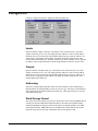
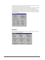
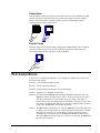
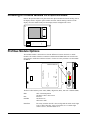
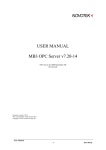
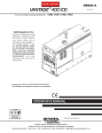
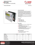
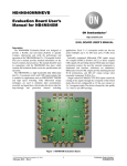
GE
Intelligent Platforms
User Manual
PROFIBUS
01
78
9
23
23
78
0 1
56
9
4
ON
4
56
1
Profibus User Manual
800-1000-105
Revision E
April, 2010
This manual was produced by Total Control Products, Inc., Charlottesville Virginia.
Copyright 1998-2001, Total Control Products, Inc. All rights reserved.
Manual design and implementation by Glenn Rodgers.
Information in this document is subject to change without notice and does not represent a commitment on the part of
Total Control Products, Inc. The software described in this document is provided under a license agreement. The
software may be used or copied only under the terms of the agreement. Only one copy of the software may be made for
a backup.
Total Control Products, Inc. makes no warranty, either expressed or implied, including but not limited to any implied
warranties of merchantability or fitness for a particular purpose, regarding these materials and makes such materials
available solely on an "as-is" basis.
In no event shall Total Control Products, Inc. be liable to anyone for special, collateral, incidental, or consequential
damages in connection with or arising out of purchase or use of these materials. The sole and exclusive liability to Total
Control Products, Inc., regardless of the form of action, shall not exceed the purchase price of the materials described
herein.
No part of this manual may be reproduced or transmitted in any form or by any means, electronic or mechanical,
including photocopying, recording, or information storage and retrieval systems, for any purpose other than the
purchaser's personal use, without the express written permission of Total Control Products, Inc.
GE Intelligent Platforms, Inc.
http://www.ge-ip.com/
Chapter 1
Profibus
The most important advantages of PROFIBUS in comparison with other fieldbuses are the
stable international standard EN 50 170 and the universal features covering a wide range of
applications in manufacturing, process and building automation. Open and vendor
independent communication with PROFIBUS is not just a vision. Its success has been
demonstrated in over 100,000 applications. Independent market studies confirm that
PROFIBUS with its market share of more than 40% leads the market for open industrial
fieldbus systems in Germany and Europe.
Leading manufacturers of automation technology stand behind PROFIBUS with all their
know how and offer a wide range of innovative products and services which are listed and
continuously updated in the PROFIBUS product guide. The PROFIBUS product guide is
available free of charge from the offices of the PROFIBUS User Organization. A complete
technical description of PROFIBUS can be found at the Internet site listed below.
The PROFIBUS User Organization can be viewed on the Internet under:
http://www.profibus.com.
Setup
The drawing shows the setup dialog box for Profibus Protocol. Click the Configure I/O
button to select the number of Input and Output words.
User Manual PROFIBUS
1
Configure I/O
Click the Configure I/O button to display the following dialog box.
Inputs
Enter the number of Input words up to a maximum of 100 words (200 bytes). The Start
Address is normally set to 0. You can change the Start Address to create an offset address.
Different devices can reference the same Profibus address but may require an offset for one
of the devices. Changing the Start Address will change the address ranges shown in the
Profibus DP Protocol dialog box. The Start Address is provided so that the user can align the
tag address entered in Quick Designer with the mapped address in the PLC or host device.
Outputs
Enter the number of Output words up to a maximum of 100 words (200 bytes). The Start
Address is normally set to 0. You can change the Start Address to create an offset address.
Different devices can reference the same Profibus address but may require an offset for one
of the devices. Changing the Start Address will change the address ranges shown in the
Profibus DP Protocol dialog box.
Addressing
Some PLCs use Byte addressing while others use Word addressing. Select Addressing on
Byte Boundaries or Word Boundaries, based on your PLC type. The range of valid addresses
will be displayed in the Profibus DP Protocol dialog box, which appears when you close the
configuration dialog box.
Word Storage Format
This option allows selecting the way bytes are arranged into words. Selecting MSB-LSB will
arrange bytes from the MSB (Most Significant Byte) to the LSB (Least Significant Byte).
Selecting LSB-MSB will arrange bytes from the LSB (Least Significant Byte) to the MSB
(Most Significant Byte. MSB-LSB will store the MSB in the current address byte and the
LSB will be stored in the next byte. LSB-MSB is stored in the opposite order.
2
User Manual PROFIBUS
Double Word Storage Format
This option allows selecting the way words are arranged into double words. Selecting MSWLSW will arrange words from the MSW (Most Significant Word) to the LSW (Least
Significant Word). Selecting LSW-MSW will arrange words from the LSW (Least
Significant Word) to the MSW (Most Significant Word). MSW-LSW will store the MSW in
the current address word and the LSW will be stored in the next word. LSW-MSW is stored
in the opposite order.
Power On State
A Series B module contains a Battery Backup RAM circuit that maintains a copy of the
inputs. The input states can be restored (Restore Inputs) or cleared (Clear Inputs) when
power is applied.
Note: ONLY Series B modules contain the Battery Backup RAM circuit. Series B modules
can be identified by the model number on the product label. Example: MODEL: QPI-PBS202 SERIES B
Example 1:
In this configuration example, Input Words are set to 64, Output Words are set to 64 and
Addressing is set to Word Boundaries.
User Manual PROFIBUS
3
When the OK button is clicked, the following Profibus DP Protocol dialog box will appear.
The valid address ranges are shown for all types of variables.
The number of Input and Output words selected will determine the valid address range limits
for each variable type. The variable type names are fixed and are displayed in a cell
corresponding to the addressing type. For example, in the following dialog box, the number
of Input Words is set to 64. The variable name for Input Words is IW and the range for 64
words is IW0 to IW63. Output Words are also set to 64, so the variable name is QW and the
range is QW0 to QW63.
Example 2:
In this configuration example, Input Words are set to 64, Output Words are set to 64 and
Addressing is set to Byte Boundaries.
4
User Manual PROFIBUS
When the OK button is clicked, the following Profibus DP Protocol dialog box will appear.
The valid address ranges are shown for all types of variables.
When byte addressing is selected, the valid address ranges appear in a different format in the
Profibus DP Protocol dialog box.
The number of words selected will determine the range limits for each variable type. The
variable type names are fixed and are displayed in a cell corresponding to the addressing
type. For example, in the following dialog box, the number of Input Words is set to 64. The
variable name for Input Bits is I and the range for 64 words is I0.0 to I127.7. Output Words
are also set to 64, so the variable name for bit Outputs is Q, with the range of Q0.0 to
Q127.7.
A byte is 8 bits, therefore the addressing method is to use a period as the bit delimiter in the
addressing format. For example, I0.0 is bit 0 of Word 0, and I0.7 is bit 7 of Word 0.
Profibus DP Protocol Dialog Box
The number of Input and Output words and the addressing will determine the valid address
range limits for each variable type. The variable type names are fixed and are displayed in a
cell corresponding to the addressing type. A word addressing example is shown below.
User Manual PROFIBUS
5
GSD Files
PROFIBUS devices have different performance characteristics. Features differ in regard to
available functionality (i.e., number of I/O signals and diagnostic messages) or possible bus
parameters such as baud rate and time monitoring. These parameters vary individually for
each device type and vendor. To achieve simple Plug and Play configuration of PROFIBUS,
the characteristic features are specified in an electronic data sheet sometimes called a device
data base file or GSD file. Standardized GSD data expand open communication up to the
operator control level. Using configuration tools based on GSD files makes integration of
devices from different vendors in a bus system simple and user-friendly.
The Device Data Base Files provide a clear and comprehensive description of the
characteristics of a device type in a precisely defined format. The GSD files are prepared
individually by the vendor for each type of device and made available to the user in the form
of a device data base sheet and a device data base file. The precisely defined file format
permits the configuration system to simply read in the device data base file of any
PROFIBUS-DP device and automatically use this information when configuring the bus
system. Project engineers are spared the time-consuming job of determining this information
from the technical manuals. During the configuration phase, the configuration system
automatically performs checks for input errors and consistency of the data entered in relation
to the total system.
6
User Manual PROFIBUS
GSD File Format
The device data base file is divided into three parts:
General specifications
This section contains vendor and device names, hardware and software release states, baud
rates supported, possible time intervals for monitoring times and the signal assignment on
the bus plug connector.
DP master-related specifications
This section contains all parameters which only apply to DP master devices (i.e., the
maximum number of slaves which can be connected or upload and download capabilities).
This section does not exist for slave devices.
DP slave-related specifications
This section contains all specifications related to slaves (i.e., the number and type of I/O
channels, specification of diagnostic tests and information on the consistency of the I/O
data).
GSD File Installation
Total Control Products has created a GSD file for use with the QuickPanel and vendor
specific Profibus protocol. You must install the GSD file as described in the README.TXT
file, which is found on the protocol release disk. The file name is Hms-1002.gsd.
GSD files of all PROFIBUS-DP devices that are tested for their conformity to the PROFIBUS
standard are available in the GSD library on the World Wide Web Server of the PROFIBUS
User Organization for free downloading. When the Profibus protocol for Total Control has
been tested for conformity, it will appear in the GSD library. The address is:
http://www.profibus.com.
Ident Number
Every type of a DP slave must have an ident number. Masters require this number to enable
them to identify the types of devices connected without creating significant protocol
overhead. The master compares the ident number of the connected DP devices with the ident
number specified by the configuring tool in the configuration data. Transfer of user data is
not started until the correct device types with the correct station addresses have been
connected on the bus. This provides a high degree of security against configuration errors.
User Manual PROFIBUS
7
Cables
The PROFIBUS standard defines two variations of the bus cable for PROFIBUS - FMS and
PROFIBUS - DP. Type A is especially recommended for high transmission speeds ( > 500
kBaud) and permits doubling of the network distance in comparison to Type B. Type B
should only be used at low baud rates and low requirements on the network distances.
Type A
Cable specification Type A for PROFIBUS - FMS and PROFIBUS - DP
Impedance :
135 up to 165 Ohm at a frequency of f from 3 up to 20 MHz.
Cable capacity : < 30 pF per meter
Core diameter : > 0,34 mm², corresponds to AWG 22
Cable type :
twisted pair cable. 1 x 2 or 2 x 2 or 1 x 4 lines
Resistance :
< 110 Ohm per km
Signal attenuation :
max. 9 dB over total length of line section
Shielding :
CU shielding braid or shielding braid and shielding foil
Type B
Cable specification Type B for PROFIBUS - FMS and PROFIBUS - DP
Impedance :
100 up to 130 Ohm at a frequency of f > 100 kHz
Cable capacity : typ. < 60 pF per meter
Core diameter : > 0,22 mm², corresponds to AWG 24
Cable type :
twisted pair cable. 1 x 2 or 2 x 2 or 1 x 4 lines
Signal attenuation :
max. 9 dB over total length of line section
Shielding :
CU shielding braid or shielding braid and shielding foil
Shielding
EN 50170 leaves it to the user if a shielded or unshielded cable shall be used. In areas with
no disturbances unshielded cable is permitted. The following reasons however make it
advisable to use a shielded cable:
a) An area free of disturbances will only exist inside of a shielded cabinet. As soon as a relay
is mounted into the cabinet non interference is no longer ensured.
b) The use of unshielded cables requires additional protection mechanisms at the bussignal
inputs against overvoltage.
Therefore it is recommended to always use shielded cable.
This recommendation is also applicable for eventually needed supply cables from external
power supplies to the PROFIBUS devices. (e.g. repeaters).
Double shielded lines are especially suitable for surroundings with heavy electromagnetic
interference. In order to guarantee optimal protection the outer shield (shielding braid) and
the inner shield (shielding foil) should be connected to ground on both cable ends flatly with
a ground termination clip.
When using a shielded bus cable it is recommended to connect the shield on both sides low
inductively with the protective ground in order to achieve optimal electromagnetic
compatibility. In case of separate potentials (e.g. refinery) the shield should be connected
only at one side of the bus cable to the protective ground.
8
User Manual PROFIBUS
Connectors
Cable assemblies, cable and connectors can be obtained from several manufacturers. Make
sure that you always connect the same wires to the same terminal A or B (for example,
always connect green wire to terminal A and the red wire to terminal B). A typical
connector/cable assembly is shown below.
Ferrite Cores
Attach the ferrite cores to the data cables leading to the Profibus module. This will help to
suppress the effect of any noise created by surrounding equipment. TDK ferrite cores
(ZCAT2035-0930A) or their equivalent, are recommended.
FERRITE
CORE
PLC Comm Errors
In the event of a communication problem, error messages are displayed on a status line at
the bottom of the display.
02:FF:A0 Error initializing Anybus module
02:FF:01 Incorrect Anybus module ID
02:FF:02 Anybus module watchdog time-out (module lockup)
02:FF:03 Network Error - Network not connected
02:FF:10 The timestamp in BBRAM does not match timestamp downloaded. Since the
BBRAM is invalid, the inputs will be cleared. This is a non-critical error and it
will only be displayed for 2 seconds after power up or reboot. Note that it is
normal for this error to be displayed after downloading a new project since a new
time stamp is included in the download. If this error is displayed after a reboot or
power-cycle, the BBRAM in the unit may be defective.
02:FF:11 The BBRAM has a checksum error. Since the BBRAM is invalid, the inputs will
be cleared. This is a non-critical error and it will only be displayed for 2 seconds
after power up or reboot. It is possible that the power was lost or the QP was
rebooted at the exact instance we were updating the BBRAM and therefore the
data in the BBRAM is invalid. However, if this error occurs often, the BBRAM in
the unit may be defective.
User Manual PROFIBUS
9
Tag Variables
Valid tag variable names and address ranges are shown in the Profibus DP Protocol dialog
box when you configure the protocol.
The number of Input and Output words and the addressing will determine the valid address
range limits for each variable type. The variable type names are fixed and are displayed in a
cell corresponding to the addressing type.
Example 3, Byte Addressing: Input Words = 64, Output Words = 64, Input start address =
0, Output start address = 0.
Name
I (Input Bit)
Q (Output Bit)
IB (Input Byte)
QB (Output Byte)
IW (Input Word)
QW (Output Word)
ID (2 Word Input)
Address range
I0.0 to I127.7
Q0.0 to Q127.7
IB0 to IB127
QB0 to QB127
IW0 to IW126
QW0 to QW126
ID0 to ID124
QD (2 Word Output) QD0 to QD124
DWORD
ID0
BYTE
WORD
IB0
IW0
IB1
ID1
ID124
DWORD
QD0
IW1
IW2
IB2
ID2
Value range
0 to 1
0 to 1
0 to 255
0 to 255
-32768 to 32767
-32768 to 32767
-999999999 to
999999999
-999999999 to
999999999
QD1
Write
Y
N
Y
N
Y
N
Type
Bit
Bit
Byte
Byte
Word
Word
Y
DWord
N
Dword
BYTE
WORD
QB0
QW0
QB1
QB2
QD2
IB3
QB3
IB4
QB4
IB5
QB5
QD124
IB124
IB125
IB126
QW1
QW2
QB124
QB125
QB126
IW126
IB127
QW126
QB127
For the combination of a W, DW, W, the following example shows the layout.
BYTE
IW0
IB0
BYTE
QW0
IB1
ID2
IW6
IB2
QB1
QD2
QB2
IB3
QB3
IB4
QB4
IB5
QB5
IB6
IB7
10
QB0
QW6
QB6
QB7
User Manual PROFIBUS
Example 4, Word Addressing: Input Words = 64, Output Words = 64, Input start address
= 0, Output start address = 0.
Name
I (Input Bit)
Q (Output Bit)
IW (Input Word)
QW (Output Word)
ID (2 Word Input)
Address range
I0.0 to I63.15
Q0.0 to Q63.15
IW0 to IW63
QW0 to QW63
ID0 to ID62
QD (2 Word Output) QD0 to QD62
DWORD
ID0
WORD
IW2
ID62
DWORD
IW0
IW1
ID1
ID2
Value range
0 to 1
0 to 1
-32768 to 32767
-32768 to 32767
-999999999 to
999999999
-999999999 to
999999999
QD0
Write
Y
N
Y
N
Type
Bit
Bit
Word
Word
Y
DWord
N
Dword
WORD
QW0
QW1
QD1
QW2
QD2
IW3
QW3
IW4
QW4
IW5
QW5
IW62
QD62
IW63
QW62
QW63
For the combination of a W, DW, W, the following example shows the layout.
WORD
WORD
IW0
IW0
QW0
QW0
ID1
IW1
QD1
QW1
IW2
IW3
IW3
IW4
User Manual PROFIBUS
QW2
QW3
QW3
QW4
11
Installing a Profibus Module on a QUICKPANEL
Remove the option module cover plate. Insert the option module tabs into the mating slots in
the display chassis. Align the option module connector with the mating connector on the
display. Press the module firmly into the display chassis and tighten the screws.
Profibus Module Options
The Profibus module is shown below. Note the differences between the Series A and B
modules. The module contains a terminator switch marked TERM. Move the switch to the
ON position to enable the terminator resistors. Use the two rotary switches to set the NODE
ID address.
NODE
9
2
13
0 4
8 76 5
1 23
0
4
9
8 7 65
1
ON
ProfiBus
IND. Cont. EQ
8M89
Listed
TERM
ERR
PWR
DIA
Serial No: XXXXXX
QPI – PBS – 202 - D
Module Profibus DP Slave
ID
SERIES B MODULES
The three LEDs indicate power status (PWR), diagnostics (DIA), and error condition (ERR).
ERR
DIA
POWER
NODE ID
12
OFF= Normal Operation
ON=Bus is OFF or has an error
Not used
ON=Power On
OFF=Power OFF
The rotary switch on the left is the x10 digit and the switch on the right
is the x1 digit. Therefore, is the left switch is set to 5 and the right
switch is set to 3, then the address is 53.
User Manual PROFIBUS
Installing a Profibus Module on a QUICKPANEL jr.
Align the option module connector with the mating connector on the display. Attach the
power wires to the terminal block on the display. Press the module firmly into the display
chassis and tighten the screws. Plug the power connector into the module. The option
module is shown below.
SLAVE
6.00
1.44
TOTAL CONTROL PRODUCTS, INC.
2001 N. JANICE AVE. MEL ROSE PARK, I L. 60160
MODEL : XXXXXXXXXXXXXXXXXXXXXX
SERIAL NO.: XXXXXX
01
9
456
23
78
01
9
456
23
4.20
78
ON
DIA
PWR
VERSION: XXXX
TERM ERR NODE ID
MFG. DATE: XX/XX/XX
ProfiBus
WARNING EX PLOS ION HAZARD
DO NOT conn ect/di sconn ect eq uipme nt unle ss are a is kn own
to be n onha za rd ous. Po rt is for system set-up a nd diag nostics.
24 VDC
+
-
RED
GRN
BLK
User Manual PROFIBUS
13