1
4.4 - Configuration register 1
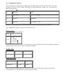
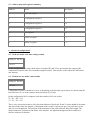
This 5 bit register is mainly used to configure the operating mode of the N110 TDC. The N110 can be
operated in "normal" or "test" modes. Thereafter we only consider the "normal" case. Test modes are
addressed in chapter 6.
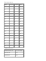
bit
Meaning
Value
0
Mode select
0= 2D, 1= Multihit
1-3
Reserved
should be 0
4
Mode type
0= Normal, 1= Test
In future, new operating modes could be implemented and selected using the reserved bits.
The Configuration register 1 resets to zero after power up.
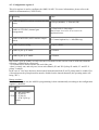
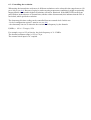
Rotary switches:
Bits 1-3 are stripped out, therefore
Label
Value
CFG1
0 = 2D
1= Multihit
2 = sum (see 6)
3 = raw (see 6)
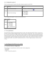
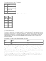
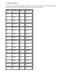
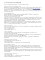
Depending on the operating mode, the 3 bit status word (presented at the front panel output port together
with the 14 bit X and 14 bit Y value) is formatted as follows.
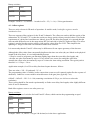
2D data format
S2
S1
S0
0
0
0
Multihit data format
S2
S1
S0
Event parity
Y valid
X valid
The event parity bit toggles upon arrival of every common start. This may be used to sort out the
following hits if several of them occur during the gate duration.