1
Green led GATE continues has before.
Green led RDY should continue almost has before, but in the case most events are being rejected.
For an accurate monitoring of the pile up rejection you may count the GATE output (detected events)
versus the STROBE output (accepted events). At high counting rate (above 0.5 MHz) you may monitor
the direct anode from the detector versus the GATE from N110. This measures the dead time of the N110
(plus some pile up activity).
9) Set up the offset registers
Depending on your acquisition system you may use (or not) the offset registers. See 4.3. When used, fine
tunning is necessary which is best achieved through a remote computer and the serial line.
10) Use our favorite acquisition system
It works. Congratulations!
It does not work. It is clearly a software issue. Call the Expert(s).
11) take a coffee break.
It never hurts.
12) Back from the coffee break
It still works. You are an Expert, too.
It still does not work. Check the cable to the acquisition system (just in case the software would work).
13) Beam lost
That's life.
Back to home or next step.
14) Is the detector (so) good?
A nice feature of N110 is the sum recording mode of operation (see 6.2).
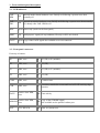
CFG1 (rotary switch) = 2.
CFG1 (serial line address 1) = 0x10 (beware serial differs from switch).
CFG2 (serial line address 2) = 0x34 (beware serial differs from switch).
You should observe peaks (one for X, one for Y), the position of which is a measurement of the delay line
length. The sharper and more symetrical the best. You don't get anything: did you used a Fe source in
replacement of the (lost) beam?