1
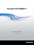
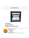
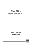
XNB-46S Super Narrow Bezel Multi-Vision LCD Monitor PRODUCT INTRODUCTION Revision 1.2 Nov 2009 XMPDisplay Co., Ltd. Head Office & Factory 265-1 Palbok-Dong 2Ga Deokjin-Gu Jeonju-City Korea (R.O.K) 561-843 Seoul Office 3FI. ANT Bldg. 197-8 Dongkyo-Dong, Mapo-Gu, Seoul Korea (R.O.K) 121-819 RoHS Compliant 2002/95/EC Note : The specification is subject to change without prior notice. ⓒ Copyright 2009 XMPDisplay Co., Ltd. Page 1 of 48 Thank you for purchasing our Super Narrow Bezel LCD Monitor ”XNB-46S” This manual describes how to use the product and notes in use. Please read the manual carefully before using it. After reading the manual, keep it with the certificate for you to refer to it whenever you need. If you have any question or any problem occurs, please contact to the provider or the A/S center immediately. ※Pausing static picture for around 3 hours may cause an afterimage effect. Notice of users Class A digital device It is a device designed for business purpose with a safety certificate for electromagnetic interference, which user should be mindful of. List of Parts VGA Cable RS-232 Cable ⓒ Copyright 2009 XMPDisplay Co., Ltd. DVI Cable Power Cable Stand Unit (Option) Page 2 of 48 Contents 1. GENERAL DESCRIPTION ........................................................................................................................................ 5 2. DATA SHEET ................................................................................................................................................................6 2.1. Input, Output Terminals ............................................................................................................................................ 6 2.2. XNB-46S System Data sheet..................................................................................................................................... 7 2.3. Dimension, Weight and Accessories ....................................................................................................................... 8 2.4. TFT LCD Panel Specifications.................................................................................................................................... 9 2.5. Regulation .................................................................................................................................................................. 10 3. ELECTRICAL SPECIFICATIONS.......................................................................................................................... 11 3.1. Input signal ................................................................................................................................................................ 11 3.2. Output Signals........................................................................................................................................................... 12 3.3. Preset Signal Timings............................................................................................................................................... 13 3.4. Power Supply(SMPS) ................................................................................................................................................ 15 3.5. Power Management ................................................................................................................................................. 15 4. MVCSP( MULTI VISION CONTROL SYSTEM PROGRAM) .................................................................. 16 4.1. Setting and Operation of monitor (Main RS 232 Controller Windows) ........................................................ 16 4.2. Setting “Multi Screen” Configuration ................................................................................................................... 17 4.3. Configuration of various modes ............................................................................................................................ 19 4.4. Scenario Control ....................................................................................................................................................... 20 4.5. Setting Color Control ............................................................................................................................................... 21 4.6. Picture Control .......................................................................................................................................................... 22 4.7. Remote Control ......................................................................................................................................................... 22 4.8. ETC ............................................................................................................................................................................... 23 5. GENERAL FUNCTION AND CABLE CONNECTION ................................................................................ 24 5.1. Auto Adjust Function ............................................................................................................................................... 24 5.2. Set ID Switch Configuration ................................................................................................................................... 24 5.3. DVI CONNECTION .................................................................................................................................................... 25 5.4. RS-232 CONNECTION .............................................................................................................................................. 25 5.5. RS-232 Control .......................................................................................................................................................... 26 6. OSD FUNCTION ...................................................................................................................................................... 29 6.1. OSD Key Function ..................................................................................................................................................... 30 ⓒ Copyright 2009 XMPDisplay Co., Ltd. Page 3 of 48 6.2. Remote Control ......................................................................................................................................................... 31 7. PRODUCT PERFORMANCE................................................................................................................................ 38 7.1. Test condition ............................................................................................................................................................ 38 7.2. Luminance .................................................................................................................................................................. 38 7.3. Geometry.................................................................................................................................................................... 39 7.4. Rotation (TBD – defined when CS sample available) ........................................................................................ 39 8. INSPECTION CRITERIA (TBD – DEFINED WHEN CS SAMPLE AVAILABLE) .............................. 40 8.1. Conditions .................................................................................................................................................................. 40 8.2. Dot Defect Criteria ................................................................................................................................................... 40 8.3. Definition of Uniformity Defect ............................................................................................................................. 41 8.4. Spot and Linear Type Inspection ........................................................................................................................... 41 8.5. Light Leakage ............................................................................................................................................................ 41 8.6. Visual Appearance Defect Criteria ......................................................................................................................... 41 8.7. Accessories ................................................................................................................................................................. 41 9. NOTICE FOR HANDLING.................................................................................................................................... 42 10. MECHANICAL SPECIFICATIONS.................................................................................................................. 43 10.1. Master Frame ......................................................................................................................................................... 43 10.2. Rating Label ........................................................................................................................................................... 43 10.3. Carton Box ............................................................................................................................................................. 43 10.4. Weight ..................................................................................................................................................................... 43 11. ENVIRONMENT CONDITIONS..................................................................................................................... 44 11.1. Temperature, Relative Humidity......................................................................................................................... 44 11.2. Random Vibration test (Packing) ....................................................................................................................... 44 11.3. Random Vibration test (Unpacking-Operational) ........................................................................................... 44 11.4. Drop test (Packing) ............................................................................................................................................... 44 12. TROUBLESHOOTING CHECKLIST ............................................................................................................... 45 13. FIGURE ..................................................................................................................................................................... 46 13.1. Outline Dimension ................................................................................................................................................ 46 13.2. Rating Label ........................................................................................................................................................... 47 13.3. Carton box print.................................................................................................................................................... 48 ⓒ Copyright 2009 XMPDisplay Co., Ltd. Page 4 of 48 1. General Description General Description This document is the specification of 46” TFT-LCD MULTI VISION MONITOR for application of DID, which is based by SAMSUNG LTI460AA04, the first Ultra Narrow Bezel LCD Product world wide. XNB-46S is a High quality TFT-LCD multi vision solution for display device having RoHS. General Features - Resolution : WXGA (1366 * 768 @ 60Hz) Recommend PC(VGA)/DVI : 1920 * 1080 @ 60Hz(Input only) at Multi COMPONENT : 1080p(Input only) at Multi - Image Screen Input Signal: PC(VGA) / DVI / COMPONENT / SVHS / CVBS - ROHS Compliance - Supports VESA DDC 2B - Support RS-232 Data transmission - On Screen display(OSD) Electrical Specification Input Power : Input power is required as below Voltage : Universal Voltage [ 90Vac – 264Vac / 47Hz – 63Hz ] Consumption : 300 [W] (Max) Power Management Mode V-Sync H-Sync Video Power Consumption ON Pulse Pulse Active Less than 300 [W] Off (Stand by) - - Blank Less than 5 [W] < Top View > < Front View > ⓒ Copyright 2009 XMPDisplay Co., Ltd. < Back View > Page 5 of 48 2. Data Sheet 2.1. Input, Output Terminals ① . DVI IN / OUT - Computer digital video signal in/output. ② . D-SUB IN / OUT - Computer analog (R,G,B) signal in/output. ③ . S-VIDEO IN / OUT - Super video (Y/C) signal in/output. ④ . CVBS IN / OUT - Composite video signal in/output. ⑤ . COMPONENT IN / OUT - Component (y, Pb, Pr) signal in/output. ⑥ . RS-232 (C0ntrol) - External communication input. ⑦ . DIP Switch - Monitor ID & I²C/RS-232 switch setting. ⑧ . AC INPUT / OUTPUT ⓒ Copyright 2009 XMPDisplay Co., Ltd. Page 6 of 48 2.2. XNB-46S System Data sheet Item Specification LCD Module Model Name XNB-46S Pixel Pitch 0.7455(H)x0.7455(V) [mm] Active Display Area 1018.353(H) x 572.544(V) [mm] Resolution WXGA 1366 x 768 pixels (16:9) Colors 16,777,216 (8 bit) Luminance of white 500cd/m2 (Typ,) 700cd/m2 (Max) Contrast Ratio 3,000:1 (Typ) Viewing Angel U/D/L/R = 89º Response Time 8ms (GTG) Bezel Super narrow bezel Pixel Clock 25.2MHz-165MHz Power Management None Plug and Play Yes / DDC2B Control IR(Remote Control) , OSD Key(8 keys), RS-232(DSUB 9 Pin) Speaker / Audio Output None Horizontal Range 30.0 – 68.0 KHz Vertical Range 50 +/- 1Hz, 60Hz +/- 1Hz Pixel Clock 25.2MHz-165MHz Connector DSUB-15P IN/OUT , DVI-D IN/OUT Sync Separate 640x480-60,800x600-60,1024x768-60,1280x1024-60, 1366x768-60,1366x768-50,1368x768-60,1368x768-50, 720p-60,1080p-60, 720p-50,1080p-50 BNC IN/OUT VGA / DVI Input / Output Signal Resolution Connector Component S-Video CVBS Resolution 480i,480p,720p-60,1080i-60,1080p-60, 576i,576p,720p-50,1080i-50,1080p-50 Connector Color System Connector S-Terminal IN/OUT NTSC / PAL BNC IN/OUT Color System NTSC / PAL Control Signal DSUB 9 Pin IN / OUT( Through DVI cable) For RS-232 Control Power Supply Universal 300W(Max) (100-240) Current Rating 2.73A @110V , 1.36A @220V Operation Environment (*1) Storage Environment(*1) Temperature 5 ~ 40 ºC Humidity 20 – 80% (without condensation) Temperature -20 ~ 60 ºC Humidity 10 – 90% (without condensation) ⓒ Copyright 2009 XMPDisplay Co., Ltd. Page 7 of 48 Note 1) Temperature and Relative humidity range 2.3. Dimension, Weight and Accessories Complied regulatory and Guidelines Dimension Defined at 1.2 Regulation Net without stand W 1026.1mm / H 580.2mm / D 98.1 mm Net without stand(Glass) N/A Gross W: 1200mm / H: 778mm D: 370mm Without Glass Weight Net < 29.8 kg Gross < 39.6 kg Net N/A Gross N/A With Glass Accessories ⓒ Copyright 2009 XMPDisplay Co., Ltd. - Remote Controller ( with Battery ) - DVI cable - D-SUB cable - RS232 cable(Serial Cable) - User’s Manual(English) Page 8 of 48 2.4. TFT LCD Panel Specifications Item Specifications Unit Model Samsung TFT LCD LTI460AA04 1025.653(WTYP)x579.844(HTYP) Module Size 59.43(DMAX) mm Weight 16,000(Max) Pixel Pitch 0.7455(H)x0.7455(V) mm Active Display Area 1018.353(H) x 572.544(V) mm Surface Treatment Haze 40%, Hard-coating(3H) Display Colors 8 bit – 16.7M Number of Pixels 1366 (H) 768 (V) Color Filter RGB vertical stripe Display Mode SPVA, Normally Black Luminance of White 700(Typ) Contrast ratio (Center of Screen) Back Light Unit (BLU) 2500:1(Min) , 3000:1 (typ.) Back light unit operating life time 50,000 Response Time Rising 10(typ) Falling 6(typ) G-to-G 8(typ) colors pixel cd/m2 Rx 0.643 Ry 0.328 Gx 0.271 Gy 0.599 Bx 0.143 By 0.0060 Wx 0.280 Wy 0.290 Green Blue White Color Temperature Viewing Angle(Typ.) g (*1) CCFL Red Color Chromaticity (CIE 1931) Remarks 10000 Horizontal -89 to 89 Vertical -89 to 89 Brightness Uniformity (9 Points) ⓒ Copyright 2009 XMPDisplay Co., Ltd. 25 Hour Brightness decrease of 50% msec (*3) TYP. +/0.03 K Degree % CR>=10(*2) (*4) Page 9 of 48 2.5. Regulation The monitor shall be approved / licensed / certified as the Model KT-LS46LMD-S * NOTE : USE RESTRICTIONS AND LIMITATIONS This product is not authorized for use in life support devices or systems, military application, or other application which propose a significant risk of personal injury. Therefore, the product shall not be used for such purpose. Regulation Safety EMC (Class A) Others Country CB Report UL(NRTL) CSA/c-UL CE-Marking TUV-GS GOST-R CCC PSB NOM IRAM KCC FCC-A DOC-A CE-Marking C-Tick-B GOST-R WEEE SB 50 RoHS Mercury Regulation EuP International USA Canada EU Germany Russia China Singapore Mexico Argentina South Korea USA Canada EU Australia Russia International US (California) EU USA EU Configuration KT-LS46LMD-S Y Y Y Y Y Y Y Y Y Y Y Y TBD • Regulation: Safety(*: Include EMI or EMC Requirements) - UL (U.S.A) - CSA / c-UL - CE-Marking : UL60950-1 : CAN /CSA -22.2 No.60950-1 : EN60950-1 EMI / EMC - FCC (USA) - DOC (CSA) - CE -KCC : Part 15B : EN55022(EMI), EN55024(EMS) : EN 61000-4-2(ESD) / EN 61000-4-3(RS) : EN 61000-4-4(EFT) / EN 61000-4-5(SURGE) : EN 61000-4-6(CS) / EN 61000-4-11(DIP) : EN 61000-3-2 / EN 61000-3-3 / EN 61000-4-8 : ⓒ Copyright 2009 XMPDisplay Co., Ltd. Page 10 of 48 3. Electrical Specifications 3.1. Input signal Specification Input Min Signal Frequency PC(VGA) / DVI Componen t Separate (H,V) Sync (TTL) Max Unit RGB 0.714 DVI T.M.D.S H 30.0 - 68.0 KHz V 49 - 61 Hz High 2.0 - 5.0 Low 0 - 0.8 V Max length : 10 m DVI (Set1 to Set2) Max length : 1.8 m YPbPr Y 1.0 Pb/Pr 0.7 CVBS (Composite) PAL VIDEO NTSC S-VHS (Y/C) PAL RS-232C(PC to MNT) ⓒ Copyright 2009 XMPDisplay Co., Ltd. Remark Vp-p DVI (PC to MNT) NTSC CONTROL Typ TBD 0.714 0.286 0.7 0.3 Sync Signal Vp-p Sync Signal 1.0 0.286 Sync Signal 1.0 0.3 Max length : 10 Sync Signal m TBD Page 11 of 48 3.2. Output Signals Specification Output Unit Min Typ Remark Max RGB 0.714 Vp-p DVI T.M.D.S H 30.0 - 68.0 KHz V 49 - 61 Hz High 2.0 - 5.0 Low 0 - 0.8 Signal PC(VGA) / DVI Frequency Separate (H,V) Sync (TTL) Componen t V Y 1.0 Pb/Pr 0.7 YPbPr 0.714 NTSC 0.286 CVBS (Composite) Sync Signal 0.7 Vp-p PAL 0.3 Sync Signal VIDEO 1.0 NTSC 0.286 S-VHS (Y/C) Sync Signal 1.0 PAL 0.3 CONTROL RS-232C (‘n’ MNT to ‘n+1’ MNT) ⓒ Copyright 2009 XMPDisplay Co., Ltd. Max sets : 16 Sync Signal sets Page 12 of 48 3.3. Preset Signal Timings < Horizontal Video & Sync > < Vertical Video & Sync > 3.3.1. Component signal Signal Timing Frame Frequency [Hz] 480i 29.97 480p 576i 576p 720p 1080i 1080p 59.94 25.0 50 59.94 50 29.97 25.0 59.94 50 Entire Lines 525 525 625 625 750 750 1125 1125 1125 1125 Effective Lines 480 480 576 576 720 720 1080 1080 1080 1080 Aspect Ratio 4:3 16:9 4:3 16:9 16:9 16:9 16:9 16:9 16:9 16:9 15.73 31.46 15.62 31.25 44.95 37.50 33.71 28.125 67.42 56.25 Line Frequency [KHz] ⓒ Copyright 2009 XMPDisplay Co., Ltd. Page 13 of 48 3.3.2. PC(VGA) Resolution Description 640 Freq [KHz] H O R I Z O N T A L 1024 1366 1280 480 600 768 1024 768 31.468 37.879 48.780 63.981 47.700 A: Total [Dot] 800 1056 1936 1688 1782 B: Sync width [Dot] 96 128 96 112 144 C: Back Porch [Dot] 56 88 752 248 208 D: Active [Dot] 640 800 1024 1280 1366 E: Front Porch [Dot] 8 40 64 48 64 - + - + + 59.94 60.317 60.001 60.02 60.00 Polarity Freq [Hz] V E R T I C A L 800 A:Total [Line] 525 628 813 1066 795 B: Sync width [Line] 2 4 6 3 3 C: Back Porch [Line] 41 23 33 38 23 D: Active [Line] 480 600 768 1024 768 E: Front Porch [Line] 2 1 6 1 1 - + - + + 31.5 40.000 94.43 108.0 85.03 Polarity Pixel Clock [MHz] 3.3.3. DVI Signal Resolution Description Freq [KHz] H O R I Z O N T A L V E R T I C A L 1366 1368 1368 1280 1920 768 768 768 720(720p) 1080(1080p) 47.7 47.7 47.7 37.5 45 56.25 67.5 A: Total [Dot] 1766 1800 1768 1980 1650 2640 2200 B: Sync width [Dot] 144 144 144 40 40 44 44 C: Back Porch [Dot] 200 216 200 160 220 148 148 D: Active [Dot] 1366 1368 1368 1280 1280 1920 1920 E: Front Porch [Dot] 56 72 56 440 110 528 88 Polarity + + + + + + + Freq [Hz] 50 60 50 50 60 50 60 A:Total [Line] 954 795 954 750 750 1125 1125 B: Sync width [Line] 3 3 3 5 5 5 5 C: Back Porch [Line] 23 19 23 20 20 36 36 D: Active [Line] 768 768 768 720 720 1080 1080 E: Front Porch [Line] 1 1 1 5 5 4 4 + + + + + + + 84.238 85.896 84.33 74.25 74.25 148.50 148.50 Polarity Pixel Clock [MHz] ⓒ Copyright 2009 XMPDisplay Co., Ltd. Page 14 of 48 3.4. Power Supply(SMPS) Input Voltage 90 to 264 Vac Frequency 47 to 53 / 57 to 63 Hz Power Consumption 300W(MAX) 2.73A @110V , 1.36A @220V AC Leakage Current IEC 60950 STD Under 5mA Inrush Current (Cold Start) 40 Apeak / 220V Power Factor > 0.9 3.5. Power Management This function conforms DPMS of VESA. Table 3.4.1 . Power Management condition and status Power Consumption (W) DPMS H-sync V-sync Display LED On state ON ON Normal GREEN <300 W Not Connected OFF OFF “No Signal” Display GREEN < 300 W OFF ON “No Signal” Display GREEN < 300 W ON OFF “No Signal” Display GREEN < 300 W Stand by (Power off) N/A N/A No Display RED < 5W Complete N/A N/A No display OFF 0W Remarks Active off ⓒ Copyright 2009 XMPDisplay Co., Ltd. Page 15 of 48 4. MVCSP( Multi Vision Control System Program) 4.1. Setting and Operation of monitor (Main RS 232 Controller Windows) [Multi Vision Control System Program (MVCSP)] 4.1.1. Setting “Com Port” ⓒ Copyright 2009 XMPDisplay Co., Ltd. Page 16 of 48 4.2. Setting “Multi Screen” Configuration 4.2.1. Select a desirable X and Y number - X number represents the number of monitor columns and Y number represents monitor rows - The range of X, Y number is from 1 to 15 Ex) 3 x 3 screen setting 4.2.2. ID Setting ID of monitor set by DIP switch and set matching ID in MVCSP Set ID of MVCSP arbitrary (Default ID setting of MVCSP follow coordinate axis) - Double click desirable screen and set ID of MVCSP - ID of other screen set as same way. : The range of X,Y number is from 1 to 15 Default ID setting User set ID of MVCSP *Recommend – Use default setting 4.2.3. Select one out of 5 input sources such as DVI, PC, VIDEO, S-VIDEO and COMPONENT. -Select “ALL SET” I SET ID Block. -Select input mode in “MODE” block.: PC,DVI,COMPONENT,VIDEO,S-VIDEO(HDMI mode is reserved) [ALL SCREEN SELECTED] ⓒ Copyright 2009 XMPDisplay Co., Ltd. [PC MODE INPUT SELECTED] Page 17 of 48 4.2.4. Configure Multi Set - You can configure 1:1 display or multi display(Output signal control) <Multi display> -Check”ONE SET” in SET ID block -Set up “HMaxCell”, “VMaxCell and click “Apply” button each cell : The range of HMaxCell, VMaxCell number is from 1 to 15 : The range of Cell number is from 1 to 225 Ex) If “HMaxCell” =3, “VMaxCell”=3 then click “Apply” button 9 times (Set Cell No 1,2,3,4,5,6,7,8,9) [Set up Call No.1] [Set up Call No.2] [Set up Call No.3] [Set up Call No.4] Set up as above picture <1:1 display > -Check “ALL SET” in SET ID block. -Set up “HMaxCell”,VMaxCell” into 1 and click “Apply” button each cell cf) :HMaxCell”=1, “VMaxCell”=1 then click “Apply” button (Then Cell No change “1”) ⓒ Copyright 2009 XMPDisplay Co., Ltd. Page 18 of 48 4.3. Configuration of various modes 4.3.1. XNB-46S monitor supported various input mode - PC, DVI, S-VIDEO, VIDEO, COMPONENT (Yellow HDMI button is reserved) 4.3.2. Check “SET ID” (ALL SET/GROUP/ONE SET) - Select desirable screen(selected screen is displayed with red square box) and click input mode as you want. - Then selected screen color changed in specific input mode color. - You can configure other screen in the same way. - Selected screen would be converted into other input mode. ⓒ Copyright 2009 XMPDisplay Co., Ltd. Page 19 of 48 4.4. Scenario Control 4.4.1. XNB-46S monitor supported Scenario mode - Make a desirable configuration in multi Screen 4.4.2. Set “Time” in “Operation Control” (minimum set “Time” : 60sec.) - Click “Add” button to save first step in scenario. 4.4.3. Save different screen configuration in the same way - You can select ALL SET or GROUP. ⓒ Copyright 2009 XMPDisplay Co., Ltd. Page 20 of 48 4.4.4. Click “START” button in Scenario to display saved screen configuration. 4.4.5. Check “Repeat” to display saved configuration repeatedly Click “Remove” and “All Remove” button delete specific slide show operation or all slide show operation 4.5. Setting Color Control 4.5.1. READ operation - Select desirable screen and click “Read” button to read color data of selected set. - Before setting color control, select screen you wanted and read color data first. - Read operation work properly when you select only I set 4.5.2. In order to setting color control function of specific monitor, select “Color” tab. 4.5.3. Select desirable screen and set each item you want control 4.5.4. In order to control display values, you can input values direct in “EditBox” and press Enter key, or click -/+ button using mouse. - Check “ALL SET” to transmit command data to all connected monitor regardless of ID. ⓒ Copyright 2009 XMPDisplay Co., Ltd. Page 21 of 48 4.6. Picture Control 4.6.1. READ operation - Select desirable screen and click “Read” button to read picture data of selected set. - Before setting picture data, select screen you wanted and read picture data first. * Read operation work properly when you select only 1 set. 4.6.2. In order to Picture mode control of specific monitor , select “Picture” tab 4.6.3. Select desirable screen and set each item you want control - Picture mode - Picture size 4.6.4. “Auto adjust” button is available when input source is PC - For auto alignment adjust, click “Auto adjust” button. - Check “ALL SET” to transmit command data to all connected monitor regardless of ID. 4.7. Remote Control 4.7.1. In order to control OSD Menu of specific monitor, use “REMOTE” button of “IR/KEY” tab after selecting the specific monitor. - Check “ALL SET” to transmit command data to all connected monitor regardless of ID. ⓒ Copyright 2009 XMPDisplay Co., Ltd. Page 22 of 48 4.8. ETC 4.8.1. Aging Mode operation. - Select Aging Mode tap and select desirable mode you want. Ex) Off / Full White / Full Red / Full Green / Full blue 4.8.2. To check firmware version, you can click “FW Version Read” button ⓒ Copyright 2009 XMPDisplay Co., Ltd. Page 23 of 48 5. General Function and Cable Connection 5.1. Auto Adjust Function Auto adjust function is performed to detect the input signal format (H/V frequency, video active area, sync pulse and back-porch) by the internal scaler at PC(VGA) input mode. Adjustment items are H/V-position, Frequency (Clock) and Phase. Auto adjust function cannot setup perfectly at some PCs. In this case, the fine turning of “Frequency (Clock)” and “Phase” by manual are necessary. If you precede the “Auto Adjust” on character mode such as “Dos Prompt mode”, you also cannot setup perfectly. And if you precede the “Auto Adjust” on dark moving picture, you also cannot setup perfectly too. So you need preceding “Auto Adjust” at the bright, full sized and still image to get good “Auto Adjust” result. 5.2. Set ID Switch Configuration Note : - The X/Y coordinates are set to binary code. The DIP is used to select Monitor ID. - X : 1, 2, 3, 4 → 1(Low Bit) / 4(High Bit) 0 ~ 15 - Y : 1, 2, 3, 4 → 1(Low Bit) / 4(High Bit) 0 ~ 15 I²C/RS232 Switch Configuration First SET (WHICH IS RECEIVED SIGNAL DIRECTLY FROM PC OR OTHER DEVICE, NOT RELATED WITH MONITOR ID) - OTHER SET ⓒ Copyright 2009 XMPDisplay Co., Ltd. Page 24 of 48 5.3. DVI CONNECTION 5.4. RS-232 CONNECTION Only Set NO. 1 attach RS232 cable Always DVI cable attach for RS232 Control ⓒ Copyright 2009 XMPDisplay Co., Ltd. Page 25 of 48 5.5. RS-232 Control You can control this monitor by using a personal computer with RS-232 terminal. RS-232 data transmit through DVI Cable between each set.(w/o First set, using DDC data line- Pin no.6, 7) 5.5.1. RS-232 data flow Option 1 : Using DVI Cable) PC 1st SET 2ND SET 3TH SET …… (using by 9P RS-232 CABLE) (using by DVI cable – DDC data line) PC PC should be connected with 1st set only by using RS-232 CABLE for access EDID data. Other sets are connected together for RS-232 data transmission by using DDC data line in DVI cable. (Otherwise, only 1st set needs to check EDID DATA with PC.) Option 2 : Using DVI to RS-232 Cable) 1st SET 2ND SET (using by 9P RS-232 CABLE) (using by DVI to RS-232 Cable) 3TH SET …… PC should be connected with 1st set only by using RS-232 CABLE. Other sets are connected together for RS-232 data transmission by using DDC data line in DVI to RS-232 cable. 5.5.2. COM Port setting Protocol Baud rate Data Bits Parity bit Stop bit Flow control RS-232 9600bps 8 Bit None 1 bit None 5.5.3. Control command format 1) Direct control command. Head Set Id Command End 2 Bytes 3 Bytes 3 Bytes 1 Byte K: ALL PON . EX) K:ALLPON. => ALL SET POWER ON K:001CTU. => SET ID 001 SET CONTRAST 1 STEP UP 2) Value adjust command. Head Set Id Command Value End 2 Bytes 3 Bytes 3 Bytes 3 Bytes 1 Byte K: ALL PON 095 . EX) K:ALLCON095. => ALL SET CONTRAST ADJUST TO 95 LEVEL K:012BRT080. => SET ID 012 SET BRIGHTNESS ADJUST TO 80 LEVEL 3) Status check command (Only for one set) (1) Request (from PC) Head Set Id 2 Bytes 3 Bytes K: 001 Command 3 Bytes CON End 1 Byte ? (2) Reply (at Monitor set id 001) Command = Value 3 Bytes 3 Bytes CON 095 EX) PC => K:001CON (SET ID 001 SET CONTRAST REQUEST) MONITOR => CON=095 (SET ID 001 SET CONTRAST VALUE=095 ⓒ Copyright 2009 XMPDisplay Co., Ltd. Page 26 of 48 5.5.4. Direct control command table. No Command Description No Command 1 2 PON / POF Power On / Off 21 STU / STD Saturation(Color) 1step Up/ Down SPC Source change to PC 22 SPU / SPD Sharpness 1step Up/ Down 3 SDV Source change to DVI 23 BLU / BLD Backlight 1step Up/ Down 4 SC1 Source change to COMPONENT 24 SBU / SBD Sub Brightness 1step Up/ Down 5 SSV Source change to S-VIDEO 25 ROU / ROD Red Offset 1step Up/Down 6 SAV Source change to CVBS 26 GOU / GOD Green Offset 1step Up/Down 7 MHU / MHD Multi window H Cell max 1step Up/Down 27 BOU / BOD Blue Offset 1step Up/Down 8 MVU / MVD Multi window V Cell max 1step Up/Down 28 SCU / SCD Sub Contrast 1step Up/Down 9 DNU / DND Multi window Cell No 1step Up/ Down 29 RGU / RGD Red Gain 1step Up/Down 10 HEU / HED Multi window H Gap(Edge) 1step Up/ Down 30 GGU / GGD Green Gain 1step Up/Down 11 VEU / VED Multi window V Gap(Edge) 1step Up/ Down 31 BGU / BGD Blue Gain 1step Up/Down 12 CT0 Color temperature set to USER 32 PM0 Picture Mode USER 13 CT1 Color temperature set to COOL1 33 PM1 Picture Mode DYNAMIC/ HIGH(PC/DVI) 14 CT2 Color temperature set to COOL2 34 PM2 Picture Mode STANDARD/ MIDDLE(PC/DVI) 15 CT3 Color temperature set to Normal 35 PM3 Picture Mode MOVIE/ LOW(PC/DVI) 16 CT4 Color temperature set to WARM1 36 PM4 Picture Mode MILD 17 CT5 Color temperature set to WARM2 37 PS0 Size set to WIDE(All source) 18 CTU / CTD Contrast 38 PS1 Size set to 4:3(All source) 19 BRU / BRD Brightness 1step Up/ Down 39 PS2 Size set to ZOOM(Component, S-Video, CVBS) 20 HUU / HUD Tint(Hue) 1step Up/ Down 40 PS3 Size set to PANORAMA(Component, S-Video, CVBS) 1step Up/Down Description No Command Description No Command Description 41 PS4 Size set to 14:9(Component, S-Video, CVBS) 61 AGW Aging mode Full White 42 HPU / HPD H-Position 1step Up/Down 62 AGR Aging mode Full Red 43 VPU / VPD V-Position 1step Up/Down 63 AGG Aging mode Full Green 44 CKU / CKD Clock 1step Up/Down 64 AGG Aging mode Full Blue 45 PHU / PHD Phase1step Up/Down 65 46 ATU Auto Adjust (only VGA input) 66 STN 47 RPW Remote control Power key 67 STF Video Still Off 48 RSO Remote control Source Key 68 VMN Video Mute On 49 RUP Remote control Up key 69 VMF Video Mute Off 50 RDN Remote control Down key 70 51 RRT Remote control Right key 71 52 RLT Remote control Left key 72 53 REN Remote control Select key 73 54 RMN Remote control Menu key 74 55 RAU Remote control Auto key 75 56 RIF Remote control Info key 76 57 KLN / KLF OSD Key Lock On/Off 77 58 EIN Reset(Color) 78 59 FMN Factory Mode On 79 60 FMF Factory Mode Off 80 ⓒ Copyright 2009 XMPDisplay Co., Ltd. AGF Aging mode Off Video Still On Page 27 of 48 5.5.5. Value adjust command table. No Command Description No Command Description 1 MHC Multi window H Cell max ( 1 ~ 15) 21 VPS V-Position Setting( 0 ~ 100 ) 2 MVC Multi window V Cell max ( 1 ~ 15) 22 CLK Clock Setting( 0 ~ 100 ) 3 DNO Multi window Cell No ( 1 ~ 255) 23 PHS Phase Setting( 0 ~ 100 ) 4 MHG Multi window H Gap(Edge) (0 ~ 20) 24 5 MVG Multi window V Gap(Edge) ( 0 ~ 20) 25 6 CON Contrast value Setting ( 0 ~ 100 ) 26 7 BRT Brightness value Setting( 0 ~ 100 ) 27 8 TIN Tint(Hue) Setting ( 0 ~ 100 ) 28 9 SAT Saturation Setting( 0 ~ 100 ) 29 10 SHA Sharpness value Setting( 0 ~ 100 ) 30 11 BLT Back Light Setting ( 0 ~ 100) 31 12 SBR Sub Brightness Setting ( 0 ~ 255) 32 13 ROF Red Offset Setting ( 0 ~ 255) 33 14 GOF Green Offset Setting ( 0 ~ 255) 34 15 BOF Blue Offset Setting ( 0 ~ 255) 35 16 SCO Sub Contrast Setting ( 0 ~ 255) 36 17 RGN Red Gain Setting ( 0 ~ 255) 37 18 GGN Green Gain Setting ( 0 ~ 255) 38 19 BGN Blue Gain Setting ( 0 ~ 255) 39 20 HPS H-Position Setting( 0 ~ 100 ) 40 5.5.6. Status check command table. No Command Description No Command Description 1 CSR Current Source status 21 BGN Blue Gain value 2 CPS Current Power status 22 PSZ Picture Size Setting status 3 MHC Multi window H Cell max value 23 CRT Color temperature Setting status 4 MVC Multi window V Cell max value 24 AGI Aging mode Setting status 5 DNO Cell No value 25 FWV Firmware Version Read 6 MHG Multi window H Gap value 26 7 MVG Multi window V Gap value 27 8 CON Contrast Value 28 9 BRT Brightness value 29 10 SAT Saturation(Color) value 30 11 TIN Tint(Hue) value 31 12 SHA Sharpness value 32 13 BLT Backlight value 33 14 SBR Sub Brightness value 34 15 ROF Red Offset value 35 16 GOF Green Offset value 36 17 BOF Blue Offset value 37 18 SCO Sub Contrast value 38 19 RGN Red Gain value 39 20 GGN Green Gain value 40 ⓒ Copyright 2009 XMPDisplay Co., Ltd. Page 28 of 48 6. OSD FUNCTION Main Menu Sub Menu Adjust item Picture Mode User, Dynamic, Standard, Movie, Mild User Color Tone Picture Size PC Reset Time Setup Multi (OSD Language English only) option Contrast, Brightness, Sharpness(S-Video/AV/Component), Color (S-Video/AV/Component), Tint(S-Video/AV) User(Red, Green, Blue) , Cool1(9300K),, Cool2(10000K), Normal(6500K) Warm1(6200K), Warm2(5500K), PC/DVI input – Wide(16:9), 4:3 Component/S-Video/CVBS input – Wide(16:9), 4:3, Zoom, Panorama, Zoom, 14:9 Auto Adjust H/V position, clock, clock phase, Phase Adjust the PC Phase. H-Position Adjust the PC input H-Position V-Position Adjust the PC input V-Position Frequency Adjust the PC input Frequency All of user setting to be reset as defaults. Clock Adjust present time setting On Timer Turn on time setting Off Timer Turn off time setting Language English, Spanish, German, French OSD Tone Turn on /off OSD background blending Key Lock Turn on/off Key Lock function(Power Key is not locked) Multi Function H Cell Max Adjust Horizontal Max Cell V Cell Max Adjust Vertical Max Cell Cell Number Adjust display No H Gap Adjust Adjust Horizontal Gap V Gap Adjust Adjust Vertical Gap SET ID X Display Set ID X (Read Only) SET ID X Display Set ID Y (Read Only) ⓒ Copyright 2009 XMPDisplay Co., Ltd. Page 29 of 48 6.1. OSD Key Function ①. SOURCE ▶ This button is used to active and deactivate source select OSD. ②. MENU ▶ This button has two functions, the one is to active and deactivate OSD menu and the other is to return to previous menu ▶ This button is used to decrease the value of OSD menu. ③. LEFT ▶ After choosing the OSD menu and this button is pushed the value of OSD will be decreased. ▶ This button is used to increase the value of OSD menu. ④. RIGHT ▶ After choosing the OSD menu and this button is pushed the value of OSD will be increased. ▶ This button is used to navigate OSD menu. ⑤. DOWN ▶ When the OSD main menu or sub-menu is popped up, if this button Is pushed the active menu move to lower menu ▶ This button is used to navigate OSD menu. ⑥. UP ▶ When the OSD main menu or sub-menu is popped up, if this button Is pushed the active menu will move to upper menu ⑦. ENTER ▶ Confirm your choice / move to the right ⑧. POWER ▶ Power On / Off Button ⓒ Copyright 2009 XMPDisplay Co., Ltd. Page 30 of 48 6.2. Remote Control (1) (2) (3) Power : Power On / Off button SOURCE : Selects the external input source SEL : Confirm your choice (4) ▲ : UP (Function Control in the OSD) (5) ▼ : Down (Function Control in the OSD) (6) ◀ : Left (Function Control in the OSD) (7) (8) (9) (10) ▶ : Right (Function Control in the OSD) MENU(On Screen Display) : Activates the OSD menu returns to the previous menu INFO : Information Display Auto : Automatically adjust position & horizontal size, phase (PC mode only) ⓒ Copyright 2009 XMPDisplay Co., Ltd. Page 31 of 48 6.3. OSD Menu Control Note : Bold text – Key button ( Remote control button) ▶ Select Input Source 1. Press the SOURCE button. 2. Select the required device by pressing the UP or DOWN Button repeatedly. The input source is displayed in following order : PC → DVI → S-Video → AV 3. Press the SELECT button. ▶ Select your Setup 1. Press the MENU button. 2. Press the UP or DOWN button to select OSD group and then press SELECT button. ● The menu SETUP is selected. 3. Select the Reset by pressing the VOL L (▶) or SEL button repeatedly. ● The Reset select the VOL L (▶) the ENTER.. ⓒ Copyright 2009 XMPDisplay Co., Ltd. Page 32 of 48 ▶ Changing the Time Clock 1. Press the MENU button. 2. Press UP or DOWN button to select Time group. Press the SELECT or (▶) button. 3. Select the Real Time mode are available : Clock – On Timer (on / off) – Off Timer (on / off) – On Source ( PV –DVI – Component – S-video – AV). ▶ Changing the Mode 1. Press the MENU button. 2. Press the UP or DOWN button to select Picture group. 3. Press the UP or DOWN button to select mode. 4. Select the Mode by pressing the SEL or (▶) button. ex.) 1366 X 768 50/60Hz 5. When you finish to select, press the MENU button to return to the previous menu. ⓒ Copyright 2009 XMPDisplay Co., Ltd. Page 33 of 48 ▶ Changing the Mode 1. Press the MENU button. 2. Press the UP or DOWN button to select Picture group. Press the SEL or (▶) button. 3. Press the UP or DOWN button to select Picture Mode. 4. Select the Picture Mode by pressing the SEL or (▶) button. The screen picture are displayed in the following order : User – Dynamic – Standard – Movie - Mild 5. When you finish to select, press the MENU button to return to the previous menu. ▶ Changing the User adjust. 1. Press the MENU button. 2. Press the UP or DOWN button to select User group. Press the SEL or (▶) button. Select the option ( Brightness, Contrast, Color, Tint, Sharpness ) to be adjust by pressing the UP or Down Button. 3. Press the Auto (◀) or SELECT (▶) button to reach the required setting. 4. When you finish to select, press the MENU button to return to the previous menu. ⓒ Copyright 2009 XMPDisplay Co., Ltd. Page 34 of 48 ▶ Changing the Picture Size 1. Press the MENU button. 2. Press the UP or DOWN button to select Picture group. Press the SEL or (▶) button. 3. Press the UP or DOWN button to select Size. The screen sizes are displayed in the following order : Wide – Panorama – Zoom – 4:3 – 14:9 4. Select the Size by pressing the UP or DOWN button. and Press the SEL or (▶) button select 5. Press the UP or DOWN button to select NR ( Noise Rate). and Press the SEL or (▶) button select ( on / off select ) 6. Press the UP or DOWN button to select Film Mode. and Press the SEL or (▶) button select ( on / off select ) 7. When you finish to select, press the MENU button to return to the previous menu. ⓒ Copyright 2009 XMPDisplay Co., Ltd. Page 35 of 48 ▶ Changing the Color Tone 1. Press the MENU button. 2. Press the UP or DOWN button to Color Tone group. Press the SEL or (▶) button. 3. Press the SEL or (▶) button to select Color Tone. 4. Select the Color Tone by pressing the SEL or (▶) button. The Color Tone are displayed in the following order : User – Cool2 – Cool1 – Normal – Warm1 – Warm2 5. Select the User by pressing the SEL or (▶) button. The Color Tone are displayed in the following order : Red : 50 / Green : 50 / Blue : 50 (default) 6. When you finish to select, press the MENU button to return To the previous menu. The Controls of the Red Color. ⓒ Copyright 2009 XMPDisplay Co., Ltd. → Page 36 of 48 ▶ Changing the Multi Function 1. Press the MENU button. 2. Press the UP or DOWN button to select Multi group. Press the SEL or (▶) button. 3. Press the SEL or (▶) button to select Multi Function. * The H Cell Max / V Cell Max displays available selection as below : 1 ~ 15 * Cell Number : Monitor Number available selection below : 0 ~ 255 * The H Gap Adjust / V Gap Adjust available selection as below : 1 ~ 20 * SET ID X / SET ID Y Adjust available selection as below : 1 ~ 15 - Press UP or DOWN button to change value. 4. When you are finished to select, press the MENU button to return to the previous menu. H Cell Max / V Cell Max : V/H Display Multi value Cell Number : Monitor Number value H Gap / V Gap : The Bezel Gap Size Adjust SET ID X / SET ID Y : SET ID for RS232 Control ⓒ Copyright 2009 XMPDisplay Co., Ltd. Page 37 of 48 7. Product Performance 7.1. Test condition AC voltage 100/240 VAC 60/50Hz Video signal 1366x768 @60Hz 0.7Vp-p Aging times 30min in Aging mode(Full White) Viewing distance 2 to 3 m Ambient temperature 20 to 25 deg C. Relative humidity 40 ~ 80 % Setting Middle Picture Mode at DVI input (Max condition : Brightness=100,Contrast=100 at User Picture mode) Ambient illumination 300 to 700 (normal 500) Lux Luminance meter Topcon BM-7 or same equivalent Inspection area Active area 7.2. Luminance Luminance more than 500 cd/m2 Brightness Uniformity less than 25 % (Note) Judge point for brightness uniformity Brightness uniformity is judged at nine(9) points on display area: The brightness uniformity (Buni) is defined as the following equation. Buni (Bmax - Bmin) *100 Bmax Bmax = Maximum brightness among nine(9) measuring points. Bmin = Minimum brightness among nine(9) measuring points ⓒ Copyright 2009 XMPDisplay Co., Ltd. Page 38 of 48 7.3. Geometry 1366 x 768 @ 60Hz(all White) Display area does not hide in Front Cabinet. L1, L2, L3, L4 >= 0mm Display area does not hide in Front Cabinet. 7.4. Rotation (TBD – defined when CS sample available) 1366 x 768 @60Hz (all White) H1 >= 0.0mm H5 >= 0.0mm H2 >= 0.0mm H6 >= 0.0mm H3>= 0.0mm H7 >= 0.0mm H4>= 0.0mm H8 >= 0.0mm Display area does not hide in Front Cabinet. ⓒ Copyright 2009 XMPDisplay Co., Ltd. Page 39 of 48 8. Inspection Criteria (TBD – defined when CS sample available) 8.1. Conditions 8.1.1. Ambient condition (1) Ambient illumination : 300 to 700Lux (nominal 500Lux) (2) Ambient temperature : 25 + - 5degC (3) Ambient humidity : 50 + - 10% 8.1.2. Viewing Distance 130~150 cm apart from the surface of LCD module, means even though defect is visible within 1 m, but invisible from more 1m then, not consider as defect. 8.1.3. Viewing angle The surface of the module and the inspector's line of view shall be at 90 degrees. 8.1.4. Test Signal Input signal : standard preset timing (1366x768@60Hz) 8.1.5. Inspection area Viewable (active) area (1018.3mm x 572.5mm ) 8.2. Dot Defect Criteria 8.2.1. Definition of Dot Defect If the luminance of dot is brighter or darker than surrounded dots, then it is called as dot defect. 8.2.2. Dot Inspection Dot Defect Type Dot Defect Type Random Adjacent 2 dots Adjacent 3 dots Random Random Adjacent 2 dots Adjacent 3 dots High Dot Low Dot Off Dot Total amount of Dots Minimum defects Distance between High dot High dot Off dot Off dot ⓒ Copyright 2009 XMPDisplay Co., Ltd. Max 5 3 1 15 10 5 3 20 5mm Ignore Page 40 of 48 8.2.3. Dot Classification Method The criteria of dot is defined by its brightness like below. 8.2.3.1. Brightly visible dot comparing with background Step 1) Start dot defect test at 0% Gray Pattern * If visible Go to 25% Gray Pattern Step 2) At 25% Gray Pattern * If brightly visible For Red/Blue, go to 50% Gray Pattern For Green, go to 30% Gray Pattern * If invisible No count Step 3) At 50% Gray Pattern for Red/Blue At 30% Gray Pattern for Green * If brightly visible High dot * If Invisible Low Dot 8.2.3.2. Darkly visible dot comparing with background Looks relatively dark at 100% Gray R, G ,B , White pattern. Off dot 8.2.4. Minimum Distance between Dot Defects Minimum distance is direct distance like left 8.3. Definition of Uniformity Defect While operating LCD panel, if certain area is brighter or darker remarkably, then regards as uniformity defect. However, extraneous substances which can be wiped out, like finger print, particles, are not considered as a uniformity defect. 8.4. Spot and Linear Type Inspection Inspection Defect Type Spot Defect Linear Defect Criteria 0.1 < D <= 3 (mm) 0.01 < W <= 0.7 (mm) Criteria 2 < L <= 15.0 (mm) Criteria Max 10 15 20 Total amount of Defects 8.5. Light Leakage There shall be no visible light around the edges of the screen. 8.6. Visual Appearance Defect Criteria 8.6.1. Definition of Visual Appearance Defect Visible defect at non-operating LCD panel status 8.6.2. Visual Appearance Inspection Inspection Defect Chassis Gap Spot Defect Linear Defect Criteria Gap =< 1.5 (mm) 0.1 < D <= 5.0 (mm) 0.01 < W <= 0.7(mm) 2.0 < L <= 20.0 (mm) Max 10 15 20 Total amount of Defects 8.7. Accessories User's manual CTRL Cable Remote Control English (CD) DVI to RS_232 Cable 1.8M Remote Control (with battery ) ⓒ Copyright 2009 XMPDisplay Co., Ltd. Page 41 of 48 9. Notice for Handling A LCD (Liquid Crystal Display) has the following specific characteristics. These characteristics are not indicative of a defect or malfunction. (a) The display condition of a LCD may be affected by the ambient temperature. (b) The LCD uses CCFL for backlight. Optical characteristics such as brightness or uniformity will change during the LCD's life time (c) Uneven brightness and/or small spots may appear depending on different display patterns. (1) When the module is assembled, It should be attached to the system firmly using every mounting holes. Be careful not to twist and bend the modules. (2) Refrain from strong mechanical shock and / or any force to the module. In addition to damage, this may cause improper operation or damage to the module and CCFL back-light. (3) Note that polarizers are very fragile and could be easily damaged. Do not press or scratch the surface. (4) Wipe off water droplets or oil immediately. If you leave the droplets for a long time, Staining and discoloration may occur. (5) If the surface of the polarizer is dirty, clean it using some absorbent cotton or soft cloth. (6) The desirable cleaners are water, IPA(Isopropyl Alcohol) or Hexane. Do not use Ketone type materials (ex. Acetone), Ethyl alcohol, Toluene, Ethyl acid or Methyl chloride. It might permanent damage to the polarizer due to chemical reaction. (7) If the liquid crystal material leaks from the panel, it should be kept away from the eyes or mouth. In case of contact with hands, legs or clothes, it must be washed away thoroughly with soap. (8) Protect the module from static , it may cause damage to the CMOS Gate Array IC. Use finger-stalls with soft gloves in order to keep display clean during the incoming inspection and assembly process. (9) Do not disassemble the module. (10) Do not pull or fold the lamp wire. (11) Do not adjust the variable resistor which is located on the module. Protection sheet for polarizer on the module shall be slowly peeled off just before use so that the electrostatic charge can be minimized. (12) Pins of I/F connector shall not be touched directly with bare hands. (13) Image persistence Image persistence is when a residual or “ghost” image of a previous image remains visible on the screen. Unlike CRT monitors, LCD monitors image persistence is not permanent, but constant images being displayed for a long period of time should be avoided. To alleviate image persistence, turn off the monitor for as long as the previous image was displayed. For example, if an image was on the monitor for one hour and a residual image remains, the monitor should be turned off for one hour to erase the image. NOTE: As with all personal display devices, recommends using a moving screen saver at regular intervals whenever the screen is idle or turning off the monitor when not in use. ⓒ Copyright 2009 XMPDisplay Co., Ltd. Page 42 of 48 10. Mechanical Specifications 10.1. Master Frame Metal material EGI ( Compatible with SECC) – ALL Mechanical Parts Master Frame color Silver( Natural without painting) Master Frame dimension with glass N/A Master Frame dimension without glass W 1026.1 / H 580.2 / D 98.1 mm / See Fig.1 Control switch See Fig.1 Bezel logo See Fig.1 10.2. Rating Label Color: TBD / See Fig.2 10.3. Carton Box Paper material double wall corrugated fiberboard Carton box print See Fig.3 Outer Dimension W: 1200mm H: 778mm D: 370mm Packing style TBD T.B.D 10.4. Weight Net < 29.8 kg Gross < 39.6 kg ⓒ Copyright 2009 XMPDisplay Co., Ltd. Page 43 of 48 11. Environment Conditions 11.1. Temperature, Relative Humidity Operating Storage and shipment Temperature 5 ~ 40 ºC -20 to 60 ºC. Related humidity 20 to 90 % Tambiant <= 39 ºC 10 to 90% without condensation 11.2. Random Vibration test (Packing) Test Axis 3axis Search frequency 5 - 200 Hz Acceleration 0 - 14.406 m/s2 (rms) Dwelling time 30minutes 3axis Mounting Fixed firmly on the vibration table 11.3. Random Vibration test (Unpacking-Operational) Test Axis 1axis Search frequency 5 - 200 Hz Acceleration 0 – 2.0776 m/s2 (rms) Dwelling time 11minutes 1axis 11.4. Drop test (Packing) Test point Height Bottom side 20 cm ⓒ Copyright 2009 XMPDisplay Co., Ltd. Page 44 of 48 12. TROUBLESHOOTING CHECKLIST If you have a problem setting up or using your set, you may be able to solve it yourself. Before contacting customer service, try the suggested actions that are appropriate to your problem. ▶ Check whether the product is turned on. ▶ Is the power cord inserted into wall power outlet? No picture ▶ Test the wall power outlet, plug another product’s power cord into the outlet where the product’s power cord plugged in. ▶ Check the picture contrast and brightness settings. ▶ On your computer check : Power, Signal Cable. Screen is black and power indicator light is orange color ▶ The set is using its power management system. ▶ Move the computer’s mouse or press any key on the keyboard. Picture appears slowly after switching on ▶ This is normal, the image is muted during the product startup process. Please contact your service center, if the picture has not appeared after five minutes. ▶ Adjust resolution. The signal is out of range ▶ Check it whether the signal cable is connected or loose. ▶ Check the input source. Screen color is unstable or single color ▶ check the signal cable ▶ Reinstall the PC video card. ⓒ Copyright 2009 XMPDisplay Co., Ltd. Page 45 of 48 13. FIGURE 13.1. Outline Dimension ⓒ Copyright 2009 XMPDisplay Co., Ltd. Page 46 of 48 13.2. Rating Label -. Rating label : TBD ⓒ Copyright 2009 XMPDisplay Co., Ltd. Page 47 of 48 13.3. Carton box print ⓒ Copyright 2009 XMPDisplay Co., Ltd. Page 48 of 48