1
NSL-4601
Near Seamless LCD
User manual
K5960047-02
Intentionally left blank
2 _______________________________________________________ Barco - NSL-4601 - User manual
About the manual
1
About the manual
1.1
Contents of the user manual
This manual consists of the following chapters:
Chapter 1: About the manual
Chapter 2: Important notices, product safety precautions and package &
storage
The chapter contains important notices and safety precautions providing
essential juridical and technical information about the purchased product.
Chapter 3: About the product
Chapter 4: Installation
This chapter describes how the monitor should be installed and connected into
the system. It incorporates the pin layout of all the connectors.
Chapter 5: Operation
This chapter describes the function and the general operation of all function keys
and indicators. How to power up the unit, how to adjust brightness and other
adjustments.
Chapter 6: Maintenance
This chapter contains the cleaning instructions of the LCD screen and the cover
of the unit.
Chapter 7: Troubleshooting
This chapter lists some troubleshooting tips for common problems.
Chapter 8: Specifications
Chapter 9: List of abbreviations
Chapter 10: Addendum
The addendum contains the RS-232 communication protocol, applicable for the
NSL-4601 panel.
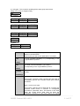
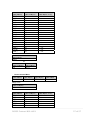
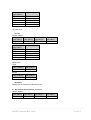
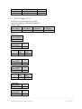
1.2
Change record
Revision
Date
Description
00
Jul-09
Initial Release
01
Jul-09
Changes in RS-232 protocol addendum
02
Feb-10
Changed RS-232 protocol (compatible with NSL-4601
firmware version V3.00 and higher)
Barco - NSL-4601 - User manual _______________________________________________________ 3
About the manual
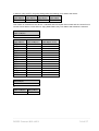
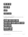
1.3
Notation convention
Following notations are applicable to this manual and should be respected
throughout the manual.
WARNING:
Warnings – presented in this manual, provide information, which if not adhered to, may result
in personal injury or death.
CAUTION:
Cautions – presented in this manual, provide information, which if not adhered to, may result
in damage to the equipment.
NOTE:
Notes – presented in this manual, provide information, which emphasize points, significant to
understand and operate the unit.
IMPORTANT:
Important – presented in this manual, provide information, which is important to highlight.
4 _______________________________________________________ Barco - NSL-4601 - User manual
Important notices, product safety precautions and package & storage
2
Important notices, product safety precautions and package & storage
2.1
Read carefully
IMPORTANT:
Please read the important notices and safety precautions, mentioned in the following paragraphs, carefully. They provide essential juridical and technical information about the purchased product.
2.2
Important notice
2.2.1
Copyright
© Barco n.v., All rights reserved.
The information contained herein is Barco confidential information. No part of
the information contained herein may be disclosed outside of the organization of
the recipient, its sub-contractors, and customers in any form or by any means
and/or stored in a database or retrieval system without the prior written consent
of Barco.
2.2.2
Technical accuracy notice
Although every attempt has been made to achieve technical accuracy in this
document, we assume no responsibility for errors that may be found. Our goal is
to provide you with the most accurate and usable documentation possible; if you
discover errors, please let us know.
2.2.3
Federal Communication Commission (FCC) notice
This equipment has been tested and found to comply with the limits of an FCC
class (refer to the technical specifications of the specific unit for more details
about the corresponding class). These limits are designed to provide reasonable
protection against harmful interference when the equipment is operated in a
commercial environment. This equipment generates, uses and can radiate radio
frequency energy and, if not installed and used in accordance with the
instruction manual, may cause harmful interference to radio communications.
Operation of this equipment in a residential area is likely to cause harmful
interference in which case the user will be required to correct the interference at
his own expense.
2.2.4
Warranty
During the warranty period, Barco n.v. will do all repairs free of charge
(material and labor). The faulty parts or units have to be shipped freight
prepaid to a Barco n.v. regional service center. Barco n.v. will pay the
freight charges when the repaired parts are shipped back to the
customer's site.
Damage of equipment due to improper use or negligence of the safety
Barco - NSL-4601 - User manual _______________________________________________________ 5
Important notices, product safety precautions and package & storage
precautions incorporated in this manual are not covered by this
warranty.
The warranty does not include the following:
2.2.5
•
Any hardware or software item procured from a source other than Barco n.v.
or their official agent or distributor and integrated by Customer or a third
party into Barco n.v. supplied equipment.
•
Any host or system configuration not explicitly supported by Barco n.v..
•
Consumables such as projector lamps, dust filters, ...
•
All software installed on the system, whether they are acquired from Barco
n.v. or a third party. An exception is made for software delivered by Barco
n.v. that would prove to be a cause for the malfunctioning of the hardware
covered under this Agreement.
•
If any payment remains outstanding from the Purchaser to the Seller.
•
Normal wear and tear, use under circumstances exceeding specifications,
abuse, unauthorized repair or alteration, lack of proper maintenance.
•
In the particular case of LCD displays, to the case of image retention phenomena (shadows, dark lines and other image artifacts), that may result
from a usage outside of the specification.
•
Any failures resulting from an accident, negligence (such as but not limited
to removing or deleting system files & licensed software product files), misuse, circuit failure or any change, damage due to fire, water, thunder or
lightning, power failure or fluctuation, disruption of communication lines or
due to force majeure, or any reason foreign to the equipment.
•
Any specific services or procedures, asked for by the Customer, related to
verification of repaired equipment.
•
If several failures occur which are excluded from warranty due to circumstances such as fire and if Barco n.v.’s understanding that these circumstances may result in damage to other hardware under agreement, then
Barco n.v. is entitled to terminate the contract. No fees will be paid back by
Barco n.v. in this case. Inspection of equipment will be required prior to the
continuation of this Agreement; the same terms and conditions as for the
inspection prior to the contract apply.
Trademarks
Brand and product names mentioned in this manual may be trademarks,
registered trademarks or copyrights of their respective holders. All brand and
product names mentioned in this manual serve as comments or examples and
are not to be understood as advertising for the products or their manufactures.
2.2.6
Open source license
This product contains software components released under an Open Source
license. A copy of the source code is available on request by contacting your
sales representative.
See appendix A for details.
6 _______________________________________________________ Barco - NSL-4601 - User manual
Important notices, product safety precautions and package & storage
2.3
Safety precautions
2.3.1
Earthing
WARNING:
The display unit must be earthed correctly. Verify that the power cable is plugged into a
standard 3-pin power outlet which is effectively earthed. When using extension cords, make
sure that they contain a grounded connection. If in doubt, contact a qualified electrician.
Ignoring this warning may lead to personal injury or death.
2.3.2
Electrical warnings and cautions
•
Do not power the unit with other input sources as specified in the technical
specifications.
•
Always power-down the unit before disconnecting the power cable.
•
Unplug the display unit from the power source when not in use.
IMPORTANT:
Immediately unplug if:
•
the power supply cord is damaged.
•
the unit has been dropped or the cabinet is damaged.
•
the unit does not operate normally by following the operation instructions.
WARNING:
Do not remove the cover without authorization. Removal of the cover by non-qualified
personnel can cause personal injury.
2.3.3
2.3.4
Environmental cautions
•
Do not use the display unit in a dusty or damp room.
•
Do not submit the display unit to heavy shocks and/or vibrations.
•
Do not cover the display unit while in operation to avoid overheating.
•
Do not expose to direct sunlight.
•
Do not use the display at extreme limits of temperature and humidity range.
Storage and operating limits are specified in the technical specifications of
the unit.
Requirement for dusty environments
The room in which the display unit is installed and operational must be dustfree. The room must comply with a dust class of 8 or better according to
ISO14644-1. If the room in which the display unit is installed does not comply
with the dust class stated above, please contact Barco to discuss possibilities to
protect the display unit against dust.
Barco - NSL-4601 - User manual _______________________________________________________ 7
Important notices, product safety precautions and package & storage
NOTE:
All construction, reconstruction, decoration activities must be completed before the installation
and operation of the product.
2.3.5
2.3.6
2.3.7
LCD screen
•
Do not apply pressure on the surface of the screen. If ‘waves’ are visible on
the screen below the pressing object (e.g. finger), the pressure is already
too high and the LCD may already break under these circumstances.
•
Do not hit the LCD screen with hard objects.
•
Do not rub the LCD screen with rough materials.
•
Do not touch the LCD screen with hard materials. Hard materials can cause
scratches on the surface of the LCD screen. Examples of hard material are:
fingernails, pencils, pens and styluses, wooden, plastic or metal objects.
•
While moving the display unit manually, hold the LCD screen away from your
body to avoid scratching the LCD screen.
•
Do not paste or stick objects with glues and/or adhesive tapes on the LCD
screen.
•
Wipe off water droplets or oil immediately. Ignoring this precaution could
lead to staining and/or discoloration of the LCD screen.
•
Do not expose the LCD screen to direct sunlight.
Cover
•
Do not place objects on the cover.
•
Do not spill fluids over the cover or the LCD screen.
•
Do not push objects into ventilation openings of the display unit.
Hazardous materials
WARNING:
The LCD panel is composed of multiple layers of glass and protective glass with a small amount
of liquid in between. Rough handling or dropping can cause the LCD panel to break. If any part
of the skin or body comes in direct contact with the liquid, immediately wash the affected areas
with plenty of water for at least 15 minutes. If any symptoms are present after washing, get
medical care.
2.3.8
Disposal information
WARNING:
The fluorescent tubes inside the backlight of the LCD contain a small amount of mercury that is
considered hazardous to a person’s health. Please follow local regulation or laws for disposal.
8 _______________________________________________________ Barco - NSL-4601 - User manual
Important notices, product safety precautions and package & storage
2.4
Package & storage
2.4.1
General
A safe transport of the units can only be guaranteed if the original undamaged
package is used for shipping. Handle with care when transporting.
Keep your original packaging. It is designed for this unit and is the ideal
protection during transportation.
2.4.2
Procedure in case of damages
All shipments should be opened and inspected for concealed damage or pilferage
as soon as possible after the arrival at destination. The shipping cartons should
be retained for the surveyor’s inspection and full and accurate reserves must be
made by a letter or a fax message.
Depending upon the used means of transport, the written protest is subject to
different time-rules:
•
by sea: the protest has to be issued against the captain and/or ship within 3
days of the delivery of the goods.
•
by road: the protest has to be issued against the last road-carrier within 7
days after delivery of the goods.
•
by air: the protest has to be issued against the air-carrier within 14 days
after delivery of the goods.
In all cases, a claim or potential claim should be reported as soon as possible
whether or not full documentation is immediately available.
After completion of all required steps, the claim should normally be finalized
within one month. For more information about the claims handling procedure,
contact Barco n.v.
2.4.3
Storage
It is best to store the display unit in its original packaging in a room that does
not exceed the storage conditions mentioned in the technical specification.
2.4.4
Electrolytic capacitors
The display unit needs to be powered on for a period of 24 hours at least once
every 2 years to allow internal electrolytic capacitors to be reformed. Failure to
do so may lead to compromised reliability.
Barco - NSL-4601 - User manual _______________________________________________________ 9
About the product
3
About the product
3.1
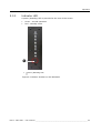
NSL-4601
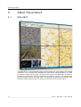
The NSL-4601 is a professional grade, narrow-bezel 46" LCD display with WXGA
resolution. The unit has been designed for tiled video wall applications in small
to medium-sized control rooms. As a tiled LCD solution the NSL-4601 is ideal for
Emergency Operations Centers, traffic and surveillance centers, and utilities and
process control rooms. The NSL-4601 is combining a space-saving design with
the best image quality around in terms of resolution and viewing angle.
10 ______________________________________________________ Barco - NSL-4601 - User manual
About the product
The Key features are:
Multiple sources, native resolution
In combination with a Barco display controller, the NSL-4601 allows to present
sources in native resolution without loss of content, or scaled. Multiple sources
(video, PC content or streaming video) can be presented and positioned
anywhere across the entire LCD wall.
Stable colors (Optional DCMS software)
The unit can be calibrated by means of Barco's display consistency management
software (DCMS). This ensures a correct white point and accurate grayscales.
Space saving
NSL-4601 video walls can be serviced from the front and the back. They require
no back room space at all, so they are ideally suited for control rooms where
space is limited. The high resolution of the tiled NSL-4601 video wall allows
operators to sit close by and monitor high-density information.
Front access
The unit has a smart, tiltable wall structure, which allows to easily service the
display wall’s electronics and cabling from the front. They require no back room
space at all.
Barco Wall Control Manager (BCM):
Barco’s NSL-4601 comes with Barco Wall Control Manager for video walls, a
software package that continuously supports worry-free operation of your video
wall. No more surprises, no unplanned or distracting maintenance interventions.
Wall configuration
The Wall Control Manager supports operators in setting up the wall
configuration. It also allows to choose the desired input, for individual modules,
the entire wall or for a group of modules.
Device monitoring
The Wall Control Manager will monitor and present the actual status of all
devices. For each module, health related information is presented on a status
indicator.
Control room management software (CMS):
Today's control rooms are complex networked environments handling an ever
increasing number of video and data sources. Efficient collaboration and
decisionmaking is only possible if there is easy and timely access to this
information.
In combination with Barco's control room management software (CMS), the
NSL-4601 video wall can significantly facilitate the decision-making and
collaboration process.
Barco's control room management suite provides operators and decision-makers
with easy access to information and allows them to connect to information, to
configure how it is displayed, and to collaborate in the most efficient way.
•
Barco's CMS software allows the operator to generate a preview of a multitude of sources (e.g. video, application screen data, external DVI feeds,
etc.) on his personal workstation.
Barco - NSL-4601 - User manual ______________________________________________________ 11
About the product
•
Once a personalized view has been created, the operator can send (push) it
to any video wall with pre-approved access.
•
CMS is also able to bring up (pull) sources that are displayed at remote display walls onto the local operator's screen.
Easy video and data integration
The NSL-4601 display is also compatible with Barco’s full range of display
controllers, including the PWS-101 workstation for multi-monitor personal
desktops and small to medium-sized video walls, Barco's TransForm series of
ultra-fast video wall display controllers and Barco's multiviewers which enable
operators to monitor their broadcast processes and visualize video content in
real-time from anywhere in the facility.
12 ______________________________________________________ Barco - NSL-4601 - User manual
Installation
4
Installation
4.1
Installation precautions
4.2
•
Keep the original packaging. It is designed for this unit and is the ideal protection during transport.
•
Allow adequate ventilation in case the configuration is built in a rack or a
console, so that the heat can properly dissipate.
•
For units where the power cable or connector is the primary means of
detaching the system from the power supply. One of the cable ends (or
power connector) should be easily accessible.
•
Make sure all units are disconnected from mains before connecting the signals.
•
The display unit must be earthed correctly, as described in the safety precautions paragraph.
•
Before connecting the unit to mains, check if the power source voltage corresponds to the mains voltage marked on the identification label on the display.
Specific installation precautions
•
The panel is foreseen with 2 handles at the rear side of the panel for easy
transportation. During installation or transportation, 2 people should lift an
edge of it by holding the handle.
•
Do not grip the front of the panel, the panel may get damaged when to
much pressure is applied. The display is slim and fragile, handle it carefully.
•
Do not incline the panel forward, the edge or bottom of the panel could be
damaged.
•
In case the panels need to be tiled on a wall, make sure the edges do not
collide with eachother during the installation, the edges could be damaged.
Barco - NSL-4601 - User manual ______________________________________________________ 13
Installation
4.3
Mounting procedure
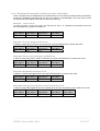
4.3.1
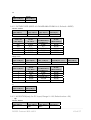
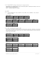
VESA compliant mounting solution
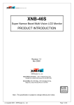
The NSL-4601 can be mounted on a device that is compliant to the VESA MIS-F
600x200mm or 600x400mm standard with M8x12 screws.
1
1
1
1
1
VESA MIS-F solution mounting holes M8 (4x)
Figure 1: VESA MIS-F compliant mounting
To attach the display to a device:
Attach the display firmly to the VESA comliant device using 4 screws M8x 12mm
IMPORTANT:
Use a device that is approved by VESA (according to the VESA MIL-F standard 600x200 or
600x400)
Use an arm that can support a weight of at least 30 kg or 66 lbs.
14 ______________________________________________________ Barco - NSL-4601 - User manual
Installation
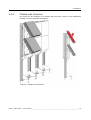
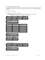
4.3.2
Tiltable wall structure
The units can be installed on a tiltable wall structure. Refer to the installation
manual for more detailed information.
Figure 2: Tiltable wall structure
Barco - NSL-4601 - User manual ______________________________________________________ 15
Installation
4.4
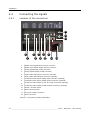
Connecting the signals
4.4.1
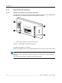
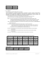
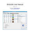
Location of the connectors
11
12
13
1
3
2
7
5
4
6
9
8
10
14
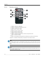
1
Digital Video Signal Input (DVI-D) connector
2
Digital Video Signal Output (DVI-D) connector
3
Analog Signal Input (SubD) connector
4
Analog Signal Output (SubD) connector
5
Super Video Signal Input connector (optional)
6
Super Video Signal Output connector (optional)
7
Composite Video Signal (CVBS) Input connector (optional)
8
Composite Video Signal (CVBS) Output connector (optional)
9
Component Video Signal (Y, Pb, Pr) Input connectors (optional)
10
Component Video Signal (CVBS) Output connectors (optional)
11
RS232 / I2C DIP switch
12
Monitor ID DIP switch
13
RS-232 In (SubD) connector
14
Power connector
Figure 3: Connector location NSL-4601
16 ______________________________________________________ Barco - NSL-4601 - User manual
Installation
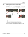
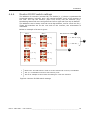
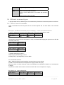
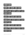
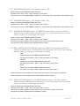
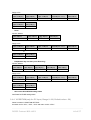
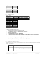
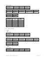
4.4.2
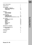
Connections for DVI and RS-232 with real DVI
loopthrough
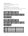
In this case, the master display or SET1 must be configured as master, the other
displays (SET2, 3 and 4) are to be configured as slave. The RS-232 data
transmission to the slave units is done by using the I²C EDID lines in the DVI
cable. See also the RS-232 DIP switch setting paragraph for the master/slave
configuration of the display.
SET 1: Master
1
SET 2: Slave
3
SET 4: Slave
2
4
SET 3: Slave
1
Digital Video Input signal (DVI source needs to be connected with set 1)
2
RS-232 In via RS cable (RS-232 cable needs to be connected with set 1)
3
DVI connections (DVI needs to be connected between each sets)
4
RS-232 data transmission (RS-232 data flows through DVI cable)
Figure 4: DVI and RS-232 connection with real DVI loopthrough (e.g. control
room with 4 units)
Barco - NSL-4601 - User manual ______________________________________________________ 17
Installation
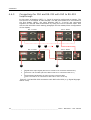
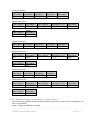
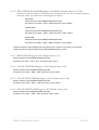
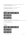
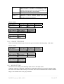
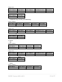
4.4.3
Connections for DVI and RS-232 with DVI to RS-232
loopthrough
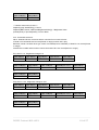
In this case, all displays (SET1, 2, 3 and 4) must be configured as master. The
DVI source is connected to each display. The RS-232 needs to be connected to
the first display (SET1), the other displays (SET 2, 3 and 4) are connected
together for RS-232 data tranmission by using the DVI to RS-232 cable. See
also the RS-232 DIP switch setting paragraph for the master/slave configuration
of the display.
SET 2: Master
SET 1: Master
1
2
3
1
SET 3: Master
SET 4: Master
1
1
1
Digital Video Input signal (DVI source needs to be connected with all sets)
2
RS-232 In via RS cable (RS-232 cable needs to be connected with set 1)
3
RS-232 data transmission is done via DVI to RS-232 cable
(DVI-out needs to be connected to RS-232 In of the next set)
Figure 5: DVI and RS-232 connection with DVI to RS-232 (e.g. Digital Signage
with 4 units)
18 ______________________________________________________ Barco - NSL-4601 - User manual
Installation
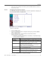
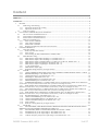
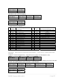
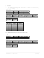
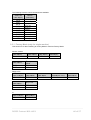
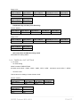
4.4.4
Monitor ID DIP switch settings
The address of a monitor (monitor ID) is a double (x, y) where x represents the
horizontal position (column) and y the vertical position (row) of the monitor in
the wall. The top left monitor (seen from front) has the address (0,0):
Numbering starts with zero and goes from left to right and from top to bottom.
The address is set in binary code via two 4-dip switches, one for x and one for y.
These dip switches are at the rear side of the monitor, see schematics of
interfaces.
Below an example of 4 sets is given:
SET 1
SET Monitor ID
SET 2
[X:0]
[X:1]
1
[ X : SET ID X ]
2
[Y:0]
[Y:0]
SET 4
SET 3
[ Y : SET ID Y ]
3
[X:0]
[X:1]
[Y:1]
[Y:1]
1
Monitor ID: the DIP switch is used to set the monitor ID via its X/Y coordinates
2
The X, Y coordinates need to be set to binary code
3
This is an example of the monitor ID setting for a set of 4 monitors
Figure 6: Monitor ID DIP switch settings
Barco - NSL-4601 - User manual ______________________________________________________ 19
Installation
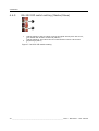
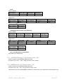
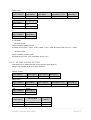
4.4.5
RS-232 DIP switch setting (Master/Slave)
1
2
1
2
switch setting for the set which receives the signal directly from the source,
not related with another monitor ID (Master)
switch setting for sets where the RS communication is done via the DVI
loopthrough (Slave)
Figure 7: RS-232 DIP switch setting
20 ______________________________________________________ Barco - NSL-4601 - User manual
Operation
5
Operation
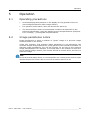
5.1
Operating precautions
5.2
•
Avoid displaying fixed patterns on the display for long periods of time to
avoid image persistence (after-image effects).
•
For optimum performance, allow 20 minutes for warm-up.
•
The unit should be used in environmental conditions as described in the
technical specification. Using the display beyond its specifications (temperature, humidity,…) will degrade its performance.
Image persistense notice
Image persistence is when a residual or “ghost” image of a previous image
remains visible on the screen.
Unlike CRT monitors, LCD monitors image persistence is not permanent, but
constant images being displayed for a long period of time should be avoided. To
alleviate image persistence, turn off the monitor for as long as the previous
image was displayed. For example, if an image was on the monitor for one hour
and a residual image remains, the monitor should be turned off for one hour to
erase the image.
NOTE:
As with all personal display devices, it is recommended to use a moving screen saver at regular
intervals whenever the screen is idle or to turn off the monitor when not in use.
Barco - NSL-4601 - User manual ______________________________________________________ 21
Operation
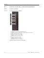
5.3
Function of primary controls and indicators
5.3.1
Primary controls
5.3.1.1
Location of primary controls
1
2
3
4
5
6
7
8
1
SOURCE: Selects the external input source
2
MENU: Activates the OSD menu, returns to the previous menu
3
LEFT: Function control in OSD
4
RIGHT: Function control in OSD
5
DOWN: Function control in OSD
6
UP: Function control in OSD
7
ENTER: confirms your choice
8
STANDBY: Power On / Off button
Figure 8: Primary controls of the NSL-4601
22 ______________________________________________________ Barco - NSL-4601 - User manual
Operation
5.3.2
Indicator LED
A power (Standby) LED is provided at the rear of the screen.
•
Green : normal operation
•
Red : standby mode
1
1
Power (Standby) LED
Figure 9: Indicator location on the NSL-4601
Barco - NSL-4601 - User manual ______________________________________________________ 23
Operation
5.3.3
Remote control
1
2
4
6
7
3
8
5
10
9
1
Power: Power On / Off button
2
Source: Selects the external input source
3
Select: confirms your choice
4
Up: Function control in OSD
5
Down: Function control in OSD
6
Left: Function control in OSD
7
Right: Function control in OSD
8
Menu: Activates the OSD menu, returns to the previous menu
9
Info: Information Display
10
Auto: Automatically adjust position & horizontal size, phase (PC mode only)
Figure 10: Location of the primary controls on the remote control
NOTE:
The remote control receiver is located below the power LED on the control panel at the rear
side of the display. Access via the remote control should be done from the rear side of the
panel.
NOTE:
Battery replacement should be done as depicted on the back side of the remote control. Use a
Lithium Battery CR2025 3V type.
24 ______________________________________________________ Barco - NSL-4601 - User manual
Operation
CAUTION:
Replace with the correct battery type, there is risk of explosion if the battery is replaced with
an incorrect type.
5.4
Adjusting display settings
5.4.1
Using the on screen display
5.4.1.1
Controls
Following controls are available on the monitor. There are 8 buttons:
Main function
Menu
Power
Power On / Off Button
Source
This button is used to active and deactivate source select OSD
Menu
This button has two functions:
• Active and deactivate OSD
• Return to previous menu
Select
When the OSD menu is popped up, if this button is pushed
The current menu will be selected
Up/Down
This button is used to navigate OSD menu
When the OSD main menu or sub-menu is popped up, if this button
is pushed, the active menu will move to upper/lower menu
Left/Right
This button is used to decrease the value of OSD menu.
After choosing the OSD menu and this button is pushed the value
of OSD will be decreased/increased.
Barco - NSL-4601 - User manual ______________________________________________________ 25
Operation
5.4.2
OSD overview functions
Main Menu
Sub Menu
Adjust parameter
Picture
Picture Mode
PC/DVI input: User, High, Middle, Low
Component/S-Video/CVBS input: User, Dynamic,
Standard, Movie, Mild
User
Contrast, Brightness, Sharpness (S-Video/AV/Component), Color(S-Video/AV/Component), Tint(S-Video/
AV)
Color Tone
User(Red, Green, Blue), Cool1(9300K),
Cool2(10000K), Normal(6500K), Warm1(6200K),
Warm2(5500K)
Size
PC/DVI input: Wide(16:9), 4:3
Component/S-Video/CVBS input: Wide(16:9), 4:3,
Zoom, Panorama, Zoom, 14:9
PC
Setup
Reset
Time
Multi
Auto Adjust
H/V Position, Clock, Clock phase
Phase
Adjust the PC Phase
H-Position
Adjust the PC input H-Position
V-Position
Adjust the PC input V-Position
Frequency
Adjust the PC input Frequency
Resets all user settings to default again
Clock
Adjust present time setting
On Timer
Turn on time setting
Off Timer
Turn off time setting
Language
English, Spanish, German, French
OSD Tone
Turn on/off OSD background blending
Key Lock
Turn on/off Key Lock function (Power key is not
locked)
Multi Function
H Cell Max
Adjust Horizontal Max Cell
V Cell Max
Adjust Vertical Max Cell
Cell Number
Adjust display number
H Gap Adjust
Adjust Horizontal Gap
V Gap Adjust
Adjust Vertical Gap
SET ID X
Display Set ID X (Read Only)
SET ID Y
Display Set ID Y (Read Only)
26 ______________________________________________________ Barco - NSL-4601 - User manual
Operation
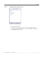
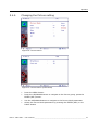
5.4.3
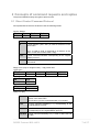
Selecting the Input Source
Figure 11: Input Source Menu
•
Press the SOURCE button
•
Navigate to the desired input source by using the UP/DOWN buttons
3
•
Following modes are available: PC – DVI – Component - S-Video - AV
Press the ENTER (SEL) button
Barco - NSL-4601 - User manual ______________________________________________________ 27
Operation
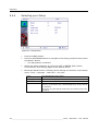
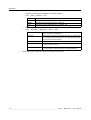
5.4.4
Selecting your Setup
Figure 12: Setup Menu
•
Press the MENU button
•
Press the UP/DOWN buttons to navigate to the Setup group and then presss
the SELECT button
3
The Setup Menu is selected
•
Select the Reset parameter by using the LEFT or ENTER (SEL) button.
This resets all user settings again to the default values.
•
Beside the Reset function, following other settings can be done via the Setup
menu: Time – Language – OSD Tone – Key Lock
Time
See Changing the Time value
Language
Different OSD languages can be chosen here
OSD Tone
Puts the OSD Tone On or Off
Key Lock
Via this parameter, the OSD keys (Menu key, Source key, Select key, Up and Down key, Left and Right key) can be Locked
or Unlocked
The power key and the IR control are not locked in Key Lock
On status
28 ______________________________________________________ Barco - NSL-4601 - User manual
Operation
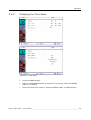
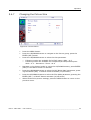
5.4.5
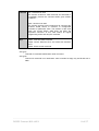
Changing the Time Value
Figure 13: Time Menu
•
Press the MENU button
•
Press the UP/DOWN buttons to select the Time group. Press the ENTER
(SEL) or UP button.
•
Select the Real Time mode by using the ENTER (SEL) or RIGHT button
Barco - NSL-4601 - User manual ______________________________________________________ 29
Operation
3
Following parameters can be adjusted: Clock – On Timer (on/off) – Off
Timer (off/on) – On Source (PC, DVI, Component, S-Video, AV)
Clock
Here the current time can be set (hh : mm)
On Timer
Here one can enter the ‘wake up’ time for the display
(display will be automatically powered up from its
Standby mode at the predefined On time). Therefore
the On Timer needs to be set in On mode.
Off Timer
Here one can enter the ‘off’ time for the display (display will be automatically put in Standby mode at the
predefined Off time)
Therefore the Off Timer needs to be set in On mode.
On Source
This parameter allows you to enter the source that
needs to be displayed at On time
30 ______________________________________________________ Barco - NSL-4601 - User manual
Operation
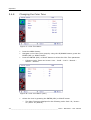
5.4.6
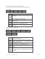
Changing the Picture setting
Figure 14: Picture Menu
Figure 15: Picture Menu (User Mode)
•
Press the MENU button
•
Press the UP/DOWN buttons to navigate to the Picture group, press the
ENTER (SEL) button.
•
Use the UP/DOWN buttons to navigate to the Picture Mode parameter
•
Select the Picture Mode parameter by pressing the ENTER (SEL) or the
RIGHT button
Barco - NSL-4601 - User manual ______________________________________________________ 31
Operation
3
3
Following modes are available for PC/DVI inputs:
User – High – Middle – Low
User
User can adjust Brightness and Contrast
High
Brightness and Contrast value is a rather high
Middle
Brightness and Contrast value is Normal
Low
Brightness and Contrast value is a rather low
Following modes are available for Component/S-Video/CVBS inputs:
User – Dynamic – Standard – Movie – Mild
User
Dynamic
•
User can adjust Brightness, Contrast, Color(Saturation), Tint(Hue), Sharpness
Brightness, Contrast and Sharpness value is a little high
=> Use this for dynamic picture viewing situations such
as moving picture as sports
Standard
Brightness and Contrast value is Normal
Movie
Brightness and Contrast value is a rather low
=> Use this for movie
Mild
Brightness and Contrast value is a rather low
=> Use this for smooth picture viewing situations
Press the Menu button to return to the previous menu
32 ______________________________________________________ Barco - NSL-4601 - User manual
Operation
5.4.7
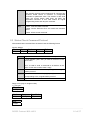
Changing the Picture Size
Figure 16: Picture Menu
•
Press the MENU button
•
Press the UP/DOWN buttons to navigate to the Picture group, press the
ENTER (SEL) button
•
Press the UP/DOWN buttons to select the Size parameter
3
3
Following modes are available for PC/DVI inputs: Wide – 4:3
Following modes are available for Component/S-Video/CVBS inputs:
Wide – 4:3 – Panorama – Zoom –14:9
•
Navigate to the desired mode by using the UP/DOWN buttons, press ENTER
(SEL) or the RIGHT button to activate
•
Press the UP/DOWN buttons to select the NR (Noise Rate) parameter, pressing the ENTER (SEL) or RIGHT button activates (on/off select)
•
Press the UP/DOWN buttons to select the Film Mode parameter, pressing the
ENTER (SEL) or RIGHT button activates (on/off select)
•
When finished the picture settings, press the MENU button to return to the
previous menu.
Barco - NSL-4601 - User manual ______________________________________________________ 33
Operation
5.4.8
Changing the Color Tone
Figure 17: Color Tone Menu
•
Press the MENU button
•
Navigate to the Color Tone group by using the UP/DOWN buttons, press the
ENTER (SEL) or RIGHT button
•
Press the ENTER (SEL) or RIGHT button to select the Color Tone parameter
3
Following Color Tones can be set: User – Cool2 – Cool1 – Normal –
Warm1 – Warm2
Figure 18: Color Tone Menu (User)
•
Select the User by pressing the ENTER (SEL) or RIGHT button
3
The Color Tones are displayed in the following order: Red: 50 / Green:
50 / Blue: 50 (default)
34 ______________________________________________________ Barco - NSL-4601 - User manual
Operation
•
5.4.9
When Color Tone settings are finished, press the MENU button to return to
the previous menu.
Changing the Multi Function
The multi menu settings menu settings are usefull for applications, displaying on
source as scaled image on a display wall.
Figure 19: Multi Menu
•
Press the MENU button
•
Press the UP/DOWN buttons to navigate to Multi group, press the ENTER
(SEL) or RIGHT button
•
Press the ENTER (SEL) or RIGHT button to select Multi Function
Following settings can be done:
3
•
H Cell Max, V Cell Max, Cell Number, H Gap Adjust, V Gap Adjust range:
1 to 20), SET ID X, SET ID Y
H Cell Max
Enter the number of displays in a row (range: 0 to 15).
V Cell Max
Enter the number of displays in a column (range: 0 to 15).
Cell Number
Enter the cell number. This is the location of the display in
the wall (starting from the top left monitor 0 and then from
left to right and top to bottom). (range: 0 to 255)
H Gap Adjust
The seam between adjacent monitors result in a small gap
between the sections of the image.
The horizontal gap can be adjusted via this parameter
(range: 0 to 20). See illustration below.
V Gap Adjust
The vertical gap can be adjusted via this parameter (range:
0 to 20). See illustration below.
SET ID X
Displays the X ID (set ID for RS-232 control) or horizontal
position of the monitor in the wall (range: 0 to 15).
SET ID Y
Displays the Y ID (set ID for RS-232 control) or vertical position of the monitor in the wall (range: 0 to 15).
Press UP or DOWN button to change the settings
Barco - NSL-4601 - User manual ______________________________________________________ 35
Operation
•
When settings are done, press the MENU button to return to the previous
menu.
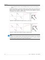
Below an illustration of a geometric pattern with (natural mode) and without cell
gap correction (full mode) is given. The small gaps can be removed by the socalled cell gap correction (image shift). The eye then perfoms a kind of
interpolation and realizes a smooth image:
Figure 20: Pattern without cell gap correction (full mode)
Figure 21: Pattern with cell gap correction (natural mode)
NOTE:
It depends on the displayed image if cell gap correction should be enabled or not: In case text
is displayed, cell gap correction results in missing (parts of) letters. For geometric patterns
(see picture above) cell gap correction results in a smooth picture.
36 ______________________________________________________ Barco - NSL-4601 - User manual
Maintenance
6
Maintenance
6.1
Cleaning precautions
6.2
•
Take care not to damage or scratch the LCD surface. Be carefull with rings,
jewellery and rough materials. Handle the LCD with care to avoid scratches.
•
Do not apply pressure on the LCD surface.
•
Do not apply or spray liquid directly to the LCD surface or cover as excess
liquid may cause damage to internal electronics. Instead apply the liquid to
the cleaning cloth.
•
Avoid dirt of fingerprints, oil, and fat staining on the LCD surface as they will
harm the LCD. Remove dirt by following the cleaning instructions below.
Cleaning instructions
Before cleaning:
•
Switch off the display unit.
•
Remove the power cord from the mains.
Cleaning the LCD screen:
•
Wipe the screen surface with a soft cleaning cloth.
•
To remove stains, use a damp cloth with non-aggressive cleaning products:
3
3
3
•
Do NOT use abrasive cleaning agents, glass cleaner or tissue paper.
Do NOT use alcohol/solvents at higher concentration > 5%.
Use non-aggressive cleaning products (water or a solution of distilled
water and IsoPropyl Alcohol).
Do not rub or push on the LCD screen. Rubbing with tissue can degrade the
performance of the LCD screen.
Cleaning the cover:
•
Use a soft cloth to remove dust. If necessary, a vacuum cleaner can be used
to clean the ventilation openings.
•
Use a damp cloth (if necessary with some mild detergent) to remove stains.
•
Do not use a scouring pad, or other tools that my scratch and damage the
cover.
•
Do not use strong detergents such as alcohol and thinner.
Barco - NSL-4601 - User manual ______________________________________________________ 37
Troubleshooting
7
Troubleshooting
No picture
•
Check whether the monitor is in standby mode. You can bring your monitor
out of standby by pressing the standby button.
•
Check if the power cord is inserted into wall power outlet.
•
Test the wall power outlet, plug another the power cord of another device
into the outlet where the monitor power cord was plugged in.
•
Check the picture contrast and brightness settings.
•
The signal cables should be completely connected to the unit.
•
Check all connectors for bent or pushed in pins.
•
Check that a valid input signal is applied.
Picture appears slowly after switching on
•
This is normal, the image is muted during the product startup process.
Please contact Barco, if the picture has not appeared after five minutes.
The signal is out of range
•
Adjust resolution.
•
Check it whether the signal cable is connected or loose.
•
Check the input source.
Screen color is unstable or single color
•
Check the signal cable.
•
Reinstall the PC video card.
38 ______________________________________________________ Barco - NSL-4601 - User manual
Specifications
8
Specifications
8.1
Electro-optical specifications
8.1.1
Panel
•
Active Matrix LCD (AM-LCD) – 8 bit/color
•
Super Pattern Vertical Alignment (SPVA) mode type, normally black
•
Incorporating amorphous silicon TFT.
8.1.2
Image specifications
8.1.2.1
Screen dimensions
•
Aspect ratio 16:9
•
Screen dimensions :
3
3
8.1.2.2
Screen specifications
•
16 777 216 colors – 256 gray scales
•
Typical viewing angle:
3
8.1.2.3
8.1.2.4
•
Horizontal: 178°
•
Vertical: 178°
Haze
8.1.2.7
40%
Surface hardness
•
8.1.2.6
Hard-coating (3H)
Light output
•
Maximum light output: 700 cd/m2
•
Typical light output: 500 cd/m2
Contrast ratio
•
Contrast Ratio in dark environment
3
3
8.1.2.8
Horizontal: ± 178°, Vertical: ± 178° @ CR >= 30
Viewing angle
•
8.1.2.5
1019 x 573.1 mm (40.1” x 22.6”)
1,168.4 mm (46”) diagonal
3000:1 (typ)
2500:1 (min)
Resolution
•
WXGA resolution: 1366 x 768 pixels
Barco - NSL-4601 - User manual ______________________________________________________ 39
Specifications
8.1.2.9
•
1 pixel is composed of 3 sub pixels R, G and B (RGB Vertical Stripe configuration)
•
pixel dimensions: 0.7455 mm x 0.7455 mm
Color temperature
•
Typical 10.000K in the center and perpendicular to the screen
•
Typical CIE coordinates are mentioned in the table below
x
8.1.2.10
8.1.2.11
Red
0,643
0,328
Green
0,271
0,599
Blue
0,143
0,0060
White
0,280
0,290
Response time
•
Rise time (black to white transition): 10 ms typ.
•
Fall time (white to black transition): 6 ms typ.
•
Gray to gray transition: 8 ms typ.
Luminance uniformity
•
White non-uniformity <= 25%
3
3
3
8.1.2.12
y
Non-uniformity = 100%(Lmax – Lmin) / Lmax
Luminance measured at 9 points evenly distributed on display
Measurement conforms to “VESA Flat Panel Display Measurements Standard Version 2.0”.
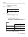
Pixel defects
Dot defect: when luminance of dot is brighter or darker then surrounded dots
Dot Defect Type Dot Defect Type
High Dot
Max
Random
5
Adjacent 2 dots
3
Adjacent 3 dots
1
Low Dot
Random
15
Off Dot
Random
10
Adjacent 2 dots
5
Adjacent 3 dots
3
Total amount of Dots
Minimum Distance between defects
20
High dot High dot
5mm
Off dot Off dot
Ignore
Dot Classification Method: the criteria of dot is defined by its brightness
Brightly visible dot comparing with background
STEP1: Start dot defect test at 0% Gray Pattern
40 ______________________________________________________ Barco - NSL-4601 - User manual
Specifications
•
If visible Go to 25% Gray Pattern
STEP2: At 25% Gray Pattern
•
If brightly visible
3
3
•
For Red/Blue, go to 50% Gray Pattern
For Green, go to 30% Gray Pattern
If invisible
3
No count
STEP3:
At 50% Gray Pattern for Red/Blue
At 30% Gray Pattern for Green
•
If brightly visible
3
•
High dot
If Invisible
3
Low Dot
Darkly visible dot comparing with background
•
Looks relatively dark at 100% Gray R, G ,B , White pattern.
3
Off dot
Minimum Distance between Dot Defects:
Minimum distance is direct distance (see picture)
Definition of Uniformity Defect:
While operating LCD panel, if certain area is remarkably brighter or darker.
However, extraneous substances which can be wiped out, like finger print,
particles, are not considered as a uniformity defect.
Spot and Linear Type Inspection:
Defect type
Criteria
Max
Spot Defect
0.1 < D <= 3 (mm)
10
0.01 < W <= 0.7 (mm) Criteria
15
Linear Defect
2 < L <= 15.0 (mm) Criteria
Total amount of Defects
20
Light Leakage:
There shall be no visible light around the edges of the screen.
Barco - NSL-4601 - User manual ______________________________________________________ 41
Specifications
Visual Appearance Defect Criteria:
Visible defect at non-operating LCD panel status.
Defect
Criteria
Max
Chassis Gap
Gap =< 1.5 (mm)
-
Spot Defect
0.1 < D <= 5.0 (mm)
10
Linear Defect
0.01 < W <= 0.7 (mm)
15
2.0 < L <= 20.0 (mm)
Total amount of Defects
20
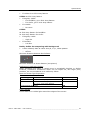
8.1.3
Input signal specifications
8.1.3.1
Signal input
Input
Specification
Min
PC(VGA)
/ DVI
Signal
Frequency
Separate
(H,V)
Sync (TTL)
Typ
Unit
Max
RGB
0.714
Vp-p
DVI
T.M.D.S
H
30.0
-
68.0
KHz
V
49
-
61
Hz
High
2.0
-
5.0
V
Low
0
-
0.8
DVI (PC to MNT)
Max length : 10
m
DVI (Set1 to Set2)
Max length : 1.8
m
Component
(optional)
YPbPr
VIDEO
(optional)
CVBS
(Composite)
Y
1.0
Pb/Pr
0.7
NTSC
0.71
4
Vp-p
0.28
6
PAL
Sync
Signal
0.7
0.3
S-VHS
(Y/C)
NTSC
Sync
Signal
1.0
0.28
6
PAL
Sync
Signal
1.0
0.3
CONTROL
RS-232C(PC to MNT)
Remark
Max length : 10
Sync
Signal
m
TBD
42 ______________________________________________________ Barco - NSL-4601 - User manual
Specifications
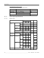
8.1.3.2
Supported resolutions
Resolution
8.1.3.3
Hfreq(kHz)
Vfreq(Hz)
PixelClk (MHz)
SVGA
800 x 600
37.879
60.317
40.000
XGA
1024 x 768
48.364
60.004
65.000
SXGA
1280 x 1024
63.981
60.020
108.00
WXGA
1360 x 768
47.700
60.000
84.700
1366 x 768
47.700
60.000
85.030
1366 x 768
47.700
50.000
84.238
1368 x 768
47.700
60.000
85.896
1368 x 768
47.700
50.000
84.330
Signal output
Output
Specification
Min
PC(VGA)
/ DVI
Signal
Typ
Unit
Max
RGB
0.714
DVI
T.M.D.S
H
30.0
-
68.0
KHz
V
49
-
61
Hz
Separate
(H,V)
Sync (TTL)
High
2.0
-
5.0
V
Low
0
-
0.8
Component
(optional)
YPbPr
Y
1.0
Pb/Pr
0.7
VIDEO
(optional)
CVBS
(Composite)
NTSC
0.71
4
Frequency
Vp-p
Vp-p
0.28
6
PAL
Sync
Signal
0.7
0.3
S-VHS
(Y/C)
NTSC
Sync
Signal
1.0
0.28
6
PAL
Sync
Signal
1.0
0.3
CONTROL
RS-232C
(‘n’ MNT to ‘n+1’ MNT)
Remark
Max sets : 16
Sync
Signal
sets
Barco - NSL-4601 - User manual ______________________________________________________ 43
Specifications
8.1.4
Human Machine Interface (HMI)
8.1.4.1
On-Screen Display (OSD)
•
The On-Screen Display (OSD) feature is the ability to display text on top of
the input signal.
•
This OSD information can be critical system information, on-line info, or
errors / warnings.
•
The OSD is accessible via the front control keys or the remote control.
•
This information is remotely accessible via a host processor with RS-232 terminal.
8.1.5
Power supply specification
8.1.5.1
110/220 Vac (47-53Hz, 57-63Hz) supply
8.1.5.2
8.1.5.3
•
Nominal voltage : 110 Vac or 220 Vac
•
Operates between 90 Vac – 144 Vac or 180 Vac – 264 Vac
•
Frequency range : 47 ~ 53 Hz or 57 ~ 63 Hz
Power consumption
•
Pmax: 300 W
•
Pmin: 5 W (Standby mode)
Safety
•
CE
: EN60950-1
•
Worldwide: IEC 60950-1
•
US: UL 60950-1
•
Canada: c-UL CSA C22.2 No.60950-1
•
China: CCC GB 4943-1995
8.1.6
Connectors
8.1.6.1
Input/Output connectors
8.1.6.2
•
Digital Video Signal Input/Output: DVI-D In/Out connector
•
Analog (R,G,B) Signal Input/Output: SubD 15p In/Out connector
•
Super Video (Y/C) Signal Input/Output (optional): S-Video In/Out
•
Composite Video Signal (CVBS) Input/Output (optional): BNC In/Out connector
•
Component Signal (Y, Pb, Pr) Input/Output (optional): BNC In/Out connector
(2 x 3)
Control connector
•
RS-232 control: SubD 9 p In connector
44 ______________________________________________________ Barco - NSL-4601 - User manual
Specifications
8.1.6.3
Power connector
•
110/220Vac, 300W power supply: Universal AC Input
8.2
Mechanical specifications
8.2.1
Dimensions
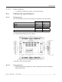
The unit dimensions and the unit weight are depicted in the table below:
mm
inch
Height
580.2
22.8
Width
1026.1
40.4
Depth
98
4.0
kg
lbs
29,8
65.7
Weight
The mechanical drawings are given below:
Figure 22: Dimensions NSL-4601
8.2.2
Components
•
Industrial extended temperature range components are used (including
plastic packaging).
Barco - NSL-4601 - User manual ______________________________________________________ 45
Specifications
8.2.3
Packing
•
Drop test according to Barco specifications is performed on the overall packing.
•
Unit packing is one packing responding to standards of international transport by air / sea / ground.
8.3
Environmental specifications
8.3.1
Storage temperature
8.3.2
8.3.3
•
High temp: +60°C (+140°F)
•
Low temp: -20°C (-4°F)
Operating temperature
•
High temp.: +40°C (+104°F)
•
Low temp.: +5°C (41°F)
Relative humidity operating
•
8.3.4
Relative humidity storage
•
8.3.5
Storage: 10 to 90% non-condensing
Random vibration
•
8.3.6
Operating: 20 to 80% non-condensing
0 - 0,0065 g²/Hz (5-500 Hz random, 1 hour/axes, 3 axis)
Requirement for dusty environments
The room in which the display unit is installed and operational must be dustfree. The room must comply with a dust class of 8 or better according to
ISO14644-1. If the room in which the display unit is installed does not comply
with the dust class stated above, please contact Barco to discuss possibilities to
protect the display unit against dust.
NOTE:
All construction, reconstruction, decoration activities must be completed before the installation
and operation of the product.
8.3.7
EMI /EMC
The units are designed to meet following standards:
•
USA:
3
FCC Class A (Part 15B)
46 ______________________________________________________ Barco - NSL-4601 - User manual
Specifications
•
Europe CE:
EN55022
Conducted Emission
EN55022
Radiated Emission
EN 61000-3-2
Conducted Emission Harmonic Currents
EN 61000-3-3
Voltage Changes Fluctuation and Flicker
EN55024
Susceptibility
EN 61000-4-2
ESD
EN 61000-4-3
ElectroMagnetic Field
EN 61000-4-4
Burst
EN 61000-4-5
Surges
EN 61000-4-6
Conducted Common Mode
EN 61000-4-8
Power Frequency Magnetic Field
EN 61000-4-11
Voltage Dips
8.4
Other specifications
8.4.1
MTBF
> 50.000 hours
8.4.2
Maintenance
8.4.2.1
MTTR
•
Less then 30 minutes.
8.4.2.2
Diagnostics
8.4.2.3
Use of maintenance equipment
8.4.2.4
Wear out items
8.4.2.5
•
The backlight lifetime is 50 000 hours/lamp @ 25°C.
•
The backlight is considered failed at 50% of the initial light output.
•
Lifetime is depending on the brightness setting during operation.
Workmanship
•
ccording to ANSI/IPC A-610A level II
Barco - NSL-4601 - User manual ______________________________________________________ 47
Abbreviations and acronyms
9
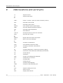
Abbreviations and acronyms
°C
Degrees Celsius
°F
Degrees Fahrenheit
A
ActEv
Actions + Events (name of a Barco software product)
AGC
Automatic Gain Control
ALC
Automatic Light Control
AMLCD
Active Matrix Liquid Crystal Display
ANSI
American National Standards Institute
APA
Automatic Phase Adjustment
AR
Anti Reflective
a-Si TFT
Amorphous Silicone Thin-Film Transistor
AWG
American Wire Gauge
B
BARCO
Belgian-American Radio Corporation
BCM
Barco wall Control Manager
C
CAN
Controller Area Network
CCFL
Cold Cathode Fluorescent Lamp
CCIR
Consulting Committee International
cd
candela
CE
Conducted Emissions, Conformity European (safety)
CIE
Commission International de l’Éclairage (Illumination)
CM
Console Mount
cm
centimeter
CMS
Control room Management Software
CoG
Combined sync on Green
CR
Contrast Ratio
CS
Combined Sync
CS
Conducted Susceptibility
CVBS
Composite Video Blanking Sync
D
DAC
Digital to Analog Converter
DC
Direct Current
DDC
Display Data Channel
48 ______________________________________________________ Barco - NSL-4601 - User manual
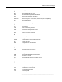
Abbreviations and acronyms
DM
Display Module
E
EBU
European Broadcast Union
EDID
Extended Display Identification Data
EIA
Electronic Industries Association
EMI / EMC
Electromagnetic Interference / Electromagnetic Compatibility
EN
European Norms
ESD
Electrostatic Discharge
F
FD
Full Duplex
FLIR
Forward Looking Infrared
FPDM
Flat Panel Display Measurements
G
GPI
General Purpose Interface
H
HD
Half Duplex
HDMI
High Definition Multimedia Interface
HDSDI
High Definition Serial Digital Interface
HE
Highly Efficient
HEA
High Efficiency Antireflective
HID
Human Interface Device
HMI
Human-Machine Interface
I
ICD
Interface Control Document
IEC
International Electrotechnical Commission
IP
Ingress Protection
ISO
International Standard Organization
ITO
Indium Tin Oxide
ITU
International Telecommunications Union
K
kg
kilogram
L
L
Luminance
LCD
Liquid Crystal Display
LFC
LCD Flicker Compensation
LRU
Line Replaceable Unit
LUT
Look Up Table
Barco - NSL-4601 - User manual ______________________________________________________ 49
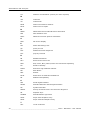
Abbreviations and acronyms
Lux
Measure of illumination (lumens per meter squared)
M
mm
millimeter
ms
milliseconds
MTBF
Mean-Time-Between-Failures
MTTR
Mean-Time-To-Repair
N
NEMA
National Electronics Manufacturers Association
NSL
Near Seamless LCD
NTSC
National Television Systems Committee
O
OSD
On-Screen Display
P
PAL
Phase Alternating Lines
ppi
pixels per inch
PVA
Patterned Vertical Alignment
PVC
polyvinyl chloride
R
RE
Radiated Emissions
RFU
Reserved for Future Use
RGB
Red, Green, Blue (letters/colors also referenced separately)
RH
Relative Humidity
RHDM
Reference High Definition Monitor
RM
Rack Mount
ROT
Rotator
RoHS
Restrictions of Hazardous Substances
RS
Radiated Susceptibility
S
SDI
Serial Digital Interface
SDSDI
Standard Definition Serial Digital Interface
SG
Symbol Generator
SMPTE
Society of Motion Picture and Television Engineers
SS
Separate Sync
STANAG
Standardization Agreement
SVGA
Super Video Graphics Array
SXGA
Super eXtended Graphics Array
T
TBC
To Be Confirmed
50 ______________________________________________________ Barco - NSL-4601 - User manual
Abbreviations and acronyms
TBD
To Be Defined
TBM
To be Measured
TBT
To Be Tested
TTL
Transistor Transistor Logic
U
UMD
Under Monitor Display
V
VDC
Volts Direct Current
VESA
Video Electronics Standards Association
VM
VESA Mount
W
W
Watt
Barco - NSL-4601 - User manual ______________________________________________________ 51
Addendum
10
Addendum
10.1
RS-232 protocol information
The addendum “RS232 Protocol NSL-4601” describes the RS-232 communication protocol
with the NSL-4601 display.
The protocol is applicable for NSL-4601 units with firmware version V3.00 and higher.
52 ______________________________________________________ Barco - NSL-4601 - User manual
RS232 Protocol NSL-4601
Document Version: 2010 02 16
Preface
Purpose of this Document
The purpose of this document is to provide a comprehensive description of the RS232 communication
protocol with the NSL-4601 panels.
Document Conventions
The following styles and conventions are used in this document:
Used to point out limitations or problems or open points, which are of crucial
importance.
Used to mark useful hints the reader should not oversee.
RS232 Protocol NSL-4601
2 of 57
Content
PREFACE ................................................................................................................................................................... 2
CONTENT .................................................................................................................................................................. 3
1
GENERAL ........................................................................................................................................................ 5
1.1
Addressing and chaining....................................................................................................................... 5
1.1.1
1.1.2
2
1.2
Com port settings .................................................................................................................................. 6
CONCEPTS OF COMMAND REQUESTS AND REPLIES ........................................................................................... 7
2.1
Direct Control Command Protocol....................................................................................................... 7
2.2
Value Adjust Command Protocol.......................................................................................................... 9
2.3
Status Check Command Protocol ....................................................................................................... 10
2.4
Different command types .................................................................................................................... 12
2.4.1
2.4.2
2.4.3
2.4.4
3
Dip Switch for Master slave setting .................................................................................................................. 5
Dip Switch for Device ID ................................................................................................................................. 5
Direct Control Commands .............................................................................................................................. 12
Value Adjust Commands ................................................................................................................................ 17
Status Check Commands ................................................................................................................................ 19
Broadcast Command to all devices in the serial chain .................................................................................... 25
COMMAND REFERENCE ................................................................................................................................. 26
3.1
Operation Modes ................................................................................................................................ 26
3.1.1
3.1.2
3.1.3
3.2
3.2.1
3.2.2
3.2.3
3.2.4
3.2.5
3.2.6
3.2.7
3.2.8
3.3
Read (only ONE SET selected)....................................................................................................................... 26
Power Control ................................................................................................................................................. 29
Source Setting (PC,DVI,COMPONENT,S-VIDEO,CVBS)........................................................................... 30
Multi Window setting .......................................................................................................................... 32
Multi Window Adjust H Max cell(Range 1~16, Default value = 1) ............................................................... 32
Multi Window Adjust V Max cell(Range 1~16, Default value = 1) ............................................................... 33
Multi Window Adjust Cell Number(Range 1~ H Max cell x V Max cell, Default value = 1) ........................ 33
Multi Window Adjust H Gap(Range 0~40, Default value = 0)....................................................................... 33
Multi Window Adjust V Gap(Range 0~40, Default value = 0)....................................................................... 33
1:1 Gap Adjust On/Off.................................................................................................................................... 33
Multi Window Adjust Apply .......................................................................................................................... 34
Read Multi setting status(only for single monitor).......................................................................................... 36
COLOR ............................................................................................................................................... 37
3.3.1
COLOR TEMPERATURE(USER-COOL2-COOL1-NORMAL-WARM2-WARM1, Default = COOL2) ... 37
3.3.2
BRIGHTNESS(Range 0~100, Default value = 50)......................................................................................... 37
3.3.3
CONTRAST(Range 0~100, Default value = 50) ............................................................................................ 38
3.3.4
HUE(Range 0~100, Default value = 50)......................................................................................................... 38
3.3.5
SATURATION(Range 0~100, Default value = 50)........................................................................................ 39
3.3.6
SHARPNESS(Range 0~100, Default value = 50) .......................................................................................... 39
3.3.7
SUB BRIGHTNESS(Range 0~75, MWCP default value is 30. But monitor’s default value is different as
current source. So if you want to know current value, you have to read single set value.) ............................................. 39
3.3.8
RED, GREEN, BLUE OFFSET(Range 0~80, MWCP default value is 40. But monitor’s default value is
different as current source. So if you want to know current value, you have to read single set value) ........................... 39
3.3.9
SUB CONTRAST(Range 0~75, MWCP default value is 30. But monitor’s default value is different as
current source. So if you want to know current value, you have to read single set value) .............................................. 39
3.3.10 RED, GREEN, BLUE GAIN(Range 0~80, MWCP default value is 40. But monitor’s default value is
different as current source. So if you want to know current value, you have to read single set value) ........................... 40
3.3.11 BACKLIGHT(Range 0~100, Default value = 72) .......................................................................................... 40
3.3.12 COLOR TONE RED(Range 0~100, Default value = 50) ............................................................................... 40
3.3.13 COLOR TONE GREEN(Range 0~100, Default value = 50).......................................................................... 40
3.3.14 COLOR TONE BLUE(Range 0~100, Default value = 50)............................................................................. 40
3.3.15 SAVE COLOR ............................................................................................................................................... 41
3.3.16 Read Color setting status(only for single monitor) ......................................................................................... 41
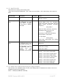
3.4
PICTURE ............................................................................................................................................ 42
3.4.1
PICTURE MODE (USER-HIGH/DYNAMIC-MIDDLE/STANDARD-LOW/MOVIE-MILD, Default =
MIDDLE(PC,DVI)/STANDARD(COMPONENT,S-VIDEO,AV))............................................................................... 42
3.4.2
PICTURE SIZE (WIDE-4:3-PANORAMA-ZOOM-14:9, Default = WIDE)................................................. 43
3.4.3
H-POSITION(only for PC input, Range 0~100, Default value = 50) ............................................................. 43
3.4.4
V-POSITION(only for PC input, Range 0~100, Default value = 50) ............................................................. 44
3.4.5
CLOCK(=Frequency)(only for PC input, Range 0~100, Default value = 50) ................................................ 45
RS232 Protocol NSL-4601
3 of 57
3.4.6
3.4.7
3.4.8
3.5
3.5.1
3.5.2
3.6
3.6.1
3.6.2
3.6.3
3.6.4
3.6.5
3.6.6
3.6.7
3.6.8
3.6.9
3.6.10
3.6.11
3.6.12
3.6.13
PHASE(only for PC input, Range 0~100, Default value = 50)....................................................................... 45
AUTO ADJUST(only for PC input) ............................................................................................................... 45
Read Picture setting status(only for single monitor) ....................................................................................... 45
IR/KEY ................................................................................................................................................ 45
Factory Mode (only for single monitor).......................................................................................................... 46
Read IR/KEY setting status(only for single monitor) ..................................................................................... 47
ETC ..................................................................................................................................................... 47
AGING MODE(OFF- FULL WHITE - FULL RED - FULL GREEN – FULL BLUE, Default = OFF) ....... 47
KEY LOCK(On/Off, Default = Off)............................................................................................................... 47
RESET ............................................................................................................................................................ 48
GAMMA SAVE ............................................................................................................................................. 49
FIRMWARE VERSION READ ..................................................................................................................... 49
DEVICE TYPE READ ................................................................................................................................... 50
MODE SETTING ........................................................................................................................................... 50
TIME SETTING ............................................................................................................................................. 51
TIMER ON / OFF SETTING ......................................................................................................................... 53
ON TIME SOURCE SETTING...................................................................................................................... 54
READ GAMMA DATA................................................................................................................................. 55
REQUEST and REPLY “NO SIGNAL” ........................................................................................................ 56
Read ETC setting status (only for single monitor).......................................................................................... 57
RS232 Protocol NSL-4601
4 of 57
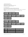
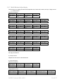
1 General
1.1 Addressing and chaining
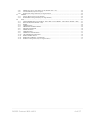
1.1.1 Dip Switch for Master slave setting
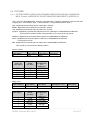
1.1.2 Dip Switch for Device ID
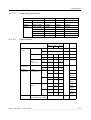
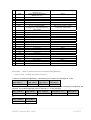
Mapping between dip switches and device addresses
The following table shows how the dip-switch settings are mapped to device addresses
Vertical(Y) Dip Switches
0
1
2
3
4
5
6
7
8
9
10
11
12
13
14
15
0
0
16
32
48
64
80
96
112
128
144
160
176
192
208
224
240
1
1
17
33
49
65
81
97
113
129
145
161
177
193
209
225
241
2
2
18
34
50
66
82
98
114
130
146
162
178
194
210
226
242
3
3
19
35
51
67
83
99
115
131
147
163
179
195
211
227
243
4
4
20
36
52
68
84
100
116
132
148
164
180
196
212
228
244
Horizontal (X) Dip Switches
5
6
7
8
9 10
5
6
7
8
9 10
21 22 23 24 25 26
37 38 39 40 41 42
53 54 55 56 57 58
69 70 71 72 73 74
85 86 87 88 89 90
101 102 103 104 105 106
117 118 119 120 121 122
133 134 135 136 137 138
149 150 151 152 153 154
165 166 167 168 169 170
181 182 183 184 185 186
197 198 199 200 201 202
213 214 215 216 217 218
229 230 231 232 233 234
245 246 247 248 249 250
RS232 Protocol NSL-4601
11
11
27
43
59
75
91
107
123
139
155
171
187
203
219
235
251
12
12
28
44
60
76
92
108
124
140
156
172
188
204
220
236
252
13
13
29
45
61
77
93
109
125
141
157
173
189
205
221
237
253
14
14
30
46
62
78
94
110
126
142
158
174
190
206
222
238
254
15
15
31
47
63
79
95
111
127
143
159
175
191
207
223
239
255
5 of 57
1.2 Com port settings
Protocol
Baud rate
Data Bits
Parity bit
Stop bit
Flow
control
RS232
9600bps
8 Bit
None
1 bit
None
RS232 Protocol NSL-4601
6 of 57
2 Concepts of command requests and replies
The protocol defines exactly two types of protocol units.
2.1 Direct Control Command Protocol
All requests that are send to the device have the following format:
Send to Monitor
Head
2 Byte
ID
3 Byte
Cmd
3 Byte
End
1 Byte
Head
All protocol units start with the same header-byte: “K:”
ID
3 Char identifier (“000”-“255”) is used for the device in the
serial chain.
“ALL” is used to send a command to all devices in the
chain. In this case monitor doesn’t reply.
Cmd
3 Char command Identifier corresponding to the “original
MWCP protocol”.
End
Type of command “.” for Set command and direct control
commands.
Reply to PC (Only for single monitor) – reply within 3sec.
1)Ack type1.
ID
3~5 Bytes
Cmd
4 Byte
Data
1~3 Bytes
Data End
2 Byte
Ack
1 Byte
2)Ack type2
ID
3~5 Bytes
Ack
1 Byte
3) Nack
ID
3~5 Bytes
Nack
1 Byte
4)Skip: no reply.
ID
3~5 Char identifier (“(0)”-“(255)”) is used for the selected
device in the serial chain.
This ID show you the correct destination of command.
Cmd
4 Char command Identifier(“***=”) corresponding to the
“original MWCP protocol”.
Data
1~3 Char command Identifier ( “(0)”-“(255)” )
corresponding to the “original MWCP protocol”.
Data End
2 Char command Identifier(“\r\n”) is used to define the end
of data.
RS232 Protocol NSL-4601
7 of 57
Ack/Nack
Ack : hexa 0x06 is used ,
The monitor received a valid command and was able to
immediately process the command within given timeout
conditions.
Nack : hexa 0x15 is used.
The monitor received correct head and ID command but
received invalid format or unknown or unsupported
command or parameter value. This answer is also send
when the current device state does not allow the
requested command. In this case search for logical
programming errors and retry the command.
Case1: Incorrect Head command.
Skip
Case2: Correct Head but ID is not match with monitor’s
set id.
Case3: All set control command.
Ack type1.
This kind of command isneed return value command.
Ack type2.
This kind of command is no need return value command so reply only set ID and Ack or
Nack.
RS232 Protocol NSL-4601
8 of 57
2.2 Value Adjust Command Protocol
All answers that are received from the device have the following format:
Send to Monitor
Head
2 Byte
ID
3 Byte
Cmd
3 Byte
Data
End
1 Byte
3 Byte
Head
All protocol units start with the same header-byte: “K:”
ID
3 Char identifier (“000”-“255”) is used for the device in the
serial chain.
“ALL” is used to send a command to all devices in the
chain. In this case monitor doesn’t reply.
Cmd
3 Char command Identifier corresponding to the “original
MWCP protocol”.
Data
1~3 Char command Identifier ( “(0)”-“(255)” )
corresponding to the “original MWCP protocol”.
Type of command “.” for Set command and direct control
commands.
End
Reply to PC (Only for single monitor)
1) Ack
ID
3~5 Bytes
Cmd
4 Byte
Data
1~3 Bytes
Data End
2 Byte
Ack
1 Byte
2) Nack
ID
3~5 Bytes
Nack
1 Byte
3) Skip: no reply.
ID
3~5 Char identifier (“(0)”-“(255)”) is used for the selected
device in the serial chain.
This ID show you the correct destination of command.
Cmd
4 Char command Identifier(“***=”) corresponding to the
“original MWCP protocol”.
Data
1~3 Char command Identifier ( “(0)”-“(255)” )
corresponding to the “original MWCP protocol”.
Data End
2 Char command Identifier(“\r\n”) is used to define the end
of data.
Ack/Nack
Ack : hexa 0x06 is used ,
The monitor received a valid command and was able to
immediately process the command within given timeout
conditions.
RS232 Protocol NSL-4601
9 of 57
Nack : hexa 0x15 is used.
The monitor received correct head and ID command but
received invalid format or unknown or unsupported
command or parameter value. This answer is also send
when the current device state does not allow the
requested command. In this case search for logical
programming errors and retry the command.
Case1: Incorrect Head command.
Skip
Case2: Correct Head but ID is not match with monitor’s
set id.
Case3: All set control command.
2.3 Status Check Command Protocol
All answers that are received from the device have the following format
Send to Monitor
Head
2 Byte
ID
3 Byte
Cmd
3 Byte
Data
3 Byte
End
1 Byte
Head
All protocol units start with the same header-byte: “K:”
ID
3 Char identifier (“000”-“255”) is used for the device in the
serial chain.
“ALL” is used to send a command to all devices in the
chain. In this case monitor doesn’t reply.
Cmd
3 Char command Identifier corresponding to the “original
MWCP protocol”.
Data
1~3 Char command Identifier ( “(0)”-“(255)” )
corresponding to the “original MWCP protocol”.
End
Type of command “?” for Status check commands.
Reply to PC (Only for single monitor)
1) Ack type1.
ID
3~5 Bytes
Cmd
4 Byte
Data
1~3 Bytes
Data End
2 Byte
Ack
1 Byte
RS232 Protocol NSL-4601
10 of 57
2) Ack type2 : This is used for updating all the same group menu items.
Reply to PC (Only for single monitor)
ID
3~5 Bytes
Cmd[0]
4 Byte
Data[0]
1~3 Bytes
Data End[0]
2 Byte
Cmd[1]
4 Byte
Data[1]
1~3 Bytes
Data End[1]
2 Byte
Data[n]
1~3 Bytes
Data End[n]
2 Byte
..
.
Cmd[n]
4 Byte
Ack
1 Byte
3) Nack
ID
3~5 Bytes
Nack
1 Byte
4) Skip : no reply.
ID
3~5 Char identifier (“(0)”-“(255)”) is used for the selected
device in the serial chain.
This ID show you the correct destination of command.
Cmd
or
4 Char command Identifier(“***=”) corresponding to the
“original MWCP protocol”.
Cmd[n]
Data
3~5 Char command Identifier ( “(0)”-“(255)” )
or
corresponding to the “original MWCP protocol”.
Data[n]
Data End
or
2 Char command Identifier(“\r\n”) is used to define the end
of data.
Data End[n]
Ack/Nack
Ack : hexa 0x06 is used ,
The monitor received a valid command and was able to
immediately process the command within given timeout
conditions.
Nack : hexa 0x15 is used.
The monitor received correct head and ID command but
received invalid format or unknown or unsupported
command or parameter value. This answer is also send
when the current device state does not allow the
requested command. In this case search for logical
RS232 Protocol NSL-4601
11 of 57
programming errors and retry the command.
Skip
Case1: Incorrect Head command.
Case2: Correct Head but ID is not match with monitor’s
set id.
Case3: All set control command.
2.4 Different command types
In principle there are four different types of commands they all make use of the same protocol unit format.
2.4.1 Direct Control Commands
These commands don’t have any data in the command request and can have data in the command
result.
Example1: Set Mode Command( Source change ) – return set id and ack/nack.
In order to change the input source the following PU is send to the device(set id = 000):
Head
ID
Cmd
Cmd end
(char-2Bytes)
(char-3Bytes) (char-3Bytes) (char-1Byte)
K:
000
SDV
.
This answer is retuned from the device(set id = 000). It indicates that changing the input source to DVI did
succeed(in case ack).
ID
ACK
(char-3~5Bytes)
(Hexa-1Byte)
(0)
or
ID
(char-3~5Bytes)
(0)
0x06
NACK
(Hexa-1Byte)
0x15
*** Monitor return source code ***
Didprintf("(%d)",GetSETID()); // Set Id
putchar(ACK); or putchar(NACK); // Ack or Nack.
Ack : Command excute ok.
Nack : Head and ID are correct but others command are not correct format.
If Head or ID commands are incorrect(format or range) monitor don’t reply.
Because monitor consider other type control command(ex auto calibration) if Head is not correct(format
or range).
And Monitor consider other monitor control command if ID is not correct(format or range).
Ex1) Set id = 10 , source change DVI.
Head
ID
Cmd
(char-2Bytes)
(char-3Bytes) (char-3Bytes)
K:
010
RS232 Protocol NSL-4601
SDV
Cmd end
(char-1Byte)
.
12 of 57
ID
(char-3~5Bytes)
ACK
(Hexa-1Byte)
(10)
0x06
Ex2) Set id = 100 , source change DVI.
Head
ID
Cmd
(char-2Bytes)
(char-3Bytes) (char-3Bytes)
K:
100
ID
(char-3~5Bytes)
ACK
(Hexa-1Byte)
(100)
0x06
SDV
*** Same format command list ***
No Comman
Description
d
1
2
PON / POF
SPC
3
4
5
6
7
8
9
10
11
12
13
14
15
16
17
18
19
20
SDV
SC1
SSV
SAV
ATU
RPW
RSO
RUP
RDN
RRT
RLT
REN
RMN
RAU
RIF
EIN
GSV
SCB
Cmd end
(char-1Byte)
.
No
Command
Description
Power On / Off
Source change to PC
21
22
SUC
Source change to DVI
Source change to COMPONENT
Source change to S-VIDEO
Source change to CVBS
Auto Adjust (only VGA input)
Remote control Power key
Remote control Source Key
Remote control Up key
Remote control Down key
Remote control Right key
Remote control Left key
Remote control Select key
Remote control Menu key
Remote control Auto key
Remote control Info key
Reset(Color)
Gamma LUT save
Save Contrast and Brightness data – Note1
23
24
25
26
27
28
29
30
31
32
33
34
35
36
37
38
39
40
NTN
NTF
FTN
FTF
GAN
GAF
Save Color tone Red/Green/Blue – Note1
Save Factory color control all items –
Note1
On Timer On
On Timer Off
Off Timer On
Off Timer Off
1:1 Gap adjust On – Note2
1:1 Gap adjust Off – Note2
SFC
Example2: Mode Select Command( Picture Mode ) – return set id , setting status and
ack/nack.
In order to increase the brightness by 1 the following PU is send to the device(set id = 000):
Head
ID
Cmd
Cmd end
(char-2Bytes)
(char-3Bytes) (char-3Bytes) (char-1Byte)
K:
000
PM0
.
This answer is retuned from the device(set id = 000). It indicates that changing the picture mode did
succeed. The updated picture mode is returned in 1 char data byte.
ID
Return Cmd
Data
Data End
ACK
(char-3~5Bytes)
(char-4Bytes)
(char-1Byte)
(char-2Bytes “\r\n”)
(Hexa-1Byte)
(0)
or
ID
(char-3~5Bytes)
(0)
PIM=
0
\r\n
0x06
NACK
(Hexa-1Byte)
0x15
RS232 Protocol NSL-4601
13 of 57
*** Monitor return source code ***
Didprintf("(%d)",GetSETID()); // Set Id
Didprintf("PIM=%d\r\n", GetPictureMode ()); // Picture Mode
putchar(ACK); or putchar(NACK); // Ack or Nack.
Ack : Command excute ok.
Nack : Head and ID are correct but others command is not correct format.
If Head or ID commands are incorrect(format or range) monitor don’t reply.
Because monitor consider other type control command(ex auto calibration) if Head is not correct(format
or range).
And Monitor consider other monitor control command if ID is not correct(format or range).
Ex1) Set id = 10 , change picture mode to USER mode.
Head
ID
Cmd
Cmd end
(char-2Bytes)
(char-3Bytes) (char-3Bytes) (char-1Byte)
K:
010
PM0
ID
(char-3~5Bytes)
Return Cmd
(char-4Bytes)
Data
(char-1~3Bytes)
(10)
PIM =
9
or
ID
(char-3~5Bytes)
(0)
.
Data End
(char-2Bytes “\r\n”)
\r\n
ACK
(Hexa-1Byte)
0x06
NACK
(Hexa-1Byte)
0x15
Ex2) Set id = 100 , change picture mode to USER mode.
Head
ID
Cmd
Cmd end
(char-2Bytes)
(char-3Bytes) (char-3Bytes) (char-1Byte)
K:
100
PM0
ID
(char-3~5Bytes)
Return Cmd
(char-4Bytes)
Data
(char-1~3Bytes)
(100)
PIM =
100
or
ID
(char-3~5Bytes)
(0)
.
Data End
(char-2Bytes “\r\n”)
\r\n
ACK
(Hexa-1Byte)
0x06
NACK
(Hexa-1Byte)
0x15
*** Same format command list ***
No Command
Description
1
CT0
Color temperature set to USER
2
CT1
Color temperature set to COOL1
3
CT2
Color temperature set to COOL2
4
CT3
Color temperature set to Normal
5
CT4
Color temperature set to WARM1
6
CT5
Color temperature set to WARM2
7
PM0
Picture Mode USER
RS232 Protocol NSL-4601
Return Cmd and Data
CRT=0
CRT=2
CRT=1
CRT=3
CRT=4
CRT=5
PIM=0
14 of 57
8
PM1
9
PM2
10
11
12
13
14
15
PM3
PM4
PS0
PS1
PS2
PS3
16
17
18
19
20
21
22
23
24
25
26
27
28
29
30
31
32
33
34
35
PS4
KLN / KLF
FMN
FMF
AGW
AGR
AGG
AGG
AGF
Picture Mode DYNAMIC/
HIGH(pc/dvi)
Picture Mode STANDARD/
MIDDLE(pc/dvi)
Picture Mode MOVIE/ LOW(pc/dvi)
Picture Mode MILD/ MIDDLE(pc/dvi)
Size set to WIDE(All source)
Size set to 4:3(All source)
Size set to ZOOM / WIDE(p/,dvi)
Size set to PANORAMA /
WIDE(pc/dvi) / ZOOM(component
1080i/1080p)
Size set to 14:9 / WIDE(pc/dvi)
Osd Key Lock On/Off
Factory Mode On
Factory Mode Off
Aging mode Full White
Aging mode Full Red
Aging mode Full Green
Aging mode Full Blue
Aging mode Off
NS0
On Source PC
NS1
On Source DVI
NS2
On Source COMPINENT
NS3
On Source S-VIDEO
NS4
On Source AV
MD0
Mode Auto
MD1
Mode 1368x768
MD2
Mode 1366x768
MD3
Mode 1360x768
MD4
Mode 12808x768
MD5
Mode 1024x768
PIM=1
PIM=2
PIM=3
PIM=4 / PIM=2(pc/dvi)
PIS=0
PIS=1
PIS=2 / PIS=0(pc/dvi)
PIS=3 / PIS=0(pc/dvi) / PIS=4
(component 1080i/1080p)
PIS=4 / PIS=0(pc/dvi)
KLC=1 / KLC=0
FMS=1
FMS=0
AGI=0
AGI=1
AGI=2
AGI=3
AGI=4
NSR=0
NSR=1
NSR=2
NSR=3
NSR=4
MDE=0
MDE=1
MDE=2
MDE=3
MDE=4
MDE=5
Example3: Value Increase Decrease Command( Brightness )
– return set id , setting value and ack/nack.
In order to increase the brightness by 1 the following PU is send to the device(set id = 000):
Head
ID
Cmd
Cmd end
(char-2Bytes)
(char-3Bytes) (char-3Bytes) (char-1Byte)
K:
000
BRU
.
This answer is retuned from the device(set id = 000). It indicates that increasing the brightness did
succeed. The updated brightness value is returned in 1~3 char data byte.
ID
Return Cmd
Data
Data End
ACK
(char-3~5Bytes)
(char-4Bytes)
(char-1~3Bytes)
(char-2Bytes “\r\n”)
(Hexa-1Byte)
(0)
or
ID
(char-3~5Bytes)
(0)
BRT=
54
\r\n
0x06
NACK
(Hexa-1Byte)
0x15
RS232 Protocol NSL-4601
15 of 57
***Monitor return source code ***
Didprintf("(%d)",GetSETID()); // Set Id
Didprintf("BRT=%d\r\n",GetPictureBrightnessValue()); // Brightness Value
putchar(ACK); or putchar(NACK); // Ack or Nack.
Ack : Command excute ok.
Nack : Head and ID are correct but others command is not correct format.
If Head or ID commands are incorrect(format or range) monitor don’t reply.
Because monitor consider other type control command(ex auto calibration) if Head is not correct(format
or range).
And Monitor consider other monitor control command if ID is not correct(format or range).
Ex1) Set id = 10 , Brightness change 8 to 9.
Head
ID
Cmd
(char-2Bytes)
(char-3Bytes) (char-3Bytes)
K:
010
BRU
ID
(char-3~5Bytes)
Return Cmd
(char-4Bytes)
Data
(char-1~3Bytes)
(10)
BRT=
9
or
ID
(char-3~5Bytes)
(0)
ACK
(Hexa-1Byte)
0x06
0x15
100
BRU
Return Cmd
(char-4Bytes)
Data
(char-1~3Bytes)
(100)
BRT=
100
(0)
Data End
(char-2Bytes “\r\n”)
NACK
(Hexa-1Byte)
ID
(char-3~5Bytes)
or
ID
(char-3~5Bytes)
.
\r\n
Ex2) Set id = 100 , Brightness change 99 to 100.
Head
ID
Cmd
(char-2Bytes)
(char-3Bytes) (char-3Bytes)
K:
Cmd end
(char-1Byte)
Cmd end
(char-1Byte)
.
Data End
(char-2Bytes “\r\n”)
\r\n
ACK
(Hexa-1Byte)
0x06
NACK
(Hexa-1Byte)
0x15
*** Same format command list ***
No Command
Description
1
MHU /
Multi window H Cell max 1step
MHD
Up/Down
2
MVU /
Multi window V Cell max 1step
MVD
Up/Down
3
DNU /
Multi window Cell No 1step Up/ Down
DND
4 HEU / HED Multi window H Gap(Edge) 1step Up/
Down
5 VEU / VED Multi window V Gap(Edge) 1step Up/
RS232 Protocol NSL-4601
Return Cmd
MHC=
MVC=
DNO=
MHG=
MVG=
16 of 57
6
7
8
9
10
11
12
13
14
15
16
17
18
19
20
21
22
23
24
25
26
27
28
29
30
31
32
CTU / CTD
BRU /
BRD
HUU /
HUD
STU / STD
SPU / SPD
BLU / BLD
SBU / SBD
ROU /
ROD
GOU /
GOD
BOU /
BOD
SCU / SCD
RGU /
RGD
GGU /
GGD
BGU /
BGD
HPU / HPD
VPU / VPD
CKU /
CKD
PHU / PHD
Down
Contrast 1step Up/Down
Brightness 1step Up/ Down
CON=
BRT=
Tint(Hue) 1step Up/ Down
TIN=
Saturation(Color) 1step Up/ Down
Sharpness 1step Up/ Down
Backlight 1step Up/ Down
Sub Brightness 1step Up/ Down
Red Offset 1step Up/Down
SAT=
SHA=
BLT=
SBR=
ROF=
Green Offset 1step Up/Down
GOF=
Blue Offset 1step Up/Down
BOF=
Sub Contrast 1step Up/Down
Red Gain 1step Up/Down
SCO=
RGN=
Green Gain 1step Up/Down
GGN=
Blue Gain 1step Up/Down
BGN=
H-Position 1step Up/Down(pc only)
V-Position 1step Up/Down(pc only)
Clock 1step Up/Down(pc only)
HPS=
VPS=
CLK=
Phase1step Up/Down(pc only)
PHS=
TIH=
TIM=
NTH=
NTM=
FTH=
FTM=
URE=
UGR=
UBL=
THU / THD
Time Hour Up/ Down
TMU / TMD
Time Minute Up/ Down
NHU / NHD
NMU / NMD
On Timer Hour Up/ Down
On Timer Minute Up/ Down
FHU / FHD
Off Timer Hour Up/ Down
FMU / FMD
Off Timer Minute Up/ Down
URU / URD
Color Tone Red Up/ Down)
UGU / UGD
Color Tone Green Up/ Down
UBU / UBD
Color Tone Blue Up/ Down
2.4.2 Value Adjust Commands
Example: Set Brightness
In order to set the brightness to 100 the following PU is send to the device:
Head
ID
Cmd
Data
Cmd end
(char-2Bytes) (char-3Bytes) (char-3Bytes)
(char-3Bytes)
(char-1Byte)
K:
000
BRT
054
.
This answer is retuned from the device. It indicates that increasing the brightness did succeed. The
updated brightness is returned in 1~3 char data byte.
ID
Return Cmd
Data
Data End
ACK
(char-3~5Bytes)
(char-4Bytes)
(char-1~3Bytes)
(char-2Bytes “\r\n”)
(Hexa-1Byte)
(0)
BRT=
54
\r\n
0x06
or
RS232 Protocol NSL-4601
17 of 57
ID
(char-3~5Bytes)
NACK
(Hexa-1Byte)
(0)
0x15
*** Monitor return source code ***
Didprintf("(%d)",GetSETID()); // Set Id
Didprintf("BRT=%d\r\n",GetPictureBrightnessValue()); // Brightness Value
putchar(ACK); or putchar(NACK); // Ack or Nack.
Ack : Command excute ok.
Nack : Head and ID are correct but others command is not correct format.
If Head or ID commands are incorrect(format or range) monitor don’t reply.
Because monitor consider other type control command(ex auto calibration) if Head is not correct(format
or range).
And Monitor consider other monitor control command if ID is not correct(format or range).
Ex1) Set id = 10 , Brightness change to 9.
Head
ID
Cmd
(char-2Bytes) (char-3Bytes) (char-3Bytes)
K:
010
BRT
Data
(char-3Bytes)
Cmd end
(char-1Byte)
009
.
ID
(char-3~5Bytes)
Return Cmd
(char-4Bytes)
Data
(char-1~3Bytes)
(10)
BRT=
9
or
ID
(char-3~5Bytes)
(0)
0x06
0x15
100
BRT
Data
(char-3Bytes)
Cmd end
(char-1Byte)
100
.
ID
(char-3~5Bytes)
Return Cmd
(char-4Bytes)
Data
(char-1~3Bytes)
(100)
BRT=
100
or
ID
(char-3~5Bytes)
(0)
ACK
(Hexa-1Byte)
NACK
(Hexa-1Byte)
Ex2) Set id = 100 , Brightness change to 100.
Head
ID
Cmd
(char-2Bytes) (char-3Bytes) (char-3Bytes)
K:
Data End
(char-2Bytes “\r\n”)
Data End
(char-2Bytes “\r\n”)
ACK
(Hexa-1Byte)
0x06
NACK
(Hexa-1Byte)
0x15
RS232 Protocol NSL-4601
18 of 57
*** Same format command list ***
No Command
Description(range)
1
MHC
Multi window H Cell max ( 1 ~ 16)
2
MVC
Multi window V Cell max ( 1 ~ 16)
3
DNO
Multi window Cell No ( 1 ~ 256)
4
MHG
Multi window H Gap(Edge) (0 ~ 40)
5
MVG
Multi window V Gap(Edge) ( 0 ~ 40)
6
CON
Contrast value Setting ( 0 ~ 100 )
7
BRT
Brightness value Setting( 0 ~ 100 )
8
TIN
Tint(Hue) Setting
(PC/DVI : 50 fixed ,COMPONENT/S-VIDEO/AV : 0 ~ 100 )
9
SAT
Saturation(Color) Setting
(PC/DVI/ COMPONENT : 50 fixed , S-VIDEO/AV : 0 ~ 100 )
10
SHA
Sharpness value Setting
(PC/DVI : 50 fixed ,COMPONENT/S-VIDEO/AV : 0 ~ 100 )
11
BLT
Back Light Setting ( 0 ~ 100)
12
SBR
Sub Brightness Setting ( 0 ~ 75)
13
ROF
Red Offset Setting ( 0 ~ 80)
14
GOF
Green Offset Setting ( 0 ~ 80)
15
BOF
Blue Offset Setting ( 0 ~ 80)
16
SCO
Sub Contrast Setting ( 0 ~ 75)
17
RGN
Red Gain Setting ( 0 ~ 80)
18
GGN
Green Gain Setting ( 0 ~ 80)
19
BGN
Blue Gain Setting ( 0 ~ 80)
20
HPS
H-Position Setting(Only for PC : 0 ~ 100 )
21
VPS
V-Position Setting(Only for PC : 0 ~ 100 )
22
CLK
Clock Setting(Only for PC : 0 ~ 100 )
23
PHS
Phase Setting(Only for PC : 0 ~ 100 )
24
TIH
Timer Hour(0 ~ 23)
25
TIM
Timer Minute(0 ~ 59)
26
NTH
On Timer Hour(0 ~ 23)
27
NTM
On Timer Minute(0 ~ 59)
28
FTH
Off Timer Hour(0 ~ 23)
29
FTM
Off Timer Minute(0 ~ 59)
30
URE
Color Tone Red Setting(0 ~ 100)
31
UGR
Color Tone Green Setting (0 ~ 100)
32
UBL
Color Tone Blue Setting (0 ~ 100)
Return Cmd
MHC=
MVC=
DNO=
MHG=
MVG=
CON=
BRT=
TIN=
SAT=
SHA=
BLT=
SBR=
ROF=
GOF=
BOF=
SCO=
RGN=
GGN=
BGN=
HPS=
VPS=
CLK=
PHS=
TIH=
TIM=
NTH=
NTM=
FTH=
FTM=
URE=
UGR=
UBL=
2.4.3 Status Check Commands
Example1: Get Brightness
In order to query the current brightness the following PU is send to the device:
Head
ID
Cmd
Cmd end
(char-2Bytes) (char-3Bytes) (char-3Bytes)
(char-1Byte)
K:
000
BRT
?
This answer is retuned from the device. It indicates that the request did succeed and the current
brightness (0x36) is returned in 1~3 char data byte.
ID
Return Cmd
Data
Data End
ACK
(char-3~5Bytes)
(char-4Bytes)
(char-1~3Bytes)
(char-2Bytes “\r\n”)
(Hexa-1Byte)
(0)
BRT=
54
\r\n
0x06
or
RS232 Protocol NSL-4601
19 of 57
ID
(char-3~5Bytes)
NACK
(Hexa-1Byte)
(0)
0x15
Ex1) Set id = 10 , current brightness request.
Head
ID
Cmd
(char-2Bytes) (char-3Bytes) (char-3Bytes)
K:
010
BRT
Cmd end
(char-1Byte)
?
Set id = 10 , current brightness(0x09) reply.
ID
Return Cmd
Data
(char-3~5Bytes)
(char-4Bytes)
(char-1~3Bytes)
(10)
or
ID
(char-3~5Bytes)
(0)
BRT=
9
\r\n
or
ID
(char-3~5Bytes)
(0)
0x06
0x15
100
BRT
Cmd end
(char-1Byte)
?
Set id = 10 , current brightness(0x64) reply
ID
Return Cmd
Data
(char-3~5Bytes)
(char-4Bytes)
(char-1~3Bytes)
(100)
ACK
(Hexa-1Byte)
NACK
(Hexa-1Byte)
Ex2) Set id = 100 , current brightness request.
Head
ID
Cmd
(char-2Bytes) (char-3Bytes) (char-3Bytes)
K:
Data End
(char-2Bytes “\r\n”)
BRT=
100
Data End
(char-2Bytes “\r\n”)
\r\n
ACK
(Hexa-1Byte)
0x06
NACK
(Hexa-1Byte)
0x15
*** Same format command list ***
No Command
Description
1
MHC
Multi window H Cell max value
2
MVC
Multi window V Cell max value
3
DNO
Cell No value
4
MHG
Multi window H Gap value
5
MVG
Multi window V Gap value
GAD
1:1 Gap Adjust setting status
6
CON
Contrast Value
7
BRT
Brightness value
8
SAT
Saturation(Color) value
9
TIN
Tint(Hue) value
10
SHA
Sharpness value
11
BLT
Backlight value
12
SBR
Sub Brightness value
13
ROF
Red Offset value
14
GOF
Green Offset value
15
BOF
Blue Offset value
16
SCO
Sub Contrast value
17
RGN
Red Gain value
18
GGN
Green Gain value
RS232 Protocol NSL-4601
20 of 57
19
20
21
22
23
24
25
26
27
28
BGN
PSZ
CRT
AGI
MDT
FWV
CSR
CPS
MLT
COL
29
30
PIC
ETC
Blue Gain value
Picture Size Setting status
Color temperature Setting status
Aging mode Setting status
Monitor Device Type Read.
Firmware Version Read
Current Source status
Current Power status
MHC,MVC,MHG,MVG,DNO
BRT,CON,TIN,SAT,SHA,CRT,BLT,S
BR,ROF,GOF,BOF,SCO,RGN,GGN,B
GN,URE,UGR,UBL
PIM,PIS,HPS,VPS,CLK,PHS
CPS,CSR,AGI.KLC,MDE,TIH,TUM,
NTH,NTM,NTI,FTH,FTM,FTI,NSR,
NSG,MDT
Example2: Get Menu Group setting status
In order to query the Multi set menu group setting status the following PU is send to the device:
Head
ID
Cmd
Cmd end
(char-2Bytes) (char-3Bytes) (char-3Bytes)
(char-1Byte)
K:
000
MLT
?
This answer is retuned from the device. It indicates that the request did succeed and the current Set Id,
HMaxCell, VMaxCell, H Gap, V Gap, Cell No and Ack/Nack is returned.
ID
(char-3~5Bytes)
(0)
Return Cmd
(char-4Bytes)
Data
(char-1~3Bytes)
MHC=
MVC=
MHG=
MVG=
DNO=
GAD=
2
2
1
1
2
1
Data End
(char-2Bytes “\r\n”)
\r\n
ACK
(Hexa-1Byte)
0x06
or
ID
(char-3~5Bytes)
(0)
NACK
(Hexa-1Byte)
0x15
RS232 Protocol NSL-4601
21 of 57
In order to query the Color set menu group setting status the following PU is send to the device:
Head
ID
Cmd
Cmd end
(char-2Bytes) (char-3Bytes) (char-3Bytes)
(char-1Byte)
K:
000
COL
?
This answer is returned from the device. It indicates that the request did succeed and the current Set Id,
Brightness, Contrast, Hue(Tint), Saturation(Color), Sharpness, Coor
Temperature,Sub Brightness, Red Offset, Green Offset, Blue Offset, Sub Contrast, Red Gain, Green
Gain, Blue Gain, Back Light and Ack/Nack is returned.
ID
(char-3~5Bytes)
(0)
Return Cmd
(char-4Bytes)
Data
(char-1~3Bytes)
BRT=
CON=
TIN=
SAT=
SHA=
CRT=
BLT=
SBR=
ROF=
GOF=
BOF=
SCO=
RGN=
GGN=
BGN=
URE=
UGR=
UBL=
50
50
50
50
50
1
72
24
35
25
26
34
27
28
17
50
50
50
Data End
(char-2Bytes “\r\n”)
\r\n
\r\n
\r\n
\r\n
\r\n
\r\n
\r\n
\r\n
\r\n
\r\n
\r\n
\r\n
\r\n
\r\n
\r\n
\r\n
\r\n
\r\n
ACK
(Hexa-1Byte)
0x06
or
ID
(char-3~5Bytes)
(0)
NACK
(Hexa-1Byte)
0x15
In order to query the Picture set group setting status the following PU is send to the device:
Head
ID
Cmd
Cmd end
(char-2Bytes) (char-3Bytes) (char-3Bytes)
(char-1Byte)
K:
000
PIC
RS232 Protocol NSL-4601
?
22 of 57
This answer is retuned from the device. It indicates that the request did succeed and the current Set Id,
Picture Mode, Picture Size, H Position(only PC), V Position(only PC), Clock (only PC), Phase(only PC),
and Ack/Nack is returned.
ID
(char-3~5Bytes)
(0)
Return Cmd
(char-4Bytes)
Data
(char-1~3Bytes)
PIM=
PIS=
HPS=
VPS=
CLK=
PHS=
2
0
50
50
50
50
Data End
(char-2Bytes “\r\n”)
\r\n
\r\n
\r\n
\r\n
\r\n
\r\n
ACK
(Hexa-1Byte)
0x06
or
ID
(char-3~5Bytes)
NACK
(Hexa-1Byte)
(0)
0x15
In order to query the IR/Key set group setting status the following PU is send to the device:
Head
ID
Cmd
Cmd end
(char-2Bytes) (char-3Bytes) (char-3Bytes)
(char-1Byte)
K:
000
RMC
?
This answer is retuned from the device. It indicates that the request did succeed and the current Factory
Mode status and Ack/Nack is returned.
ID
(char-3~5Bytes)
(0)
Return Cmd
(char-4Bytes)
Data
(char-1~3Bytes)
FMS=
0
Data End
(char-2Bytes “\r\n”)
\r\n
ACK
(Hexa-1Byte)
0x06
or
ID
(char-3~5Bytes)
(0)
NACK
(Hexa-1Byte)
0x15
RS232 Protocol NSL-4601
23 of 57
In order to query the ETC set group setting status the following PU is send to the device:
Head
ID
Cmd
Cmd end
(char-2Bytes) (char-3Bytes) (char-3Bytes)
(char-1Byte)
K:
000
ETC
?
This answer is retuned from the device. It indicates that the request did succeed and the current Set Id,
Current Power Status, Current Source, Aging Mode Status, Key Lock Status and Ack/Nack is returned.
ID
(char-3~5Bytes)
(0)
Return Cmd
(char-4Bytes)
Data
(char-1~3Bytes)
CPS=
CSR=
AGI=
KLC=
TIH=
TIM=
NTH=
NTM=
NTI=
FTH=
FTM=
FTI=
NSR=
MDE=
NSG=
1
1
0
0
23
59
23
59
0
23
59
0
1
1
0
Data End
(char-2Bytes “\r\n”)
\r\n
\r\n
\r\n
\r\n
\r\n
\r\n
\r\n
\r\n
\r\n
\r\n
\r\n
\r\n
\r\n
\r\n
\r\n
ACK
(Hexa-1Byte)
0x06
or
ID
(char-3~5Bytes)
(0)
NACK
(Hexa-1Byte)
0x15
RS232 Protocol NSL-4601
24 of 57
2.4.4 Broadcast Command to all devices in the serial chain
These commands are not addressed to an individual device in the chain but instead will be processed by
all devices. Broadcast commands will not give any replies or acknowledges. Thus only direct control
commands and value adjust commands can be send in this way.
Example: Power On all
In order to Power on all in the chain, the device-ID is set to “0”. Broadcast commands will not be
acknowledged with a reply from the device.
Head
(char-2Bytes)
ID
(char-3Bytes)
Cmd
(char-3Bytes)
Cmd end
(char-1Byte)
K:
ALL
PON
.
Example1: Source change to DVI all set
In order to change the input source to DVI all in the chain the following PU is send to the chain:
Head
ID
Cmd
Cmd end
(char-2Bytes) (char-3Bytes) (char-3Bytes)
(char-1Byte)
K:
ALL
SDV
.
Example2: Picture mode change to USER all set
In order to change the picture mode to USER all in the chain the following PU is send to the chain:
Head
ID
Cmd
Cmd end
(char-2Bytes) (char-3Bytes) (char-3Bytes)
(char-1Byte)
K:
ALL
PM0
.
Example3: Brightness increase all set
In order to increase the brightness all in the chain the following PU is send to the chain:
Head
ID
Cmd
Cmd end
(char-2Bytes) (char-3Bytes) (char-3Bytes)
(char-1Byte)
K:
ALL
BRU
.
Example4: Change the brightness value to 54(0x36) all set
In order to change the brightness value to 54(0x36) all in the chain the following PU is send to the chain:
Head
ID
Cmd
Data
Cmd end
(char-2Bytes) (char-3Bytes) (char-3Bytes)
(char-3Bytes)
(char-1Byte)
K:
ALL
BRT
RS232 Protocol NSL-4601
054
.
25 of 57
3 Command Reference
The command reference lists all commands, with a short explanation of their effect and details about the
command request protocol unit and the command reply protocol unit. The command reference is
organized.
3.1 Operation Modes
3.1.1 Read (only ONE SET selected)
-
Multi Control Menu (in case HMaxCell=2, VMaxCell=2, H Gap=1, H Gap=0, Cell No=2)
Send command to Monitor(current Brightness is 54(0x36))
Head
ID
Cmd
Cmd end
(char-2Bytes) (char-3Bytes) (char-3Bytes)
(char-1Byte)
K:
000
MLT
?
Reply to PC
ID
(char-3~5Bytes)
(0)
Return Cmd
(char-4Bytes)
Data
(char-1~3Bytes)
MHC=
MVC=
MHG=
MVG=
DNO=
GAD=
2
2
1
1
2
1
Data End
(char-2Bytes “\r\n”)
\r\n
ACK
(Hexa-1Byte)
0x06
or
ID
(char-3~5Bytes)
(0)
-
NACK
(Hexa-1Byte)
0x15
Color Control Menu
Head
ID
(char-2Bytes) (char-3Bytes)
Cmd
(char-3Bytes)
Cmd end
(char-1Byte)
K:
COL
?
000
Reply to PC
ID
(char-3~5Bytes)
(0)
RS232 Protocol NSL-4601
26 of 57
Return Cmd
(char-4Bytes)
Data
(char-1~3Bytes)
BRT=
CON=
TIN=
SAT=
SHA=
CRT=
BLT=
SBR=
ROF=
GOF=
BOF=
SCO=
RGN=
GGN=
BGN=
URE=
UGR=
UBL=
50
50
50
50
50
1
72
24
35
25
26
34
27
28
17
50
50
50
Data End
(char-2Bytes “\r\n”)
\r\n
\r\n
\r\n
\r\n
\r\n
\r\n
\r\n
\r\n
\r\n
\r\n
\r\n
\r\n
\r\n
\r\n
\r\n
\r\n
\r\n
\r\n
ACK
(Hexa-1Byte)
0x06
or
ID
NACK
(char-3~5Bytes)
(Hexa-1Byte)
(0)
-
0x15
Picture Control Menu
Head
ID
(char-2Bytes) (char-3Bytes)
Cmd
(char-3Bytes)
Cmd end
(char-1Byte)
K:
PIC
?
000
Reply to PC
ID
(char-3~5Bytes)
(0)
Return Cmd
(char-4Bytes)
Data
(char-1~3Bytes)
PIM=
PIS=
HPS=
VPS=
CLK=
PHS=
2
0
50
50
50
50
RS232 Protocol NSL-4601
Data End
(char-2Bytes “\r\n”)
\r\n
\r\n
\r\n
\r\n
\r\n
\r\n
27 of 57
ACK
(Hexa-1Byte)
0x06
or
ID
NACK
(char-3~5Bytes)
(Hexa-1Byte)
(0)
-
0x15
IR/Key Control Menu
Head
ID
(char-2Bytes) (char-3Bytes)
Cmd
(char-3Bytes)
Cmd end
(char-1Byte)
K:
RMC
?
000
Reply to PC
ID
(char-3~5Bytes)
(0)
Return Cmd
(char-4Bytes)
Data
(char-1~3Bytes)
FMS=
1
Data End
(char-2Bytes “\r\n”)
\r\n
ACK
(Hexa-1Byte)
0x06
or
-
ID
(char-3~5Bytes)
NACK
(Hexa-1Byte)
(0)
0x15
ETC Control Menu
Head
ID
(char-2Bytes) (char-3Bytes)
Cmd
(char-3Bytes)
Cmd end
(char-1Byte)
K:
ETC
?
000
Reply to PC
ID
(char-3~5Bytes)
(0)
Return Cmd
(char-4Bytes)
Data
(char-1~3Bytes)
CPS=
CSR=
AGI=
KLC=
TIH=
TIM=
1
1
0
0
23
59
RS232 Protocol NSL-4601
Data End
(char-2Bytes “\r\n”)
\r\n
\r\n
\r\n
\r\n
\r\n
\r\n
28 of 57
NTH=
NTM=
NTI=
FTH=
FTM=
FTI=
NSR=
MDE=
NSG=
23
59
0
23
59
0
1
1
0
\r\n
\r\n
\r\n
\r\n
\r\n
\r\n
\r\n
\r\n
\r\n
ACK
(Hexa-1Byte)
0x06
or
ID
(char-3~5Bytes)
NACK
(Hexa-1Byte)
(0)
0x15
-
3.1.2 Power Control
1) Power On/Off
-
All set in chain
Send to Monitor.
Head
ID
(char-2Bytes) (char-3Bytes)
K:
ALL
Cmd
(char-3Bytes)
Power Status
POF
PON
Off
On
Cmd
(char-3Bytes)
Cmd end
(char-1Byte)
PON
.
Cmd
(char-3Bytes)
Cmd end
(char-1Byte)
PON
.
No Reply to PC.
-
One set
Send to Monitor.
Head
ID
(char-2Bytes) (char-3Bytes)
K:
000
Cmd
(char-3Bytes)
Power Status
POF
PON
Off
On
RS232 Protocol NSL-4601
29 of 57
Reply to PC.
1)Ack
ID
(char-3~5Bytes)
ACK
(Hexa-1Byte)
(0)
0x06
2)Nack
ID
(char-3~5Bytes)
NACK
(Hexa-1Byte)
(0)
-
0x15
Group set
Repeat one set command to all selected set.
2) Get Power Status of one set
Send to Monitor.
Head
ID
(char-2Bytes) (char-3Bytes)
K:
000
Cmd
(char-3Bytes)
Cmd end
(char-1Byte)
CPS
?
Reply to PC.
1)Ack
ID
(char-3~5Bytes)
Cmd
(char-4Bytes)
Data
(char-1Byte)
(0)
CPS=
0
Data
(char-1Byte)
Power Status
0
1
Off
On
2)Nack
ID
(char-3~5Bytes)
Data End
(char-2Bytes “\r\n”)
\r\n
ACK
(Hexa-1Byte)
0x06
NACK
(Hexa-1Byte)
(0)
0x15
3.1.3 Source Setting (PC,DVI,COMPONENT,S-VIDEO,CVBS)
1) Source change
-
All set in chain
Send to Monitor.
Head
ID
(char-2Bytes) (char-3Bytes)
K:
ALL
Cmd
(char-3Bytes)
Cmd end
(char-1Byte)
SDV
.
RS232 Protocol NSL-4601
30 of 57
Cmd
(char-3Bytes)
Source
SPC
SDV
SC1
SSV
SAV
PC
DVI
COMPONENT
S-VIDEO
AV
No Reply to PC.
-
One set
Send to Monitor.
Head
ID
(char-2Bytes) (char-3Bytes)
K:
000
Cmd
(char-3Bytes)
Cmd end
(char-1Byte)
SDV
.
Cmd
(char-3Bytes)
Source
SPC
SDV
SC1
SSV
SAV
PC
DVI
COMPONENT
S-VIDEO
AV
Reply to PC.
1)Ack
ID
(char-3~5Bytes)
(0)
2)Nack
ID
(char-3~5Bytes)
(0)
-
ACK
(Hexa-1Byte)
0x06
NACK
(Hexa-1Byte)
0x15
Group set
Repeat one set command to all selected set.
3) Get Current Source Status of one set
Send to Monitor.
Head
ID
(char-2Bytes) (char-3Bytes)
K:
000
Cmd
(char-3Bytes)
Cmd end
(char-1Byte)
CPS
?
RS232 Protocol NSL-4601
31 of 57
Reply to PC.
1)Ack
ID
(char-3~5Bytes)
Cmd
(char-4Bytes)
Data
(char-1Byte)
(0)
CPS=
0
Data
(char-1Byte)
Source
0
1
2
3
4
2)Nack
ID
(char-3~5Bytes)
(0)
Data End
(char-2Bytes “\r\n”)
\r\n
ACK
(Hexa-1Byte)
0x06
PC
DVI
COMPONENT
S-VIDEO
AV
NACK
(Hexa-1Byte)
0x15
3.2 Multi Window setting
3.2.1 Multi Window Adjust H Max cell(Range 1~16, Default value = 1)
-
Up
Send to Monitor
Head
(char-2Bytes)
K:
Reply to PC
ID
(char-3~5Bytes)
(0)
or
ID
(char-3~5Bytes)
(0)
-
ID
(char-3Bytes)
Send Cmd
(char-3Bytes)
Cmd end
(char-1Byte)
000
MHU
.
Return Cmd
(char-4Bytes)
Data
(char-1~3Bytes)
MHU=
2
Data End
(char-2Bytes “\r\n”)
\r\n
ACK
(Hexa-1Byte)
0x06
NACK
(Hexa-1Byte)
0x15
Down
Send to Monitor
Head
(char-2Bytes)
K:
Reply to PC
ID
(char-3~5Bytes)
(0)
ID
(char-3Bytes)
Send Cmd
(char-3Bytes)
Cmd end
(char-1Byte)
000
MHD
.
Return Cmd
(char-4Bytes)
Data
(char-1~3Bytes)
MHD=
2
RS232 Protocol NSL-4601
Data End
(char-2Bytes “\r\n”)
\r\n
ACK
(Hexa-1Byte)
0x06
32 of 57
or
ID
NACK
(char-3~5Bytes)
(Hexa-1Byte)
(0)
-
0x15
Edit(Number key and then press Enter key)
Send to Monitor
Head
ID
(char-2Bytes) (char-3Bytes)
K:
000
Reply to PC
ID
(char-3~5Bytes)
(0)
Send Cmd
(char-3Bytes)
Data
(char-3Bytes)
Cmd end
(char-1Byte)
MHC
002
.
Return Cmd
(char-4Bytes)
Data
(char-1~3Bytes)
MHC=
2
Data End
(char-2Bytes “\r\n”)
\r\n
ACK
(Hexa-1Byte)
0x06
or
-
ID
(char-3~5Bytes)
NACK
(Hexa-1Byte)
(0)
0x15
Get current H Max Cell setting status
See Read Multi setting status.
3.2.2 Multi Window Adjust V Max cell(Range 1~16, Default value = 1)
Same format as Multi Window Adjust H Max cell
but send cmd is “MVU”, “MVD”, “MVC” and return cmd is “MVC=”.
3.2.3 Multi Window Adjust Cell Number(Range 1~ H Max cell x V Max cell, Default
value = 1)
Same format as Multi Window Adjust H Max cell
but send cmd is “DNU”, “DND”, “DNO” and return cmd is “DNO=” .
3.2.4 Multi Window Adjust H Gap(Range 0~40, Default value = 0)
Same format as Multi Window Adjust H Gap
but send cmd is “HEU”, “HED”, “MHG” and return cmd is “MHG =”.
3.2.5 Multi Window Adjust V Gap(Range 0~40, Default value = 0)
Same format as Multi Window Adjust H Gap
but send cmd is “VEU”, “VED”, “MVG” and return cmd is “MVG =”.
3.2.6 1:1 Gap Adjust On/Off
This function is for setting H/V Gap adjust Enable or Disable. If this function is enabled monitor does not
divide the display window but H/V gap can be adjusted. But if this function is disabled H/V gap can’t be
adjusted at HMaxCell = 1 and VMaxCell=1 status.
RS232 Protocol NSL-4601
33 of 57
3.2.7 Multi Window Adjust Apply
This function is for setting all multi set items(H Max Cell, V Max Cell, Cell No, H Gap, V Gap) at once.
1) All Set Control
Send PC to Monitor
Head
ID
(char-2Bytes) (char-3Bytes)
Send Cmd
(char-3Bytes)
Cmd end
(char-1Byte)
K:
ALL
VMB
.
Head
(char-2Bytes)
ID
(char-3Bytes)
Send Cmd
(char-3Bytes)
Data
(char-3Bytes)
Cmd end
(char-1Byte)
K:
ALL
MHC
002
.
Head
(char-2Bytes)
ID
(char-3Bytes)
Send Cmd
(char-3Bytes)
Data
(char-3Bytes)
Cmd end
(char-1Byte)
K:
ALL
MVC
002
.
Head
(char-2Bytes)
ID
(char-3Bytes)
Send Cmd
(char-3Bytes)
Data
(char-3Bytes)
Cmd end
(char-1Byte)
K:
ALL
DNO
001
.
Head
(char-2Bytes)
ID
(char-3Bytes)
Send Cmd
(char-3Bytes)
Data
(char-3Bytes)
Cmd end
(char-1Byte)
K:
ALL
MHG
000
.
Head
(char-2Bytes)
ID
(char-3Bytes)
Send Cmd
(char-3Bytes)
Data
(char-3Bytes)
Cmd end
(char-1Byte)
K:
ALL
MVG
000
.
Head
(char-2Bytes)
ID
(char-3Bytes)
Send Cmd
(char-3Bytes)
Cmd end
(char-1Byte)
K:
ALL
VMF
.
No reply from Monitor.
2) Group control
Repeat One set control to all selected set.
3) One set control
Send PC to Monitor
Head
ID
(char-2Bytes) (char-3Bytes)
K:
000
Send Cmd
(char-3Bytes)
Cmd end
(char-1Byte)
VMB
.
Reply Monitor to PC
ID
Return Cmd
(char-3~5Bytes)
(char-4Bytes)
(0)
VMT=
RS232 Protocol NSL-4601
Data
(char-1~3Bytes)
1
Data End
(char-2Bytes “\r\n”)
\r\n
ACK
(Hexa-1Byte)
0x06
34 of 57
or
ID
(char-3~5Bytes)
(0)
NACK
(Hexa-1Byte)
0x15
Send PC to Monitor
Head
ID
(char-2Bytes) (char-3Bytes)
K:
000
Send Cmd
(char-3Bytes)
Data
(char-3Bytes)
Cmd end
(char-1Byte)
MHC
002
.
Reply Monitor to PC
ID
Return Cmd
(char-3~5Bytes)
(char-4Bytes)
(0)
or
ID
(char-3~5Bytes)
(0)
MHC=
2
or
ID
(char-3~5Bytes)
(0)
000
Data
(char-3Bytes)
Cmd end
(char-1Byte)
MVC
002
.
MVC=
or
ID
(char-3~5Bytes)
(0)
Data
(char-1~3Bytes)
2
Data End
(char-2Bytes “\r\n”)
\r\n
ACK
(Hexa-1Byte)
0x06
NACK
(Hexa-1Byte)
0x15
000
Send Cmd
(char-3Bytes)
Data
(char-3Bytes)
Cmd end
(char-1Byte)
DNO
001
.
Reply Monitor to PC
ID
Return Cmd
(char-3~5Bytes)
(char-4Bytes)
(0)
0x06
Send Cmd
(char-3Bytes)
Send PC to Monitor
Head
ID
(char-2Bytes) (char-3Bytes)
K:
\r\n
ACK
(Hexa-1Byte)
0x15
Reply Monitor to PC
ID
Return Cmd
(char-3~5Bytes)
(char-4Bytes)
(0)
Data End
(char-2Bytes “\r\n”)
NACK
(Hexa-1Byte)
Send PC to Monitor
Head
ID
(char-2Bytes) (char-3Bytes)
K:
Data
(char-1~3Bytes)
DNO =
Data
(char-1~3Bytes)
1
Data End
(char-2Bytes “\r\n”)
\r\n
ACK
(Hexa-1Byte)
0x06
NACK
(Hexa-1Byte)
0x15
RS232 Protocol NSL-4601
35 of 57
Send PC to Monitor
Head
ID
(char-2Bytes) (char-3Bytes)
K:
000
Send Cmd
(char-3Bytes)
Data
(char-3Bytes)
Cmd end
(char-1Byte)
MHG
002
.
Reply Monitor to PC
ID
Return Cmd
(char-3~5Bytes)
(char-4Bytes)
(0)
or
ID
(char-3~5Bytes)
(0)
MHG=
2
or
ID
(char-3~5Bytes)
(0)
000
Data
(char-3Bytes)
Cmd end
(char-1Byte)
MVG
002
.
MVG=
or
ID
(char-3~5Bytes)
(0)
Data
(char-1~3Bytes)
2
Data End
(char-2Bytes “\r\n”)
\r\n
ACK
(Hexa-1Byte)
0x06
NACK
(Hexa-1Byte)
0x15
000
Send Cmd
(char-3Bytes)
Cmd end
(char-1Byte)
VMF
.
Reply Monitor to PC
ID
Return Cmd
(char-3~5Bytes)
(char-4Bytes)
(0)
0x06
Send Cmd
(char-3Bytes)
Send PC to Monitor
Head
ID
(char-2Bytes) (char-3Bytes)
K:
\r\n
ACK
(Hexa-1Byte)
0x15
Reply Monitor to PC
ID
Return Cmd
(char-3~5Bytes)
(char-4Bytes)
(0)
Data End
(char-2Bytes “\r\n”)
NACK
(Hexa-1Byte)
Send PC to Monitor
Head
ID
(char-2Bytes) (char-3Bytes)
K:
Data
(char-1~3Bytes)
VMT=
Data
(char-1~3Bytes)
0
Data End
(char-2Bytes “\r\n”)
\r\n
ACK
(Hexa-1Byte)
0x06
NACK
(Hexa-1Byte)
0x15
3.2.8 Read Multi setting status(only for single monitor)
This function is for updating current multi setting status of selected one monitor. This is not available in all
set or group selected.
See 3.1.1 Read (only ONE SET selected)
RS232 Protocol NSL-4601
36 of 57
3.3 COLOR
3.3.1 COLOR TEMPERATURE(USER-COOL2-COOL1-NORMAL-WARM2-WARM1,
Default = COOL2)
Send to monitor
Head
(char-2Bytes)
K:
Reply to PC
ID
(char-3~5Bytes)
(0)
or
ID
(char-3~5Bytes)
(0)
ID
(char-3Bytes)
Send Cmd
(char-3Bytes)
Cmd end
(char-1Byte)
000
CT0
.
Return Cmd
(char-4Bytes)
Data
(char-1~3Bytes)
CRT=
1
Data End
(char-2Bytes “\r\n”)
\r\n
ACK
(Hexa-1Byte)
0x06
NACK
(Hexa-1Byte)
0x15
Send Cmd
(char-3Bytes)
MODE
Reply
(CRT=*)
CT0
CT1
CT2
CT3
CT4
CT5
USER
COOL1
COOL2
NORMAL
WARM1
WARM2
0
1
2
3
4
5
3.3.2 BRIGHTNESS(Range 0~100, Default value = 50)
-
Up
Send to Monitor
Head
(char-2Bytes)
K:
Reply to PC
ID
(char-3~5Bytes)
(0)
or
ID
(char-3~5Bytes)
(0)
ID
(char-3Bytes)
Send Cmd
(char-3Bytes)
Cmd end
(char-1Byte)
000
BRU
.
Return Cmd
(char-4Bytes)
Data
(char-1~3Bytes)
BRU=
2
Data End
(char-2Bytes “\r\n”)
\r\n
ACK
(Hexa-1Byte)
0x06
NACK
(Hexa-1Byte)
0x15
RS232 Protocol NSL-4601
37 of 57
-
Down
Send to Monitor
Head
(char-2Bytes)
K:
Reply to PC
ID
(char-3~5Bytes)
(0)
ID
(char-3Bytes)
Send Cmd
(char-3Bytes)
Cmd end
(char-1Byte)
000
BRD
.
Return Cmd
(char-4Bytes)
Data
(char-1~3Bytes)
BRD=
2
Data End
(char-2Bytes “\r\n”)
\r\n
ACK
(Hexa-1Byte)
0x06
or
ID
NACK
(char-3~5Bytes)
(Hexa-1Byte)
(0)
-
0x15
Edit(Number key and then press Enter key)
Send to Monitor
Head
ID
(char-2Bytes) (char-3Bytes)
K:
000
Reply to PC
ID
(char-3~5Bytes)
(0)
Send Cmd
(char-3Bytes)
Data
(char-3Bytes)
Cmd end
(char-1Byte)
BRT
002
.
Return Cmd
(char-4Bytes)
Data
(char-1~3Bytes)
BRT=
2
Data End
(char-2Bytes “\r\n”)
\r\n
ACK
(Hexa-1Byte)
0x06
or
-
ID
(char-3~5Bytes)
NACK
(Hexa-1Byte)
(0)
0x15
Get current Brightness setting status
See Read Color setting status.
3.3.3 CONTRAST(Range 0~100, Default value = 50)
Same format as COLOR BRIGHTNESS SETTING.
but send cmd is “CTU”, “CTD”, “CON” and return cmd is “CON=”.
3.3.4 HUE(Range 0~100, Default value = 50)
Same format as COLOR BRIGHTNESS SETTING.
but send cmd is “TIU”, “TID”, “TIN” and return cmd is “TIN=”.
This function is for only COMPONENT,S-VIDEO,AV. This function can’t adjust at PC and DVI(fixed to 50).
RS232 Protocol NSL-4601
38 of 57
3.3.5 SATURATION(Range 0~100, Default value = 50)
Same format as COLOR BRIGHTNESS SETTING.
but send cmd is “STU”, “STD”, “SAT” and return cmd is “SAT=”.
This function is for only COMPONENT,S-VIDEO,AV. This function can’t adjust at PC and DVI(fixed to 50).
3.3.6 SHARPNESS(Range 0~100, Default value = 50)
Same format as COLOR BRIGHTNESS SETTING.
but send cmd is “SPU”, “SPD”, “SHA” and return cmd is “SHA=”.
This function is for only COMPONENT,S-VIDEO,AV. This function can’t adjust at PC and DVI(fixed to 50).
3.3.7 SUB BRIGHTNESS(Range 0~75, MWCP default value is 30. But monitor’s
default value is different as current source. So if you want to know current
value, you have to read single set value.)
Same format as COLOR BRIGHTNESS SETTING.
but send cmd is “SBU”, “SBD”, “SBR” and return cmd is “SBR=”.
This function is used to adjust color only factory line or service. Don’t open to normal user.
This function is used to adjust picture brightness offset of scaler.
3.3.8 RED, GREEN, BLUE OFFSET(Range 0~80, MWCP default value is 40. But
monitor’s default value is different as current source. So if you want to know
current value, you have to read single set value)
-
RED
Same format as COLOR BRIGHTNESS SETTING.
but send cmd is “ROU”, “ROD”, “ROF” and return cmd is “ROF=”.
-
GREEN
Same format as COLOR BRIGHTNESS SETTING.
but send cmd is “GOU”, “GOD”, “GOF” and return cmd is “GOF=”.
-
BLUE
Same format as COLOR BRIGHTNESS SETTING.
but send cmd is “BOU”, “BOD”, “BOF” and return cmd is “BOF=”.
These functions are used to adjust color only factory line or service. Don’t open to normal user.
These functions are used to adjust picture Red/Green/Blue offset of scaler.
3.3.9 SUB CONTRAST(Range 0~75, MWCP default value is 30. But monitor’s
default value is different as current source. So if you want to know current
value, you have to read single set value)
Same format as COLOR BRIGHTNESS SETTING.
but send cmd is “SCU”, “SCD”, “SCO” and return cmd is “SCO=”.
This function is used to adjust color only factory line or service. Don’t open to normal user.
This function is used to adjust picture contrast gain of scaler.
RS232 Protocol NSL-4601
39 of 57
3.3.10 RED, GREEN, BLUE GAIN(Range 0~80, MWCP default value is 40. But
monitor’s default value is different as current source. So if you want to know
current value, you have to read single set value)
-
RED GAIN
Same format as COLOR BRIGHTNESS SETTING.
but send cmd is “RGU”, “RGD”, “RGN” and return cmd is “RGN=”.
-
GREEN GAIN
Same format as COLOR BRIGHTNESS SETTING.
but send cmd is “GGU”, “GGD”, “GGN” and return cmd is “GGN=”.
-
BLUE GAIN
Same format as COLOR BRIGHTNESS SETTING.
but send cmd is “BGU”, “BGD”, “BGN” and return cmd is “BGN=”.
These functions are used to adjust color only factory line or service. Don’t open to normal user.
These functions are used to adjust picture Red/Green/Blue gain of scaler.
3.3.11 BACKLIGHT(Range 0~100, Default value = 72)
Same format as COLOR BRIGHTNESS SETTING.
but send cmd is “BLU”, “BLD”, “BLT” and return cmd is “BLT=”.
3.3.12 COLOR TONE RED(Range 0~100, Default value = 50)
Same format as COLOR BRIGHTNESS SETTING.
but send cmd is “URU”, “URD”, “URE” and return cmd is “URE=”.
3.3.13 COLOR TONE GREEN(Range 0~100, Default value = 50)
Same format as COLOR BRIGHTNESS SETTING.
but send cmd is “UGU”, “UGD”, “UGR” and return cmd is “UGR=”.
3.3.14 COLOR TONE BLUE(Range 0~100, Default value = 50)
Same format as COLOR BRIGHTNESS SETTING.
but send cmd is “UBU”, “UBD”, “UBL” and return cmd is “UBL=”.
RS232 Protocol NSL-4601
40 of 57
3.3.15 SAVE COLOR
This function is for saving current setting value.
”SCB” Save Contrast and Brightness, “SUC” Save color tone R/G/B , “SFC” Save factory color control all
items.
Save Concept
Description
Command
Items
Auto
Saved whenever power
off
No need
Power On/Off,
Changed value is saved
to EEPROM at once
when value is changed
by osd menu or MWCP
command.
No need
Immediately
items
saved
Set ID X, Set ID Y
-
Picture Menu -
Picture Mode, Color, Tint, Sharpness,
Color Tone mode, Size, Mode, NR, Film
Mode, Phase, H-Position, V-Position,
Frequency
-
Set up Menu –
Clock, On Timer, Off Timer, On Source,
Language, OSD Tone, Key Lock
-
Multi Menu –
H Cell Max, V Max Cell, Cell Number,
H Gap Adjust, V Gap Adjust,
1:1 Gap Adjust
-
Factory Mode –
Last Power, Aging Mode, DLC, Model,
Gamma Data
Need save command
items
Changed value is saved
to EEPROM when save
command is received. Or
“SCB”
changed value is saved
to EEPROM after 2
minutes
from
last
changed
if
save
command is not received.
“SUC”
Contrast,
Brightness
Color Tone > Red,
Color Tone > Green,
Color Tone > Blue
“SFC”
Factory > Color Control > Sub Brightness,
Factory > Color Control >Red Offset,
Factory > Color Control >Green Offset,
Factory > Color Control >Blue Offset,
Factory > Color Control > Sub Contrast,
Factory > Color Control >Red Gain,
Factory > Color Control >Green Gain,
Factory > Color Control >Blue Gain,
Factory > Color Control >Backlight,
3.3.16 Read Color setting status(only for single monitor)
This function is for updating current all color menu setting status of selected one monitor. This is not
available in all set or group selected.
See 3.1.1 Read (only ONE SET selected)
RS232 Protocol NSL-4601
41 of 57
3.4 PICTURE
3.4.1 PICTURE MODE (USER-HIGH/DYNAMIC-MIDDLE/STANDARD-LOW/MOVIEMILD, Default = MIDDLE(PC,DVI)/STANDARD(COMPONENT,S-VIDEO,AV))
User : User can adjust Brightness, Contrast, Color(Saturation), Tint(Hue), Sharpness value as uaer want
to adjust.(Tint – at S-Video/AV input , Color/Sharpness – Component/S-Video/AV input )
High : Brightness and Contrast value is a little high in PC/DVI.
Middle : Brightness and Contrast value is Normal in PC/DVI.
Low : Brightness and Contrast value is a little low in PC/DVI.
Dynamic : Brightness, Contrast and Sharpness value is a little high in COMPONENT/S-VIDEO/AV.
This is good for dynamic picture viewing situation such moving picture as sports.
Standard : Brightness and Contrast value is Normal in COMPONENT/S-VIDEO/AV.
Movie : Brightness and Contrast value is a little low in COMPONENT/S-VIDEO/AV.
This is good for movie.
Mild : Brightness and Contrast value is a little low in COMPONENT/S-VIDEO/AV.
This is good for smooth picture viewing situation.
Send to monitor
Head
(char-2Bytes)
K:
ID
(char-3Bytes)
Send Cmd
(char-3Bytes)
Cmd end
(char-1Byte)
000
PM0
.
Send Cmd
(char-3Bytes)
MODE
(PC, DVI)
MODE
(COMPONEN
T,SVIDEO,AV)
PM0
PM1
PM2
PM3
PM4
USER
HIGH
MIDDLE
LOW
MIDDLE
USER
DYNAMIC
STANDARD
MOVIE
MILD
Reply to PC
ID
(char-3~5Bytes)
Return Cmd
(char-4Bytes)
Data
(char-1Byte)
PIM=
0
(0)
Data
(char-1Byte)
0
1
2
3
4
MODE
(PC, DVI)
MODE
(COMPONEN
T,SVIDEO,AV)
USER
HIGH
MIDDLE
LOW
MIDDLE
USER
DYNAMIC
STANDARD
MOVIE
MILD
RS232 Protocol NSL-4601
Data End
(char-2Bytes “\r\n”)
\r\n
ACK
(Hexa-1Byte)
0x06
42 of 57
Or
ID
(char-3~5Bytes)
NACK
(Hexa-1Byte)
(0)
0x15
3.4.2 PICTURE SIZE (WIDE-4:3-PANORAMA-ZOOM-14:9, Default = WIDE)
Send to monitor
Head
(char-2Bytes)
K:
ID
(char-3Bytes)
Send Cmd
(char-3Bytes)
Cmd end
(char-1Byte)
000
PS0
.
Send Cmd
(char-3Bytes)
MODE
(PC, DVI)
MODE
(COMPONENT,
S-VIDEO,AV)
MODE
(Multi window)
PS0
PS1
PS2
PS3
PS4
WIDE
4:3
WIDE
WIDE
WIDE
WIDE
4:3
PANORAMA
ZOOM
14:9
WIDE
WIDE
WIDE
WIDE
WIDE
Reply to PC
ID
(char-3~5Bytes)
Return Cmd
(char-4Bytes)
Data
(char-1~3Bytes)
PIS=
0
(0)
Data
(char-1~3Bytes)
0
1
2
3
4
or
ID
(char-3~5Bytes)
(0)
Data End
(char-2Bytes “\r\n”)
\r\n
MODE
(PC, DVI)
MODE
(COMPONENT,
S-VIDEO,AV)
MODE
(Multi window)
WIDE
4:3
WIDE
WIDE
WIDE
WIDE
4:3
PANORAMA
ZOOM
14:9
WIDE
WIDE
WIDE
WIDE
WIDE
ACK
(Hexa-1Byte)
0x06
NACK
(Hexa-1Byte)
0x15
3.4.3 H-POSITION(only for PC input, Range 0~100, Default value = 50)
-
Up
Send to Monitor
Head
(char-2Bytes)
K:
ID
(char-3Bytes)
Send Cmd
(char-3Bytes)
Cmd end
(char-1Byte)
000
HPU
.
RS232 Protocol NSL-4601
43 of 57
Reply to PC
ID
(char-3~5Bytes)
(0)
or
ID
(char-3~5Bytes)
Data
(char-1~3Bytes)
HPU=
050
Data End
(char-2Bytes “\r\n”)
\r\n
ACK
(Hexa-1Byte)
0x06
NACK
(Hexa-1Byte)
(0)
-
Return Cmd
(char-4Bytes)
0x15
Down
Send to Monitor
Head
(char-2Bytes)
K:
Reply to PC
ID
(char-3~5Bytes)
(0)
ID
(char-3Bytes)
Send Cmd
(char-3Bytes)
Cmd end
(char-1Byte)
000
HPD
.
Return Cmd
(char-4Bytes)
Data
(char-1~3Bytes)
HPD=
050
Data End
(char-2Bytes “\r\n”)
\r\n
ACK
(Hexa-1Byte)
0x06
or
-
ID
(char-3~5Bytes)
NACK
(Hexa-1Byte)
(0)
0x15
Edit(Number key and then press Enter key)
Send to Monitor
Head
ID
(char-2Bytes) (char-3Bytes)
K:
Reply to PC
ID
(char-3~5Bytes)
(0)
000
Send Cmd
(char-3Bytes)
Data
(char-3Bytes)
Cmd end
(char-1Byte)
HPS
050
.
Return Cmd
(char-4Bytes)
Data
(char-1~3Bytes)
HPS=
050
Data End
(char-2Bytes “\r\n”)
\r\n
ACK
(Hexa-1Byte)
0x06
or
ID
NACK
(char-3~5Bytes)
(Hexa-1Byte)
(0)
-
0x15
Get current H-POSITION setting status
See Read PICTURE setting status.
3.4.4 V-POSITION(only for PC input, Range 0~100, Default value = 50)
Same format as H-POSITION SETTING.
but send cmd is “VPU”, “VPD”, “VPS” and return cmd is “VPS=”.
RS232 Protocol NSL-4601
44 of 57
3.4.5 CLOCK(=Frequency)(only for PC input, Range 0~100, Default value = 50)
Same format as H-POSITION SETTING.
but send cmd is “CKU”, “CKD”, “CLK” and return cmd is “CLK=”.
3.4.6 PHASE(only for PC input, Range 0~100, Default value = 50)
Same format as H-POSITION SETTING.
but send cmd is “PHU”, “PHD”, “PHS” and return cmd is “PHS=”.
3.4.7 AUTO ADJUST(only for PC input)
Send to monitor
Head
(char-2Bytes)
K:
Reply to PC
ID
(char-3~5Bytes)
(0)
or
ID
(char-3~5Bytes)
(0)
ID
(char-3Bytes)
Send Cmd
(char-3Bytes)
Cmd end
(char-1Byte)
000
ATU
.
ACK
(Hexa-1Byte)
0x06
NACK
(Hexa-1Byte)
0x15
3.4.8 Read Picture setting status(only for single monitor)
This function is for updating current all picture menu setting status of selected one monitor. This is not
available in all set or group selected.
See 3.1.1 Read (only ONE SET selected)
3.5 IR/KEY
-
POWER KEY
Send to monitor
Head
(char-2Bytes)
K:
Reply to PC
ID
(char-3~5Bytes)
ID
(char-3Bytes)
Send Cmd
(char-3Bytes)
Cmd end
(char-1Byte)
000
RPW
.
ACK
(Hexa-1Byte)
(0)
0x06
or
ID
(char-3~5Bytes)
NACK
(Hexa-1Byte)
(0)
0x15
RS232 Protocol NSL-4601
45 of 57
.
The following Remote control commands are available.
Send Cmd
(char-3Bytes)
RPW
RSO
RUP
RDN
RRT
RLT
REN
RMN
RAU
RIF
Remote
Control Key
Power key
Source Key
Up key
Down key
Right key
Left key
Select key
Menu key
Auto key
Info key
3.5.1 Factory Mode (only for single monitor)
This function is for direct entering to Factory Mode or exit from Factory Mode.
Send to monitor
Head
(char-2Bytes)
K:
Send Cmd
(char-3Bytes)
FMN
FMF
Reply to PC
ID
(char-3~5Bytes)
ID
(char-3Bytes)
Send Cmd
(char-3Bytes)
Cmd end
(char-1Byte)
000
FMN
.
Factory
Mode
On
Off
Return Cmd
(char-4Bytes)
Data
(char-1Byte)
(0)
FMS=
1
Data
(char-1Byte)
Key Lock
0
1
Off
On
or
ID
(char-3~5Bytes)
(0)
Data End
(char-2Bytes “\r\n”)
\r\n
ACK
(Hexa-1Byte)
0x06
NACK
(Hexa-1Byte)
0x15
RS232 Protocol NSL-4601
46 of 57
3.5.2 Read IR/KEY setting status(only for single monitor)
This function is for updating current factory mode setting status of selected one monitor. This is not
available in all set or group selected.
See 3.1.1 Read (only ONE SET selected)
3.6 ETC
3.6.1 AGING MODE(OFF- FULL WHITE - FULL RED - FULL GREEN – FULL BLUE,
Default = OFF)
Send to monitor
Head
(char-2Bytes)
K:
Reply to PC
ID
(char-3~5Bytes)
(0)
or
ID
(char-3~5Bytes)
(0)
ID
(char-3Bytes)
Send Cmd
(char-3Bytes)
Cmd end
(char-1Byte)
000
AG1
.
Return Cmd
(char-4Bytes)
Data
(char-1~3Bytes)
AG1=
1
Data End
(char-2Bytes “\r\n”)
\r\n
ACK
(Hexa-1Byte)
0x06
NACK
(Hexa-1Byte)
0x15
3.6.2 KEY LOCK(On/Off, Default = Off)
This function is for locking or unlocking OSD key. OSD menu key, source key, .select key, up key, down
key, left key and right key don’t work in Key Lock on status. But OSD power key and IR control isn’t
locked in Key Lock On status.
Send to monitor
Head
(char-2Bytes)
K:
ID
(char-3Bytes)
Send Cmd
(char-3Bytes)
Cmd end
(char-1Byte)
000
KLN
.
Send Cmd
(char-3Bytes)
Key Lock
KLN
KLF
On
Off
Reply to PC
ID
(char-3~5Bytes)
Return Cmd
(char-4Bytes)
Data
(char-1Byte)
(0)
KLC=
1
Data
(char-1Byte)
Key Lock
0
1
On
Off
RS232 Protocol NSL-4601
Data End
(char-2Bytes “\r\n”)
\r\n
ACK
(Hexa-1Byte)
0x06
47 of 57
or
ID
(char-3~5Bytes)
NACK
(Hexa-1Byte)
(0)
0x15
3.6.3 RESET
This function is for setting default value of next item.
Picture Mode(Middle or Standard), Brightness(50), Contrast(50), Color(50), Tint(50), Sharpness(50),
Color Tone(Cool2), Size(Wide), Mode(Auto), H/V-Position(50), Clock(50), Phase(50), NR(On), Film
Mode(Off), On Time(Off), Off Time(Off), On Source(PC), Language(English), OSD Tone(Off), Key
Lock(Off), Red/Green/Blue Offset, Red/Green/Blue Gain default value.
- Clock (Frequency): This function is for adjusting of picture quality only in PC input.
-Phase: This function is for detail adjusting of picture quality only in PC input.
-Mode : This is for force selecting of Auto/1368x768/1366x768/1280x768/1024x768 mode.
1368x768/1366x768/1280x768/1024x768 mode have very similer timming data so scaler
can’t detect correct timing mode automatically. And then user need to select manually.
- NR : This means Noise Reduction. This function is for reducing noise of picture in COMPONENT/SVIDEO/VIDEO input.
-Film Mode: This function makes better video quality in normal movie picture.
Normal movie picture is originally 24 frame. When make 30 frame video 6 frame is
added. Because of this picture is just a little unstable. Film mode compensate this.
This function is for only COMPONENT/S-VIDEO/VIDEO input
-On Time : This function is for wake up time when the set is power off(not ac power unplug)
automatically.
-Off Time : This function is for set off time when the set is power on(not ac power unplug)
automatically.
-On Source : This function is for set source when the set is power on at On time.
- R/G/B Offset and R/G/B Gain default values are different according to input source.
Item
PC
DVI
COMPONENT
S-VIDEO
AV
Red Offset
40
40
25
25
25
Green Offset
40
40
25
25
25
Blue Offset
40
40
25
25
25
Red Gain
41
40
40
40
40
Green Gain
39
40
35
35
35
Blue Gain
38
39
35
35
35
Send to monitor
Head
(char-2Bytes)
K:
ID
(char-3Bytes)
Send Cmd
(char-3Bytes)
Cmd end
(char-1Byte)
000
EIN
.
RS232 Protocol NSL-4601
48 of 57
Reply to PC
ID
(char-3~5Bytes)
(0)
ACK
(Hexa-1Byte)
0x06
or
ID
(char-3~5Bytes)
(0)
NACK
(Hexa-1Byte)
0x15
3.6.4 GAMMA SAVE
Send to monitor
Head
(char-2Bytes)
K:
Reply to PC
ID
(char-3~5Bytes)
(0)
ID
(char-3Bytes)
Send Cmd
(char-3Bytes)
Cmd end
(char-1Byte)
000
GSV
.
ACK
(Hexa-1Byte)
0x06
or
ID
(char-3~5Bytes)
(0)
NACK
(Hexa-1Byte)
0x15
** Gamma LUT adjust and save flow **
1) Adjust gamma LUT level from level 0 to level 255.
2) In this status the gamma LUT data is not saved to flash rom.
3) Check the adjusted status.
4) If the adjusted status is not good , adjust again.
5) If you want to recall the previous status, AC power off and on and then you can get the previous
Gamma LUT value from the flash rom.
6) If the adjusted status is good, save the adjusted gamma LUT data to flash rom.
And then the gamma LUT data of the flash rom will changed.
Wait until power off automatically. It will take some seconds to save.
3.6.5 FIRMWARE VERSION READ
Allows to read out the firmware version of the device. The FMW is returned as string with the following
format: “V2.24 090819”
V
Version
2
The Major number is incremented in case of major
functional changes, and maybe even incompatibilities
of the Protocol.
.
Dot seperator
RS232 Protocol NSL-4601
49 of 57
24
The Minor version number is incremented for each
official release. It contains new functionality and/or
bugfixes. Whenever there is a new official release the
minor build number has to be increased.
_
Blank seperator
090819:Build
Version
The build number is used to track different R&D
versions of a minor Firmware release. It’s not of
importance for the end customer
Send to monitor
Head
(char-2Bytes)
K:
Reply to PC
ID
(char-3~5Bytes)
(0)
or
ID
(char-3~5Bytes)
(0)
3.6.6
ID
(char-3Bytes)
Send Cmd
(char-3Bytes)
Cmd end
(char-1Byte)
000
FMV
?
Data
(char-12Bytes)
ACK
(Hexa-1Byte)
V2.24 090819
0x06
NACK
(Hexa-1Byte)
0x15
DEVICE TYPE READ
Allows to read out the device type. The device type is returned the following string : “NSL-4601”
Send to monitor
Head
(char-2Bytes)
K:
Reply to PC
ID
(char-3~5Bytes)
(0)
or
ID
(char-3~5Bytes)
(0)
ID
(char-3Bytes)
Send Cmd
(char-3Bytes)
Cmd end
(char-1Byte)
000
MDT
?
Data
(char-8Bytes)
ACK
(Hexa-1Byte)
NSL-4601
0x06
NACK
(Hexa-1Byte)
0x15
3.6.7 MODE SETTING
This function is for setting mode detecting option of PC or DVI input mode.
1368x768, 1366x768, 1360x768, 1280x768 and 1024x768 mode has very close H/V frequency data.
So monitor can’t detect mode correctly. This function set to force as selected mode in these 5 modes.
Reply is not available in all set or group selected.
RS232 Protocol NSL-4601
50 of 57
Send to monitor
Head
(char-2Bytes)
K:
Reply to PC
ID
(char-3~5Bytes)
(0)
or
ID
(char-3~5Bytes)
(0)
ID
(char-3Bytes)
Send Cmd
(char-3Bytes)
Cmd end
(char-1Byte)
000
MD0
.
Return Cmd
(char-4Bytes)
Data
(char-1~3Bytes)
MDE=
1
Data End
(char-2Bytes “\r\n”)
\r\n
ACK
(Hexa-1Byte)
0x06
NACK
(Hexa-1Byte)
0x15
Send Cmd
(char-3Bytes)
MODE
Reply
(MDE=*)
MD0
MD1
MD2
MD3
MD4
MD5
Auto
1368x768
1366x768
1360x768
1280x768
1024x768
0
1
2
3
4
5
3.6.8 TIME SETTING
1) Hour
-
Up
Send to Monitor
Head
(char-2Bytes)
K:
Reply to PC
ID
(char-3~5Bytes)
(0)
or
ID
(char-3~5Bytes)
(0)
-
ID
(char-3Bytes)
Send Cmd
(char-3Bytes)
Cmd end
(char-1Byte)
000
THU
.
Return Cmd
(char-4Bytes)
Data
(char-1~3Bytes)
TIH=
23
Data End
(char-2Bytes “\r\n”)
\r\n
ACK
(Hexa-1Byte)
0x06
NACK
(Hexa-1Byte)
0x15
Down
Send to Monitor
Head
(char-2Bytes)
K:
ID
(char-3Bytes)
Send Cmd
(char-3Bytes)
Cmd end
(char-1Byte)
000
THD
.
RS232 Protocol NSL-4601
51 of 57
Reply to PC
ID
(char-3~5Bytes)
(0)
Return Cmd
(char-4Bytes)
Data
(char-1~3Bytes)
TIH=
23
Data End
(char-2Bytes “\r\n”)
\r\n
ACK
(Hexa-1Byte)
0x06
or
-
ID
(char-3~5Bytes)
NACK
(Hexa-1Byte)
(0)
0x15
Edit(Number key and then press Enter key)
Send to Monitor
Head
ID
(char-2Bytes) (char-3Bytes)
K:
Reply to PC
ID
(char-3~5Bytes)
(0)
000
Send Cmd
(char-3Bytes)
Data
(char-3Bytes)
Cmd end
(char-1Byte)
TIH
023
.
Return Cmd
(char-4Bytes)
Data
(char-1~3Bytes)
TIH=
23
Data End
(char-2Bytes “\r\n”)
\r\n
ACK
(Hexa-1Byte)
0x06
or
ID
NACK
(char-3~5Bytes)
(Hexa-1Byte)
(0)
0x15
2) Minute
-
Up
Send to Monitor
Head
(char-2Bytes)
K:
Reply to PC
ID
(char-3~5Bytes)
(0)
or
ID
(char-3~5Bytes)
(0)
-
ID
(char-3Bytes)
Send Cmd
(char-3Bytes)
Cmd end
(char-1Byte)
000
TMU
.
Return Cmd
(char-4Bytes)
Data
(char-1~3Bytes)
TIM=
59
Data End
(char-2Bytes “\r\n”)
\r\n
ACK
(Hexa-1Byte)
0x06
NACK
(Hexa-1Byte)
0x15
Down
Send to Monitor
Head
(char-2Bytes)
K:
ID
(char-3Bytes)
Send Cmd
(char-3Bytes)
Cmd end
(char-1Byte)
000
TMD
.
RS232 Protocol NSL-4601
52 of 57
Reply to PC
ID
(char-3~5Bytes)
(0)
Return Cmd
(char-4Bytes)
Data
(char-1~3Bytes)
TIM=
59
Data End
(char-2Bytes “\r\n”)
\r\n
ACK
(Hexa-1Byte)
0x06
or
-
ID
(char-3~5Bytes)
NACK
(Hexa-1Byte)
(0)
0x15
Edit(Number key and then press Enter key)
Send to Monitor
Head
ID
(char-2Bytes) (char-3Bytes)
K:
000
Reply to PC
ID
(char-3~5Bytes)
(0)
Send Cmd
(char-3Bytes)
Data
(char-3Bytes)
Cmd end
(char-1Byte)
TIM
059
.
Return Cmd
(char-4Bytes)
Data
(char-1~3Bytes)
TIM=
59
Data End
(char-2Bytes “\r\n”)
\r\n
ACK
(Hexa-1Byte)
0x06
or
ID
NACK
(char-3~5Bytes)
(Hexa-1Byte)
(0)
-
0x15
Get current Hour and Minute setting status
See Read ETC setting status.
3.6.9 TIMER ON / OFF SETTING
1) On Timer
-
On Time setting
Same format as TIME SETTING.
but send cmd is “NHU” / “NMU”, “NHD” / “NMD”, “NTH” / “NTM” and return cmd is “NTH=” / “NTM=”.
-
On timer on/off
This function is for setting on timer function on/off.
Send to monitor
Head
(char-2Bytes)
K:
ID
(char-3Bytes)
Send Cmd
(char-3Bytes)
Cmd end
(char-1Byte)
000
NTN
.
Send Cmd
(char-3Bytes)
On Timer
NTN
NTF
On
Off
RS232 Protocol NSL-4601
53 of 57
Reply to PC
ID
(char-3~5Bytes)
Return Cmd
(char-4Bytes)
Data
(char-1Byte)
(0)
NTI=
1
Data
(char-1Byte)
On Timer
0
1
Off
On
or
ID
(char-3~5Bytes)
(0)
Data End
(char-2Bytes “\r\n”)
\r\n
ACK
(Hexa-1Byte)
0x06
NACK
(Hexa-1Byte)
0x15
2) Off Timer
-
Off Time setting
Same format as TIME SETTING.
but send cmd is “FHU” / “FMU”, “FHD” / “FMD”, “FTH” / “FTM” and return cmd is “FTH=” / “FTM=”.
-
Off Timer on/off
Same format as On timer on/off.
but send cmd is “FTN”, “FTF” and return cmd is “FTI=”.
3.6.10 ON TIME SOURCE SETTING
This function is for setting the input source which is set at timer on.
Reply is not available in all set or group selected.
Send to monitor
Head
(char-2Bytes)
K:
Reply to PC
ID
(char-3~5Bytes)
(0)
or
ID
(char-3~5Bytes)
(0)
ID
(char-3Bytes)
Send Cmd
(char-3Bytes)
Cmd end
(char-1Byte)
000
NS0
.
Return Cmd
(char-4Bytes)
Data
(char-1~3Bytes)
NSR=
0
Data End
(char-2Bytes “\r\n”)
\r\n
ACK
(Hexa-1Byte)
0x06
NACK
(Hexa-1Byte)
0x15
Send Cmd
(char-3Bytes)
ON SOURCE
Reply
(NSR=*)
NS0
NS1
PC
DVI
0
1
RS232 Protocol NSL-4601
54 of 57
NS2
NS3
NS4
COMPONENT
S-VIDEO
CVBS
2
3
4
3.6.11 READ GAMMA DATA
This function is for return gamma LUT data.
This is not available in all set or group selected.
Send to monitor
Head
(char-2Bytes)
K:
ID
(char-3Bytes)
Send Cmd
(char-3Bytes)
Cmd end
(char-1Byte)
000
RGM
.
Reply to PC
ID
(char-3~5Bytes)
(0)
Color
(char-3Bytes)
0x00
\r\n
Level
Fraction
value
Integer
value
0xFF
0x00
0xFF
….
End of Data
(char-3Bytes)
EOD
\r\n
Color
(char-3Bytes)
0x01
\r\n
Level
Fraction
value
Integer
value
0xFF
0x00
0xFF
….
End of Data
(char-3Bytes)
EOD
\r\n
Color
(char-3Bytes)
0x02
\r\n
RS232 Protocol NSL-4601
55 of 57
Level
Fraction
value
Integer
value
0xFF
0x00
0xFF
….
End of Data
(char-3Bytes)
EOD
\r\n
ACK
(Hexa-1Byte)
0x06
or
ID
(char-3~5Bytes)
(0)
NACK
(Hexa-1Byte)
0x15
3.6.12 REQUEST and REPLY “NO SIGNAL”
This function is for return no signal status of current input source when input source is changed.
This is not available in all set or group selected.
Send to monitor
Head
(char-2Bytes)
K:
Reply to PC
ID
(char-3~5Bytes)
(0)
or
ID
(char-3~5Bytes)
(0)
ID
(char-3Bytes)
Send Cmd
(char-3Bytes)
Cmd end
(char-1Byte)
000
NSG
?
Return Cmd
(char-4Bytes)
Data
(char-1Bytes)
NSG =
0
Data End
(char-2Bytes “\r\n”)
\r\n
ACK
(Hexa-1Byte)
0x06
NACK
(Hexa-1Byte)
0x15
No Signal
Reply
(NSG=*)
Normal
No Signal
Unsupported mode
0
1
2
Auto reply : when change input source.(It’ll take few seconds according to input source)
RS232 Protocol NSL-4601
56 of 57
3.6.13 Read ETC setting status (only for single monitor)
This function is for updating current all etc menu setting status of selected one monitor. This is not
available in all set or group selected.
See 3.1.1 Read (only ONE SET selected)
RS232 Protocol NSL-4601
57 of 57
Table of contents
11
Table of contents
1 About the manual.............................................................................. 3
1.1 Contents of the user manual............................................................... 3
1.2 Change record .................................................................................. 3
1.3 Notation convention .......................................................................... 4
2 Important notices, product safety precautions and package & storage ...... 5
2.1 Read carefully .................................................................................. 5
2.2 Important notice ............................................................................... 5
2.2.1
2.2.2
2.2.3
2.2.4
2.2.5
2.2.6
Copyright .......................................................................................... 5
Technical accuracy notice .................................................................... 5
Federal Communication Commission (FCC) notice ................................... 5
Warranty........................................................................................... 5
Trademarks ....................................................................................... 6
Open source license............................................................................ 6
2.3.1
2.3.2
2.3.3
2.3.4
2.3.5
2.3.6
2.3.7
2.3.8
Earthing ............................................................................................ 7
Electrical warnings and cautions ........................................................... 7
Environmental cautions ....................................................................... 7
Requirement for dusty environments .................................................... 7
LCD screen ........................................................................................ 8
Cover ............................................................................................... 8
Hazardous materials ........................................................................... 8
Disposal information ........................................................................... 8
2.4.1
2.4.2
2.4.3
2.4.4
General............................................................................................. 9
Procedure in case of damages .............................................................. 9
Storage............................................................................................. 9
Electrolytic capacitors ......................................................................... 9
2.3 Safety precautions ............................................................................ 7
2.4 Package & storage ............................................................................ 9
3 About the product ........................................................................... 10
3.1 NSL-4601 ...................................................................................... 10
4 Installation..................................................................................... 13
4.1 Installation precautions.................................................................... 13
4.2 Specific installation precautions......................................................... 13
4.3 Mounting procedure......................................................................... 14
4.3.1 VESA compliant mounting solution...................................................... 14
4.3.2 Tiltable wall structure........................................................................ 15
4.4 Connecting the signals ..................................................................... 16
4.4.1
4.4.2
4.4.3
4.4.4
4.4.5
Location of the connectors ................................................................. 16
Connections for DVI and RS-232 with real DVI loopthrough.................... 17
Connections for DVI and RS-232 with DVI to RS-232 loopthrough ........... 18
Monitor ID DIP switch settings ........................................................... 19
RS-232 DIP switch setting (Master/Slave)............................................ 20
5 Operation....................................................................................... 21
5.1 Operating precautions ..................................................................... 21
5.2 Image persistense notice ................................................................. 21
5.3 Function of primary controls and indicators......................................... 22
5.3.1 Primary controls............................................................................... 22
5.3.1.1 Location of primary controls ................................................... 22
5.3.2 Indicator LED................................................................................... 23
5.3.3 Remote control ................................................................................ 24
Barco - NSL-4601 - User manual ______________________________________________________ 53
Table of contents
5.4 Adjusting display settings................................................................. 25
5.4.1 Using the on screen display ............................................................... 25
5.4.1.1 Controls .............................................................................. 25
5.4.2 OSD overview functions .................................................................... 26
5.4.3 Selecting the Input Source ................................................................ 27
5.4.4 Selecting your Setup......................................................................... 28
5.4.5 Changing the Time Value................................................................... 29
5.4.6 Changing the Picture setting .............................................................. 31
5.4.7 Changing the Picture Size .................................................................. 33
5.4.8 Changing the Color Tone ................................................................... 34
5.4.9 Changing the Multi Function............................................................... 35
6 Maintenance ................................................................................... 37
6.1 Cleaning precautions ....................................................................... 37
6.2 Cleaning instructions ....................................................................... 37
7 Troubleshooting .............................................................................. 38
8 Specifications ................................................................................. 39
8.1 Electro-optical specifications ............................................................. 39
8.1.1 Panel .............................................................................................. 39
8.1.2 Image specifications ......................................................................... 39
8.1.2.1 Screen dimensions ................................................................ 39
8.1.2.2 Screen specifications ............................................................. 39
8.1.2.3 Viewing angle....................................................................... 39
8.1.2.4 Haze ................................................................................... 39
8.1.2.5 Surface hardness .................................................................. 39
8.1.2.6 Light output ......................................................................... 39
8.1.2.7 Contrast ratio ....................................................................... 39
8.1.2.8 Resolution ........................................................................... 39
8.1.2.9 Color temperature ................................................................ 40
8.1.2.10 Response time .................................................................... 40
8.1.2.11 Luminance uniformity .......................................................... 40
8.1.2.12 Pixel defects ....................................................................... 40
8.1.3 Input signal specifications.................................................................. 42
8.1.3.1 Signal input ......................................................................... 42
8.1.3.2 Supported resolutions ........................................................... 43
8.1.3.3 Signal output ....................................................................... 43
8.1.4 Human Machine Interface (HMI) ......................................................... 44
8.1.4.1 On-Screen Display (OSD)....................................................... 44
8.1.5 Power supply specification ................................................................. 44
8.1.5.1 110/220 Vac (47-53Hz, 57-63Hz) supply ................................. 44
8.1.5.2 Power consumption ............................................................... 44
8.1.5.3 Safety ................................................................................. 44
8.1.6 Connectors ...................................................................................... 44
8.1.6.1 Input/Output connectors........................................................ 44
8.1.6.2 Control connector ................................................................. 44
8.1.6.3 Power connector ................................................................... 45
8.2 Mechanical specifications.................................................................. 45
8.2.1 Dimensions ..................................................................................... 45
8.2.2 Components .................................................................................... 45
8.2.3 Packing ........................................................................................... 46
8.3 Environmental specifications............................................................. 46
8.3.1 Storage temperature ........................................................................ 46
8.3.2 Operating temperature...................................................................... 46
8.3.3 Relative humidity operating ............................................................... 46
54 ______________________________________________________ Barco - NSL-4601 - User manual
Table of contents
8.3.4
8.3.5
8.3.6
8.3.7
Relative humidity storage .................................................................. 46
Random vibration ............................................................................. 46
Requirement for dusty environments .................................................. 46
EMI /EMC ........................................................................................ 46
8.4 Other specifications ......................................................................... 47
8.4.1 MTBF .............................................................................................. 47
8.4.2 Maintenance .................................................................................... 47
8.4.2.1 MTTR .................................................................................. 47
8.4.2.2 Diagnostics .......................................................................... 47
8.4.2.3 Use of maintenance equipment ............................................... 47
8.4.2.4 Wear out items..................................................................... 47
8.4.2.5 Workmanship ....................................................................... 47
9 Abbreviations and acronyms ............................................................. 48
10 Addendum.................................................................................... 52
10.1 RS-232 protocol information ........................................................... 52
11.1
Figure
Figure
Figure
Figure
Figure
Figure
Figure
Figure
Figure
Figure
Figure
Figure
Figure
Figure
Figure
Figure
Figure
Figure
Figure
Figure
Figure
Figure
List of figures
1: VESA MIS-F compliant mounting .................................................................. 14
2: Tiltable wall structure ................................................................................. 15
3: Connector location NSL-4601 ...................................................................... 16
4: DVI and RS-232 connection with real DVI loopthrough .................................... 17
5: DVI and RS-232 connection with DVI to RS-232 ............................................ 18
6: Monitor ID DIP switch settings ..................................................................... 19
7: RS-232 DIP switch setting .......................................................................... 20
8: Primary controls of the NSL-4601 ................................................................ 22
9: Indicator location on the NSL-4601 .............................................................. 23
10: Location of the primary controls on the remote control .................................. 24
11: Input Source Menu ................................................................................... 27
12: Setup Menu ............................................................................................ 28
13: Time Menu .............................................................................................. 29
14: Picture Menu ........................................................................................... 31
15: Picture Menu (User Mode) ......................................................................... 31
16: Picture Menu ........................................................................................... 33
17: Color Tone Menu ...................................................................................... 34
18: Color Tone Menu (User) ............................................................................ 34
19: Multi Menu .............................................................................................. 35
20: Pattern without cell gap correction (full mode) ............................................. 36
21: Pattern with cell gap correction (natural mode) ............................................ 36
22: Dimensions NSL-4601 .............................................................................. 45
Barco - NSL-4601 - User manual ______________________________________________________ 55
Table of contents
End of document
56 ______________________________________________________ Barco - NSL-4601 - User manual