1
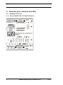
Hardware ports, switches and LEDs
Deutschmann Automation GmbH & Co. KG
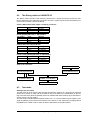
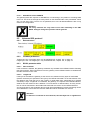
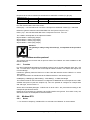
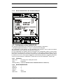
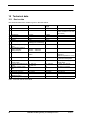
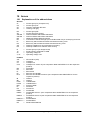
The gateway UNIGATE SC has also 8 LEDs available with the following significance:
LED Bus Power
LED Bus State
LED Power
LED State
LED Error No. / Select ID
11.4.1
green
red/green
green
red/green
yellow
CANopen® supply voltage
Interface state, CANopen
Supply voltage RS485/RS232
User-defined
User-defined
LED “Bus Power“
This LED is connected directly to the electrically isolated supply voltage of the CANopen® end.
11.4.2
LED “Bus State“
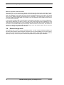
Lights green
Blinks green
Blinks red
Lights red
11.4.3
CAN-Status = OPERATIONAL
CAN-Status = PREOPERATIONAL or PREPARED
Guarding error
General CANopen® error
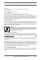
LED “Power“
This LED is connected directly to the (optionally also electrically isolated) supply voltage of the
RS485/RS232 end.
11.4.4
LED “State“
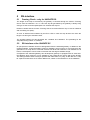
Lights green (only RS)
Flashes green (only RS)
Flashes green/red (only RS)
Lights red
Flashes red (only RS)
11.4.5
Data exchange active via RS485/RS232
RS485/RS232 ok but no permanent data exchange
No data exchange since switching on
General gateway error (see LEDs Error No.)
UNIGATE is in the configuration mode
LEDs “Error No. / Select ID“ at UNIGATE RS
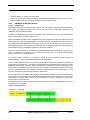
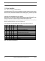
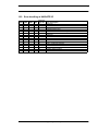
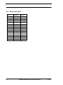
If these 4 LEDs flash and LED “State“ simultaneously lights red, the error number is displayed in
binary notation (conversion table, see Annex) in accordance with the table in Chapter "Error handling". Otherwise, the address with which communication is currently running via the RS485
interface is displayed, also in binary notation.
11.5 Switches
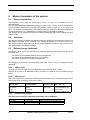
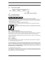
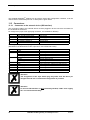
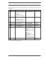
The gateway features 7 switches with the following functions:
DIP-switch
Slide switch “Termination“
Rotary coding switch S4
Rotary coding switch S5
Slide switch “Interface“
Slide switch “Termination“
11.5.1
Node-ID and Baud rate
Switchable CANopen® terminating resistor
RS485 ID (High Byte)
RS485 ID (Low Byte)
Selector switch for RS485 or RS232 interface
Switchable RS485 terminating resistor
DIP-switch
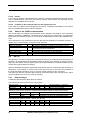
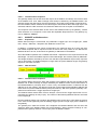
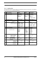
This DIP-switch is used to set the Node-ID and Baud rate.
Only the IDs 0-63 can be adjusted with the hardware DIP-switch. In order to set an address in the
area 64-127, an offset of 64 to the hardware setting is required. This setting can be carried out
with WINGATE® at CANopen® gateways from software revision 3.1 on. The setting "Node ID
Offset 64" can have the values "enabled" and "disabled". In case the value is "enabled", then the
value 64 is added to the hardware setting.
38
UNIGATE fieldbus gateway for CANopen® V. 4.2
21.4.11