1
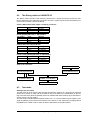
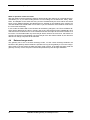
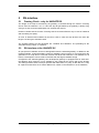
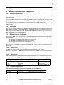
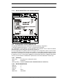
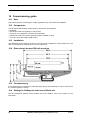
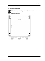
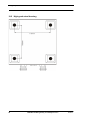
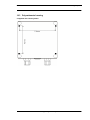
Installation guidelines Deutschmann Automation GmbH & Co. KG 14 Installation guidelines 14.1 Installation of the module The module of size (90 x 127 x 55 mm W x H x D) has been developed for switch cabinet use (IP 20) and can thus be mounted only on a standard mounting channel (deep top-hat rail to EN 50022). 14.1.1 Mounting • Engage the module from the top in the top-hat rail and swivel it down so that the module engages in position. • Other modules may be rowed up to the left and right of the module. • There must be at least 5 cm clearance for heat dissipation above and below the module. • The standard mounting channel must be connected to the equipotential bonding strip of the switch cabinet. The connection wire must feature a cross-section of at least 10 mm². • An earthing terminal must be positioned next to the module so as to allow the shield connection on the device to be implemented as short as possible with a flexible wire (1.5 mm² ). 14.1.2 Removal • First disconnect the power supply and signal lines. • Then push the module up and swivel it out of the top-hat rail. Vertical installation The standard mounting channel may also be mounted vertically so that the module is mounted turned through 90°. 14.2 Wiring 14.2.1 Connection systems The following connection systems must resp. may be used when wiring the module: • Standard screw-type/plug connection (power supply + RS) • Push-lock terminals (connection terminals for earthing) • 9-pin SUB-D plug connectors (CANopen® and RS232 connection) a) In the case of standard screw-type terminals, one lead can be clamped per connection point. It is best to then use a screwdriver with a blade width of 3.5 mm to firmly tighten the screw. Permitted cross-sections of the line: • Flexible line with wire-end ferrule: • Solid conductor: • Tightening torque: 1 x 0.25 ... 1.5 mm² 1 x 0.25 ... 1.5 mm² 0.5 ... 0.8 Nm b) The plug-in connection terminal strip is a combination of standard screw-type terminal and plug connector. The plug connection section is coded and can thus not be plugged on the wrong way round. c) The 9-pin SUB-D plug connectors are secured with two screws with "4-40-UNC" thread. It is best to use a screwdriver with a blade width of 3.5 mm to screw the screw tight. Tightening torque: 0.2... 0.4 Nm 44 UNIGATE fieldbus gateway for CANopen® V. 4.2 21.4.11