1
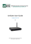
User manual
Universal Fieldbus-Gateway
UNIGATE®
UNIGATE RS232/485 - CANopen®
UNIGATE RS232/422 - CANopen®
UNIGATE SC232/485 - CANopen®
UNIGATE SC232/422 - CANopen®
V2700E
Deutschmann Automation GmbH & Co. KG Carl-Zeiss-Str. 8 D-65520 Bad Camberg
Tel:+49-(0)6434-9433-0 Hotline: +49-(0)6434-9433-33 Fax: +49-(0)6434-9433-40
Internet: http://www.deutschmann.de
Deutschmann Automation GmbH & Co. KG
1
Information on CE marking of the module . . . . . . . . . . . . . . . . 8
1.1.
1.2.
1.3.
1.4.
1.5.
2
.
.
.
.
.
.
.
.
.
.
.
.
.
.
.
.
.
.
.
.
.
.
.
.
.
.
.
.
.
.
.
.
.
.
.
.
.
.
.
.
.
.
.
.
.
.
.
.
.
.
.
.
.
.
.
.
.
.
.
.
.
.
.
.
.
.
.
.
.
.
.
.
.
.
.
.
.
.
.
.
.
.
.
.
.
.
.
.
.
.
.
.
.
.
.
.
.
.
.
.
8
8
8
8
8
Introduction . . . . . . . . . . . . . . . . . . . . . . . . . . . . . . . . . 9
EU Machinery Directive . . . . . . . . . . . . . . . . . . . . . . . . . . . 9
UNIGATE RS software flow-chart
UNIGATE SC software flow chart
UNIGATE block diagram . . . .
UNIGATE application diagram .
.
.
.
.
Configuration mode (config mode)
The Debug cable for UNIGATE SC
Test mode . . . . . . . . . . . . .
Data exchange mode . . . . . . .
.
.
.
.
.
.
.
.
.
.
.
.
.
.
.
.
.
.
.
.
.
.
.
.
.
.
.
.
.
.
.
.
.
.
.
.
.
.
.
.
.
.
.
.
.
.
.
.
.
.
.
.
.
.
.
.
.
.
.
.
.
.
.
.
.
.
.
.
.
.
.
.
.
.
.
.
.
.
.
.
11
12
13
13
.
.
.
.
.
.
.
.
.
.
.
.
.
.
.
.
.
.
.
.
.
.
.
.
.
.
.
.
.
.
.
.
.
.
.
.
.
.
.
.
.
.
.
.
.
.
.
.
.
.
.
.
.
.
.
.
.
.
.
.
.
.
.
.
.
.
.
.
.
.
.
.
.
.
.
.
.
.
.
.
14
15
15
16
Framing Check - only for UNIGATE RS . . . . . . . . . . . . . . . . . . 17
RS-interface at the UNIGATE SC . . . . . . . . . . . . . . . . . . . . . 17
General explanation . . . . . . . . . . . . . . . . . . . . . . . . . . . . 18
Interfaces . . . . . . . . . . . . . . . . . . . . . . . . . . . . . . . . . 18
Data exchange CANopen® . . . . . . . . . . . . . . . . . . . . . . . . 18
6.3.1
6.3.2
6.3.3
6.4.
6.5.
6.6.
SDO-access . . . . . . . . . . . . . . . . . . . . . . . . . . . . . . . . . . 18
PDO-access . . . . . . . . . . . . . . . . . . . . . . . . . . . . . . . . . . 18
Possible data lengths . . . . . . . . . . . . . . . . . . . . . . . . . . . . . . 18
Data exchange RS232/RS485 . . . . . . . . . . . . . . . . . . . . . . 19
The trigger byte -only at UNIGATE RS . . . . . . . . . . . . . . . . . . 19
The length byte - only at UNIGATE RS . . . . . . . . . . . . . . . . . . 19
Transparent mode - only at UNIGATE RS . . . . . . . . . . . . . . . 20
Character-Delay-Time mode - only at UNIGATE RS . . . . . . . . . . 21
8.1.
9
.
.
.
.
.
Mode of operation of the system . . . . . . . . . . . . . . . . . . . . 18
6.1.
6.2.
6.3.
7
8
.
.
.
.
.
RS-interface . . . . . . . . . . . . . . . . . . . . . . . . . . . . . . . 17
5.1.
5.2.
6
.
.
.
.
.
Operation modes of the gateway . . . . . . . . . . . . . . . . . . . . 14
4.1.
4.2.
4.3.
4.4.
5
.
.
.
.
.
Introduction . . . . . . . . . . . . . . . . . . . . . . . . . . . . . . . 10
3.1.
3.2.
3.3.
3.4.
4
.
.
.
.
.
Information for the machine manufacturer . . . . . . . . . . . . . . . 9
2.1.
2.2.
3
EU Directive EMC . . . . .
Scope of application . . . .
Note installation guidelines
Installation of the unit . . .
Working on switch cabinets
Receive direction . . . . . . . . . . . . . . . . . . . . . . . . . . . . . 21
Implemented protocols in UNIGATE RS . . . . . . . . . . . . . . . . 22
9.1.
Protocol ARCNET . . . . . . . . . . . . . . . . . . . . . . . . . . . . . 22
9.1.1
Data exchange . . . . . . . . . . . . . . . . . . . . . . . . . . . . . . . . . 22
9.1.1.1
9.1.2
Data structure . . . . . . . . . . . . . . . . . . . . . . . . . . . . . . . . . . 22
9.1.2.1
9.1.2.2
9.1.2.3
9.1.2.4
21.4.11
Broadcast . . . . . . . . . . . . . . . . . . . . . . . . . . . . . . . . . . . . . . . 22
Trigger byte .
Length byte .
ARCNET-ID
Data area . .
.
.
.
.
.
.
.
.
.
.
.
.
.
.
.
.
.
.
.
.
.
.
.
.
.
.
.
.
.
.
.
.
.
.
.
.
.
.
.
.
.
.
.
.
.
.
.
.
.
.
.
.
.
.
.
.
.
.
.
.
.
.
.
.
.
.
.
.
.
.
.
.
.
.
.
.
.
.
.
.
.
.
.
.
.
.
.
.
.
.
.
.
UNIGATE fieldbus gateway for CANopen® V. 4.2
.
.
.
.
.
.
.
.
.
.
.
.
.
.
.
.
.
.
.
.
.
.
.
.
.
.
.
.
.
.
.
.
.
.
.
.
.
.
.
.
.
.
.
.
.
.
.
.
.
.
.
.
.
.
.
.
22
22
22
22
3
Deutschmann Automation GmbH & Co. KG
9.1.3
ARCNET configuration . . . . . . . . . . . . . . . . . . . . . . . . . . . . . . 22
9.1.3.1
9.2.
ARCNET-ID of the UNIGATE . . . . . . . . . . . . . . . . . . . . . . . . . . . . . 23
Universal 232 protocol . . . . . . . . . . . . . . . . . . . . . . . . . . 23
9.2.1
9.2.2
9.2.3
Data structure . . . . . . . . . . . . . . . . . . . . . . . . . . . . . . . . . . 23
Fieldbus parameters . . . . . . . . . . . . . . . . . . . . . . . . . . . . . . . 23
RS232 parameter table . . . . . . . . . . . . . . . . . . . . . . . . . . . . . 23
9.2.3.1
9.2.3.2
9.2.3.3
9.2.3.4
9.2.3.5
9.2.3.6
9.2.4
9.3.
Start character
Length 232 . .
ID . . . . . . .
Data area . . .
Checksum . . .
End character .
.
.
.
.
.
.
9.4.
.
.
.
.
.
.
.
.
.
.
.
.
.
.
.
.
.
.
.
.
.
.
.
.
.
.
.
.
.
.
.
.
.
.
.
.
.
.
.
.
.
.
.
.
.
.
.
.
.
.
.
.
.
.
.
.
.
.
.
.
.
.
.
.
.
.
.
.
.
.
.
.
.
.
.
.
.
.
.
.
.
.
.
.
.
.
.
.
.
.
.
.
.
.
.
.
.
.
.
.
.
.
.
.
.
.
.
.
.
.
.
.
.
.
.
.
.
.
.
.
.
.
.
.
.
.
.
.
.
.
.
.
.
.
.
.
.
.
.
.
.
.
.
.
.
.
.
.
.
.
.
.
.
.
.
.
.
.
.
.
.
.
.
.
.
.
.
.
.
.
.
.
.
.
.
.
.
.
.
.
.
.
.
.
.
.
.
.
.
.
.
.
.
.
.
.
.
.
23
23
24
24
24
24
. . . . . . . . . . . . . . . . . . . . . . . . . . . 24
Data structure 3964R . . . . . . . . . . . . . . . . . . . . . . . . . . . . . . 25
Protocol definitions . . . . . . . . . . . . . . . . . . . . . . . . . . . . . . . . 25
Data communication . . . . . . . . . . . . . . . . . . . . . . . . . . . . . . . 25
9.3.3.1
9.3.3.2
9.3.3.3
9.3.3.4
9.3.3.5
9.3.4
.
.
.
.
.
.
Communication sequence . . . . . . . . . . . . . . . . . . . . . . . . . . . . 24
The 3964 R protocol
9.3.1
9.3.2
9.3.3
.
.
.
.
.
.
Initiation of data communication by the low-priority user .
Conflicts . . . . . . . . . . . . . . . . . . . . . . . . . .
Timeout times . . . . . . . . . . . . . . . . . . . . . . .
Retries . . . . . . . . . . . . . . . . . . . . . . . . . .
Initiation of data communication by the high-priority user
.
.
.
.
.
.
.
.
.
.
.
.
.
.
.
.
.
.
.
.
.
.
.
.
.
.
.
.
.
.
.
.
.
.
.
.
.
.
.
.
.
.
.
.
.
.
.
.
.
.
.
.
.
.
.
.
.
.
.
.
.
.
.
.
.
.
.
.
.
.
25
25
25
26
26
State of the 3964R communication . . . . . . . . . . . . . . . . . . . . . . . 26
RK512 . . . . . . . . . . . . . . . . . . . . . . . . . . . . . . . . . . . 26
9.4.1
9.5.
Data exchange . . . . . . . . . . . . . . . . . . . . . . . . . . . . . . . . . . 26
The fieldbus monitor protocol . . . . . . . . . . . . . . . . . . . . . . . 27
9.5.1
9.6.
Function . . . . . . . . . . . . . . . . . . . . . . . . . . . . . . . . . . . . . 27
Modbus-RTU . . . . . . . . . . . . . . . . . . . . . . . . . . . . . . . 27
9.6.1
9.6.2
Notes . . . . . . . . . . . . . . . . . . . . . . . . . . . . . . . . . . . . . . . 27
UNIGATE as Modbus-master . . . . . . . . . . . . . . . . . . . . . . . . . . 28
9.6.2.1
9.6.2.2
9.6.2.3
9.6.3
Preparation . . . . . . . . . . . . . . . . . . . . . . . . . . . . . . . . . . . . . . 28
Data structure . . . . . . . . . . . . . . . . . . . . . . . . . . . . . . . . . . . . . 28
Communication sequence . . . . . . . . . . . . . . . . . . . . . . . . . . . . . . 29
UNIGATE as Modbus-slave . . . . . . . . . . . . . . . . . . . . . . . . . . . 29
9.6.3.1
9.6.3.2
9.6.3.3
9.6.3.4
Preparation . . . . . . . .
Data structure . . . . . . .
Communication sequence
Status report . . . . . . .
.
.
.
.
.
.
.
.
.
.
.
.
.
.
.
.
.
.
.
.
.
.
.
.
.
.
.
.
.
.
.
.
.
.
.
.
.
.
.
.
.
.
.
.
.
.
.
.
.
.
.
.
.
.
.
.
.
.
.
.
.
.
.
.
.
.
.
.
.
.
.
.
.
.
.
.
.
.
.
.
.
.
.
.
.
.
.
.
.
.
.
.
.
.
.
.
.
.
.
.
.
.
.
.
.
.
.
.
.
.
.
.
.
.
.
.
.
.
.
.
29
29
29
30
10 Generating a script - only for UNIGATE SC . . . . . . . . . . . . . . . 31
10.1.
10.2.
10.3.
10.4.
10.5.
10.6.
10.7.
4
What is a script? . . . . . . . . . . . . . . .
Memory efficiency of the programs . . . . . .
What can you do with a script device? . . . .
Independence of buses . . . . . . . . . . . .
Further settings at the gateway . . . . . . . .
The use of the Protocol Developer . . . . . .
Accuracies of the baud rates at UNIGATE SC
.
.
.
.
.
.
.
.
.
.
.
.
.
.
.
.
.
.
.
.
.
.
.
.
.
.
.
.
.
.
.
.
.
.
.
.
.
.
.
.
.
.
UNIGATE fieldbus gateway for CANopen® V. 4.2
.
.
.
.
.
.
.
.
.
.
.
.
.
.
.
.
.
.
.
.
.
.
.
.
.
.
.
.
.
.
.
.
.
.
.
.
.
.
.
.
.
.
.
.
.
.
.
.
.
.
.
.
.
.
.
.
31
31
31
31
31
32
32
21.4.11
Deutschmann Automation GmbH & Co. KG
10.8. Script processing times . . . . . . . . . . . . . . . . . . . . . . . . . . 33
11 Hardware ports, switches and LEDs . . . . . . . . . . . . . . . . . . 34
11.1. Drawing of the unit . . . . . . . . . . . . . . . . . . . . . . . . . . . . 34
11.1.1 Model UNIGATE RS / SC 232/485-CANopen . . . . . . . . . . . . . . . . . 34
11.1.2 Model UNIGATE RS / SC 232/422-CANopen . . . . . . . . . . . . . . . . . 35
11.2. Configuration of the UNIGATE RS . . . . . . . . . . . . . . . . . . . . 35
11.2.1 CANopen . . . . . . . . . . . . . . . . . . . . . . . . . . . . . . . . . . . . 35
11.2.2 RS232/RS485/RS422 . . . . . . . . . . . . . . . . . . . . . . . . . . . . . . 35
11.3. Connectors . . . . . . . . . . . . . . . . . . . . . . . . . . . . . . . . 36
11.3.1
11.3.2
11.3.3
11.3.4
11.3.5
Connector to the external device (RS-interface)
CANopen® connector . . . . . . . . . . . . .
Debug plug . . . . . . . . . . . . . . . . . . .
Power supply . . . . . . . . . . . . . . . . . .
Shield terminal lead . . . . . . . . . . . . . . .
11.4. LEDs
11.4.1
11.4.2
11.4.3
11.4.4
11.4.5
.
.
.
.
.
.
.
.
.
.
.
.
.
.
.
.
.
.
.
.
.
.
.
.
.
.
.
.
.
.
.
.
.
.
.
.
.
.
.
.
.
.
.
.
.
.
.
.
.
.
.
.
.
.
.
.
.
.
.
.
.
.
.
.
.
.
.
.
.
.
.
.
.
.
.
.
.
.
.
.
36
37
37
37
37
. . . . . . . . . . . . . . . . . . . . . . . . . . . . . . . . . . . 37
LED “Bus Power“ . . . . . . . . . . . . . . .
LED “Bus State“ . . . . . . . . . . . . . . . .
LED “Power“ . . . . . . . . . . . . . . . . .
LED “State“ . . . . . . . . . . . . . . . . . .
LEDs “Error No. / Select ID“ at UNIGATE RS
.
.
.
.
.
.
.
.
.
.
.
.
.
.
.
.
.
.
.
.
.
.
.
.
.
.
.
.
.
.
.
.
.
.
.
.
.
.
.
.
.
.
.
.
.
.
.
.
.
.
.
.
.
.
.
.
.
.
.
.
.
.
.
.
.
.
.
.
.
.
.
.
.
.
.
.
.
.
.
.
.
.
.
.
.
38
38
38
38
38
11.5. Switches . . . . . . . . . . . . . . . . . . . . . . . . . . . . . . . . . . 38
11.5.1
11.5.2
11.5.3
11.5.4
11.5.5
DIP-switch . . . . . . . . . . . . . . . . .
Slide switch Termination CANopen . . . . .
Rotary coding switches S4 + S5 (RS485 ID)
Slide switch (RS485/RS232 interface) . . .
Slide switch (RS485/RS422 termination) . .
.
.
.
.
.
.
.
.
.
.
.
.
.
.
.
.
.
.
.
.
.
.
.
.
.
.
.
.
.
.
.
.
.
.
.
.
.
.
.
.
.
.
.
.
.
.
.
.
.
.
.
.
.
.
.
.
.
.
.
.
.
.
.
.
.
.
.
.
.
.
.
.
.
.
.
.
.
.
.
.
.
.
.
.
.
.
.
.
.
.
38
39
39
39
39
12 Error handling . . . . . . . . . . . . . . . . . . . . . . . . . . . . . . 40
12.1. Error handling at UNIGATE RS . . . . . . . . . . . . . . . . . . . . . . 40
12.2. Error handling at UNIGATE SC . . . . . . . . . . . . . . . . . . . . . . 41
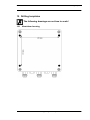
13 Housing variations . . . . . . . . . . . . . . . . . . . . . . . . . . . 42
13.1. Main operational fields for housings . . . . . . . . . . . . . . . . . . . 42
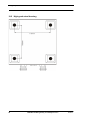
13.2. Mounting instruction . . . . . . . . . . . . . . . . . . . . . . . . . . . . 42
14 Installation guidelines . . . . . . . . . . . . . . . . . . . . . . . . . . 44
14.1. Installation of the module . . . . . . . . . . . . . . . . . . . . . . . . . 44
14.1.1 Mounting . . . . . . . . . . . . . . . . . . . . . . . . . . . . . . . . . . . . 44
14.1.2 Removal . . . . . . . . . . . . . . . . . . . . . . . . . . . . . . . . . . . . 44
14.2. Wiring . . . . . . . . . . . . . . . . . . . . . . . . . . . . . . . . . . . 44
14.2.1 Connection systems . . . . . . . . . . . . . . . . . . . . . . . . . . . . . . 44
14.2.2 CANopen® communication interface . . . . . . . . . . . . . . . . . . . . . . 45
14.2.2.1
14.2.2.2
14.2.2.3
14.2.2.4
Bus line with copper cable . . . .
Power supply . . . . . . . . . . .
Shield connection . . . . . . . .
Equipotential bonding connection
.
.
.
.
.
.
.
.
.
.
.
.
.
.
.
.
.
.
.
.
.
.
.
.
.
.
.
.
.
.
.
.
.
.
.
.
.
.
.
.
.
.
.
.
.
.
.
.
.
.
.
.
.
.
.
.
.
.
.
.
.
.
.
.
.
.
.
.
.
.
.
.
.
.
.
.
.
.
.
.
.
.
.
.
.
.
.
.
.
.
.
.
.
.
.
.
.
.
.
.
.
.
.
.
45
45
45
45
14.2.3 Line routing, shield and measures to combat interference voltage . . . . . . . 45
21.4.11
UNIGATE fieldbus gateway for CANopen® V. 4.2
5
Deutschmann Automation GmbH & Co. KG
14.2.4 General information on line routing . . . . . . . . . . . . . . . . . . . . . . . 45
14.2.4.1 Shielding of lines . . . . . . . . . . . . . . . . . . . . . . . . . . . . . . . . . . . 46
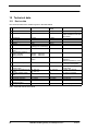
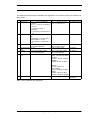
15 Technical data . . . . . . . . . . . . . . . . . . . . . . . . . . . . . . 48
15.1. Device data . . . . . . . . . . . . . . . . . . . . . . . . . . . . . . . . 48
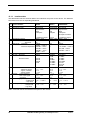
15.1.1 Interface data
. . . . . . . . . . . . . . . . . . . . . . . . . . . . . . . . . . 50
15.2. Housing data . . . . . . . . . . . . . . . . . . . . . . . . . . . . . . . 51
16 Commissioning guide . . . . . . . . . . . . . . . . . . . . . . . . . . 52
16.1. Note . . . . . . . . . . . . . . . . . . . . . .
16.2. Components . . . . . . . . . . . . . . . . .
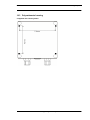
16.3. Installation . . . . . . . . . . . . . . . . . . .
16.4. Dimensional drawing DIN-rail mounting . . .
16.5. Commissioning . . . . . . . . . . . . . . . .
16.6. Setting the CANopen® address and Baud rate
16.7. CANopen® connection . . . . . . . . . . . .
16.8. Connection to the process device . . . . . . .
16.9. Connecting the supply voltage . . . . . . . .
16.10.Shield connection . . . . . . . . . . . . . . .
.
.
.
.
.
.
.
.
.
.
.
.
.
.
.
.
.
.
.
.
.
.
.
.
.
.
.
.
.
.
.
.
.
.
.
.
.
.
.
.
.
.
.
.
.
.
.
.
.
.
.
.
.
.
.
.
.
.
.
.
.
.
.
.
.
.
.
.
.
.
.
.
.
.
.
.
.
.
.
.
.
.
.
.
.
.
.
.
.
.
.
.
.
.
.
.
.
.
.
.
.
.
.
.
.
.
.
.
.
.
.
.
.
.
.
.
.
.
.
.
.
.
.
.
.
.
.
.
.
.
.
.
.
.
.
.
.
.
.
.
52
52
52
52
52
52
53
53
53
53
17 Servicing . . . . . . . . . . . . . . . . . . . . . . . . . . . . . . . . . 54
17.1. Returning a device . . . . . . . . . . . . . . . . . . . . . . . . . . . . 54
17.2. Downloading PC software and GSD files etc. . . . . . . . . . . . . . . 54
18 Annex . . . . . . . . . . . . . . . . . . . . . . . . . . . . . . . . . . . 55
18.1. Explanations of the abbreviations . . . . . . . . . . . . . . . . . . . . . 55
18.2. Hexadecimal table . . . . . . . . . . . . . . . . . . . . . . . . . . . . 56
19 Drilling templates . . . . . . . . . . . . . . . . . . . . . . . . . . . . . 57
19.1. Aluminium housing . . . . . . . . . . . . . . . . . . . . . . . . . . . . 57
19.2. High-grade steel housing . . . . . . . . . . . . . . . . . . . . . . . . . 58
19.3. Polycarbonate housing . . . . . . . . . . . . . . . . . . . . . . . . . . 59
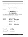
20 Declaration of conformity and certificates . . . . . . . . . . . . . . . 60
20.1. EG Certificate of Conformance . . . . . . . . . . . . . . . . . . . . . . 60
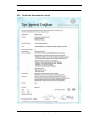
20.2. Certificate Germanischer Lloyd . . . . . . . . . . . . . . . . . . . . . . 61
6
UNIGATE fieldbus gateway for CANopen® V. 4.2
21.4.11
Deutschmann Automation GmbH & Co. KG
Disclaimer of liability
We have checked the contents of the document for conformity with the hardware and software
described. Nevertheless, we are unable to preclude the possibility of deviations so that we are
unable to assume warranty for full compliance. The information given in the publication is,
however, reviewed regularly. Necessary amendments are incorporated in the following editions.
We would be pleased to receive any improvement proposals which you may have.
Copyright
Copyright (C) Deutschmann Automation GmbH & Co. KG 1997 – 2011. All rights reserved.
This document may not be passed on nor duplicated, nor may its contents be used or disclosed
unless expressly permitted. Violations of this clause will necessarily lead to compensation in
damages. All rights reserved, in particular rights of granting of patents or registration of
utility-model patents.
Art.-No.: V2700E
21.4.11
UNIGATE fieldbus gateway for CANopen® V. 4.2
7
Information on CE marking of the module
1
Deutschmann Automation GmbH & Co. KG
Information on CE marking of the module
1.1
EU Directive EMC
The following applies to the module described in this User Manual:
Products which bear the CE mark comply with the requirements of EU Directive „Electromagnetic
Compatibility“ and the harmonized European Standards (EN) listed therein.
The EU Declarations of Conformity are available at the following location for perusal by the
responsible authorities in accordance with the EU Directive, Article 10:
Deutschmann Automation GmbH & Co. KG, Carl-Zeiss-Straße 8, 65520 Bad Camberg, Germany
1.2
Scope of application
The modules are designed for use in the industrial sector and comply with the following
requirements
Scope of application
Industry
1.3
Requirement applicable to
Emitted interference
Interference immunity
EN 55011 Kl. A
EN 61000-6-2
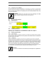
Note installation guidelines
The module complies with the requirements if you
1. comply with the installation guidelines described in the User Manual when installing and operating the module.
2. also follow the rules below on installation of the equipment and on working on switch cabinets.
1.4
Installation of the unit
Modules must be installed in electrical equipment rooms/areas or in enclosed housings (e.g.
switch boxes made of metal or plastic). Moreover, you must earth the unit and the switch box
(metal box) or at least the top-hat rail (plastic box) onto which the module has been snapped.
1.5
Working on switch cabinets
In order to protect the modules against static electrical discharge, the personnel must discharge
themselves electrostatically before opening switch cabinets or switch boxes.
8
UNIGATE fieldbus gateway for CANopen® V. 4.2
21.4.11
Deutschmann Automation GmbH & Co. KG
2
Information for the machine manufacturer
Information for the machine manufacturer
2.1
Introduction
The UNIGATE CANopen® module does not constitute a machine as defined by the EU
"Machinery“ Directive. Consequently, the module does not have a Declaration of Conformity in
relation to the EU Machinery Directive.
2.2
EU Machinery Directive
The EU Machinery Directive stipulates the requirements applicable to a machine. The term
"machine" is taken to mean a totality of connected parts or fixtures (see also EN 292-1, Paragraph 3.1)
The module is a part of the electrical equipment of the machine and must thus be included by the
machine manufacturer in the Declaration of Conformity process.
21.4.11
UNIGATE fieldbus gateway for CANopen® V. 4.2
9
Introduction
3
Deutschmann Automation GmbH & Co. KG
Introduction
The UNIGATE RS232/RS485-CANopen® or the SC232/SC485-CANopen® module serves to
adapt a serial port to the CANopen® according to CiA® DS 301. In this application, it functions
as a gateway and operates as the CANopen® slave. It can be operated by any standard-compliant master.
At the UNIGATE RS232/485 various transmission protocols are supported at the serial port:
- Modbus-RTU
- The 3964R protocol popular in Siemens equipment
- Monitoring on the basis of character delay time
- Start / End character
- Constant data lengths (Transparent mode)
- Customized protocols
These protocol variants will probably support most applications.
The module RS or SC essentially consists of the following hardware components:
• Electrically isolated interface to the CANopen
• CAN-controller SJA 1000
• Microprocessor T 89C51RD2
• RAM and EPROM
• Optionally electrically isolated RS-interface
• Serial port (RS232 and RS485) to the device connected externally
Please note: This instruction manual is valid for UNIGATE RS (standard
gateway with implemented protocols) and also for UNIGATE SC (gateway
capable for scripts).
The information given in this instruction manual is about the UNIGATE
RS and the UNIGATE SC as well, unless differences are explicitly pointed
out.
10
UNIGATE fieldbus gateway for CANopen® V. 4.2
21.4.11
Deutschmann Automation GmbH & Co. KG
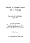
3.1
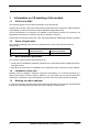
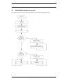
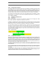
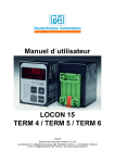
Introduction
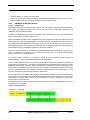
UNIGATE RS software flow-chart
The following graph shows a typical application flow of a UNIGATE fieldbus-module.
21.4.11
UNIGATE fieldbus gateway for CANopen® V. 4.2
11
Introduction
3.2
12
Deutschmann Automation GmbH & Co. KG
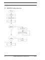
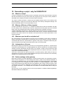
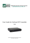
UNIGATE SC software flow chart
UNIGATE fieldbus gateway for CANopen® V. 4.2
21.4.11
Deutschmann Automation GmbH & Co. KG
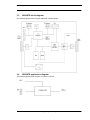
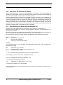
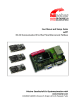
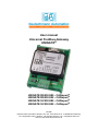
3.3
Introduction
UNIGATE block diagram
The following graph shows a typical UNIGATE module-design.
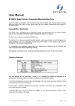
3.4
UNIGATE application diagram
The following graph shows a typical connection scheme.
21.4.11
UNIGATE fieldbus gateway for CANopen® V. 4.2
13
Operation modes of the gateway
4
4.1
Deutschmann Automation GmbH & Co. KG
Operation modes of the gateway
Configuration mode (config mode)
The configuration mode serves to configure the gateway. Adjustments at the gateway’s configuration are only possible in this mode. The gateway will be starting in this mode in case both
switches S4 as well as S5 are set on position "F" when switching on the gateway and also
RS232 is to be selected as interface. Right after switching on the gateway in the configuration
mode it will be sending its starting message, that looks analog with the following message:
"RS-CO c(dA) switch=0x0000 Prot=0x00 SN=20790120".
In the configuration mode the gateway always operates with the settings 9600 Bauds, no Parity,
8 Databits and 1 Stopbit, the RS-State LED will always be flashing red/green, the "Error
No/Select ID" LEDs are of no account for the user. All software revisions contain the configuration mode.
Connection cable from the gateway to the PC
The cable is supposed to look as follows:
Connection table 5pin screw-plug connector - PC
Screw-plug-connector
Pin 3
Pin 4
Pin 5
14
Name
Rx
Tx
GND
D-Sub plug-connector
Pin 3
Pin 2
Pin 5
UNIGATE fieldbus gateway for CANopen® V. 4.2
Name
Tx
Rx
GND
21.4.11
Deutschmann Automation GmbH & Co. KG
4.2
Operation modes of the gateway
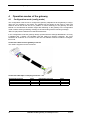
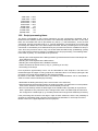
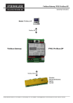
The Debug cable for UNIGATE SC
The Debug cable consists of the following components: a 9-pole D-sub-socket with two exits,
where respectively two cables are connected, one with a 3-pole Phoenix socket with mating connector and one with a 9-pole D-SUB plug.
Cable 1 (RS-product-side) 3-pole screw-plug connector
Pin number
1
2
3
Color
white
green
brown
Meaning
Rx-data
Tx-data
Gnd
D-sub (gateway RS-side), 1. RS-interface
Pin number
2
3
5
Color
white
green
brown
Meaning
Rx-data
Tx-data
Gnd
Cable 2 (PC-Com-x) 9-pole D-sub
Pin number
2
3
5
Color
white
green
brown
Meaning
Tx-diagnosis
Rx-diagnosis
Gnd
9-pole D-sub (gateway RS-side), 2. RS-interface
Pin number
4
9
5
Color
white
green
brown
Meaning
Tx-diagnosis
Rx-diagnosis
Gnd
View of the connector
PC
3-pole
screw-plug.connector
customer’s device
9-pol. D-SUB (PC-Com-x)
gateway (9 pole)
(includes 1. + 2. interface)
UNIGATE-SC
4.3
Test mode
Setting of the test mode
The test mode is set by bringing the switches S4 and S5 in position "E". Beyond it the interface
switch has to be set on "232". All other switches will not be taken into consideration for the setting of the test mode. Now the gateway has to be restarted with these settings (by a short disconnection from the power supply).
The test mode is contained from software revision V2.1 on. The test mode may be helpful to integrate the gateway in the relevant environment, for instance to "see" permanent changing data of
the fieldbus in the SPS or also in order to test the parameters of the RS-interface.
21.4.11
UNIGATE fieldbus gateway for CANopen® V. 4.2
15
Operation modes of the gateway
Deutschmann Automation GmbH & Co. KG
Mode of operation of the test mode
After the restart in the test mode the gateway will be sending the values 0-15 in hexadecimal representation ("0".."F") in ASCII-coding with the current settings for the Baud rate, Parity, Start-,
Data-, and Stopbits on the serial side every second. Simultaneously the same values are issued
binary on the fieldbus-interface provided that this is possible on the fieldbus at the moment (In
case the fieldbus has a data width of more than 1 byte, all characters of the fieldbus will be set to
the current test character).
In this mode the State-LED on the RS-side will be flashing red/green, the "Error No/Select ID"
LEDs will be displaying the value in a binary way, that is issued that moment. Additionally each
character that is received at one of the interfaces will also be output at the same interface as a
local echo. On the fielbus-side only the first byte will be used for the local echo, that means on
receiving as well as on transmitting only the first byte of the bus data is looked at, the other bus
data do not change compared to the last data.
4.4
Data exchange mode
The gateway has to be in the data exchange mode, so that a data exchange between the
RS-side of the gateway and the fieldbus is possible. As long as the gateway is not in the configuration mode or the test mode, the data exchange mode is active. In the data exchange mode the
gateway will carry out the set protocol with those parameters preset through WINGATE.
16
UNIGATE fieldbus gateway for CANopen® V. 4.2
21.4.11
Deutschmann Automation GmbH & Co. KG
5
RS-interface
RS-interface
5.1
Framing Check - only for UNIGATE RS
The length of the stop bit received by the gateway is checked through the function "Framing
Check" from the software V 2.1 on. Here the stop bit generated by the gateway is always long
enough, so that connected participants can evaluate the stop bit.
Please be aware that the function "Framing Check" becomes effective only in case of 8 data bit
and the setting "No parity".
An error is detected and indicated by the Error LEDs in case the stop bit does not show the
length 1 bit during the activated check.
The possible settings for this parameter are "enabled" and "disabled". The presetting for the
"Stop Bit Framing Check" is "enabled".
5.2
RS-interface at the UNIGATE SC
On principle the hardware cannot be distinguished from the standard gateway. In addition to the
regular hardware, a special hardware version is available, which however, is only required for the
generation of a script. Due to technical reasons this advanced hardware is not available for all
buses; a development can be made on another than the target hardware though.
Compared to the standard gateway, this development gateway is equipped with an extra-interface RS232, which however, is only available to the outside at the version with 9-pole D-SUB.
This debug-interface itself is always operated with 9600 baud, no parity, 8 data bits and 1 stop
bit. Apart from that there are no further differences, neither in the software nor in the hardware.
21.4.11
UNIGATE fieldbus gateway for CANopen® V. 4.2
17
Mode of operation of the system
6
Deutschmann Automation GmbH & Co. KG
Mode of operation of the system
6.1
General explanation
Communication can be split into seven layers, Layer 1 to Layer 7, in accordance with the
ISO/OSI Model.
The DEUTSCHMANN AUTOMATION gateways convert Layers 1 and 2 of the customized bus
system (RS485 / RS232) to the corresponding fieldbus system. Layers 3 to 6 are blank, and
Layer 7 is forwarded transparently on the standard gateways. However, customized adaptations
are also possible here (e.g. adaptations to existing profiles of the fieldbus systems).
The gateway can be configured through the software WINGATE® that is also supplied (see also
chapter 11.2).
6.2
Interfaces
The gateway features the RS232 and RS485 interfaces. Switchover is performed by means of a
slide switch accessible for the customer. The CANopen® gateway thus allows access to all
devices connected to the RS485 bus via one single CANopen® Node-ID resp. access to the
device connected to the RS232 interface.
6.3
Data exchange CANopen®
The following three objects are existing in the CANopen-gateway for the data exchange on the
CANopen-side:
- Adr. 2000H (Type DOMAIN):Data received by the gateway
- Adr. 2001H (Type DOMAIN):Data sent by the gateway
- Adr. 2002H (Type BYTE):Length of the data sent
The length of the receiving- and transmitting buffer (Obj. 2000 + 2001) is configured through
WINGATE®.
6.3.1
SDO-access
Generally the data can always be exchanged through SDO’s (Obj. 2000 - 2002).
Likewise an access to all Mandatory-objects according to CiA® DS 301 is possible through
SDO’s.
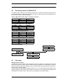
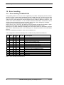
6.3.2
PDO-access
PDO’s are supported according to the following table depending on the configured length and the
PDO-length is set dynamically to the correct value:
Gateway
receiving-data
Max. 8 Byte
Max. 8 Byte
>8 Byte
>8 Byte
6.3.3
Gateway
transmitting-data
Max. 8 Byte
>8 Byte
Max. 8 Byte
>8 Byte
Receiv.-PDO1
(Adr = 512 + ID)
Receiv. data
Receiv. data
-
Transm.-PDO1
(Adr = 384 + ID)
Transm. data
Length transmitting data
Transm. data
Length transmitting data
Possible data lengths
The table below shows the maximum transferable data in CANopen:
Input data
Output data
Emergency data
18
max. 255 bytes
max. 255 bytes
1 byte
Variable: maximum value in this case
Variable: maximum value in this case
See chapter Error handling
UNIGATE fieldbus gateway for CANopen® V. 4.2
21.4.11
Deutschmann Automation GmbH & Co. KG
6.4
Mode of operation of the system
Data exchange RS232/RS485
Data exchange via the RS interface can be programmed as follows:
• Cyclic
• Only if input data changes
• Only if trigger byte changes
All data is transferred consistently by the gateway in both directions.
Structure of the data:
Trigger byte
Length byte
User data
See "The trigger byte -only at UNIGATE RS", chapter 6.5‚ on page 19
See "The length byte - only at UNIGATE RS", chapter 6.6‚ on page 19
Trigger byte and length byte are contained only if configured accordingly.
6.5
The trigger byte -only at UNIGATE RS
In case data is transferred cyclically via CANopen® (normally that is not the case), the gateway
must detect when the user wishes to send new data via the serial port. For this reason, the user
can set control of transmission via a trigger byte. In this mode, the gateway always sends (and
only sends) when the trigger byte is changed.
If Trigger-Byte mode is activated, the gateway increments the trigger byte each time a telegram
has been received.
The first byte in the CANopen® input/output data buffer is used as the trigger byte if this mode is
activated.
6.6
The length byte - only at UNIGATE RS
The user can configure whether the transmit length is also to be stored as a byte in the input/output data area. In transmit direction, as many bytes as specified in this byte are sent. On reception
of a telegram, the gateway enters the number of characters received.
21.4.11
UNIGATE fieldbus gateway for CANopen® V. 4.2
19
Transparent mode - only at UNIGATE RS
7
Deutschmann Automation GmbH & Co. KG
Transparent mode - only at UNIGATE RS
The data is transferred transparently with no timeout monitoring functions whatsoever. The user
presets the data on the master. This data is then forwarded to the external device with no timeout
monitoring functions whatsoever. A response from the external device is also forwarded to the
master with no changes. Any security mechanisms must be encrypted by the user in the net
data.
20
UNIGATE fieldbus gateway for CANopen® V. 4.2
21.4.11
Deutschmann Automation GmbH & Co. KG
8
Character-Delay-Time mode - only at UNIGATE RS
Character-Delay-Time mode - only at UNIGATE RS
The ’Character-delay-time mode’ is not a protocol but a special variant of the “Universal 232“ protocol’ (see corresponding chapter).
8.1
Receive direction
Data received is entered in the transmit buffer until the character delay time expires after reception of the last character. This time can be configured.
Transmit direction: The data is transmitted transparently.
21.4.11
UNIGATE fieldbus gateway for CANopen® V. 4.2
21
Implemented protocols in UNIGATE RS
9
Deutschmann Automation GmbH & Co. KG
Implemented protocols in UNIGATE RS
9.1
Protocol ARCNET
ARCNET stands for Attached Resource Computer NETwork.
It belongs to the group of Token-Bus-Networks. ARCNET is based on a multi master concept,
that means every ARCNET participant is in the position to communicate with every other ARCNET participant without restrictions.
9.1.1
Data exchange
This protocol allows a connection between ARCNET and CANopen.
With it those data, sent to the UNIGATE via CANopen, are passed on via ARCNET in accordance with the data structure described below. Here only those data packets are included that
have been sent to the ARCNET-ID of the UNIGATE.
Data, the gateway receives via ARCNET, are passed on correspondingly via CANopen. With it
the parameters configurable with WINGATE (Trigger- and lengthbyte) are included.
The length of the receive buffers and transmission buffers is also configured via WINGATE.
The mapping of the data to SDO’s and PDO’s is described in chapter 6.3 (Data exchange CANopen®).
9.1.1.1
Broadcast
In case the destination address equals „0“, the data are sent to each ARCNET participant.
9.1.2
Data structure
ARCNET
-
-
-
Data area
CANopen
Triggerbyte (opt.)
Lengthbyte (opt.)
ARCNET-ID
Data area
9.1.2.1
Trigger byte
See „The trigger byte -only at UNIGATE RS“, chapter 6.5.
9.1.2.2
Length byte
See „The length byte - only at UNIGATE RS“, chapter 6.6.
9.1.2.3
ARCNET-ID
In case the data are transmitted from UNIGATE via CANopen, this byte is the ID of the ARCNET
sender.
In the opposite direction (data get to the UNIGATE via CANopen), here the CANopen-sender
registers the ARCNET-ID to which the gateway is supposed to send the data.
9.1.2.4
Data area
In this field the useful data are copied transparently from ARCNET to CANopen® and the other
way round.
9.1.3
ARCNET configuration
• Baud rate: 2.5 MBaud
• Short packet (is determined by the entry fieldbus length)
22
UNIGATE fieldbus gateway for CANopen® V. 4.2
21.4.11
Deutschmann Automation GmbH & Co. KG
9.1.3.1
Implemented protocols in UNIGATE RS
ARCNET-ID of the UNIGATE
The gateway itself also requires an ARCNET-ID, in order being in the position to exchange data
in the net. This ID is set through the rotary switch on the ARCNET side. Here permissible values
are 1 to 254 (01H..FEH). The ID 0 is not permitted, as it is the broadcast-address. 255 is only
used for the configuration.
Attention:
The rotary switches are only read in once when switching on the UNIGATE. Changes during the operation will be ignored!
9.2
Universal 232 protocol
9.2.1
Data structure
9.2.2
Fieldbus parameters
Trigger byte: See "The trigger byte -only at UNIGATE RS", chapter 6.5‚ on page 19
Length byte: See "The length byte - only at UNIGATE RS", chapter 6.6‚ on page 19
9.2.3
RS232 parameter table
9.2.3.1
Start character
If this character is defined, the gateway evaluates only the data at the RS232 interface following
this start character. Each transmission from the gateway via the RS232 interface is initiated with
the start character in this case.
9.2.3.2
Length 232
If this byte is activated, the gateway, at the receive end, awaits as many bytes of useful data
(without checksum) as specified in this byte by the RS232 transmitter. At the transmission end,
the gateway then sets this byte to the number of useful data items transmitted by it (without
checksum). If byte "Length232" is not defined, the gateway, on reception at the RS232 interface,
waits for the end criterion if this is defined. If no end criterion is defined either, as many characters as can be transferred in the fieldbus transmit buffer are read in via the RS232 interface.
As a special case for this parameter also a length byte with additional Timeout monitoring can be
set in WINGATE. In that case the received characters will be discarded at a Timeout.
Attention:
If "Timeout“ is selected as end character, then this byte has no significance.
21.4.11
UNIGATE fieldbus gateway for CANopen® V. 4.2
23
Implemented protocols in UNIGATE RS
9.2.3.3
Deutschmann Automation GmbH & Co. KG
ID
This byte is present only for reasons of compatibility. It is never activated.
9.2.3.4
Data area
The useful data is transferred in this field.
9.2.3.5
Checksum
At the universal 232 protocol the following checksums can be selected:
XOR, bytewise sum, XOR with negated result and bytewise sum with negated result.
The checksum is always generated on the basis of bytes "Length232“, "ID“ and "Data area“ if
present. The checksum is generated by the gateway at the transmit end independently. On
reception from the RS232 interface, the gateway checks the checksum and then transfers the
useful data (without checksum) to the fieldbus buffer if no checksum errors have been detected.
Otherwise, a local error message issued.
9.2.3.6
End character
If this character is defined, the gateway receives data from the RS232 interface up to this character. The "Timeout" criterion can be defined as a special case. In this case, the gateway continues
to receive characters until a defined pause occurs. In the special case "Timeout" the "Length
232-byte" has no significance. At the transmit end, the gateway inserts the end character, if
defined, as the last character of a transmission.
Attention:
The configuration of an end character together with a check sum should
be avoided, as a check sum that exactly corresponds with the end character might be the result. In such a case a misinterpretation and following a checksum-error is the result.
9.2.4
Communication sequence
The useful data (data area) arriving via the fieldbus is copied in accordance with chapter 9.2.1
transparently into the RS232 data field and transferred via the RS interface, whereby the protocol
is supplemented in accordance with the configuration (start character, end character...). NO
acknowledgement is issued !
If the "Trigger byte“ (see chapter 6.5) is active, data is sent only on a change of this byte. If the
"Length byte" (see chapter 6.6) is active, only as many of the following bytes as specified there
are transferred.
Receive data at the RS interface is evaluated in accordance with the configured protocol, and the
data field (data area (see chapter 9.2.1)) is sent to the fieldbus-master. If more characters have
been received than the fieldbus block length, the trailing bytes are truncated and an Rx Overrun
is indicated. If less have been received, padding with 0 occurs. If the "Length byte" is active, the
number of received useful data items is entered there. If the, "Trigger byte" is active, this is incremented by one after each complete reception operation at the RS interface.
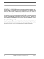
9.3
The 3964 R protocol
The 3964 protocol is used to transfer data between two serial devices. One partner must be a
high-priority partner and the other must be a low-priority partner in order to resolve initialisation
conflicts.
24
UNIGATE fieldbus gateway for CANopen® V. 4.2
21.4.11
Deutschmann Automation GmbH & Co. KG
9.3.1
Data structure 3964R
9.3.2
Protocol definitions
Implemented protocols in UNIGATE RS
The telegram format is as follows:
STX
Data
DLE
ETX
BCC
• The received net data is forwarded (transparently) in both directions unchanged.
Attention: The DLE-doubling is excluded from it; that means one DLE (10H) on the bus-side is
sent on the RS-side twice. A double DLE on the RS-side is only sent once to the bus-master.
• Data blocking is not scheduled.
• The net data length is restricted to 236 bytes per telegram.
• Communication always runs between high-priority and low-priority communication partners.
Attention:
The gateway is always using "Even Parity", as stipulated in the specification.
9.3.3
Data communication
9.3.3.1
Initiation of data communication by the low-priority user
If the low-priority user also receives an STX in response to a transmitted STX, it interrupts its
transmit request, reverts to Receive mode and acknowledges the received STX with DLE.
A DLE in the data string is duplicated and included in the checksum. The BCC is computed from
XORing all characters.
9.3.3.2
Conflicts
9.3.3.3
Timeout times
The timeout times are preset by the definition of the 3964R protocol and cannot be overwritten !!!
tq = acknowledgement timeout time (2 s).
The acknowledgement timeout time is started after transmission of control character STX. If no
positive acknowledgement arrives within the acknowledgement timeout time, the job is repeated
(max. 2 x). If it has not been possible to complete the job positively after two repetitions, the
high-priority device nevertheless attempts to establish contact with the low-priority partner by
transmitting STX (cycle corresponds to tq).
tz = character timeout time ( 200 ms)
If the 3964 R driver receives data, it monitors arrival of the individual characters within period tz.
If no character is received within the timeout time, the protocol terminates transfer. No
acknowledgement is sent to the coupling partner.
21.4.11
UNIGATE fieldbus gateway for CANopen® V. 4.2
25
Implemented protocols in UNIGATE RS
9.3.3.4
Deutschmann Automation GmbH & Co. KG
Retries
In the event of negative acknowledgement or timeout, a telegram transmitted by the high-priority
user is repeated twice. After this, the gateway signals communication as disturbed but still
attempts to re-establish the connection.
9.3.3.5
Initiation of data communication by the high-priority user
In the case of a negative acknowledgement or timeout, a telegram transmitted by the external
device is repeated twice before a fault is signalled.
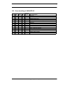
9.3.4
State of the 3964R communication
The current state of the 3964R communication will be mapped in the fieldbus, if the parameter
3964R is activated in WINGATE. The states can be taken from the below table. This parameter
takes effect from software revision 3.41 on and can be adjusted by means of the WINGATE software.
This information is only presented in the bus data from the gateway to the Master, however, it
applies to the communication via 3964R in both directions.
Name
3964R_NO_ACTION
3964R_WAIT_AFTER_STX
Value
0
1
3964R_WAIT_QUITTUNG
3964R_WAIT_DATA
3964R_WAIT_ZVZ
2
5
9
9.4
Description
If this value is presented, no 3964R communication is active.
After the transmission of the STX character the sender waits until
the receiver has sent its confirmation.
The receipt character is waited for.
The gateway waits as reveiver for the useful data.
An execution time is waited for.
RK512
The gateway is not able to support the entire RK512-protocol (any data length through sequence
telegram), as the handshake to the fieldbus-master is getting more complex, as though the gateway only uses 3964R, and the higher protocol is directly handled by the fieldbus-master (4 byte
receipt and response data if necessary).
However, UNIGATE supports a simple kind of the RK512-protocol, whereas the data exchange is
restricted to 1 word (fixed). In return the end user does not have to care about the problems of
the quasi-full-duplex-operation, since he receives a fixed response to any command.
And apart from that the complete data exchange exclusively takes place through PDO’s, which
can be handled by any PLC very easily and quickly.
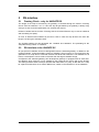
9.4.1
Data exchange
In detail the data exchange takes place as follows:
Commands from the RS1-side: PDO1 (Tx) [6 byte]
PDO1 (Tx) byte
RK512-byte
1
Cmd
3
2
Typ
4
3
DB
5
4
DW
6
5
DatH
11
6
DatL
12
(At FETCH Byte 5 + 6 equal 0)
Dat only at CmD=SEND
Response to the above mentioned command from fieldbus-master in PDO1 (Rx) [2 byte]
PDO1 (Rx) byte
1
Dat
Receipt
2
Dat
Receipt
(At FETCH)
(At SEND) = last two byte of the RK512-receipt
Commands from fieldbus-master = PDO2 (Rx) [6 byte]
PDO2 (Rx) byte
RK512-byte
26
1
Cmd
3
2
Typ
4
3
DB
5
4
DW
6
5
DatH
11
6
DatL
12
(Any byte 5 + 6 at FETCH)
(Dat only at Cmd=SEND)
UNIGATE fieldbus gateway for CANopen® V. 4.2
21.4.11
Deutschmann Automation GmbH & Co. KG
Implemented protocols in UNIGATE RS
Response to the above mentioned command from UNIGATE in PDO2 (Tx) [2 byte]
PDO2 (Tx) byte
1
Dat
Receipt
2
Dat
Receipt
(At FETCH)
(At SEND) = last two byte of the RK512-receipt
Examples:
PLC will describe DB3, DW7 with 1234H:
PDO2 (Rx) = 41H 44H 03H 07H 12H 34H=> Receipt from UNIGATE: PDO2 (Tx) = 00H 00H
RS-device gets the data word from DB2 DW9 from PLC (there it says 4711H)
PDO1 (Tx) = 45H 44H 02H 09H 00H 00H=> Response from PLC: 47H 11H
The 4 PDO’s are depicted on the objects as follows:
Object 2000H = PDO2 (Rx) (6 byte)
Object 2001H = PDO1 (Tx) (6 byte)
Object 2002H = PDO2 (Tx) (2 byte)
Object 2003H = PDO1 (Rx) (2 byte)
Attention:
The gateway is always using "Even Parity", as stipulated in the specification.
9.5
The fieldbus monitor protocol
This protocol has the function that all process data of the fieldbus are made available via the
RS232 interface.
9.5.1
Function
For other CANopen® participants the gateway seems to be a normal CANopen-slave with 1 Rx
and 1 Tx PDO each 1 byte as well as the objects 2000H to 2002H. The PDO’s and objects are
not used though.
Instead the gateway filters all PDO’s out of the CAN data transfer whose COB-ID is in sector
181H..57FH.
The data of the PDO’s is transferred via the RS232 interface in the following form:
COBID(low), COBID(high), PDO-Data(1)...PDO-Data(n) ; n=PDO data length
The transfer format on the RS interface is configured via WINGATE and corresponds to the UNIVERSAL-232 protocol (see also chapter 9.2). Thus it is possible to configure for example start
and end signs, check sums a.s.o.
All the other CAN data packages - COB-ID out of 181H..57FH - are processed according to the
CANopen® specification DS301.
Data that are received by the gateway via the RS interface are ignored. Thus there is only one
data stream from the CANopen® to the RS interface.
9.6
9.6.1
Modbus-RTU
Notes
For reasons of simplicity, "Modbus-RTU“ is referred to as "Modbus“ in the text below.
21.4.11
UNIGATE fieldbus gateway for CANopen® V. 4.2
27
Implemented protocols in UNIGATE RS
Deutschmann Automation GmbH & Co. KG
"Modbus-ASCII“ is currently not supported.
The terms "input“ and "output“ are always viewed from the gateway’s point of view, i. e. field-
bus input data is the data sent by the fieldbus-master to the gateway.
9.6.2
UNIGATE as Modbus-master
9.6.2.1
Preparation
Before data exchange is commenced, the "Baud rate" and "Parity" parameters and, if applicable,
the "Trigger byte" and the "Length byte" must be set. The number of "Start bits", "Stop bits" and
"Data bits" are permanently preset.
In addition, a "Response time" which corresponds to the maximum time up to which the Modbus
slave responds after a request must be set.
Since the Modbus operates with a variable data format - dependent on the required function and
data length - but since the fieldbus requires a fixed data length, this must be preset by means of
the configuration with WINGATE®. This length should be selected by the user such that the longest Modbus request resp. response can be processed. If a Modbus response is longer than the
preset fieldbus length, the gateway signals an "Rx buffer overflow“.
The user can choose whether the fieldbus requests are forwarded to the Modbus cyclically, in the
event of a change, or on request. If he chooses cyclic mode, the next request follows directly
after a response of the Modbus slave.
In "Change" mode, detection of a change is based on the fact that the fieldbus data are
transferred only in case of an SDO/PDO-request via the Modbus.
The third mode (Modus request on request) necessitates the first byte in the fieldbus containing a
trigger byte (see chapter 6.5). This byte is not transferred to the Modbus and serves only to start
a Modbus transmission. For this purpose, the gateway constantly monitors this trigger byte and
sends data to the Modbus only when this byte has changed. In the reverse direction (to the fieldbus), the gateway transfers the number of received Modbus data records in this byte, i.e. this
byte is incremented by the gateway after each data record.
If the "Length byte“ is activated (see chapter 6.6), the gateway transfers only the number of bytes
specified there. The number of received Modbus data items is saved in the direction of the fieldbus-master. The length always refers to bytes "Address" to "Dat n" (inclusive in each case),
always without CRC checksum.
As the gateway determines the data length independently by means of the Modbus function, the
length byte is not required.
9.6.2.2
28
Data structure
UNIGATE fieldbus gateway for CANopen® V. 4.2
21.4.11
Deutschmann Automation GmbH & Co. KG
9.6.2.3
Implemented protocols in UNIGATE RS
Communication sequence
The gateway always acts as the slave with respect to the fieldbus and always acts as the master
at the Modbus end. Thus, data exchange must always be started by the fieldbus-master. The
gateway fetches this data which must be structured in accordance with Chapter "Data structure“,
from the fieldbus-master, determines the valid length of the Modbus data if the length byte is not
activated, adds the CRC checksum and sends this data record as a request on the Modbus.
The response of the selected slave is then sent to the fieldbus-master by the gateway - without
CRC checksum. If no response occurs within the stipulated "Response time", the gateway signals a "TIMEOUT ERROR".
9.6.3
UNIGATE as Modbus-slave
9.6.3.1
Preparation
Before data exchange is commenced, the parameters "Trigger byte" and "Length byte", "Baud
rate", "Parity", "Start bits", "Stop bits" and "Data bits" must be set.
In addition, a "Response time" which corresponds to the maximum time up to which the fieldbus-master responds after a request must be set and at the rotary switch on the RS-side the
Modbus-ID has to be set, under which the gateway is addressed in the Modbus.
Since the Modbus operates with a variable data format - dependent on the required function and
data length - but since the fieldbus requires a fixed data length, this must be preset by UNIGATE.
This length should be selected by the user such that the longest Modbus request resp. response
can be processed. If a fieldbus-telegram is longer than the preset fieldbus length, the gateway
signals an "Rx buffer overflow“.
9.6.3.2
Data structure
9.6.3.3
Communication sequence
The gateway always acts as the slave with respect to the fieldbus and also acts as slave at the
Modbus end. A data exchange is always initiated by the Modbus-master via the RS-interface. If
the Modbus-address (1st Byte) which is sent out by the Modbus-master is identical with the
address set on the gateway, the gateway sends the received data (without Modbus-address and
CRC-check sum) to the fieldbus-master (look picture above). With it the gateway optionally completes as an introduction a Trigger byte and a Length byte.
The fieldbus-master detects when it has to analyze a record via the Trigger byte which is incremented by the gateway at every inquiry. The number of the following Modbus-data is to be found
in the length byte.
Now the fieldbus-master has to analyze the Modbus-inquiry and it has to send back the answer
in the same format (optionally with the leading Trigger byte and Length byte) via the fieldbus to
the gateway.
The gateway then takes this answer and completes the Modbus-address and the CRC and
sends the data to the Modbus-master via the RS-interface. With it the data exchange is completed and the gateway waits for a new inquiry from the Modbus-master.
21.4.11
UNIGATE fieldbus gateway for CANopen® V. 4.2
29
Implemented protocols in UNIGATE RS
9.6.3.4
Deutschmann Automation GmbH & Co. KG
Status report
If no response occurs within the stipulated "Response time" from the fieldbus-master, the gateway a "Timeout-Error".
The last Modbus-ID that was transferred to the RS-interface is indicated by the yellow LEDs.
30
UNIGATE fieldbus gateway for CANopen® V. 4.2
21.4.11
Deutschmann Automation GmbH & Co. KG
Generating a script - only for UNIGATE SC
10 Generating a script - only for UNIGATE SC
10.1 What is a script?
A script is a sequence of commands, that are executed in that exact order. Because of the fact
that also mechanisms are given that control the program flow in the script it is also possible to
assemble more complex processes from these simple commands.
The script is memory-oriented. It means that all variables always refer to one memory area.
While developing a script you do not have to take care of the memory management though. The
Protocol Developer takes on this responsibility for you.
10.2 Memory efficiency of the programs
A script command can carry out e. g. a complex checksum like a CRC-16 calculation via data.
For the coding of this command only 9 byte are required as memory space (for the command
itself). This is only possible when these complex commands are contained in a library.
A further advantage of this library is, that the underlying functions have been in practical use for a
couple of years and therefore can be described as ’void of errors’. As these commands are also
present in the native code for the controller, at this point also the runtime performance of the
script is favorable.
10.3 What can you do with a script device?
Our script devices are in the position to process a lot of commands. In this case a command is
always a small firmly outlined task. All commands can be put into classes or groups. A group of
commands deals with the communication in general. This group’s commands enable the gateway to send and receive data on the serial side as well as on the bus-side.
10.4 Independence of buses
Basically the scripts do not depend on the bus, they are supposed to operate on. It means that a
script which was developed on a Profibus gateway can also be operated on an Interbus without
changes, since the functioning of these buses is very similar. In order to also process this script
on an Ethernet gateway, perhaps further adjustments have to be made in the script, so that the
script can be executed reasonably.
There are no fixed rules how which scripts have to operate properly. When writing a script you
should take into account on which target hardware the script is to be executed, so the necessary
settings for the respective buses can be made.
10.5 Further settings at the gateway
Most devices require no further adjustments, except for those made in the script itself. However,
there are also exceptions to it. These settings are made by means of the software WINGATE. If
you know our UNIGATE-series, you are already familiar with the proceeding with it. An example
is the adjustment of the IP-address and the net-mask of an Ethernet-gateway. These values
have to be known as fixed values and are not available for the runtime. Another reason for the
configuration of the values in WINGATE is the following: After an update of the script these values remain untouched, i. e. the settings that were made once are still available after a change of
the script.
Only this way it is also possible that the same script operates on different Ethernet-gateways,
that feature different IP-addresses.
21.4.11
UNIGATE fieldbus gateway for CANopen® V. 4.2
31
Generating a script - only for UNIGATE SC
Deutschmann Automation GmbH & Co. KG
10.6 The use of the Protocol Developer
The Protocol Developer is a tool for an easy generation of a script for our script gateways. Its
operation is exactly aimed at this use. After starting the program the script that was loaded the
last time is loaded again, provided that it is not the first start.
Typical for Windows script commands can be added by means of the mouse or the keyboard. As
far as defined and required for the corresponding command, the dialog to the corresponding
command is displayed, and after entering the values the right text is automatically added to the
script. The insertion of new commands by the Protocol Developer is carried out in a way that
existing commands will not be overwritten. Generally a new command is inserted in front of the
one where the cursor is positioned. Of course the commands can also be written by means of the
keyboard or already written commands can also be modified.
10.7 Accuracies of the baud rates at UNIGATE SC
The baud rate of the serial interface is derived from the processor’s crystal frequency.
Meanwhile all Script-gateways, except for the MPI-Gateways (20 MHz), are working with a crystal frequency of 40 MHz.
You can enter any desired integer baud rate into the script. After that the firmware adjusts the
baud rate, that can be derived the most precisely from the crystal frequency.
The baud rate the gateway is actually working with (BaudIst) can be determined as follows:
BaudIst = (F32 / K)
F32
= Crystal frequency [Hz] / 32
K
= Round (F32 / BaudSoll);
Round () is a commercial roundoff
Example:
The actual baud rate is to be calculated, when 9600 baud are pre-set, where the gateway is
operated with 40 MHz:
F32
= 40000000 / 32 = 1250000
K
= Round(1250000 / 9600) = Round(130.208) = 130
BaudIst = 1250000 / 130 = 9615.38
I. e.: The baud rate actually adjusted by the gateway is 9615.38 baud
The resulting error in per cent can be calculated as follows:
Error[%] = (abs(BaudIst - BaudSoll) / BaudSoll) * 100
In our example the following error results:
Error
= (abs(9615.38 - 9600) / 9600) * 100 = 0.16%
In practise errors below 2% can be tolerated!
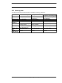
In the following please find a listing of baud rates at a 40 MHz-crystal frequency with the corresponding errors:
32
UNIGATE fieldbus gateway for CANopen® V. 4.2
21.4.11
Deutschmann Automation GmbH & Co. KG
4800 baud:
9600 baud:
19200 baud:
38400 baud:
57600 baud:
62500 baud:
115200 baud:
312500 baud:
625000 baud:
Generating a script - only for UNIGATE SC
0.16%
0.16%
0.16%
1.35%
1.35%
0%
1.35%
0%
0%
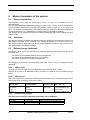
10.8 Script processing times
The Script is translated by the Protocol Developer and the consequently generated code is
loaded into the Gateway. Now the processor in the Gateway interprets this code. In this case,
there are commands that can be processed very fast (e. g. "Set Parameter"). There are also
commands, however, that take longer (e. g. copying 1000 bytes). Consequently, for one thing the
processing time differs due to the kind of Sript command. But the processing time of the Script
commands is considerably more determined by the processor time that is available for this process. Since the processor has to carry out several tasks simultaneously (multitasking system)
only a part of the processor's capacity is available for the Script processing. The following tasks in the order of priority - are executed on the processor:
• Sending and receiving data at the Debug-interface (provided that the Protocol Developer has
been started on the PC)
• Sending and receiving data at the RS-interface
• Sending and receiving data at the Fieldbus-interface
• Tasks controlled via internal clock (1 ms) (e. g. flashing of an LED)
• Processing of the Script
From experience approximately 0.5 ms can be calculated for each Script line. This value confirmed itself again and again in many projects as a standard value. He is always quite right if the
processor has enough time available for the Script processing.
By means of the tasks mentioned above, the following recommendation can be formulated in
order to receive a rather fast Script processing:
• Deactivate the Debug-interface (it is the normal case in the serial use)
• Keep the data length at the RS-interface as small as possible. The baud rate is not the problem
here, but the amount of characters which are transfered per second.
• Do not unnecessarily extend the data length at the Fieldbus side. Especially at acyclical bus
data, if possible do only send them when changes were made. The data length at buses that
are configured to a fixed length (e. g. Profibus) should not be longer than absolutely necessary.
If the processing time should be too large in spite of these measures, there is the possibility to
generate a customized Script command, that executes several tasks in one Script command.
Please contact our support department for this purpose.
21.4.11
UNIGATE fieldbus gateway for CANopen® V. 4.2
33
Hardware ports, switches and LEDs
Deutschmann Automation GmbH & Co. KG
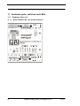
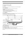
11 Hardware ports, switches and LEDs
11.1 Drawing of the unit
11.1.1
34
Model UNIGATE RS / SC 232/485-CANopen
UNIGATE fieldbus gateway for CANopen® V. 4.2
21.4.11
Deutschmann Automation GmbH & Co. KG
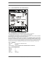
11.1.2
Hardware ports, switches and LEDs
Model UNIGATE RS / SC 232/422-CANopen
11.2 Configuration of the UNIGATE RS
The gateway is delivered by the manufacturer with the following configuration
- Transparent data transmission (i.e. Layer 7 is transferred unchanged)
The configuration of the gateway can be changed by the customer. That is what the software
WINGATE® that comes along with the gateway is meant for.
For the configuration the gateway has to be brought to the configuration mode. For that reason
the switches S4 and S5 have to be set to the position "F" each and the interface-switch has to be
set to "232". Consequently a connection to the PC has to be established and the gateway has to
be started once more. The program WINGATE® automatically selects the interface parameters
correctly. For the operation of WINGATE® please take a look at the WINGATE® Online help.
11.2.1
CANopen
According to the setting DIP-switch
• Baud rate:
• Sync:
Supported
• Node guarding: Supported (Default value: Guardtime=500 ms Lifetime=3)
11.2.2
RS232/RS485/RS422
• Start bit:
• Data bits:
• Stop bit:
• Parity:
• Baud rate:
21.4.11
1
8
1
None
9600 Baud
UNIGATE fieldbus gateway for CANopen® V. 4.2
35
Hardware ports, switches and LEDs
Deutschmann Automation GmbH & Co. KG
The supplied WINGATE® software can be used to change this configuration. Likewise, it can be
used to select customized protocols. A description is given below.
11.3 Connectors
11.3.1
Connector to the external device (RS-interface)
The connection cable to the external device must be plugged in at the connector accessible on
the underside of the device.
Pin assignment (5-pin screw-type plug connector; not available for RS422)
Pin No.
1
2
3
4
5
Name
10.8..30 V/DC power supply
0 V power supply
RX / RS485- (RS485 B)
TX / RS485+ (RS485 A)
GND
Function
Power supply
Power supply
Receive signal
Transmit signal
Reference for PIN 3 + 4
Pin assignment (9-pin Sub-D, plug)
(Standard for the RS232/422-model, optional for the RS232/485-model)
Pin No.
1
2
3
4
5
6
7
8
9
Name
Shield
Rx
RS485RS422- (Tx)
Tx
RS485+
RS422+ (Tx)
Function
Receive signal
Transmit-receive signal
Transmit signal
Transmit signal
Transmit-receive signal
Receive signal
GND
RS422- (Rx)
RS422+ (Rx)
Ground connection, reference for PIN 2+3+6+7
Receive signal
Receive signal
Attention:
The assignment of the 9-pin Sub-D plug may differ from the above pin
assignment and also a customized configuration is possible.
Attention:
In case the RS-interface is NOT potentially divided, "GND" and "supply
0V" are connected internally!
36
UNIGATE fieldbus gateway for CANopen® V. 4.2
21.4.11
Deutschmann Automation GmbH & Co. KG
Hardware ports, switches and LEDs
Attention:
In case RS422 is selected, then the termination switch has to be set to
ON, in order to avoid communication errors!
Pin assignment (2-pin screw-type/plug connector; only in conjunction with 9-pin D-Sub.)
Pin No.
1
2
11.3.2
Name
10.8..30 V / DC
0 V / DC
Function
10.8..30 V supply voltage
0 V supply voltage
CANopen® connector
The connector (labelled: CANopen) for connection to CANopen® is located on the upper side of
the device.
Pin No.
1
2
3
4
5
6
7
8
9
11.3.3
Name
Function
CAN-L
CAN-GND
Dominant low
CAN Ground
CAN-H
Dominant high
Debug plug
Please compare to chapter 4.2.
11.3.4
Power supply
The device must be powered with 10.8...30 VDC.
Please note that the devices of the series UNIGATE can not be operated with AC voltage.
On the version with 5-pin screw-type/plug connector, the power supply is routed via this connector; on the version with 9-pin D-Sub connector, the power supply is routed via the separate 2-pin
screw-type/plug connector.
11.3.5
Shield terminal lead
The shield signal for the electronic circuitry is connected to the top-hat rail via the connector provided. The shield signal for the CANopen® cable shield is not electrically connected to the shield
signal of the electronic circuitry for reasons relating to interference immunity.
11.4 LEDs
The gateway features 8 LEDs with the following significance:
LED Bus Power
LED Bus State
LED Power
LED State
LED Error No / Select ID
green
red/green
green
red/green
yellow
CANopen® supply voltage
Interface status, CANopen
RS485/RS232 supply voltage
Interface status RS485/RS232
Binary display of the connection/error number
In the configuration mode these displays are not valid and only meant for internal use.
21.4.11
UNIGATE fieldbus gateway for CANopen® V. 4.2
37
Hardware ports, switches and LEDs
Deutschmann Automation GmbH & Co. KG
The gateway UNIGATE SC has also 8 LEDs available with the following significance:
LED Bus Power
LED Bus State
LED Power
LED State
LED Error No. / Select ID
11.4.1
green
red/green
green
red/green
yellow
CANopen® supply voltage
Interface state, CANopen
Supply voltage RS485/RS232
User-defined
User-defined
LED “Bus Power“
This LED is connected directly to the electrically isolated supply voltage of the CANopen® end.
11.4.2
LED “Bus State“
Lights green
Blinks green
Blinks red
Lights red
11.4.3
CAN-Status = OPERATIONAL
CAN-Status = PREOPERATIONAL or PREPARED
Guarding error
General CANopen® error
LED “Power“
This LED is connected directly to the (optionally also electrically isolated) supply voltage of the
RS485/RS232 end.
11.4.4
LED “State“
Lights green (only RS)
Flashes green (only RS)
Flashes green/red (only RS)
Lights red
Flashes red (only RS)
11.4.5
Data exchange active via RS485/RS232
RS485/RS232 ok but no permanent data exchange
No data exchange since switching on
General gateway error (see LEDs Error No.)
UNIGATE is in the configuration mode
LEDs “Error No. / Select ID“ at UNIGATE RS
If these 4 LEDs flash and LED “State“ simultaneously lights red, the error number is displayed in
binary notation (conversion table, see Annex) in accordance with the table in Chapter "Error handling". Otherwise, the address with which communication is currently running via the RS485
interface is displayed, also in binary notation.
11.5 Switches
The gateway features 7 switches with the following functions:
DIP-switch
Slide switch “Termination“
Rotary coding switch S4
Rotary coding switch S5
Slide switch “Interface“
Slide switch “Termination“
11.5.1
Node-ID and Baud rate
Switchable CANopen® terminating resistor
RS485 ID (High Byte)
RS485 ID (Low Byte)
Selector switch for RS485 or RS232 interface
Switchable RS485 terminating resistor
DIP-switch
This DIP-switch is used to set the Node-ID and Baud rate.
Only the IDs 0-63 can be adjusted with the hardware DIP-switch. In order to set an address in the
area 64-127, an offset of 64 to the hardware setting is required. This setting can be carried out
with WINGATE® at CANopen® gateways from software revision 3.1 on. The setting "Node ID
Offset 64" can have the values "enabled" and "disabled". In case the value is "enabled", then the
value 64 is added to the hardware setting.
38
UNIGATE fieldbus gateway for CANopen® V. 4.2
21.4.11
Deutschmann Automation GmbH & Co. KG
11.5.2
Hardware ports, switches and LEDs
Slide switch Termination CANopen
If the gateway is operated as the first or last physical device in the CANopen, there must be a
bus termination at this gateway. In order to do this, either a bus terminating resistor must be activated in the connector or the resistor (220 ) integrated in the gateway must be activated. In
order to do this, slide the slide switch to position ON. In all other cases, the slide switch must
remain in position OFF. Please refer to the general fieldbus literature for further information on
the subject of bus termination.
11.5.3
Rotary coding switches S4 + S5 (RS485 ID)
These two switches are used to set the RS485 ID of the gateway in hexadecimal notation provided an ID is required for the bus. Please refer to the Annex for a conversion table from decimal
to hexadecimal. This value is read in only once when the gateway is activated.
11.5.4
Slide switch (RS485/RS232 interface)
This slide switch is used to select whether an RS485 interface or an RS232 interface is connected at the connector to the external device.
11.5.5
Slide switch (RS485/RS422 termination)
If the gateway is operated as the first or last physical device in the RS485 bus, there must be a
bus termination at this gateway. In order to do this, either a bus terminating resistor in the connector or the resistor (150) integrated in the gateway must be activated. In order to do this,
slide the slide switch to position ON. In all other cases, the slide switch must remain in position
OFF. Please refer to the general RS485 literature for further information on the subject of bus terminations.
If the integrated resistor is used, please allow for the fact that this also activates a pull-down
resistor (390 ) to ground and a pull-up resistor (390) to VCC.
At the RS422-interface the transmission line is terminated. The receive line is always firmly
terminated.
21.4.11
UNIGATE fieldbus gateway for CANopen® V. 4.2
39
Error handling
Deutschmann Automation GmbH & Co. KG
12 Error handling
12.1 Error handling at UNIGATE RS
If the gateway detects an error, the error is signalled by the “State“ LED lighting red and, simultaneously, the error number being indicated by means of LEDs “Error No.“ as shown in the table
below. In addition, this error number is transmitted as an Emergency-telegram via CANopen. The
code 61xx (hex), that indicates an internal Firmware error according to DS301 is used for it. The
current error code is entered for “xx“ in accordance with the below table. A detail error, that is
used for internal purposes may still be included in byte 3 and 4 of the emergency message.
A distinction can be made between two error categories:
Serious errors (1-5): In this case, the gateway must be switched off and switched back on again.
If the error occurs again, the gateway must be exchanged and returned for repair.
Warnings (6-15): These warnings are displayed for one minute simply for information purposes
and are then automatically reset. If such warnings occur frequently, please inform After-Sales
Service.
Error 10 is additionally activated in case of the heartbeat-error.
In the configuration mode these displays are not valid and only meant for internal use.
LED8
0
0
0
0
0
0
0
0
1
1
1
1
1
1
1
1
LED4
0
0
0
0
1
1
1
1
0
0
0
0
1
1
1
1
LED2
0
0
1
1
0
0
1
1
0
0
1
1
0
0
1
1
LED1
0
1
0
1
0
1
0
1
0
1
0
1
0
1
0
1
Error no.
resp. ID
0
1
2
3
4
5
6
7
8
9
10
11
12
13
14
15
Error description
Reserved
Initialisation error of the RS485/RS232 interface
EEROM error
Stack error
Hardware fault of the fieldbus ASIC
Configuration error of the gateways (unknown protocol)
Reserved
RS485/RS232 transmit buffer overflow
RS485/RS232 receive buffer overflow
Timeout on reception RS485/RS232 interface
Transmit error of the RS485/RS232 interface
Parity- or frame-check-error
Addressing error of the RS485/RS232 interface
Internal error
General error of the RS485/RS232 interface
Internal error
Table 1: Error handling at UNIGATE RS
40
UNIGATE fieldbus gateway for CANopen® V. 4.2
21.4.11
Deutschmann Automation GmbH & Co. KG
Error handling
12.2 Error handling at UNIGATE SC
LED8
0
0
0
0
0
0
0
0
1
1
1
1
1
1
1
1
LED4
0
0
0
0
1
1
1
1
0
0
0
0
1
1
1
1
LED2
0
0
1
1
0
0
1
1
0
0
1
1
0
0
1
1
LED1
0
1
0
1
0
1
0
1
0
1
0
1
0
1
0
1
Error no.
resp. ID
0
1
2
3
4
5
6
7
8
9
10
11
12
13
14
15
Error description
Reserved
Hardware fault
EEROM error
Internal memory error
Fieldbus hardware fault or wrong fieldbus ID
Script error
Reserved
RS-transmit buffer overflow
RS-receive buffer overflow
RS-time out
General fieldbus error
Parity- or frame-check-error
Reserved
Fieldbus configuration error
Fieldbus buffer overflow
Reserved
Table 2: Error handling at UNIGATE SC
21.4.11
UNIGATE fieldbus gateway for CANopen® V. 4.2
41
Housing variations
Deutschmann Automation GmbH & Co. KG
13 Housing variations
Optional Deutschmann Automation GmbH & Co. KG supplies gateways with housing-variations
that fulfill the protection type IP 65/66.
Housings are designed to protect installations against dangers from the outside. These dangers
can be of diverse nature and they are very important for the selection criteria of a specific housing variation. It should be decisive for the decision which dangers are to be considered at the
place of action and which conditions the environment stipulate.
Now Deutschmann Automation offers two different housing-variations:
• Aluminium housings
• High-grade steel housings
• (Polycarbonate housings, only supplied until January 2006)
Aluminium housings are robust terminal housings for distributions and connections of machines
and plants, high-grade steel housings are particularly used in aggressive environments and in
the hygiene field (Housing data, see chapter 15.2).
13.1 Main operational fields for housings
Main operational fields of aluminium housings with protection type IP 66
• Machines, control- and plant manufacturing
• In aggressive and rough environmental conditions e. g. sea water field / on ships
• Electrical- and building installation engineering
• Measuring-, switching- and controlling technique
• EMC Directives - relevant fields
• Heating-, air-conditioning- and ventilation technique and
• Medical field
Main operational fields of high-grade steel housings with protection type IP 66
• In aggressive and rough environmental conditions e.g. sea water field
• In fields with highest purity and cleanness (e.g. food field)
• EMC Directives applications
13.2 Mounting instruction
Mounting instruction of the aluminium housing
The assembly with the dimensions (160x160x90 BxHxT) is developed for wall mounting.
Mounting
1. Using the drill template (see chapter 19, Drilling templates) and mark the four holes (the measures can also be taken from the reverse side of the housing).
2. Unscrew the cover and fix the housing with four screws (max M6) in the marked holes.
3. The housing have to be fixed on a grounded mounting place.
4. Under the housing must be 5 cm place for the insertion of the cable.
Attention: All leads have to be shielded.
42
UNIGATE fieldbus gateway for CANopen® V. 4.2
21.4.11
Deutschmann Automation GmbH & Co. KG
Housing variations
The fieldbus leadings have to go through the PG - screwing - without connecting the shield with
the housing.
The shield of the fieldbus cable have to be put exclusive on the D-sub-plug
Except for the DeviceNet gateway:
Here the shield is put on the PG-screwing.
21.4.11
UNIGATE fieldbus gateway for CANopen® V. 4.2
43
Installation guidelines
Deutschmann Automation GmbH & Co. KG
14 Installation guidelines
14.1 Installation of the module
The module of size (90 x 127 x 55 mm W x H x D) has been developed for switch cabinet use
(IP 20) and can thus be mounted only on a standard mounting channel (deep top-hat rail to
EN 50022).
14.1.1
Mounting
• Engage the module from the top in the top-hat rail and swivel it down so that the module
engages in position.
• Other modules may be rowed up to the left and right of the module.
• There must be at least 5 cm clearance for heat dissipation above and below the module.
• The standard mounting channel must be connected to the equipotential bonding strip of the
switch cabinet. The connection wire must feature a cross-section of at least 10 mm².
• An earthing terminal must be positioned next to the module so as to allow the shield connection
on the device to be implemented as short as possible with a flexible wire (1.5 mm² ).
14.1.2
Removal
• First disconnect the power supply and signal lines.
• Then push the module up and swivel it out of the top-hat rail.
Vertical installation
The standard mounting channel may also be mounted vertically so that the module is mounted
turned through 90°.
14.2 Wiring
14.2.1
Connection systems
The following connection systems must resp. may be used when wiring the module:
• Standard screw-type/plug connection (power supply + RS)
• Push-lock terminals (connection terminals for earthing)
• 9-pin SUB-D plug connectors (CANopen® and RS232 connection)
a) In the case of standard screw-type terminals, one lead can be clamped per connection point. It
is best to then use a screwdriver with a blade width of 3.5 mm to firmly tighten the screw.
Permitted cross-sections of the line:
• Flexible line with wire-end ferrule:
• Solid conductor:
• Tightening torque:
1 x 0.25 ... 1.5 mm²
1 x 0.25 ... 1.5 mm²
0.5 ... 0.8 Nm
b) The plug-in connection terminal strip is a combination of standard screw-type terminal and
plug connector. The plug connection section is coded and can thus not be plugged on the
wrong way round.
c) The 9-pin SUB-D plug connectors are secured with two screws with "4-40-UNC" thread. It is
best to use a screwdriver with a blade width of 3.5 mm to screw the screw tight.
Tightening torque: 0.2... 0.4 Nm
44
UNIGATE fieldbus gateway for CANopen® V. 4.2
21.4.11
Deutschmann Automation GmbH & Co. KG
14.2.2
Installation guidelines
CANopen® communication interface
14.2.2.1 Bus line with copper cable
This interface is located on the module in the form of a 9-pin SUB-D plug (pin) on the upper surface of the housing.
• Plug the CANopen® connector onto the SUB-D socket labelled "CANopen".
• Firmly screw the securing screws of the plug connector tight using a screwdriver.
• If the module is located at the start or end of the CANopen® line, you must connect the bus terminating resistor integrated in the gateway. In order to do this, slide the slide switch to the position labelled ...on...
• If the module is not located at the start or at the end, you must set the slide switch to position
"off".
14.2.2.2 Power supply
The device must be powered with 10,8...30 V DC.
• Connect the supply voltage to the 5-pin or optional 2-pin plug-in screw terminal in accordance
with the labelling on the front panel of the device.
14.2.2.3 Shield connection
The module features two contact points for equipotential bonding and the shield of the RS end.
The shield of the CANopen® cable is connected to the equipotential bonding system via an RC
snubber circuit. This means that there are two electrically isolated shields in the device. This
guarantees higher interference immunity of the module since the "cable shield current" which
may be up to a few Amperes owing to potential differences between two bus users is not
discharged via the device.
If the device is subject to high mechanical or chemical stress, it is advisable to use a tin-plated
top-hat rail in order to ensure greater contact stability of the shield connection!
14.2.2.4 Equipotential bonding connection
• Fit an earthing terminal to the top-hat rail directly next to the module. The earthing terminal
automatically establishes an electrical connection to the top-hat rail.
• Connect the shield connection terminal to the earthing terminal using a flexible wire with a
diameter of 1.5 mm² which should be as short as possible.
• Connect the top-hat rail to the equipotential bonding rail with as low an impedance as possible.
Use a flexible earthing wire with a cross-section of at least 10 mm² for this.
14.2.3
Line routing, shield and measures to combat interference voltage
This Chapter deals with line routing in the case of bus, signal and power supply lines, with the
aim of ensuring an EMC-compliant design of your system.
14.2.4
General information on line routing
- Inside and outside of cabinets
In order to achieve EMC-compliant routing of the lines, it is advisable to split the lines into the following line groups and to lay these groups separately.
21.4.11
UNIGATE fieldbus gateway for CANopen® V. 4.2
45
Installation guidelines
Group A:
Group B:
Group C:
Deutschmann Automation GmbH & Co. KG
• shielded bus and data lines (e.g. for CANopen, RS232C and printers etc.)
• shielded analogue lines
• unshielded lines for DC voltages 60 V
• unshielded lines for AC voltage 25 V
• coaxial lines for monitors
• unshielded lines for DC voltages 60 V and 400 V
• unshielded lines for AC voltage 24 V and 400 V
• unshielded lines for DC voltages > 400 V
The table below allows you to read off the conditions for laying the line groups on the basis of the
combination of the individual groups.
Group A
Group B
Group C
Group A
1
2
3
Group B
2
1
3
Group C
3
3
1
Table: Line laying instructions as a function of the combination of line groups
1) Lines may be laid in common bunches or cable ducts.
2) Lines must be laid in separate bunches or cable ducts (without minimum clearance).
3) Lines must be laid in separate bunches or cable ducts inside cabinets but on separate cable
racks with at least 10 cm clearance outside of cabinets but inside buildings .
14.2.4.1 Shielding of lines
Shielding is intended to weaken (attenuate) magnetic, electrical or electromagnetic interference
fields.
Interference currents on cable shields are discharged to earth via the shielding bus which is connected conductively to the chassis or housing. A low-impedance connection to the PE wire is
particularly important in order to prevent these interference currents themselves becoming an
interference source.
Wherever possible, use only lines with braided shield. The coverage density of the shield should
exceed 80 %. Avoid lines with foil shield since the foil can be damaged very easily as the result of
tensile and compressive stress on attachment. The consequence is a reduction in the shielding
effect.
In general, you should always connect the shields of cables at both ends. The only way of
achieving good interference suppression in the higher frequency band is by connecting the
shields at both ends.
The shield may also be connected at one end only in exceptional cases. However, this then
achieves only an attenuation of the lower frequencies. Connecting the shield at one end may be
more favorable if
• it is not possible to lay an equipotential bonding line
• analogue signals (a few mV resp. mA) are to be transmitted
• foil shields (static shields) are used.
In the case of data lines for serial couplings, always use metallic or metallized plugs and connectors. Attach the shield of the data line to the plug or connector housing. Do not connect the shield
to one Pin of the multipole connector!
If there are potential differences between the earthing points, a compensating current may flow
via the shield connected at both ends. In this case, you should lay an additional equipotential
bonding line.
46
UNIGATE fieldbus gateway for CANopen® V. 4.2
21.4.11
Deutschmann Automation GmbH & Co. KG
Installation guidelines
Please note the following points when shielding:
• Use metal cable clips to secure the shield braiding. The clips must surround the shield over a
large area and must have good contact.
• Downstream of the entry point of the line into the cabinet, connect the shield to a shielding bus.
Continue the shield as far as the module, but do not connect it again at this point!
Shielded data lines and unshielded power supply lines (< 60 V DC) are routed to and connected
to the module. All cable shields must be earthed at both ends in order for the module to comply
with all required EMC limits.
• Downstream of the entry point into the switch cabinet, the CANopen® cable shield must be
connected to the equipotential bonding strip.
• You must earth the shielded RS232C connection cable via the shield terminal on the module
using a flexible wire with a cross-section of at least 1.5 mm² which is as short as possible.
• You must also earth the other end of the cable shield of the RS232C connection cable.
(see also chapter 14.2.2.3)
21.4.11
UNIGATE fieldbus gateway for CANopen® V. 4.2
47
Technical data
Deutschmann Automation GmbH & Co. KG
15 Technical data
15.1 Device data
The technical data of the module is given in the table below.
No. Parameter
Data
1
2
Location
Enclosure
Switch cabinet
IP24 / IP66
4
5
6
7
8
Service life
Housing size
Installation position
Weight
Operating temperature
GL-certified
design
On ships
IP 66
Explanations
Top-hat rail mounting
Protection against foreign
bodies and water to IEC 529
(DIN 40050)
10 years
90 x 127 x 55 mm
Any
0.3 kg
-20°C ..+55°C
humidity (non-condensing)
9 Storage/transport temper- - 40 ºC ... + 70 ºC
ature
10 Atmospheric pressure
during operation
795 hPa ... 1080 hPa
during transport
660 hPa ... 1080 hPa
11 Installation altitude
2000 m
4000 m
10 years
120 x 122 x 80 mm W x H x D
Any
1.15 kg
0°C ..+55°C
12 Relative humidity
Max. 80 %
Max. 100 %
14 External
power supply
15 Current consumption at 24
V DC
16 Reverse voltage protection
17 Short-circuit protection
18 Overload protection
19 Undervoltage
detection (USP)
20 Emergency power supply
10.8...30 V DC
24 V ± 20%
Typ. 120 mA,
max 150 mA
Yes
Max. 150 mA
Unrestricted
Restricted Ambient temperature 40 ºC
No condensation,
no corrosive atmosphere
Standard power supply unit
to DIN 19240
At 10.8V: typ. 350 mA
Yes
But does not function!
Yes
Poly-switch
9 V DC
Yes
Poly-switch
-
Thermal fuse
5 ms
-
Device fully operable
-40°C..70°C
-
Not applicable
Table: Technical data of the module
48
UNIGATE fieldbus gateway for CANopen® V. 4.2
21.4.11
Deutschmann Automation GmbH & Co. KG
Technical data
The table below lists all tests, standards and regulations on the basis of which the module has
been tested.
No. Parameter
1
Vibration test
GL-certified design
2 Hz f25 Hz : ±1.6 mm
25 Hz f 100 Hz: 4 g
Explanations
IEC 60068-2-6 (Fe)
2
-
(IEC 68-2-27-Ea)
8 kV discharge in air
4 kV contact discharge
80 MHz..1GHz, 10V/m
EN 50082-2
3
4
5
6
7
Data
5 Hz f 26 Hz, amplitude =
0.75 mm
26 Hz f 500 Hz, acceleration
= 20 m/s2
Frequency sweep : 1
octave/min.
10 frequency sweeps each in
x, y, z
Shock test
Shock waveform = semi-sinusoidal
Acceleration = 15g (150 m/s2)
Shock duration = 11 ms
3 shocks in +/- direction in x,
y, z
ESD
8 kV discharge in air
4 kV contact discharge
Electromagnetic 10 V/m
fields
BURST
2 kV / 5 kHz supply voltage
1 kV / 5 kHz data lines
Emitted interfer- Limit value class A
ence
Approvals
CE mark
EN 50082-2
2 kV / 5 kHz supply voltage
EN 50082-2
1 kV / 5 kHz data lines
Wire-bound:
EN 55011
10 KHz ..150 KHz: 120 dBµV
.. 69 dBµV
150 KHz.. 1.5 MHz: 79 dBµV
.. 63dBµV
1.5 MHz..30 MHz: 63 dBµV
Radiation:
150 KHz..30 MHz: 80
dBµV..50dBµV
30 MHz.. 100 MHz: 60 dBµV..
54dBµV
100 MHz.. 1GHz: 54 dBµV
156 MHZ.. 165 MHz: 24 dBµV
GL
Certificate of
Conformity
Table: Tests, standards and regulations
21.4.11
UNIGATE fieldbus gateway for CANopen® V. 4.2
49
Technical data
15.1.1
Deutschmann Automation GmbH & Co. KG
Interface data
The table below lists the technical data of the interfaces and ports on the device. The data has
been taken from the corresponding Standards.
Interface designation
No. Physical interface
1
Standard
2
Transmission mode
3
4
5
6
7
CANopen
RS485
CiA® DS 102
Symmetrical
asynchronous
serial
half-duplex
Difference signal
Master / slave
32
32
1300 m
50 kBd 1300 m
- Baud rate-dependent 100 kBd 640 m
200 kBd 310 m
500 kBd 112 m
1 MBd 40 m
Bus topology
Line
Data rate: - Maximum
1Mbit/s
Transmission method
Number of users : - Transmitters
- Receivers
Cable length: - Maximum
- Standard values
8
9
10
11
Transmitter:
- Load
- Maximum voltage
- Signal, unloaded
- Signal, loaded
Receiver: - Input resistance
- Max. input signal
- Sensitivity
Transmit range (SPACE):
- Voltage level
- Logic level
Transmit pause (MARK):
- Voltage level
- Logic level
RS232-C
RS232-C
DIN 66020
Asymmetrical
asynchronous
serial
full duplex
RS485/RS422
RS485/RS422
EIA Standard
Symmetrical
asynchronous
serial
half-duplex
full duplex at RS422
Level
Master / slave
1
1
15 m
Difference signal
Master / slave
32
32
1200 m
no
93.75 kBd 1200 m
312, kBd 500 m
625 kBd 250 m
Point-to-point
120 kBit/s
2.4 k/B
4.8 k/B
9.6 kBit/s
19.2 kBit/s
38.4 kBit/s
57.6 kBit/s
54
- 7 V ... 12 V
5V
1.5 V
12
- 7 V ... 12 V
0.2 V
3 ... 7 k
25 V
15 V
5V
3 ... 7
15 V
3V
Line
625 kBaud
2.4 kBit/s
4.8 kBit/s
9.6 kBit/s
19.2 kBit/s
57.6 kB
312.5 kB
625 kB
54
- 7 V ... 12 V
5V
1.5 V
12
- 7 V ... 12 V
0.2 V
- 0.5 ... + 0.05 V
0
+ 3 ... + 15 V
0
- 0.2 ... + 0.2 V
0
+ 1.5 ... +3 V
1
- 3 ... –15 V
1
+ 1.5 ... +5 V
1
125 kB
250 kB
500 kB
1 MB
Table: Technical data of the interfaces and ports on the module
50
UNIGATE fieldbus gateway for CANopen® V. 4.2
21.4.11
Deutschmann Automation GmbH & Co. KG
Technical data
15.2 Housing data
The table below lists the technical data of the different housing variations.
Aluminium housing
Material
AlSi12, DIN 1725
Protection type
Impact strength
Temperature
resistance
Seals
IP 66, EN 60529
> 7 Nm, EN 50014
- 40° to + 90°C
Polyurethan seal, compact
porosity, foamed
Surface coating Powder mold coating, color
RAL 7001 silvery gray
Outside dimen- 160 x 160 x 90 cm
sion
Weight
2.05 kg
(with gateway)
21.4.11
High-grade steel housing Polycarbonat housing
(supplied until January 2006)
High-grade-steel 1.25 mm, Polycarbonat, thermoplasti1.4404/316L
cally splashed
IP 66, EN 60529
IP 66, EN 60529
> 30 kv/mm
-60° C to + 130° C
-40° to + 100°
Polyurethan seal, compact
porosity, foamed
Polished grain 240
Tinted RAL 7035
150 x 150 x 78 cm
120 x 122 x 85 cm
1.60 kg
0.45 kg
UNIGATE fieldbus gateway for CANopen® V. 4.2
Spring groove system
51
Commissioning guide
Deutschmann Automation GmbH & Co. KG
16 Commissioning guide
16.1 Note
Only trained personnel following the safety regulations may commission the UNIGATE.
16.2 Components
You will require the following components to commission the UNIGATE:
• UNIGATE
• Connection cable from gateway to the process
• Connector for CANopen® connection to the gateway
• CANopen® cable (this cable is generally already installed on site!)
• 10.8..30 V DC power supply (DIN 19240)
16.3 Installation
The UNIGATE module features enclosure IP 20 and is thus suitable for switch cabinet use. The
device is designed for snapping onto a 35 mm top-hat rail.
16.4 Dimensional drawing DIN-rail mounting
16.5 Commissioning
It is essential that you perform the following steps during commissioning in order to ensure that
the module operates correctly:
16.6 Setting the CANopen® address and Baud rate
Set the CANopen® address and the Baud rate at the fieldbus end of the module on the
DIP-switch.
52
UNIGATE fieldbus gateway for CANopen® V. 4.2
21.4.11
Deutschmann Automation GmbH & Co. KG
Commissioning guide
Attention:
The CANopen® address set must correspond to the planned address!
All users in the CANopen® have to use the same Baud rate!
These values are read in only on power-up of the gateway!
16.7 CANopen® connection
Connect the device to the CANopen® at the interface labelled "CANopen".
16.8 Connection to the process device
Please also read the User Manual provided for the process device when commissioning the process device.
16.9 Connecting the supply voltage
Please connect 10.8...30 DC voltage to the terminals provided for this.
16.10 Shield connection
Connect the PE wire at the terminal provided for this. Earth the top-hat rail onto which the module has been snapped.
21.4.11
UNIGATE fieldbus gateway for CANopen® V. 4.2
53
Servicing
Deutschmann Automation GmbH & Co. KG
17 Servicing
Should questions which are not covered in this Manual crop up, please contact us directly.
Please note down the following information before calling:
• Device designation
• Serial number (S/N)
• Article number
• Error number and error description
You can reach us during hotline hours which are as follows
Monday to Thursday from 8 am to midday and from 1 pm to 4 pm, Friday from 8 am to midday.
Deutschmann Automation GmbH & Co. KG
Carl-Zeiss-Straße 8
D-65520 Bad-Camberg
Germany
Central office and sales department
Technical hotline
+49-(0)6434-9433-0
+49-(0)6434-9433-33
Fax sales department
Fax technical hotline
+49-(0)6434-9433-40
+49-(0)6434-9433-44
E-mail technical hotline
[email protected]
17.1 Returning a device
If you return a device, we require as comprehensive a fault/error description as possible. We
require the following information in particular:
• What error number was displayed?
• What is the supply voltage (±0.5 V) with gateway connected?
• What were you last doing or what last happened on the device (programming, error on
power-up, ...)?
The more precise information a fault/error description you provide, the more exactly we will be
able to pinpoint the possible causes.
17.2 Downloading PC software and GSD files etc.
You can download the current version of WINGATE® free of charge from our Internet server.
http://www.deutschmann.de
54
UNIGATE fieldbus gateway for CANopen® V. 4.2
21.4.11
Deutschmann Automation GmbH & Co. KG
Annex
18 Annex
18.1 Explanations of the abbreviations
General
CL
CX
GT
GY
=
=
=
=
Product group CL (Compact Line)
Product group CX
Galvanic separation RS-side
Housing color gray
RS
SC
232/485
232/422
DB
D9
PL
PD
AG
EG
=
=
=
=
=
=
=
=
=
=
Product group RS
Product group SC (Script)
Interface RS232 and RS485 switchable
Interface RS232 and RS422 switchable
Additional RS232 DEBUG-interface
Connection of the RS through 9-pin D-SUB instead of 5-pin screw-plug connector
Board only without DIN-rail module and without housing cover
Board only without DIN-rail module and with housing cover
Gateway installed in a die-cast aluminum housing
Gateway installed in a stainless steel housing
IC
16
5V
3,.3V
=
=
=
=
Product group IC (IC-design DIL32)
Script memory expanded to 16KB
Operating voltage 5V
Operating voltage 3.3V
Fieldbus
ASI
CO
C4
C4X
=
=
=
=
DN
EC
EI
FE
FEX
=
=
=
=
=
IB
IBL
LN62
LN512
MPI
PL
PN
PBDP
PBDPL
=
=
=
=
=
=
=
=
=
PBDPX
=
AS-Interface (AS-i)
CANopen
CANopen V4
CANopen V4-version X (see comparison table UNIGATE® IC for the respective
product)
DeviceNet
EtherCAT
Ethernet/IP
Ethernet 10/100 MBit
Ethernet 10/100 MBit-version X (see comparison table UNIGATE® IC for the
respective product)
Interbus
Interbus
LONWorks62
LONWorks512
Siemens MPI®
Powerlink
Profinet-IO
ProfibusDP
ProfibusDP-version L (see comparison table UNIGATE® IC for the respective
product)
ProfibusDP-version X (see comparison table UNIGATE® IC for the respective
product)
ProfibusDPV0
ProfibusDPV1
Serial RS232/485/422
PBDPV0 =
PBDPV1 =
RS
=
21.4.11
UNIGATE fieldbus gateway for CANopen® V. 4.2
55
Annex
Deutschmann Automation GmbH & Co. KG
18.2 Hexadecimal table
56
Hex
Decimal
Binary
0
0
0000
1
1
0001
2
2
0010
3
3
0011
4
4
0100
5
5
0101
6
6
0110
7
7
0111
8
8
1000
9
9
1001
A
10
1010
B
11
1011
C
12
1100
D
13
1101
E
14
1110
F
15
1111
UNIGATE fieldbus gateway for CANopen® V. 4.2
21.4.11
Deutschmann Automation GmbH & Co. KG
Drilling templates
19 Drilling templates
The following drawings are not true to scale!
19.1 Aluminium housing
21.4.11
UNIGATE fieldbus gateway for CANopen® V. 4.2
57
Drilling templates
Deutschmann Automation GmbH & Co. KG
19.2 High-grade steel housing
58
UNIGATE fieldbus gateway for CANopen® V. 4.2
21.4.11
Deutschmann Automation GmbH & Co. KG
Drilling templates
19.3 Polycarbonate housing
! Supplied until January 2006 !
21.4.11
UNIGATE fieldbus gateway for CANopen® V. 4.2
59
Declaration of conformity and certificates
Deutschmann Automation GmbH & Co. KG
20 Declaration of conformity and certificates
20.1 EG Certificate of Conformance
EG Conformity Certification
As defined by EG-EMV guideline (92/31/EWG)
Herew ith w e,
company Deutschmann-Automation GmbH
Max-Planck-Straße 21
D-65520 Bad Camberg
Tel: + 49 (0)6434 / 9433-0
Fax: + 49 (0)6434 / 9433-40
declare that the product mentioned afterw ards, w as developed, produced and
issued in accordance w ith the above mentioned EG guideline.
Product:
Gatew ay
Model name:
UNIGATE® RS-CANopen
Used norms:
EN61000-6-2
EN61000-4-2
EN61000-4-3
EN61000-4-4
EN61000-4-6
Interference immunity
ESD
Insolation E-field
Burst
Induction
EN55011-A
EN55011-A
EN55011-A
Emission
Interference voltage
Interference radiation
Bad Camberg, 05.05.2003
Gunther Lawaczeck
60
Michael M. Reiter
UNIGATE fieldbus gateway for CANopen® V. 4.2
21.4.11
Deutschmann Automation GmbH & Co. KG
Declaration of conformity and certificates
20.2 Certificate Germanischer Lloyd
21.4.11
UNIGATE fieldbus gateway for CANopen® V. 4.2
61