1
User Manual
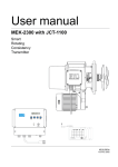
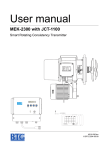
TCT-2301
Smart optical low consistency transmitter
Total Consistency
Transmitter
Sample
Enter
TCT-2300
M2007/3en
©BTG 2004
Disclaimer
The contents of this document are subject to revision without notice due to continued progress
in methodology, design, and manufacturing. BTG shall have no liability for any error or
damages of any kind resulting from the use of this document. ©BTG 2004.
BTG Pulp & Paper Sensors AB
P.O. Box 602
SE-661 29 Säffle
Sweden
Phone: +46 533 426 00
www.btg-group.com
Table of contents
1
Product introduction . . . . . . . . . . . . . . . . . . . . . . . . . . . . . . 1
1.1
1.2
1.3
1.3.1
1.4
1.5
1.6
1.7
1.8
2
Safety recommendations . . . . . . . . . . . . . . . . . . . . . . . . . 13
2.1
2.2
2.2.1
2.2.2
2.2.3
2.2.4
2.2.5
2.2.6
3
General . . . . . . . . . . . . . . . . . . . . . . . . . . . . . . . . . . . . . . . . . . . . . . . . . . . 1
Technical data . . . . . . . . . . . . . . . . . . . . . . . . . . . . . . . . . . . . . . . . . . . . . 2
Measuring principle . . . . . . . . . . . . . . . . . . . . . . . . . . . . . . . . . . . . . . . . . . 6
The Peak Method. . . . . . . . . . . . . . . . . . . . . . . . . . . . . . . . . . . . . . . . . . . 6
System description . . . . . . . . . . . . . . . . . . . . . . . . . . . . . . . . . . . . . . . . . . 8
Typical applications . . . . . . . . . . . . . . . . . . . . . . . . . . . . . . . . . . . . . . . . . . 8
Dimensions . . . . . . . . . . . . . . . . . . . . . . . . . . . . . . . . . . . . . . . . . . . . . . . 9
Type sign explanations . . . . . . . . . . . . . . . . . . . . . . . . . . . . . . . . . . . . . . 10
CE-declaration of conformity . . . . . . . . . . . . . . . . . . . . . . . . . . . . . . . . . 12
General safety recommendations . . . . . . . . . . . . . . . . . . . . . . . . . . . . . . 13
Product specific safety recommendations . . . . . . . . . . . . . . . . . . . . . . . . 14
General . . . . . . . . . . . . . . . . . . . . . . . . . . . . . . . . . . . . . . . . . . . . . . . . . 14
Selecting a transmitter model and assembly parts . . . . . . . . . . . . . . . . 14
Installing mounting details . . . . . . . . . . . . . . . . . . . . . . . . . . . . . . . . . . . 14
Installing the transmitter . . . . . . . . . . . . . . . . . . . . . . . . . . . . . . . . . . . . . 14
Installing the electronics box . . . . . . . . . . . . . . . . . . . . . . . . . . . . . . . . . 15
Starting up and servicing the transmitter . . . . . . . . . . . . . . . . . . . . . . . . 15
Installation instructions . . . . . . . . . . . . . . . . . . . . . . . . . . 17
3.1
3.1.1
3.1.2
3.2
3.2.1
3.2.2
3.2.3
3.2.4
3.2.5
3.3
3.3.1
3.3.2
3.3.3
M2044/0en
Before you start . . . . . . . . . . . . . . . . . . . . . . . . . . . . . . . . . . . . . . . . . . . . 17
Visual inspection . . . . . . . . . . . . . . . . . . . . . . . . . . . . . . . . . . . . . . . . . . 18
Installation and operating conditions . . . . . . . . . . . . . . . . . . . . . . . . . . . 18
Installing the transmitter . . . . . . . . . . . . . . . . . . . . . . . . . . . . . . . . . . . . . 19
Positioning the transmitter . . . . . . . . . . . . . . . . . . . . . . . . . . . . . . . . . . . 19
Probe clearance requirements . . . . . . . . . . . . . . . . . . . . . . . . . . . . . . . . 22
Sampling valve. . . . . . . . . . . . . . . . . . . . . . . . . . . . . . . . . . . . . . . . . . . . 22
Installing the ball valve assembly. . . . . . . . . . . . . . . . . . . . . . . . . . . . . . 23
Mounting the probe in the valve assembly. . . . . . . . . . . . . . . . . . . . . . . 24
Installing the electronics box . . . . . . . . . . . . . . . . . . . . . . . . . . . . . . . . . . 26
Choosing a site for the electronics box . . . . . . . . . . . . . . . . . . . . . . . . . 26
Electronics box design . . . . . . . . . . . . . . . . . . . . . . . . . . . . . . . . . . . . . . 28
Connecting the measuring probe to the electronics box . . . . . . . . . . . . 29
TCT-2302 Table of contents
©BTG 2004
I
3.3.4
3.3.5
3.3.6
3.3.7
3.4
3.4.1
3.4.2
3.4.3
3.4.3.1
3.4.4
3.5
4
Operating instructions . . . . . . . . . . . . . . . . . . . . . . . . . . . 43
4.1
4.1.1
4.1.2
4.1.3
4.1.4
4.2
4.2.1
4.2.2
4.2.3
4.3
4.3.1
4.3.1.1
4.3.2
4.3.3
4.3.3.1
4.3.3.2
4.3.3.3
4.3.3.4
4.3.4
4.3.5
4.3.6
4.3.7
4.4
4.4.1
4.4.2
4.4.3
4.4.4
II
External wiring dimensions . . . . . . . . . . . . . . . . . . . . . . . . . . . . . . . . . . 30
Main power supply connections . . . . . . . . . . . . . . . . . . . . . . . . . . . . . . 31
Transmitter input and output, measuring range connections . . . . . . . . . 34
Digital communication using the Hart®-protocol . . . . . . . . . . . . . . . . . . . 34
Probe cleaning system (option) . . . . . . . . . . . . . . . . . . . . . . . . . . . . . . . . 35
Dimensions and installation clearance. . . . . . . . . . . . . . . . . . . . . . . . . . 35
Installing the PCD-1000 upgrade kit . . . . . . . . . . . . . . . . . . . . . . . . . . . 36
Installing the PCD-1000 probe cleaning device . . . . . . . . . . . . . . . . . . . 40
Probe cleaning device connections . . . . . . . . . . . . . . . . . . . . . . . . . . . . 41
Controlling the cleaning device . . . . . . . . . . . . . . . . . . . . . . . . . . . . . . . 41
Checklist before start . . . . . . . . . . . . . . . . . . . . . . . . . . . . . . . . . . . . . . . 42
Starting the transmitter . . . . . . . . . . . . . . . . . . . . . . . . . . . . . . . . . . . . . . 43
Adjusting TAG / Serial no. . . . . . . . . . . . . . . . . . . . . . . . . . . . . . . . . . . . 44
Measuring range . . . . . . . . . . . . . . . . . . . . . . . . . . . . . . . . . . . . . . . . . . 44
Select measuring unit. . . . . . . . . . . . . . . . . . . . . . . . . . . . . . . . . . . . . . . 45
Setting measuring span . . . . . . . . . . . . . . . . . . . . . . . . . . . . . . . . . . . . . 45
Clear water adjustment . . . . . . . . . . . . . . . . . . . . . . . . . . . . . . . . . . . . . . 46
At start up. . . . . . . . . . . . . . . . . . . . . . . . . . . . . . . . . . . . . . . . . . . . . . . . 46
Selecting the correct ”mode” . . . . . . . . . . . . . . . . . . . . . . . . . . . . . . . . . 48
Adjustment of measuring gap angle. . . . . . . . . . . . . . . . . . . . . . . . . . . . 49
Calibration . . . . . . . . . . . . . . . . . . . . . . . . . . . . . . . . . . . . . . . . . . . . . . . . 51
General remarks on calibration . . . . . . . . . . . . . . . . . . . . . . . . . . . . . . . 51
Criteria for calibration . . . . . . . . . . . . . . . . . . . . . . . . . . . . . . . . . . . . . . . 51
General remarks on sampling . . . . . . . . . . . . . . . . . . . . . . . . . . . . . . . . 51
Calibration procedure. . . . . . . . . . . . . . . . . . . . . . . . . . . . . . . . . . . . . . . 52
Summary . . . . . . . . . . . . . . . . . . . . . . . . . . . . . . . . . . . . . . . . . . . . . . . . 52
Take sample. . . . . . . . . . . . . . . . . . . . . . . . . . . . . . . . . . . . . . . . . . . . . . 53
Load lab value . . . . . . . . . . . . . . . . . . . . . . . . . . . . . . . . . . . . . . . . . . . . 53
Calculate calibration. . . . . . . . . . . . . . . . . . . . . . . . . . . . . . . . . . . . . . . . 54
Multi-point calibration . . . . . . . . . . . . . . . . . . . . . . . . . . . . . . . . . . . . . . . 54
Calibration with given constants. . . . . . . . . . . . . . . . . . . . . . . . . . . . . . . 54
Calibration table . . . . . . . . . . . . . . . . . . . . . . . . . . . . . . . . . . . . . . . . . . . 55
Calibration curve . . . . . . . . . . . . . . . . . . . . . . . . . . . . . . . . . . . . . . . . . . 55
Other functions . . . . . . . . . . . . . . . . . . . . . . . . . . . . . . . . . . . . . . . . . . . . 56
Setting time constant (damping) . . . . . . . . . . . . . . . . . . . . . . . . . . . . . . 56
Setting alarm limits. . . . . . . . . . . . . . . . . . . . . . . . . . . . . . . . . . . . . . . . . 57
Offset adjustment . . . . . . . . . . . . . . . . . . . . . . . . . . . . . . . . . . . . . . . . . . 57
Manual loading of probe signal settings. . . . . . . . . . . . . . . . . . . . . . . . . 59
TCT-2302 Table of contents
©BTG 2004
M2044/0en
4.5
4.5.1
4.5.2
4.5.3
4.5.4
4.6
4.6.1
4.6.2
4.6.2.1
4.7
4.7.1
4.7.2
4.8
5
Evaluation and documentation of calibration . . . . . . . . . . . . . . . . . . . . . 60
Trend . . . . . . . . . . . . . . . . . . . . . . . . . . . . . . . . . . . . . . . . . . . . . . . . . . . 60
Documenting calibrations with printer . . . . . . . . . . . . . . . . . . . . . . . . . . 61
Documenting calibration using the ”back-up card” . . . . . . . . . . . . . . . . 64
Documenting calibration using a PC . . . . . . . . . . . . . . . . . . . . . . . . . . . 66
Electronics box display menu . . . . . . . . . . . . . . . . . . . . . . . . . . . . . . . . . 68
General information . . . . . . . . . . . . . . . . . . . . . . . . . . . . . . . . . . . . . . . . 68
Menu structure . . . . . . . . . . . . . . . . . . . . . . . . . . . . . . . . . . . . . . . . . . . . 69
How to change settings and collect samples . . . . . . . . . . . . . . . . . . . . 70
Hand-held Terminal SPC-1000 . . . . . . . . . . . . . . . . . . . . . . . . . . . . . . . . 75
Power supply . . . . . . . . . . . . . . . . . . . . . . . . . . . . . . . . . . . . . . . . . . . . . 76
Code protection . . . . . . . . . . . . . . . . . . . . . . . . . . . . . . . . . . . . . . . . . . . 78
Digital communication according to the Hart®-protocol . . . . . . . . . . . . . . 80
Service instructions . . . . . . . . . . . . . . . . . . . . . . . . . . . . . 81
5.1
5.1.1
5.1.2
5.1.3
5.1.4
5.2
5.2.1
5.2.2
5.2.3
5.2.4
5.2.5
5.2.6
5.2.7
5.2.7.1
5.2.8
5.2.9
5.2.9.1
5.2.9.2
5.2.10
5.3
5.3.1
5.3.2
5.3.3
5.3.4
5.3.5
M2044/0en
Maintenance planning and quality assurance . . . . . . . . . . . . . . . . . . . . . 81
Inspection of the accuracy/calibration of the consistency transmitter . . 81
Calibration recommendations . . . . . . . . . . . . . . . . . . . . . . . . . . . . . . . . 82
Maintenance of the transmitter. . . . . . . . . . . . . . . . . . . . . . . . . . . . . . . . 82
Functional description . . . . . . . . . . . . . . . . . . . . . . . . . . . . . . . . . . . . . . 83
Service electronics . . . . . . . . . . . . . . . . . . . . . . . . . . . . . . . . . . . . . . . . . 84
Electronics troubleshooting . . . . . . . . . . . . . . . . . . . . . . . . . . . . . . . . . . 84
Electronics card LED functions . . . . . . . . . . . . . . . . . . . . . . . . . . . . . . . 86
Function and testpoints of electronics card . . . . . . . . . . . . . . . . . . . . . . 87
Changing the electronics card . . . . . . . . . . . . . . . . . . . . . . . . . . . . . . . . 89
Change of power supply . . . . . . . . . . . . . . . . . . . . . . . . . . . . . . . . . . . . 91
Changing the front panel . . . . . . . . . . . . . . . . . . . . . . . . . . . . . . . . . . . . 92
Check analog out . . . . . . . . . . . . . . . . . . . . . . . . . . . . . . . . . . . . . . . . . . 92
Calibrate analog out . . . . . . . . . . . . . . . . . . . . . . . . . . . . . . . . . . . . . . . . 92
Checking communication to and from SPC-1000/A. . . . . . . . . . . . . . . . 93
Checking range inputs . . . . . . . . . . . . . . . . . . . . . . . . . . . . . . . . . . . . . . 94
Change range input using digital input (hardware) . . . . . . . . . . . . . . . . 94
Change range using software . . . . . . . . . . . . . . . . . . . . . . . . . . . . . . . . 94
Checking the alarm output . . . . . . . . . . . . . . . . . . . . . . . . . . . . . . . . . . 95
Service probe and valve arrangement . . . . . . . . . . . . . . . . . . . . . . . . . . 96
Pull out the probe from the ball valve. . . . . . . . . . . . . . . . . . . . . . . . . . . 96
Check clear water value and clean of probe . . . . . . . . . . . . . . . . . . . . . 97
Change the probe with fiber connection. . . . . . . . . . . . . . . . . . . . . . . . . 99
Replacing ball valve seals . . . . . . . . . . . . . . . . . . . . . . . . . . . . . . . . . . 100
Inserting the probe . . . . . . . . . . . . . . . . . . . . . . . . . . . . . . . . . . . . . . . . 101
TCT-2302 Table of contents
©BTG 2004
III
5.4
5.4.1
5.4.2
5.4.2.1
5.4.3
5.5
5.6
5.7
6
Parts list . . . . . . . . . . . . . . . . . . . . . . . . . . . . . . . . . . . . . . 111
6.1
6.2
6.3
6.4
6.5
IV
Service software . . . . . . . . . . . . . . . . . . . . . . . . . . . . . . . . . . . . . . . . . . 102
Software revisions . . . . . . . . . . . . . . . . . . . . . . . . . . . . . . . . . . . . . . . . 102
Troubleshooting functions . . . . . . . . . . . . . . . . . . . . . . . . . . . . . . . . . . 102
Alarm & diagnostics . . . . . . . . . . . . . . . . . . . . . . . . . . . . . . . . . . . . . . . 102
Software Fault feedback SPC-1000. . . . . . . . . . . . . . . . . . . . . . . . . . . 104
Evaluating calibrations . . . . . . . . . . . . . . . . . . . . . . . . . . . . . . . . . . . . . 106
Troubleshooting, general . . . . . . . . . . . . . . . . . . . . . . . . . . . . . . . . . . . 108
Maintenance of the cleaning system. . . . . . . . . . . . . . . . . . . . . . . . . . . 109
Probe . . . . . . . . . . . . . . . . . . . . . . . . . . . . . . . . . . . . . . . . . . . . . . . . . . 111
Valve arrangement . . . . . . . . . . . . . . . . . . . . . . . . . . . . . . . . . . . . . . . 113
TCT-2301 . . . . . . . . . . . . . . . . . . . . . . . . . . . . . . . . . . . . . . . . . . . . . . . 114
Cleaning device . . . . . . . . . . . . . . . . . . . . . . . . . . . . . . . . . . . . . . . . . . 116
Accessories . . . . . . . . . . . . . . . . . . . . . . . . . . . . . . . . . . . . . . . . . . . . . 117
TCT-2302 Table of contents
©BTG 2004
M2044/0en
1.1 - General
1
Product introduction
Total consistency transmitter
•
Measures total consistency, independent of varying content of filler
and fines, with a unique measuring method – enables accurate
consistency measurement
•
Virtually insensitive to flow variations and temperature changes –
for high accuracy and reproducibility
•
No moving parts and non-clogging probe design – gives low
maintenance costs
•
Simple calibration and documentation – provides easy start up and
usage
•
Simple installation – for low installation costs
•
Probe can be retracted without shutting down the process
1.1 General
The TCT-2301 is an in-line transmitter for measuring total consistency
of pulp suspensions in the range 0.01-3.5%.
Based on BTG's patented Peak Method (see section 1.3) of optical analysis, the TCT-2301 is virtually insensitive to variations in filler and fines
content, making it particularly suitable for use with recycled and mechanical pulp suspensions.
The transmitter is mounted in-line, without any special bypass arrangement, for optimized functioning of the control loop. The instrument's
unique probe, without electronic components, makes the transmitter insensitive to variations in temperature and vibration. The probe is connected to the wall-mounted electronics unit by an optical fiber.
An integrated fail-safe system means the probe can be installed and retracted safely without shutting down the process, even in high pressure
applications.
The transmitter's non-clogging and self-cleaning features ensure troublefree and accurate operation with easy maintenance.
M2007/3en
TCT-2301 Product introduction
©BTG 2004
1
1.2 - Technical data
The TCT-2301 employs modern microprocessor technology, including
fast data collection with a separate signal processor, digital data processing with advanced signal analysis.
Fig
1 Smart optical low
consistency
transmitter TCT2301 with SPC1000 hand-held
terminal
Total Consistency
Transmitter
Sample
Enter
TCT-2300
Terminal
The TCT-2301 is served by the SPC-1000 hand-held terminal, which
works not only with the TCT-2301, but also with all instruments in the
BTG family of smart transmitters.
The SPC-1000 can be connected at any point on the 4-20 mA output
signal loop. Communication with a DCS is by means of a superimposed
digitized signal according to a standard Hart® protocol. In addition, the
unit is prepared for fieldbus digital communication.
BTG has adopted the OPC communication standard, which enables any
OPC equipped system direct access to TCT-2301 transmitters.
1.2 Technical data
2
Type
TCT-2301 in-line smart optical consistency
transmitter for pulp slurries. One analog output for
total consistency.
Manufacturer
BTG, Säffle, Sweden
Measuring principle
Light scattering using the Peak-method.
Performed by light transmission of NIR, 880 nm
Measuring range
Total consistency 0.01 to max. 3.5% (0.1 - 35 g/l)
depending on fiber type and filler content
Measuring accuracy
± 0.004%
Repeatability
0.0001%
TCT-2301 Product introduction
©BTG 2004
M2007/3en
1.2 - Technical data
Process conditions
Process pressure
PN 16 (232 psi at 68 °F)
Media temperature
Max. 150ºC (302°F)
Max. ambient
temperature
Probe: 150ºC (302°F)
Electronics box: 50ºC (122°F)
Process pH
4-9
Storage temperature
Min. - 20ºC (70 °F)
Standardization
Standardization
Quality-assured in accordance with ISO 9001.
Designed in accordance with relevant CE standards.
See section 1.8: CE-declaration of conformity
Probe
M2007/3en
Mounting
Mounted through a ball valve assembly.
Material
Stainless steel to SS 2343, equiv. to ANSI 316, DIN
X5 CrNiMo 18.22, B.S.316 S16/En 58J
Connection
Optical connection to electronics box.
Weight
Probe 3.3 kg (7.2 lb)
Valve assembly approx. 3.8 kg (8.4 lb)
TCT-2301 Product introduction
©BTG 2004
3
1.2 - Technical data
Electronics Box
4
Supply voltage
Supply voltage 84 - 264 VAC, 50/60 Hz, max. 50 VA
- automatic setting. Output voltage 24 VDC,
regulated. Output power max. 40 VA, max. constant
power 1800 mA at an ambient temperature of 50°C
(122°F). Approved
according to UL, CSA, VDE.
Output signal - analog
4-20 mA. Isolated against mains supply / protective
earth. Built in insulation amplifier
Current limited to 21 mA.
Loop load signal: voltage supply / load
21.6 VDC / max. 1030 Ω
24 VDC / max. 1100 Ω
26.4 VDC / max. 1270 Ω
Min. (nom.) load for communication with hand-held
terminal 250 Ω.
Input signal - analog
0 / 4-20 mA
Output signal - digital
Superimposed signal over
4-20 mA current loop according to standard HART®
protocol and BELL 202 modem . Follows HART®
universal commands.
Power consumption
Max 600 mA incl. hand-held terminal
(excl. 200 mA) at 24 VDC
Measuring ranges
(analog)
Four separate, individually programmable, externally
connectable with binary-coded switch. Also
accessible via the communications link.
Input – digital
(measuring ranges)
2 x 2 optically isolated contact inputs.
Alarm function
(digital)
Optocoupler output. Provides alarm signal on low/
high LED curr./cons.level /internal temp.
Electronic Enclosure
Made of polycarbonate thermoplastic with a transparent cover. Metal-plated internally to protect against
interference.
Protection rating
IP65, NEMA 4x, UL, CSA
Weight
Electronics box 2.4 kg (5.3 lb)
TCT-2301 Product introduction
©BTG 2004
M2007/3en
1.2 - Technical data
Communications
Option 1:
Using the BTG SPC-1000 handheld terminal jacked
into the electronics box. The digital communication is
superimposed over the 4-20 mA current loop.
Option 2:
Directly with the DCS. See “Output signal - digital”.
Allows HART® universal commands.
Option 3:
RS-485 for connection to OPC-server. OPC program
provided by BTG. Note: Only for DCS/OCS systems
with OPC capabilities.
Option 4:
Prepared for fieldbus communication e.g. Profibus or
Fieldbus Foundation.
Signal transmission
10 m (33 ft) quartz glass optic fibers included,
protected in a flexible conduit.
On request 20 (66 ft), 30 (98 ft) and 40 m (131 ft).
Accessories
Hand-held terminal, SPC-1000
See data sheet D218.55
Smart Lab Sampler, SLS-1000
See data sheet D218.62
Documentation program for PC
Probe cleaning device: PCD-1000
See data sheet D2020.
PCD-1000 cleaning device (option)
M2007/3en
Weight
9.5kg/20.9lb including valve and probe.
Dimensions
See page 2.
Ambient temp.
50ºC/122 °F
Air supply/conn.
Filtered 4-7bar (58-102 psi).
Ø6/4mm (0.236/0.157)
Water conn.
Mechanically cleaned, 4-10bar (58-145 psi).
Inlet Ø8,5mm (0.335in)
Outlet Ø17mm (0.669in)
Supply voltage
24V DC supply from TCT-2301 electronics box.
Min. 4 x 0.75mm² (AWG18)
TCT-2301 Product introduction
©BTG 2004
5
1.3 - Measuring principle
1.3 Measuring principle
1.3.1
Fig
2 Operating principle
1
2
3
4
5
6
7
8
9
The Peak Method
3
2
1
4
Pulp flow
Measuring gap with light beam
Optical fiber from light source
Optical fiber to detector
Amplifier
Digital signal processor
Microprocessor
Input signals
Output signals
4
6
5
1
PEAK
DC
2
7
8
9
3
The TCT-2301 employs the patented peak method for measuring total
consistency of pulp suspensions. This technology is based on the fact that
suspensions contain both large and small particles. Large particles are
typically fibers and small particles are fillers and fines.
Close study of a suspension sample shows that the high number of small
particles in the suspension remains relatively constant over time. On the
other hand, there are far fewer large particles and their number varies significantly over time.
The large particles form a relatively transparent network, within which
the small particles move freely. A narrow light beam directed through the
suspension is generally affected by both the large and small particles.
There is however an interval when only small particles affect the light
beam, and this is know as the "Peak" period.
During the other time periods, the light beam is affected by both the large
and small particles. Fig 2 and fig 3 illustrate this principle.
In fig 2, a light beam passes through the pulp flow (1). The transmitted
light is detected by a photo detector. The detector signal is amplified (5)
and then treated by the signal processor (6).
6
TCT-2301 Product introduction
©BTG 2004
M2007/3en
1.3 - Measuring principle
Three signals are computed by the detector signal: The mean value, VDC,
the peak value, VP and the AC-component, VAC. Typical time graph
showing the detector signal is displayed in fig 3.
The total consistency is obtained by adding the further treated VP and the
VDC values.
Fig
3 Output signal
VCW
Clear water
VP
Peak value
VDC
Direct current signals
VAC
Alternating current signals
TC
Total Consistency
Light transmission
Volts
TC
Time
M2007/3en
TCT-2301 Product introduction
©BTG 2004
7
1.4 - System description
1.4 System description
Fig
4 Typical control loop for
consistency control of the TCT2301
2
Total Consistency
Transmitter
Enter
Sample
TCT-2300
1
2
3
4
5
6
7
8
9
Measuring probe
Electronics box
Hand-held terminal SPC-1000
3/4 wire system for analog output
Controller/recorder (DCS)
Dilution water valve
Pulp chest with sufficient mixing
Stock pump
BTG sampling valve type MPS-1000
Terminal
9
3
4
5 CRC
1
7
6
8
The system consists of a probe (1) connected by an optical fiber to an
electronics box (2) The probe contains only optical fibers. A ball valve
arrangement that is welded to the pipe system make it possible to remove
the probe without interrupting the process.
The electronics box contains electronics card, power supply, electrical
and optical connections. To set up the transmitter a hand-held terminal
(3) type SPC-1000 must first be connected (see fig 4).
The hand-held terminal allows the operator to set up and monitor the system. It includes a liquid crystal display (LCD) with a touchscreen keypad.
1.5 Typical applications
8
•
Control of flotation systems or wash stages for de-inking of
recycled fibers
•
Control of screening and cyclone cleaning processes
•
Monitoring of TMP/CTMP steam and hot-water recovery
systems
TCT-2301 Product introduction
©BTG 2004
M2007/3en
1.6 - Dimensions
1.6 Dimensions
Fig
5 TCT-2301 Dimensions
1
469
18.5"
M2007/3en
Min Ø100
4"
Ø50
2”
251
9.9"
121
4.8"
121
4.8"
53
2.1"
2
108
4.3"
1 Electronics box
2 Probe with retraction
system
300
12"
TCT-2301 Product introduction
©BTG 2004
9
1.7 - Type sign explanations
1.7 Type sign explanations
Fig
6 Type sign
1
2
3
4
5
6
7
8
9
10
11
12
Manufacturer
CE-marking
C-TIC marking
ETL-marking
Warning sign
Type specification
Voltage
Apparent power
Installation category
Frequency
Manufacturing number
Factory Identification
1
2
BTG Pulp & Paper Sensors AB
Box 602
661 29 Säffle
SWEDEN
www.btg-group.com
6
TYPE
7
VOLTAGE
8
APPARENT POWER
4
5
N1619
NO
TCT-2301
FREQUENCY
50-60 Hz
100-240 VAC
50 W
3
INSTALLATION CATEGORY
III
9
10 11
FACTORY IDENTIFICATION
12
1. Manufacturer
2. CE-marking
Always refer to the type
sign when ordering spare
parts.
The TCT-2301 is approved according to CE directives.
3. CSA-marking
The TCT-2301 electronics box is approved according to Australian CTIC N1619 directives.
4. ETL-marking
The TCT-2301 electronics box is approved by ETL
5. Warning sign
The device is designed for industrial use. Installation, handling and service must only be carried out by trained and authorized personnel and according to relevant standards. Read the manual for detailed information
and pay special attention to the warning signs!
10
TCT-2301 Product introduction
©BTG 2004
M2007/3en
1.7 - Type sign explanations
6. Type specification
7. Voltage
Automatically adjustable between 100-240V AC.
8. Apparent power
According to CE directive. Max. continuous output.
9. Installation category
According to CE directive. Resistant to transients.
10.Frequency
The unit operates both 50 and 60 Hz.
11.Manufacturing number
BTG internal product identification number.
12.Factory identification
M2007/3en
TCT-2301 Product introduction
©BTG 2004
11
1.8 - CE-declaration of conformity
1.8 CE-declaration of conformity
CE-Declaration of Conformity
According to EN 45014
Manufacturer´s Name
Manufacturer´s Address
declares that the product:
Product Name
Model Number
complies with the amendments and
requirements of the:
and conforms with the following product
standards and PED conformity assessment
procedure
Safety
LVD
BTG Pulp & Paper Sensors AB
P.O. Box 602 S- 661 29 SÄFFLE, Sweden
Total Consistency Transmitter
TCT-2300/2301/2302/with FCI-1000
Machinery Directive 89/392/EEC
Low Voltage Directive 73/23/EEC
EMC Directive 89/336/EEC
PED Directive 97/23/EEC
EN 292/1-2
EN 61010-1
PED
Pressure equipment for piping.
In accordance to Article 1,
Table 9, art.3 (3), Annex II
(Sound eng. practise)
Must not bear CE-marking
EMC
EN 50081-2 Aug.93
EN 61000-6-2 Apr.02
ISO 9001
monitored by
Lloyd`s Register Quality Assurance
Quality System
Säffle
Mars 2002
Tom Gustavsson, MD
12
TCT-2301 Product introduction
©BTG 2004
M2007/3en
2.1 - General safety recommendations
2
Safety recommendations
2.1 General safety recommendations
Installation, handling and service must only be carried out by trained and
authorized personnel and according to valid standards.
See section 1.2: Technical
data for detailed
information.
•
The product is designed for industrial use.
•
Installation category: III
•
Shock protection: Class I
•
Pollution degree: 2
•
IP Code: IP65 / NEMA 4X
•
The product complies with the EEC directives and relevant
standards:
To meet the EMC directive the following precautions have to be
taken:
1. All wiring has to be shielded.
Power supply electronics:
shielded, coverage≥ 80%
Interface cable:
coverage 100% aluminum
2. All units are tested as a complete system to conform with relevant CE directives and their standards.
When using the unit in other combinations, BTG cannot guarantee
the CE directive conformity.
The unit in combination with customer installed external devices
may conform with EMC and safety requirements when properly
installed and using an adequate CE marked equipment.
The system operator is responsible for the CE directive conformity. Conformity must be checked by inspection.
•
M2007/3en
Take precautions when handling equipment in pressurized/hot lines.
TCT-2301 Safety recommendations
©BTG 2004
13
2.2 - Product specific safety recommendations
2.2 Product specific safety recommendations
These safety recommendations are based on a risk analysis carried out in
accordance with the requirements of the machinery and low voltage directive in order to comply with European standards for CE marking.
2.2.1
General
The possibility of risk from a consistency transmitter in operation only
arises when covers have been removed during installation and servicing,
due to hazardous electrical voltage.
Read these safety recommendations before installing the transmitter.
Follow the recommendations when installing the transmitter, starting up
and servicing. Use warning signs for safety information!
These safety recommendations apply to the transmitter fitted with an AC
powered electronics box. Mounting parts, such as the weld-in studs, are
dealt with in accordance with the pressure vessel standards of the respective countries.
! For good personal and functional safety: Use only parts which
have been manufactured or approved by BTG.
2.2.2
Selecting a transmitter model and assembly
parts
Pressurized parts must be suited to the current maximum pipe pressure in
relation to temperature. Select a material for the parts that are in contact
with the medium so that corrosion does not occur.
2.2.3
Installing mounting details
Welding and subsequent inspection should take place in accordance with
current standards and regulations.
Be sure that the pipe is
empty before opening it!
14
2.2.4
Installing the transmitter
•
Construct a platform or use safe and approved ladders if the
transmitter is located high up. This platform will make it easier to fit
and start-up the transmitter and carry out service in the future.
•
The rubber quality of the transmitter seal (O-ring) should be selected
to suit the current medium. The O-ring supplied is suitable for this
application.
•
Screw the valve assembly firmly onto the weld-in stud.
TCT-2301 Safety recommendations
©BTG 2004
M2007/3en
2.2 - Product specific safety recommendations
Check that the screws/nut
holding the valve/probe
together are mounted and
properly tightened.
•
Install the probe into the valve assembly. Fit the two screws locking
the probe in place. Check that these screws are properly tightened, as
well as the four screws holding the valve together. See section 3.2.5:
Mounting the probe in the valve assembly for details.
•
When the probe has been installed, carry out test pressurization using
water in the pipeline. The correct test pressure depends on standards
and regulations in each country. In some lines for which inspection
is required, a pressure test must be carried out before the product can
be commissioned.
2.2.5
DANGER!
High voltage inside the
electronics box.
Connections may only be
carried out by qualified
personnel.
Installing the electronics box
A hazardous voltage is used to drive the electronics box. The electronics
box may only be connected by a qualified electrician in accordance with
instructions. The earth ground should be connected correctly and
checked.
It should be possible to switch off the voltage in the distribution centre,
for example. A clear warning, such as a sign, should let other people
know that work is in progress and the switch must not be touched.
•
Use only metallic cable fittings with shield connection for the
electronics box.
2.2.6
Starting up and servicing the transmitter
Read through the following points before starting up and servicing the
transmitter. Bear also in mind that the points mentioned above contain
important information for these operations.
To prevent electrical shock
— connect the protective
earth
PE properly.
M2007/3en
•
Before removing the probe from the valve assembly, check carefully
that the valve is closed. Hot or corrosive liquid flowing out under
pressure may cause serious chemical burn injuries!
•
Take care when opening the cover of the electronics box with builtin power supply unit. It contains live parts that may cause electric
shocks. Live parts are protected against normal contact provided that
connections are made correctly.
•
When the probe is exposed to dangerous basic or acidic corrosive
media, it should be removed from the pipeline regularly for
inspection. Replace any damaged seals. If the probe’s pressurized
parts have corroded, check that the material is correct for the
application. Leakage may cause personal injury or damage to
equipment due to corrosion or burning!
TCT-2301 Safety recommendations
©BTG 2004
15
2.2 - Product specific safety recommendations
16
TCT-2301 Safety recommendations
©BTG 2004
M2007/3en
3.1 - Before you start
3
Installation instructions
3.1 Before you start
This section contains instructions for planning and implementing the installation of the BTG TCT-2301 in-line consistency transmitter.
If you are in doubt whether the model you plan to install is the same
in all respects as the model described in this manual, or you have any
questions about installation, please contact your BTG sales engineer.
When you are satisfied that your TCT-2301 has been correctly installed
and are ready to power up the system for calibration, please turn to section 3.5: Checklist before start.
Double check items in the list before powering up. This list can help ensure a trouble-free initialization of your system.
This section introduces the essential components of the system.
This introductory section is followed by:
section 3.2: Installing the transmitter
This section contains detailed instructions for installing the transmitter.
section 3.3: Installing the electronics box
This section describes how to connect mains power supply, inputs
and outputs.
section 3.4: Probe cleaning system (option)
This section describes how to install the PCD-1000.
section 3.5: Checklist before start
When you are satisfied that your TCT-2301 has been correctly installed and are ready to power up the system for calibration, please
turn to this section.
M2007/3en
TCT-2301 Installation instructions
©BTG 2004
17
3.1 - Before you start
3.1.1
Visual inspection
This product was inspected and tested prior to shipment. However, even the
best products can sustain shipping damage that will only be seen if the
product is inspected. Before proceeding check the probe assembly, the
hand-held terminal, and the electronics box for shipping damage. Look
for loose screws, wires or electronic components.
3.1.2
For safety precautions
please refer to section 2.
Product type sign
explanations see section 1.7
Installation and operating conditions
The Consistency Transmitter is a precision tool and must be properly installed to ensure reliable service. Please, read the following instructions
and user information before installing the transmitter.
The transmitter is manufactured to provide accurate and reliable measurements over a long period of time.
! Correct installation will ensure maximum operating life of the
transmitter.
18
TCT-2301 Installation instructions
©BTG 2004
M2007/3en
3.2 - Installing the transmitter
3.2 Installing the transmitter
Fig
7 Recommended
distance between
pump and consistency
transmitter.
Can also be placed in
the cone after the
pump. Turbulent flow
will give the best
measuring conditions
for this type of
transmitter.
0.1m
(4 in)
Warning: To avoid
personnel injuries, burning
3.2.1 Positioning the transmitter
injuries, aggressive
chemical injuries etc., it is To make an accurate and reliable measurement it is critical to find the correct
extremely important that installation point.
the pipe is depressurized
Fig 4 on page 8 shows a typical installation. Your BTG sales engineer
and empty before opening
can help you select the location that will give the best results in relation
it for installation or
to your control strategy.
removal of the equipment.
! Minimum recommended flow velocity: 1 m/s (3.3 ft/s).
! To minimize time lag, locate the probe close to the dilution point.
Fig
8 Installation of the
probe in relation to
different pumps
M2007/3en
TCT-2301 Installation instructions
©BTG 2004
19
3.2 - Installing the transmitter
Fig
9 Installation of the
probe near a pipe
elbow
0°
! Alternative A is the
most suitable. Avoid
alternative C.
90°
TCT2300
Flow
0° Direction
A
B
C
Important recommendations:
1. Do not install the probe where there is trapped air or where air may
be sucked into the process.
2. If there is risk of flocculation in the pulp suspension, install the probe
where the flow rates exceeds 1 m/s (3.3 ft/sec).
This applies particularly to long-fiber pulp suspensions.
3. Install the probe so that it is protected from direct mechanical damage.
4. Protect the probe from heavy vibration such as cavitation or unbalanced pumps. One method is to install a rubber bellows in the line.
20
TCT-2301 Installation instructions
©BTG 2004
M2007/3en
3.2 - Installing the transmitter
If the probe is installed in a horizontal pipe, always install it at the side
of the pipe rather than at the top or bottom to avoid problems with
trapped air or dirt. Remember the clearance requirements, so that the
probe can be mounted in the ball valve arrangement.
5. The ball valve assembly should be mounted at a 90° angle to the pipe
line.
6. The ball valve assembly should be mounted on the side of the pipe
line. A small angle downwards makes it possible for the pulp to evacuate when the probe is retracted and also makes the insertion of the
probe easier. See fig 10 below.
Fig 10 Installation of the
probe in a horizontal
pipe.
M2007/3en
TCT-2301 Installation instructions
©BTG 2004
21
3.2 - Installing the transmitter
3.2.2
Probe clearance requirements
The installed length of the probe, inserted into the ball valve arrangement, is approximately 470 mm (18.5 in) long. You will also need a minimum distance of 300 mm (11.8 in) to remove the probe from the pulp
line. Leave sufficient room around the probe to perform this task.
The probe weighs approximately 3.3 kg (7.2 lbs).
108
4.3"
121
4.8"
Min Ø100
4"
Ø50
2”
469
18.5"
251
9.9"
121
4.8"
53
2.1"
Fig 11 Probe. Dimensions in
mm/in
300
12"
! Remember to provide access room for an operator, as well as the
full depth of the probe assembly and the electronics box.
3.2.3
Sampling valve
The sampling valve should be installed close to the transmitter. This
helps to ensure that the laboratory sample is representative of the sample
measured by the transmitter.
Installing an appropriate BTG sampling valve, will ensure reliable results.
! Install the sampling valve up or downstream of the transmitter but
not closer than 0.5 m (1.5 ft) to the transmitter to avoid
disturbances.
22
TCT-2301 Installation instructions
©BTG 2004
M2007/3en
3.2 - Installing the transmitter
3.2.4
Installing the ball valve assembly
1. Mark the position on the pipe wall where the probe is to be located.
2. Drill a 50 mm / 2” inch hole in the pipe at the marked position.
3. Adapt the welded stud profile to the pipe. Adjust length according to
fig 12.
Fig 12 Mounting the flanged
weld-in stud
4. Make sure the weld-in stud is aligned to the pipe. See fig 12.
5. Weld the stud to the pipe. A full penetration weld must be used.
! If the probe is delivered with a PCD-1000, refer to section 3.4: Probe
cleaning system (option).
6. Mount the ball valve arrangement. The slot for the crank handle must
be located upwards since there is a scale on the probe that must be
adjusted before the probe is mounted.
Fig 13 Mounting positions of
the probe.
M2007/3en
TCT-2301 Installation instructions
©BTG 2004
23
3.2 - Installing the transmitter
3.2.5
Mounting the probe in the valve assembly
1. Make sure the measuring gap on the probe is at a 45° angle to the
pulp flow. The angle may have to be changed after start-up.
Fig 14 Measuring gap angle
adjustment
2a
1 Punch mark
2 Pulp flow direction
2
0°
45°
2b
00
90°
2
-2
3
45°
0°
T
TC
1
0°
45°
45°
45°
1
2c
45°
-2
3
00
90°
0°
T
TC
1
2d
If the angle is not correct, loosen the three screws that hold the probe
flange and adjust the probe so that the punch mark on the probe is at
the 45° line on the scale. Tighten the three screws properly. A suitable allen key is included in the delivery.
! Angles other than 45° can be used in some installations. See
section 4.2.3: Adjustment of measuring gap angle.
Fig 15 Probe scale
adjustment
24
TCT-2301 Installation instructions
©BTG 2004
M2007/3en
3.2 - Installing the transmitter
2. Apply a small amount of o-ring lubricant to the o-ring in the ball
valve housing.
3. Make sure the o-ring on the probe flange is mounted.
4. Insert the probe, using a twisting motion to get the probe tip to enter
the o-ring. Place the flexible insertion screw in the correct position
and make sure the hook with its locking device is in the correct position and secured.
Fig 16 Mounting the probe in
the valve assembly
5. Open the ball valve and insert the probe by cranking the handle.
6. Secure the probe in inserted position with the two security screws
Avoid getting O-ring
lubricant on the measuring
gap
! Secure the two security screws properly
7. When removing the probe, reverse the above procedures.
M2007/3en
TCT-2301 Installation instructions
©BTG 2004
25
3.3 - Installing the electronics box
3.3 Installing the electronics box
3.3.1
Choosing a site for the electronics box
! Locate the electronics box close to the transmitter/ sampling valve
to achieve a correct and convenient connection of the SPC-1000
hand-held terminal for calibration and monitoring.
The hand terminal SPC-1000 can be positioned in a holder, located close
to the electronics box. See fig 20.
Fig 17 Dimensions of the
electronics box
50
2"
Fig 18 Electronics box
clearances
300
12"
Sample
Enter
50
2"
200
8"
Terminal
Install the box in a position where it will be protected from mechanical
damage.
26
TCT-2301 Installation instructions
©BTG 2004
M2007/3en
3.3 - Installing the electronics box
BTG recommends that a roof or overhang is located above the electronics
box to protect it against spray and pulp. If the box is located outdoors a
roof will protect the unit from direct sunlight which can cause excessive
operating temperatures. If possible, the SPC-1000 mounted in its holder
should also be protected.
Fig 19 Protecting roof for
Electronics box
200
8"
300
12"
75°
The electronics box is equipped with three attachment lugs and should be
bolted to a wall.
Fig 20 Wall mounted
brackets positioning
the SPC-1000, for
easier operation
Fig 21 SPC-1000 positioned
in the brackets
M2007/3en
TCT-2301 Installation instructions
©BTG 2004
27
3.3 - Installing the electronics box
3.3.2
Electronics box design
! Electronics boxes manufactured by BTG are designed to meet
personal safety and interference requirements under the European
CE directive and Canadian CSA requirements.
The plastic enclosures are made of polycarbonate thermoplastic.
They are metal-plated internally to protect against interference.
Metal screw caps for attaching connection cable shield are an important part of the interference suppression system.
The electronics box is supplied with an external jack connection
for the hand terminal, SPC-1000/A, and the Smart Lab Sampler,
SLS-1000.
Fig 22 Electronics box
1 Display
2 Operating buttons
3 SPC-1000/A
connection
4 LEDs
5 Power switch
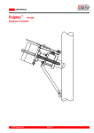
6 Fuses
7 Electrical connections
8 Optical fiber connection
1
1.30% 12.53mA
2
3
Total Consistency
Transmitter
Enter
Sample
TCT-2300
4
5
F1
F3
F2
7
N
L PE
IN1
IN2
ALARM
MODE
PWR OK
DO1
DO2
Di1
6
Terminal
+24 GND +AOUT1- +AOUT2- IN1 IN2 GND +AIN- +ALARM- COM+DO1 DO2 DI1
GND A B
GND A B
8
28
TCT-2301 Installation instructions
©BTG 2004
M2007/3en
3.3 - Installing the electronics box
3.3.3
Connecting the measuring probe to the
electronics box
The optical connection is on the lower right side of the electronics box.
Remove the protective cover on the electronics box connector, and on the
optical connector on the probe. Note the position for the optical connector in fig 23. The connector fits only in one position. Make sure the Oring is mounted on the probe connector. Push the connector all the way
in. Try to turn the connector (this should not be possible) to verify that it
is in the end position. Secure the connection properly with the plastic nut.
Coil the extra optical fiber and secure it under the electronics box in order
to avoid the risk of mechanical damage.
! Make sure the optical connector from the probe is positioned
correctly and pushed all the way in before securing it with the
plastic nut.
Fig 23 Optical connection
1
2
3
4
5
6
7
8
Aluminum washer
Electronics box
Rubber sealing
Electronics box optical
connector
O-ring
Plastic nut
Probe optical connector
Optical fiber to probe
! The optical fiber must not be coiled with a radius smaller than
50mm (2 in) Locate it so that is protected and not subject to risk of
mechanical damage.
The standard optical fiber is 10 m (33 ft). It is possible to use optical fiber
up to 40 m (131 ft) long. Contact your BTG sales engineer for more information regarding optional fiber lengths.
! Do not cut the optical fiber.
M2007/3en
TCT-2301 Installation instructions
©BTG 2004
29
3.3 - Installing the electronics box
3.3.4
External wiring dimensions
BTG recommends properly dimensioned wire, shielded and twisted in
pairs, for connection between the electronics box and external equipment. See also section 2.1: General safety recommendations.
Power supply cable:
Electronics box with built-in power supply unit:
• Shielded (80%)
• 3 x 0.75 mm2 (3 x AWG18) with PE.
• Cable diameter: 7,5-13 mm
• In accordance with the IEC 227/245 standard
Output signal cables:
• Shielded (80%), twisted pair
• Min. 2 x 0.3 mm2 (2 x AWG24).
The size typically used is 2 x 0.75 mm2 (2 x AWG18)
• Cable diameter: 6-11 mm
Range select cable:
• Shielded (80%), twisted pair
• Min. 2 x 0.3 + 2 x 0.3 mm2 (2 x AWG24 + 2 x AWG24)
• Cable diameter: 6-11 mm
Alarm/AUX-in cable:
• Shielded (80%), twisted pair
• Min. 2 x 0.3 mm2 (2 x AWG24)
• Cable diameter: 6-11 mm
! Signal cables can be combined to one or two cables.
30
TCT-2301 Installation instructions
©BTG 2004
M2007/3en
3.3 - Installing the electronics box
3.3.5
DANGER!
High voltage within the
electronics box.
Connections may only be
carried out by qualified
personnel
To prevent electrical shock
- connect the protective
earth properly
PE
Main power supply connections
Important: Before installation, ensure that:
1. All power to the system has been turned off.
2. The 2AT fuses on the main card, marked F2 and F3, are installed.
The conduit for the power supply to the electronics box should be
installed in the leftmost hole.
Wiring the main power supply screw terminal:
The earth wire must be connected to the terminal indicated by the
protective earth symbol
PE.
See fig 26 on page 32.
3. Strip the cable covering (insulation) to expose the shortest possible length of the connection wires.
! Unshielded long, looped wires may cause interference! This can
interfere with the signal!
4. Once the wires are inserted, tighten the screws to secure them.
Mount the connector in its position.
5. To ensure interference-free operation a shielded cable should be
used. Make sure the shield is correctly connected - fig 24.
Fig 24 Connection of cable
shield, in special cable
screw cap (metal)
1 Connection cable for power
supply, measuring range
etc.
2 Nut
3 Sealing ring
4 Insert ring
5 Cable shield
6 Socket
7 Free wires
7
6
5
4
3
2
1
! Tighten nut fully for
maximum contact for
the shield.
6. Turn on the main power supply.
M2007/3en
TCT-2301 Installation instructions
©BTG 2004
31
3.3 - Installing the electronics box
Fig 25 Power connections –
electronics box
Total Consistency
Transmitter
1 Fuses
2 Power connection
100-240 V AC
3 Power switch
4 24 VDC out
4-20mA output signals
Range setting
0-20 mA input signals
Alarm
5 LEDs
6 Digital signals
7 Fieldbus
8 RS-485
9 Optical fiber connection
10 SPC-1000/A
connection
Enter
Sample
TCT-2300
IN1
IN2
ALARM
MODE
PWR OK
DO1
DO2
Di1
Terminal
F1
F3
F2
N
+24 GND +AOUT1- +AOUT2- IN1 IN2 GND +AIN- +ALARM- COM+DO1 DO2 DI1
L PE
2
1
GND A B
3
5
4
6
GND A B
7
8
9
10
7. Switch on the main power on the electronics card. The power
LED should now light up. See fig 25. If not, check first the connections and then the 2 AT fuse for the power supply located inside the electronics box.
Check the 24 V DC at terminal +24, GND - fig 26.
-
A IN
IN1
IN2
GND
+
GND
ALARM
-
+
COM DO1
+
-
DO2
DI1
GND
A
B
S = Shield connected to cable-gland
* = Not used for TCT-2301
PCD-1000 option
OUT 1 4-20mA min 250ohm
PCD-1000 option
B
Field bus
S
S
A
RS485
Alarm
+
-
Aux In
A OUT 2
+
Range B
A OUT 1
A Out 2 *
+24V GND
PE
Range A
L
Power to
external
equipment
N
A Out 1
Line power
100-240 VAC
TCT-2301
Fig 26 Wiring diagram for
electronics box
TCT-2301
0=
1=
RANGE 1
RANGE 2
RANGE 3
RANGE 4
A
0
1
0
1
B
0
0
1
1
Notes on fig 26:
32
•
An external 2-pole switch close to the electronics box is required.
•
Standard output signal 4-20 mA with superimposed digital signal
according to Hart®-protocol. See section 3.3.7.
•
Four different measuring ranges (RANGE 1-4) are available. The
setting of the respective measuring range is arranged via a binary
code switch (range setting - see fig 26 switch A/B) or DCS.
•
The unit is prepared for fieldbus. To access the communication an
additional circuit card is required.
TCT-2301 Installation instructions
©BTG 2004
M2007/3en
3.3 - Installing the electronics box
Explanation for fig 26 TCT-2301 wiring diagrams.
Terminal
Function
N
Neutral
L
Phase 85-264 V AC, 47-440 Hz, power fuse 2AT
PE,
Protective earth
+24
+24V DC (to optional PCD-1000)
GND
Ground, 0V DC (to optional PCD-1000)
AOUT 1+
Output signal 4-20mA
AOUT 1-
Output signal 4-20mA
AOUT 2+
Not used
AOUT 2-
Not used
IN1
Range A for external range setting
IN2
Range B for external range setting
GND
Ground, Common for range A and B
AIN+
Input signal 0-20mA (from external equipment)
AIN-
Input signal 0-20mA (from external equipment)
ALARM+
Alarm from TCT
ALARM-
Alarm from TCT
COM +
Common (to optional PCD-1000)
DO 1
Digital output signal 1(to optional PCD-1000)
DO 2
Digital output signal 2
DI 1
Digital input signal 1
RS-485 GND
Ground
RS-485 A
Serial connection
RS-485 B
Serial connection
Fieldbus GND Ground
Fieldbus A
Fieldbus connection
Fieldbus B
Fieldbus connection
! To enable communication using the Hart®-protocol, and use of a
hand-held terminal, a 250 Ω min. circuit resistance is required.
A 250 Ω resistor is connected at terminals A OUT+ and A OUT- at
the factory.
Remove the resistor when connecting the output signal.
M2007/3en
TCT-2301 Installation instructions
©BTG 2004
33
3.3 - Installing the electronics box
3.3.6
Transmitter input and output, measuring
range connections
Important: Before installation, ensure that:
1. The mains power supply is connected according to section
3.3.5.
2. The mains power is turned OFF.
To ensure disturbance-free
operation it is essential
that cable shields are
correctly connected in the
cable screw caps - see fig
24.
3. To ensure interference-free operation, the cable fittings should
be adapted for shielded cables. See fig 24 on page 31.
Wiring the signal screw terminals:
The screw terminals are in the lower section of the connection terminal
fig 25 on page 32.
4. Strip the cable covering so the shield is exposed. Use the shortest
possible length of the connection wires.
! Unshielded long, looped wires may cause signal interference! Strip
only enough insulation from the wires to insert them. The wires are
connected according to fig 26 on page 32. Once the wires are
inserted, tighten the screws to secure them.
5. Tighten the nut fully to ensure a good contact for the shield.
6. Turn on the power and test the functionality.
3.3.7
Digital communication using the Hart protocol
®
Certain functions are available as a digital signal under the Hart®-protocol and BELL 202 modem standard.
! The transmitter complies to Hart®-protocol standard requirements.
A BTG handheld terminal is used to set and calibrate the
transmitter. As this unit provides additional functions not covered
by the Hart®-protocol, a standard Hart®competitive terminal offers
only limited functionality.
Communication takes place as a superimposed signal over the 4-20 mA
output signal loop.
! For details, please contact the Hart® Communication Foundation or
BTG.
34
TCT-2301 Installation instructions
©BTG 2004
M2007/3en
3.4 - Probe cleaning system (option)
3.4 Probe cleaning system (option)
This section describes how to install the PCD-1000 probe cleaning device. The system can be delivered as a separate unit for rebuilding existing units or together with a complete TCT-2301 transmitter. If the
cleaning system is ordered with the TCT-2301 the probe will be mounted
in the cleaning device at the BTG factory. The installation method is described for both cases.
Fig 27 PCD-1000 probe
cleaning device
3.4.1
Dimensions and installation clearance
Ensure that there is sufficient clearance to remove the probe and cleaning
device from the valve assembly.
Fig 28 PCD-1000 dimensions
700
28"
Min 300
12"
92
3,6”
133
5,3"
~550
22"
140
5,5"
Min 100
4"
The installed device is approx. 700 mm (28 in) long. You will need at
least 300 mm (12 in) to remove the device from the valve arrangement.
The cleaning device weighs approx. 9.5 kg (21 lbs) including the TCT2301 probe.
M2007/3en
TCT-2301 Installation instructions
©BTG 2004
35
3.4 - Probe cleaning system (option)
3.4.2
Installing the PCD-1000 upgrade kit
This section describes how to upgrade an existing TCT-2301 transmitter
with the probe cleaning device PCD-1000/A (accessory).
! Make sure the pipe is empty and pressureless before starting the
installation.
1. Remove the TCT-2301 probe from the existing valve arrangement,
note the measuring angle, that is, the measuring gap angle in relation
to the pulp flow.
21
2. Disconnect the optical connection from the TCT-2301 electronics
box. Protect the optical connection with a plastic tube or similar.
3. Remove the handle and the flange with the angle scale.
20
4. Place the cleaning device on a workbench with the valve facing
downwards.
Fig 29 Sequence of installing
the PCD-1000
upgrade kit
! To keep all O-rings in position during disassembly/assembly,
always place the cleaning device in a upright position with the
valve facing downwards.
8 7 6 5 4
3
2 1
9
5. Unscrew and remove the screw (2) and the nut (1).
6. Unscrew and remove the nuts (4) and the washers (5).
7. Loosen the air tube (9) from the nipple and remove the rear cylinder
flanged end (6) together with the protective sleeve (3).
Keep track of the O-rings (7 and 8).
36
TCT-2301 Installation instructions
©BTG 2004
M2007/3en
3.4 - Probe cleaning system (option)
10 11 12
13
14
8. Remove cylinder flanged end (12) and pull out piston with guiding
rod (13). Keep track of O-ring (11) and guide ring (10).
Alternatively, pull out the cylinder flanged end and piston in one
piece and separate them afterwards.
9. Remove the rubber bushing (14) from the guiding rod.
15 16
17
10. Loosen the screws (16) and separate the piston (15) and guiding rod
(17) from each other.
18 19 19
17
11. Insert the probe (18) in the piston (15) and the fiber cable in the guiding rod (17).
12. Make sure that the screw hole on the edge of the guiding rod is
aligned with the measuring gap on the probe. Then join the piston
and the guiding rod with the screws (16). Do not forget the O-rings
(19).
13. Put the accompanying rubber bushing (14) over the fiber cable and
push it into the tip of the guiding rod.
M2007/3en
TCT-2301 Installation instructions
©BTG 2004
37
3.4 - Probe cleaning system (option)
14. Push the probe and piston into the cylinder. Make sure the guide ring
(10) is in position.
20
21
15. Mount the cylinder flanged end (12), the rear cylinder flanged end
(6), and the protective sleeve (3), to the cylinder.
Make sure that the O-rings (7, 8, and 11) are in their proper positions,
and that the nipple (21) on the rear cylinder flanged end are positioned on the same side of the cylinder as the nipple (20) on the front
cylinder flanged end. The parts must be pulled over the optic cable.
16. Mount the nuts (4) and washers (5), but do not tighten them fully.
17. Connect the air tube (9) to the nipple (21) on the rear cylinder flanged
end.
22
23
24
25
26
18. Loosen the screws (24) and turn the protective sleeve until the screw
hole on the guiding rod is visible through the slot (25).
38
TCT-2301 Installation instructions
©BTG 2004
M2007/3en
3.4 - Probe cleaning system (option)
19. Connect the protective sleeve to the guiding rod with the screw (1)
and nut (2).
The slot on the protective sleeve is now aligned with the measuring
gap.
20. Turn the probe, by turning the protective sleeve, until the measuring
gap is pointing 45° towards the pulp flow. Use the angle scale on the
rear cylinder flanged end for assistance.
21. Tighten the screws (24) to fasten the protective sleeve and to fix the
angle of the probe.
22. Loosen the screws (23).
23. Turn the flushing valve (26) so that the inlet faces the measuring gap
of the probe. The air cylinder shall at this stage have its quadratic external cross section turned the same way as the flanged ends of the
ball valve.
24. Tighten the screws (23) and the nuts (5).
25. If the existing TCT-2301 is mounted with a threaded weld-in stud between the ball valve assembly and pipe, the new flanged weld-in stud
(22) must be used.
Weld the new flanged weld-in stud to the pipe in a new position according to section 3.2.4.
Plug the old weld-in stud with a blind flange (accessory).
Fig 30 Mounting the weld-in
stud
The threaded weld-in stud
is not dimensioned to hold
the PCD-1000
26. If the existing TCT-2301 is mounted with a flanged weld-in stud, remove the delivered weld-in stud from the cleaning device and mount
the PCD-1000 to the existing flanged weld-in stud.
If the transmitter is submitted to vibration we recommend using reinforcement. See fig 28 on page 35.
M2007/3en
TCT-2301 Installation instructions
©BTG 2004
39
3.4 - Probe cleaning system (option)
3.4.3
Installing the PCD-1000 probe cleaning
device
This section describes how to install the probe cleaning device
PCD-1000/A that is delivered with a TCT-2301 probe. (Option)
! Make sure the pipe is empty and pressureless before starting the
installation
1
2 3
4
5
6
1. Loosen the screws (3) that holds the protective sleeve (4) fixed.
2. Loosen the nuts (2).
3. Turn the probe, by turning the protective sleeve, until the measuring
gap is at a 45° angle to the pulp flow. The slot (3) on the protective
sleeve is aligned with the measuring gap. Use the angle scale on the
rear cylinder flanged end for assistance.
4. Tighten the screws (3) to fasten the protective sleeve (4) and to fix
the angle of the probe.
5. Loosen the screws (1).
6. Turn the flushing valve (6) so that the inlet faces the measuring gap
of the probe. The air cylinder shall at this stage have its quadratic external cross section turned the same way as the flanged ends of the
ball valve.
7. Tighten the screws (1) and nuts (2).
Fig 31 Mounting the weld in
stud
8. Remove the flanged weld-in stud from the cleaning device and weld
the flanged weld-in stud to the pipe, according to section 3.2.4.
9. Remount the PCD-1000 to the flanged weld-in stud.
40
TCT-2301 Installation instructions
©BTG 2004
M2007/3en
3.4 - Probe cleaning system (option)
If the transmitter is submitted to vibration we recommend using reinforcement. See fig 28 on page 35.
3.4.3.1
Probe cleaning device connections
Three connections are needed to make the cleaning device operational.
Connection requirement:
Water: Use standard water quality.
Air: 4-8 bar (58-100psi) or at least half the process pressure.
1. Connect water to the membrane valve. The connection is 8.5mm
(0.33 in)
2. Connect air to the solenoid valve by 6/4 (1/4 in) hose.
3. Connect the control signal and 24V DC supply from the TCT-2301
electronics box. See section 3.3.5: Main power supply connections.
Fig 32 Cleaning device
connections
Water inlet
Water outlet
Air connection
GND
+24V
DO1
+COM
Control signals
and 24 V DC from
TCT-2301
electronics unit
VALVE
POWER
VALVE
VALVE
3.4.4
Controlling the cleaning device
All settings to control the cleaning device are made from the TCT-2301
electronics box. Instructions can be found in section 4.6.2.1: How to
change settings and collect samples.
M2007/3en
TCT-2301 Installation instructions
©BTG 2004
41
3.5 - Checklist before start
3.5 Checklist before start
When you are confident that your TCT-2301 has been correctly installed,
and are ready to power up the system for calibration and/or testing, run
through this brief check list before powering up. Using this list will help
ensure trouble-free initialization of your system.
1. Make a clear water adjustment before installing the probe in the
ball-valve arrangement. See TCT-2301 operating instructions,
section 4.2.
2. Check that the measuring gap on the probe is at the correct angle
to the pulp flow.
3. Check that the transmitter is fully inserted and the two security
screws are properly tightened.
4. Ensure that the optical fiber is protected from mechanical damage, and attached securely to the transmitter.
5. Check all wiring.
6. Switch on the mains power supply.
7. Connect the hand-held terminal to the electronics box. Switch it
on and check that the display lights up.
Proceed to the TCT-2301 Operation instructions.
42
TCT-2301 Installation instructions
©BTG 2004
M2007/3en
4.1 - Starting the transmitter
4
Operating instructions
Total Consistency
Transmitter
Fig 33 TCT-2301 consistency transmitter
with electronics box and hand
terminal
Sample
Enter
TCT-2300
Terminal
4.1 Starting the transmitter
All settings are made from the hand-terminal, SPC-1000, or from the
electronics box.
This chapter describes the handling of the transmitter and its possibilities
All functions can be accessed from the hand-terminal, while the display
on the electronics box only provides certain functions, see description in
section 4.6: Electronics box display menu.
Before getting started, the transmitter must be installed in the pulp line,
the electronics box wired electrically and connected, and the power
switched on according to section 3: Installation instructions.
The hand-terminal, SPC-1000, is very easy to handle. It is equipped with
a touch-screen with buttons to make selections and settings. See section
4.7: Hand-held Terminal SPC-1000 for further information.
Connect the SPC-1000 to the front of the electronics box. Switch on the
hand-terminal.
4-20mA MODEMPRINTER
PWR ON/OFF
EJECT
MEMORY CARD
Select
TCT
2301
v1.x
from the menu.
Sensor:
Select program below.
Backup:
First select program below and then
restart with backup card.
TCT
2300
v1.x
TCT
2300
v1.x
TCT
2300
v1.x
TCT
TCT
TCT
2300
2300
2301
v1.x
v1.x
v1.x
SPC-1000
TCT
2300
v1.x
Communication Terminal
TCT
2300
v1.x
Before making any changes, always read all transmitter data
Read
data
.
TCT
2300
v1.x
Should a failure message appear on the screen, see section 5.4.3: Software Fault feedback SPC-1000 for action, if necessary.
All changes made must be downloaded to the transmitter to take effect.
Use
Send
data
. This function can be password protected. See section
4.7.2: Code protection.
M2007/3en
TCT-2301 Operating instructions
©BTG 2004
43
4.1 - Starting the transmitter
4.1.1
Adjusting TAG / Serial no.
The TAG is the transmitter identification name in the process. Maximum
8 identification characters can be entered (letters and/or digits).
4-20mA MODEMPRINTER
PWR ON/OFF
EJECT
Confi- CaliConfigure
brate
gure
MEMORY CARD
Read
data
Edit
Range
1
4 mA
1.00%
20 mA
3.00%
Damp
1s
Misc.
Print
Note !
Trend
Tag: 25NT1237
Range 1
--------------0%
53.3%
100%
Cons. 1.30% TCT-2301
Offset
0.00%
Calibration
curve
Send
data
SPC-1000
Communication Terminal
The setting is done using
PWR ON/OFF
Edit
ConfiEdit
Range
gure
x
Range
4 mA
20
mA
Damp
X
1.00%
3.00%
1s
Read
data
Misc.
Print
Note !
Trend
SPC-1000
Communication Terminal
EJECT
MEMORY CARD
Calibrate
Calibration
curve
Offset
0.00%
Send
data
Tag: 25NT1237
Range 1
x
--------------0%
53.3%
100%
Cons. 1.30% TCT-2301
Tag: 25NT1237 Range x
--------------0%
53.3% 100%
Cons. 1.30% TCT-2301
TCT-2301
followed by
Tag.no
25NT1237
.
Enter the required TAG. The buttons have several characters, select the
correct one by pressing several times, wait two seconds and the cursor
will jump to the next position.
4.1.2
4-20mA MODEMPRINTER
Configure
Measuring range
The transmitter can handle four different measuring ranges and calibrations. Different ranges make it possible to have different calibrations for
different qualities and conditions in the process.
Connection of different ranges is done via binary inputs, see section
3.3.6: Transmitter input and output, measuring range connections.
Range 1 is always active if nothing is connected to the binary inputs.
Make sure changes are made in correct range, select using
Edit
Range
X
.
The active range is shown on the main menu, lower right ”Range: X”
44
TCT-2301 Operating instructions
©BTG 2004
M2007/3en
4.1 - Starting the transmitter
4.1.3
Select measuring unit
Unit selection is made using
Configure
,
Tx.
Spec
switch between mg/l and %. End by pressing
4.1.4
4-20mA MODEMPRINTER
PWR ON/OFF
EJECT
MEMORY CARD
Read
data
Edit
Range
x
Configure
Calibrate
Calibration
curve
4 mA
20 mA
3.00%
Damp
Offset
Send
data
Print
Range 1
x
--------------0%
53.3%
100%
Cons. 1.30% TCT-2301
4 mA1.00%
Misc.
1.00%
Note !
1s
0.00%
20 mA
Tag: 25NT1237
3.00%
Trend
Unit
xxx
. Press
Send
page
to
.
Setting measuring span
Try to keep the measuring span as narrow as possible.
Specify the consistency values represented by output signals of 4 mA and
20 mA respectively.
SPC-1000
Communication Terminal
M2007/3en
TCT-2301 Operating instructions
©BTG 2004
45
4.2 - Clear water adjustment
4.2 Clear water adjustment
4.2.1
At start up
A high-quality consistency measurement depends on a good zero reference value. The zero reference value is the signal when the probe is put
in Clear Water (CW).
! The water used for clear water adjustment must be of drinking
water quality.
The purpose of this adjustment is to establish the LED intensity setpoint
in water to have a zero reference when measuring in water.
It also provides a comparison value when cleaning the probe.
For LED intensity adjustment select
Configure
.
The following menu appears, see fig 34. Then press
Led int.
adjust
Fig 34 Configure sub-menu
4-20mA MODEMPRINTER
PWR ON/OFF
EJECT
MEMORY CARD
Led
Tag
Tx.
Mode
Menu
int.
Spec
adjust 25NT1237
1
Devive TCT-2301 version 1.xx
Boot
version 1.xx
DSP
version xx
<Led int. adjust>: Led intensity adjustment / basic sensitivity settings.
<Tag>: Transmitter ID
<Tx. Spec>: Transmitter spec.
SPC-1000
Communication Terminal
Fig 35 shows the following menu.
Fig 35 LED int. adjust submenu.
4-20mA MODEMPRINTER
PWR ON/OFF
CW/DCO LED
Set
intens CW
57.0% 96.7%
CW
LED current: 54.1%
CW measured: 97.8%
EJECT
Edit
CW
96.7%
MEMORY CARD
Menu
Send
page
SPC-1000
Communication Terminal
1. Fill a bucket of drinking water and put the probe in the water. Make
46
TCT-2301 Operating instructions
©BTG 2004
M2007/3en
4.2 - Clear water adjustment
sure that no air bubbles are trapped in the measuring gap on the
probe.
Remove any air bubbles with your fingers.
2. Make sure the transmitter is set for clear water,
is set on
CW/DCO
DCO
CW/DCO
CW
. If the key
a dark signal adjustment will be made. This ad-
justment has been made in the factory and need not be repeated. The
dark signal adjustment is made using the plastic plug in the optical
connection instead of the probe.
3. Check that the CW measured value is 100% ± 5. If this is the case no
further action is needed, continue with 4.3.2. Otherwise continue
with point 4.
4. Change the LED intensity by pressing
LED
intens
57.0%
.
Change the LED intensity in steps by 2. Send the setting to the transmitter by pressing
Send
page
and
Send
change
.
5. Check that the CW measured value is close to 100% (±2%). If not,
repeat step 4.
6. When the CW measured value is stable press
Set
CW
96.7%
value. Send the setting to the transmitter by pressing
and
Send
change
to store the
Send
page
.
7. Install the probe in the valve arrangement and lock it properly using
the two screws.
! Check that the measuring gap on the probe faces the flow at the
Changing the LED
intensity adjustment
changes the setting of the
transmitter. This must be
done only when the probe
is in clear water.
M2007/3en
correct angle. See section 3.2.5 for instruction on how to change
the angle.
See section 4.2.3 for recommended angle settings
! The key ”Edit CW xx.x%” is used to manually send a water value to
the transmitter if needed.
TCT-2301 Operating instructions
©BTG 2004
47
4.2 - Clear water adjustment
4.2.2
Selecting the correct ”mode”
The TCT-2301 has preset calibration curves for different fiber types. Fiber types are divided into two main groups, low-strength pulp (short fiber) and high-strength pulp (long fiber).
This setting is located under
Press the
Mode
1
Configure
. See fig 34 on page 46.
key to select the correct preset calibration curve de-
pending on the actual fiber type:
Mode
1
: This mode is for short-fiber pulps,
such as recycled and groundwood.
Mode
2
: This mode is for pulp types such as
kraft pulp, TMP, CTMP etc.
Mode
3
: This mode contains a linear curve
and is not normally used.
! Please contact BTG for further information on different pulp and
fiber types.
48
TCT-2301 Operating instructions
©BTG 2004
M2007/3en
4.2 - Clear water adjustment
4.2.3
Adjustment of measuring gap angle.
It is important that the measuring gap faces the flow at the correct angle.
Follow these guidelines.
Start with the standard setting, 45° facing the flow.
If the signal from the transmitter appears to be unstable despite using the
angles above, make the following quick test to see if can be improved.
Remove the probe from the line, see section 3.2.5: Mounting the probe
in the valve assembly, and adjust the angle in 15° increments. (15°, 30°,
45°, 60°, 75°). Install the probe and observe the signal from the transmitter.
! Contact BTG for further technical information.
! Never go under a 15° or over a 75° angle to the measuring gap. This
could spoil the cleaning effect of the measuring gap and/or create
a plugging effect.
M2007/3en
TCT-2301 Operating instructions
©BTG 2004
49
4.2 - Clear water adjustment
Fig 36 Probe angles relative
to the measuring gap
Pulp Flow
Pulp Flow
Pulp Flow
Normal position
Pulp Flow
Pulp Flow
! Definition:
At 0° the measuring gap points directly towards the flow.
At 90° the measuring gap points towards the pipe wall.
The transmitter is now ready for calibration against pulp samples.
50
TCT-2301 Operating instructions
©BTG 2004
M2007/3en
4.3 - Calibration
4.3 Calibration
This section assumes that you have completed section 4.2, and studied
the operation of the hand-held terminal as described in section 4.8.
4.3.1
4-20mA MODEMPRINTER
PWR ON/OFF
EJECT
CaliCalibrate
brate
MEMORY CARD
Read
data
Edit
Range
1
Configure
4 mA
0.50%
20 mA
2.00%
Damp
1s
Misc.
Print
Note !
Trend
Tag: 25NT1237
Range 1
--------------0%
53.3%
100%
Cons. 1.30% TCT-2301
SPC-1000
Communication Terminal
Offset
0.00%
Calibration
curve
Send
data
General remarks on calibration
The transmitter should be calibrated for the specific application after it
has been installed in the line and all connections have been made.
The measuring principle used by this transmitter is insensitive to different wood species and normally one calibration can be used with different
pulp/stock qualities.
The amount of filler can vary in different pulp/stock qualities and this can
affect the output signal. This can be handled by using different calibrations (Measuring range).
4.3.1.1
Criteria for calibration
1. The transmitter is installed and has been started up.
2. A clear water adjustment must have been made as per section 4.2:
Clear water adjustment.
3. The hand-held terminal must be connected to the electronics box and
switched on, and the transmitter data read into the terminal as per
section 4.1: Starting the transmitter.
4. The correct mode must be selected as per section 4.2.2: Selecting the
correct ”mode”.
5. The pulp must have representative consistency and flow values.
4.3.2
General remarks on sampling
The only way to calibrate the transmitter correctly is to take
correct laboratory samples and adjust the transmitter
accordingly.
Additional information can be found in ”Accurate Consistency — a
hand-book in consistency measurement in pulp and paper processing”,
available from BTG.
To ensure acceptable precision in laboratory samples, we recommend use
of BTG sampling valves.
M2007/3en
TCT-2301 Operating instructions
©BTG 2004
51
4.3 - Calibration
Sampling procedure:
1. Install the sampling valve close to the transmitter. The valve should
be installed so there is no interference from pipe bends, pumps, etc.
Recommendations regarding turbulence damping zones are the same
as for the transmitter itself.
2. Take at least two, preferably three, laboratory samples. Calculate the
mean value; reject samples that deviate widely from the mean.
Take an adequate volume for sampling – at least 500 ml (1/2 US
quart) for a reliable sample.
3. Make sure that samples for calibration and subsequent checking are
always taken in the same manner regardless of who does the sampling. Similarly, the laboratory procedure must always be exactly
the same.
The design of, and compliance with, sampling routines is crucial in assuring uniform treatment of samples. Calibration and future precision of
measurement by the transmitter depend on this.
During calibration, the pulp flow past the Transmitter must be representative for the position in which it is installed.
To simplify and improve the regular follow-up routines, the BTG Smart
lab sampler - SLS-1000 is a useful aid.
4.3.3
Calibration procedure
Normal calibration is very simple, only one sample needs to be taken.
4-20mA MODEMPRINTER
PWR ON/OFF
EJECT
MEMORY CARD
CaliCalibCalibrate
ration
curve
brate
Read
data
Edit
Range
x
Configure
4 mA
1.00%
20 mA
3.00%
Damp
1s
Misc.
Print
Note !
Trend
Tag: 25NT1237
Range 1
x
--------------0%
53.3%
100%
Cons. 1.30% TCT-2301
SPC-1000
Communication Terminal
Offset
0.00%
Send
data
The functionality of the TCT-2301 means that a single point calibration
or even the preprogrammed curve is often fully adequate.
Since only one sample is taken, it is very important that it is correct.
Therefore, take out a large sample so that several consistency determinations can be made at the lab, and an average value can be downloaded to
the transmitter.
! It is important to read data to the SPC each time it is connected. It
is also important to continuously send all changes.
4.3.3.1
Summary
1. Collect values using the SPC at the same time as pulp samples are
taken from the line.
2. Evaluate the sample at the lab.
3. Enter the lab value in the SPC.
4. Calculate calibration constants.
5. Send the calibration values to the transmitter.
52
TCT-2301 Operating instructions
©BTG 2004
M2007/3en
4.3 - Calibration
4.3.3.2
4-20mA MODEMPRINTER
TakeTake
sample
sample
menumenu
Action:
PWR ON/OFF
Load
lab.
cons.
EJECT
MEMORY CARD
Calc.
new
Special
calibr. func.
The
Take sample
Take
sample
menu is located under the Calibration menu.
Menu
1. Do configure before calibration.
2. Push <take sample> and collect sample
3. After lab. evaluation push <Load lab.
cons.>and enter your lab cons. value.
3. Push <Calc. new calibr.> to calculate
the new calibration.
<Special func.>: Set or adjust sample
values and lab values manually
1. Select a free position in the table using
Edit
sample
X
, note the number on
the sampling can.
SPC-1000
Communication Terminal
2. Select the number of measuring values the transmitter is to collect by
4-20mA MODEMPRINTER
Sample
no
-->1
2
3
4
5
6
7
8
9
PWR ON/OFF
Probe
signal
1.52%
1.77%
1.30%
1.09%
0.00%
0.00%
0.00%
0.00%
0.00%
EJECT
Avrg.
of
15
MEMORY CARD
Menu
New
calib
ration
Take Take
sample sample
Probe s. 36.85%
Edit
Sample
1
SPC-1000
Communication Terminal
pressing
Avrg.
of
x
. The time for collecting measuring values is the
time needed to take a sample from the line (it takes approximately 2
seconds to collect a value, so an average of 5 takes approximately 10
seconds).
3. Press
Take
sample
.
4. Collect pulp samples from the line.
5. The handterminal displays a graph of signal stability during the sampling. Evaluate the samples displayed to see how stable the signal
was.
6. If OK, press
Accept
Cancel
, if not press
and take a new sample.
The value is now stored in the SPC and can now be sent to the transmitter. From the main menu, press
Send
data
.
Evaluate the sample in the lab.
4.3.3.3
4-20mA MODEMPRINTER
PWR ON/OFF
SampleProbeLab.-Active
no.conscons.
1 1.52%1.66%ON
2 --OFF
3 --OFF
4 --OFF
5 --OFF
6 --OFF
7 --OFF
8 --OFF
9 --OFF
ON=Included
OFF=Excluded
SPC-1000
Communication Terminal
EJECT
Load lab value
MEMORY CARD
Menu
Edit
sample
X
ON/OFF
Load
lab.
Load
cons.
lab.
cons.
Read all data again from the transmitter to the SPC-1000.
Enter the consistency value as follows:
1. Go to menu
Calibrate
and
Load
lab.
cons.
.
2. Step to correct position for the sample using
3. Press
ON/OFF
Edit
sample
X
.
to active the value (”ON”).
4. Press and enter the lab value.
Return to the main menu and
M2007/3en
TCT-2301 Operating instructions
©BTG 2004
Send
data
.
53
4.3 - Calibration
4.3.3.4
Calculate calibration
The calibration will not be effective until the calibration value is calculated.
Go to menu
Calibrate
Calc
new
calibr.
and
.
The calculation is presented in a graph.
4-20mA MODEMPRINTER
PWR ON/OFF
EJECT
Probe
signal %
MEMORY CARD
Menu
2.0
Constants
k0 = 26.68
k1 = 7.87
Correl.:
r2= 1.0000
0.5%
2.0
To activate the calibration, send the calibration value to the transmitter.
Go to main menu and
Send
data
.
Lab
cons. %
SPC-1000
4.3.4
Communication Terminal
Multi-point calibration
When single-point calibration is not sufficient a multi-point calibration
can be used.
Take samples for up to 9 calibration points under different conditions.
Try to collect samples that cover the entire consistency span.
If the calibration points (the lab value) are spread over at least half the
chosen measuring span, both calibration constants K0 and K1 will be affected. Otherwise only K1 will be affected and K0 will be 0.
The more points you sample, and the wider their spread within the
measuring span, the more accurate the calibration will be.
Perform sampling as in single-point calibration, but take more samples
and activate more than one sample in the ”Load lab menu”.
Calculate new K0 and K1.
4.3.5
Calibration with given constants
The two calibration constants K0 and K1 define the calibration curve.
4-20mA MODEMPRINTER
PWR ON/OFF
No. Probe Lab.signal cons.
1
1.52% 1.66%
2
1.77% 1.86%
3
1.30% 1.34%
4
1.09% 1.10%
5
0.00% 0.00%
6
0.00% 0.00%
7
0.00% 0.00%
8
0.00% 0.00%
9
0.00% 0.00%
k0 = 0.1366
k1 = 0.8613
EJECT
Active
ON
ON
ON
ON
OFF
OFF
OFF
OFF
OFF
MEMORY CARD
Menu
It is a simple matter to enter new constants under
Calibrate
,
Special
func.
. Step
Edit
row
1
Load
probe
signal
Load
lab.
cons.
ON/OFF
Calibr.
curve
down through the menu
Edit
row
x
and enter desired value.
SPC-1000
SPC-1000
Communication
CommunicationTerminal
Terminal
54
TCT-2301 Operating instructions
©BTG 2004
M2007/3en
4.3 - Calibration
4.3.6
Calibration table
All values collected for calibration are stored in a single table.
Up to 9 samples can be stored in the table even if only one is used for the
calibration (single-point calibration).
The samples can be activated (ON) in the calibration.
4-20mA MODEMPRINTER
PWR ON/OFF
EJECT
MEMORY CARD
Sample
Probe
Lab.- Active
No.
signal cons.
11.52%1.66%ON
21.77%1.86%ON
31.30%1.34%ON
41.09%1.10%ON
50.00%0.00%OFF
60.00%0.00%OFF
70.00%0.00%OFF
80.00%0.00%OFF
90.00%0.00%OFF
ON=Included
OFF=Excluded
Columns in the load lab menu shown to the left are explained below:
Menu
Edit
sample
0
Sample no:
1 to 9
Probe signal:
Value from probe.
Lab cons:
Consistency. Evaluated from sample.
Active:
If this sample is used in calibration Active is set to ON,
otherwise it is set to OFF.
ON/OFF
Load
lab.
cons.
SPC-1000
Communication Terminal
4.3.7
Calibration curve
This function is located in the main menu under
4-20mA MODEMPRINTER
PWR ON/OFF
EJECT
Probe
signal %
Menu
2.0
0.5%
SPC-1000
Communication Terminal
M2007/3en
MEMORY CARD
Constants
k0 = 0.1366
k1 = 0.8613
Correl.:
r2= 1.0000
2.0
Lab
cons. %
Calibration
curve
.
The probe signal is displayed as a function of the set measuring span xx
- xx%. Probe signal points within the predetermined measuring span are
displayed. Note that activated calibration points outside the measuring
span affect the correlation.
The two calibration constants K0 and K1, and the special correlation factor r2, provide a guide. Note that the displayed probe signal and the measuring span are the same.
TCT-2301 Operating instructions
©BTG 2004
55
4.4 - Other functions
4.4 Other functions
4.4.1
Setting time constant (damping)
The time constant is set after calibration is complete. Set it so that the signal is stable, normally at 2 to 10 seconds.
Do not set a time constant
that is too long as this
reduces the accuracy of
the control system.
If you find that you have to set a very long time constant because the
probe signal is unsteady, the transmitter is probably working in an unstable, poorly mixed pulp flow. In such a case you should consider:
•
relocating the transmitter further from the source of turbulence.
•
improving the remixing system or the supply of dilution water, etc.
If the time constant is too long, the high precision level of the transmitter
is reduced. Contact BTG for further advice.
Procedure:
1. Study the stability of the signal under MAIN MENU option
4-20mA MODEMPRINTER
Read
data
Edit
Range
1
4 mA
0.50%
20 mA
2.00%
Misc.
Print
Note !
Trend
SPC-1000
Communication Terminal
PWR ON/OFF
Configure
Damp
Damp
1s
1s
EJECT
Trend
.
MEMORY CARD
Calibrate
Calibration
curve
Offset
0.00%
Send
data
Tag: 25NT1237
Range 1
0%
53.3%
100%
Cons. 1.30% TCT-2301
2. Go to MAIN MENU option
stant, e.g. 5 seconds. Press
3. Return to
Trend
Damp
Xs
Send
data
. Enter a suitable time con,
Send
change
.
and study the result.
4. If necessary, adjust the time constant.
56
TCT-2301 Operating instructions
©BTG 2004
M2007/3en
4.4 - Other functions
4.4.2
Setting alarm limits
In the system there is one alarm. The alarm can be set on:
•
Cons (Output value, chan. 1)
•
Itemp (internal temperature)
•
AnaIn (analog input, 0-20mA)
•
LedCur (LED current, 0-1000%)
When the alarm is active it affects the digital output signal called Alarm
and the value will be written to an event log in the transmitter.
The alarm output should be connected to mill equipment. See section
3.3.6: Transmitter input and output, measuring range connections for details.
1. From main menu, press
Misc
2. Select alarm to set using
,
Set
alarm
Alarm &
diagnostics
.
. (One alarm only)
3. Select limits to activate the alarm using
High
x.x
and
Low
x.x
.
The same units are used for the set value as for the selected alarm.
4. Activate alarm using
4.4.3
Alarm
ON
.
Offset adjustment
Offset adjustment can be made in two ways:
A: Based on a laboratory sample
B: Based on a deviation detected from laboratory samples.
! The entire calibration curve is moved on the basis of a single point,
so it is most important that the laboratory sample value for that
point is correct.
The offset adjustment, which is a zero point displacement, can be made
on all types of calibrations.
A. Offset adjustment based on a laboratory sample
4-20mA MODEMPRINTER
Take
sample
PWR ON/OFF
Load
lab.
0.00%
Calc.
EJECT
Offset
+5.00%
MEMORY CARD
Menu
Sensor cons.= 3%
acc.to original cal.
Action:
1. Push <Take sample> and collect
sample
2. After lab. evaluation push
<Load lab.>and enter value
3. Push <Calc.> alt. enter the
Send
actual value at <Offset>.
page
Procedure:
1. Go to MAIN MENU option
Offset
x.xx%
.
SPC-1000
Communication Terminal
M2007/3en
TCT-2301 Operating instructions
©BTG 2004
57
4.4 - Other functions
2. Press
Take
sample
,
Start
and save the consistency value to mem-
ory in the normal manner, taking correct laboratory samples at
the same time.
3. Load the corresponding laboratory sample value,
Load
lab.
cons.
x,x%
xx
%. The consistency according to the original curve appears in
the display, and after pressing
appears in the
4. Press
Send
page
Offset
x.xx%
Calc.
the offset consistency
key in the offset menu.
to transfer the offset adjustment to the transmit-
ter.
5. The offset adjustment can be cancelled at
Offset
0.00%
if you enter
the value Ø (zero).
B. Offset adjustment based on a detected deviation
A deviation can be entered directly if a deviation from the laboratory values is detected during regular monitoring of a transmitter’s display. Note
however that the deviation should be verified by several laboratory samples before carrying out zero point adjustment.
Procedure:
1. Go to the main menu function
2. Press
Offset
x.xx%
Offset
x.xx%
.
in the submenu and enter the detected deviation.
3. Transfer the value to the transmitter using
Send
page
. (Clear the
value by going back to the Offset function and entering 0.)
58
TCT-2301 Operating instructions
©BTG 2004
M2007/3en
4.4 - Other functions
4.4.4
Manual loading of probe signal settings
This function is located under
4-20mA MODEMPRINTER
Take
sample
menu
PWR ON/OFF
Load
lab.
cons.
EJECT
Calc.
Special
new
calibr. func.
Calibrate
,
Special
func.
.
MEMORY CARD
It is a special function which can be useful in certain cases.
Menu
Action:
1. Do configure before calibration.
2. Push <take sample> and collect sample
3. After lab. evaluation push <Load lab.
cons.>and enter your lab cons. value.
3. Push <Calc. new calibr.> to calculate
the new calibration.
Procedure:
<Special func.>: Set or adjust sample
values and lab values manually
SPC-1000
1. Go to MAIN MENU option
Communication Terminal
2. Step between values
4-20mA MODEMPRINTER
PWR ON/OFF
No.ProbeLab.-Active
signal cons.
11.52%1.66%ON
21.77%1.86%ON
31.30%1.34%ON
41.09%1.10%ON
50.00%0.00%OFF
60.00%0.00%OFF
70.00%0.00%OFF
80.00%0.00%OFF
90.00%0.00%OFF
k0 = 0.1366
k1 = 0.8613
SPC-1000
SPC-1000
Communication
CommunicationTerminal
Terminal
M2007/3en
EJECT
Edit
row
x
Calibrate
,
Special
func.
.
and load the desired probe signal set-
MEMORY CARD
Menu
Edit
row
1
Load
probe
signal
Load
lab.
cons.
ON/OFF
Calibr.
curve
ting by pressing
3. Press
Send
data
,
Load
probe
signal
Send
change
. Exit by pressing the
Menu
key.
to send calibration data to the transmitter.
TCT-2301 Operating instructions
©BTG 2004
59
4.5 - Evaluation and documentation of calibration
4.5 Evaluation and documentation of calibration
When you have made a calibration it should be evaluated, documented and
backed up. This data is needed for possible fault tracing, or if the transmitter or electronics card is replaced.
4.5.1
Trend
This function is in the main menu under
4-20mA MODEMPRINTER
PWR ON/OFF
EJECT
Communication Terminal
The time scale of the display is changed by pressing
Scale
5
. It starts
from the point at which the button is pressed.
The 4 - 20 mA output signal is displayed as 0 - 100%. This means that
the resolution is relatively low - approximately 1% (0.16 mA) - but the
display is still a useful tool when setting parameters such as the time constant
60
.
MEMORY CARD
Start
Scale
Menu
new
5
100|
trend
|
|
|
Output
|
12.53 mA
|
53.3 %
50|
|
Cons.
|
1.30 %
|
|
|
0|________________________
0
5
SPC-1000
Trend
Damp
1s
.
TCT-2301 Operating instructions
©BTG 2004
M2007/3en
4.5 - Evaluation and documentation of calibration
4.5.2
Documenting calibrations with printer
A standard printer is an invaluable aid that simplifies evaluation and documentation of transmitter settings.
The printer must be EPSON-compatible with an RS232 serial input. The
recommended model is SEIKO DPU 414. The printer should be set to a
baud rate of 2400.
An alternative is to use a special PC program for print out. See section
4.5.4: Documenting calibration using a PC.
Documentation can also be made manually. Make a written record of all
data listed on the printout shown in fig 37 on page 62, and draw a calibration graph.
! Actual data is also available at
Calibrate
,
Load
lab.
cons.
.
1. Plug the printer into the hand-held terminal socket marked ”PRINTER”. Switch on the printer.
4-20mA MODEMPRINTER
PWR ON/OFF
EJECT
MEMORY CARD
Read
data
Edit
Range
1
Configure
Calibrate
Calibration
curve
4 mA
1.00%
20 mA
4.00%
Damp
1s
Offset
0.00%
Send
data
Misc.
Note !
Print
Print
Tag: 25NT1237
Trend
SPC-1000
Communication Terminal
Range 1
--------------0%
53.3%
100%
Cons. 1.30% TCT-2301
2. Select the measuring range to be printed
3. In the MAIN MENU press
Print
Edit
range
X
.
.
Then select preferred printer type and a printout is made.
If the display reads ”Reply time out”, check that the printer is correctly
plugged in, that the battery is charged or the printer is connected to an AC
adapter and that the baud rate (2400) is correctly set.
A sample printout is shown in fig 37 on page 62.
M2007/3en
TCT-2301 Operating instructions
©BTG 2004
61
4.5 - Evaluation and documentation of calibration
.
1
Fig 37 Sample of calibration
documentation
printout from printer
or PC
BTG CONS. TRANSMITTTER TCT-2301
SPC software version 1.2en
Software version 1.04
Boot
version 1.01
DSP
version 7g
Date
Sign
2
3
1
2
3
4
5
6
7
8
9
10
11
12
13
14
Tx. model
Software version
Operator data
Tx. data
LED int.
Clear water value
Range
Measuring span
Consistency offset
Damping time
Mode (fiber type)
Calibration constants
Calibration data
Data log.
4
Tag 12NT1237
Serial. no. 123456/78/90
Configuration values:
LED int = 50.0 %
CW
= 100.0 %
DCO
= 2800
---- Range no. 1
4 mA = 0.50 %
20 mA = 2.00 %
Offset = 0.00 %
Damp
= 1 s
Mode
= 1
Calibration:
k0 = 0.1366
k1 = 0.8613
No. Probe cons. Lab cons.
1
1.52
1.66
2
1.77
1.86
3
1.30
1.34
4
1.09
1.10
5
0.00
6
0.00
7
0.00
8
0.00
9
0.00
5
6
7
8
9
10
11
12
13
Active
ON
ON
ON
ON
OFF
OFF
OFF
OFF
OFF
14
Events & Alarms:
Probe signal (%)
3.00
15
* Note: The probe signal
2.00
values shown in this diagram
diagram are not printed on a
normal printout.
1.00
0.00
0.00
1.00
2.00
3.00
Lab cons (%)
.
62
TCT-2301 Operating instructions
©BTG 2004
M2007/3en
4.5 - Evaluation and documentation of calibration
Fig 38 Calibration diagram for TCT
[%] Probe signal
5
4.5
4
3.5
3
2.5
2
1.5
1
0.5
0
0
M2007/3en
0.5
1
1.5
2
TCT-2301 Operating instructions
©BTG 2004
2.5
3
3.5
4
[%] Consistency
63
4.5 - Evaluation and documentation of calibration
4.5.3
Always switch off the
hand-held terminal when
changing a memory card.
The terminal could be
damaged in some cases if
this is not done!
Documenting calibration using the ”back-up
card”
All transmitter settings, calibration data and transmitter data can be
stored on a special SRAM memory card. This is the ”back-up card”. The
card replaces the standard ”sensor card” which holds the transmitter program. The back-up card can store up to 25 complete transmitter settings,
including all four measuring ranges. For practical reasons, it is preferable
to store only one mill section´s transmitters (TAG) on one card.
A. Storing the transmitter’s data on the back-up card (Store data).
1. With sensor card inserted make a standard complete calibration
and adjustment of the relevant transmitter.
Download data
Read
data
from the transmitter.
2. Switch off the hand-held terminal and replace the sensor card
with the back-up card.
3. Switch on the hand-held terminal. Press
BACKUP
CARD
.
The message for this function is displayed only in English.
4. Select the relevant storage position. Data can be stored on every
fifth position e.g. 5, 10, 15, 20....up to 125, with a total of 25 positions.
For example, in the case of storage position No. 30 press
+10
one time (+25 in each step) = 25 and
+1
one time
(+5 in each step) = 5. 25+5=30
! Transmitter data can only be stored at every fifth position (5, 10, 15
etc.).
Fig 39 Store data menu
4-20mA MODEMPRINTER
PWR ON/OFF
EJECT
MEMORY CARD
Backup card
SPC-1000
+ 10/+ 1
74414152
STORE DATA: SPC 1000 ----> BACKUP CARD
READ DATA : BACKUP CARD --> SPC 1000
CECE
(1-125): 0
Copyright© 1995
BTG
All rights reserved
STORE
DATA
+10
+1
READ
DATA
SPC-1000
Communication Terminal
5. Press
64
STORE
DATA
to store the terminal’s transmitter adjustment for
TCT-2301 Operating instructions
©BTG 2004
M2007/3en
4.5 - Evaluation and documentation of calibration
the relevant transmitter (TAG) on the back-up card.
Then press
Verify
for storage to be executed.
! Note the relevant TAG and the number of the storage position on a
separate identification list.
All four measuring ranges will be stored so each one must be clearly
identified in the identification list.
6. Switch off the terminal and replace the back-up card with the
sensor card.
Store the back-up card in a safe place protected from moisture. The card
is an object of considerable value.
The back-up card can be protected against accidental or unwanted data
input by using its write-protect. Activate the write-protect switch to
block input.
B. Retrieving transmitter data stored on the back-up card.
TCT
2301
v1.0
1. With sensor card inserted, select
.
2. Switch off the hand-held terminal and replace the sensor card
with the back-up card.
3. Switch on the hand-held terminal. Press
BACKUP
CARD
.
The message for this function is displayed only in English.
4. Select the relevant storage position.
For example, in the case of storage position No. 30 press
+10
one time (+25 in each step) = 25 and
+1
one time (+5 in each step) = 5. 25+5=30
5. Press
Read
data
to access the relevant transmitter setting from the
back-up card and transfer this to the terminal’s memory. The
relevant Tag number is shown in the identification list as per
Item 5 section A: Storing the transmitter’s data on the back-up
card (Store data). Press
Verify
.
6. Switch off the hand-held terminal and replace the back-up card
with the sensor card.
M2007/3en
TCT-2301 Operating instructions
©BTG 2004
65
4.5 - Evaluation and documentation of calibration
7. Switch on the hand-held terminal. Press,
! Do not ”
TCT
2301
v1.0
.
Read
data
” from the transmitter. If so the values obtained
from the backup card will be erased.
8. The data for the respective measuring range is now available in
the terminal for further processing.
Fig 40 Store function of
the SPC-1000
4.5.4
Documenting calibration using a PC
If you use Windows 3.1 or later, you can use the ”SPC-1000 Documentation” software, available from BTG. If you have several BTG smart
transmitters this is a practical way of storing all transmitter data within
the same file.
Installation — Document PC:
SPC-1000 Documentation
program for Windows
Version 1.X
Copyright© 1995
BTG
All rights reserved
The SPC-1000 Documentation program for Windows® comes with an
automated installation program called setup.
! ”SPC-1000 Documentation” Version 1.21 or later must be used.
Installing the ”SPC-1000 Documentation” program:
1. Start Windows. Insert the installation diskette (marked ”SPC1000 Documentation”) into drive A (or relevant drive).
2. Choose Run.
3. In the Command Line text box, type: a:\setup, then select OK.
4. Follow the instructions to install the program to your hard drive.
66
TCT-2301 Operating instructions
©BTG 2004
M2007/3en
4.5 - Evaluation and documentation of calibration
Connection and starting your program:
! Arrange a suitable library in the File manager to help you to keep
track of downloaded files (TAGs).
1. Plug the serial cable into a free comm port on your computer, using
either a 25-pin or a 9-pin, and into the hand-held terminal (marked
”PRINTER”).
Fig 41 PC serial connections
9-Pin
25-Pin
2. Double click on the BTG icon.
3. Double click on the SPC-1000 terminal icon.
4. Click on ”CommPort”, ”Settings” and select the connected commport. (normally selected automatically)
5. For more help click on the menu choice ”Help”.
6. Switch on the handheld terminal and press
7. Send data to PC: Main menu option
8. Press option
PC
Print
Read
data
.
.
and values as well as calibration curve are cop-
ied to PC.
9. Save (and print if necessary).
M2007/3en
TCT-2301 Operating instructions
©BTG 2004
67
4.6 - Electronics box display menu
4.6 Electronics box display menu
4.6.1
General information
The TCT-2301 electronics box is equipped with a display and four keys.
The dimension of the display is one row with sixteen characters. This allows the operator to make some basic adjustments without using the
handheld terminal SPC-1000. To make a complete calibration or other
major settings the SPC-1000 must be used. Settings made using the electronics box can be read from the SPC-1000 for documentation and printout.
Fig 42 Electronics box front
panel with buttons
and display
1 Display: 1 row
16 characters
2 Sample button: to store
probe signal for
calibration or
consistency value for
offset adjustment.
3 Arrow up button: to
scroll in the menu,
change a value or
discard sample
4 Arrow down button: to
scroll in the menu,
change a value or
discard sample
5 Enter button: to select
menu options, verify
entered values
6 Power button
68
1
2
3
5
4
6
TCT-2301 Operating instructions
©BTG 2004
M2007/3en
4.6 - Electronics box display menu
4.6.2
Menu structure
! After 15 seconds, the transmitter always returns to the result
display regardless of where it was in the menu structure.
Start up display
TCT-2301
Ver x.x
Shows transmitter model TCT-2301 and
software version.
Result display 1
1.30%
Result display, shows consistency.
Result display 2
12.53mA TCONS
Result display, shows consistency output signal.
Range setting
RANGE 1
Current measuring range, can be changed to feed in
values for other ranges (range 1, 2, 3 and 4).
Span setting
SPAN
Measuring span, low limit = 4mA high limit = 20mA.
Offset adjustment
OFFSET
Consistency offset if required.
Damping setting
DAMPING
Damping on output signal.
Calibration setting
CALIBRATION
Calibration constants for the transmitter.
Cleaning cycle
CLEANING
The cleaning system is an option for the TCT.
All time settings to control the system are made here.
Language selection
LANGUAGE
TCONS
en
Language setting, in this case English.
Press the arrow buttons to step between menu items.
M2007/3en
TCT-2301 Operating instructions
©BTG 2004
69
4.6 - Electronics box display menu
4.6.2.1
Result display
1.30%
How to change settings and collect samples
TCONS
When the result display is shown, samples can be
collected for calibration purposes.
Press the sample
for lab evaluation.
NO:5
*
NO:5
1.30% OK?
and collect a sample from the pipe
The display indicates the position in the calibration
table where the sample will be stored. The first empty
position in the table is selected.
Mark the lab sample with this number. Value X will be
counted down for each signal stored. An average will then
be calculated.
Save the sample by pressing enter
sample by pressing
SAMPLE SAVED
Enter
NOT SAVED
SAMPLE TAB FULL
9
or
, discard the
.
.
or
.
If all nine samples in the calibration table are already
used, select the sample to be replaced with a new probe
signal value.
Press enter
replace using the
and select which calibration sample to
or
buttons. Verify with
enter
. Press
or
to return to result display
without replacing any calibration sample.
70
NO:9
*
The display indicates the position, take out the lab sample
at the same time.
NO:9
1.35% OK?
Enter
to save the value,
TCT-2301 Operating instructions
©BTG 2004
or
to discard.
M2007/3en
4.6 - Electronics box display menu
! Always mark the lab sample with the number indicated on the
display. The handheld terminal SPC-1000 must be used if you are
making a complete calibration.
Range setting
Press enter
RANGE 1
1
Span setting
to select another range.
Press
or
to specify range. Verify by pressing
enter. Note! The transmitter is still operating on the range
set by the external switch.
SPAN
Press enter
0.50-2.00 %
to change span.
The first number is blinking, press
or
to change
the number, press enter
when ready and go to next
number and repeat the procedure.
1.00-2.50 %
When the last number is blinking, press
change and enter
OFFSET
SAMPLE
1.77%
M2007/3en
to
when ready.
The result will be stored in the transmitter and the display
will return to the menu.
SPAN
Offset adjustment
or
Press the sample
in this position and collect a
sample from the pipe for lab evaluation.
*
OK?
Press enter
to save the value, press
discard the value.
TCT-2301 Operating instructions
©BTG 2004
or
to
71
4.6 - Electronics box display menu
SAMPLE SAVED
Enter
NOT SAVED
.
or
.
When the lab evaluation is ready, step down to offset and
OFFSET
press enter
1.77%
+0.00%
1.77%
-0.00%
.
Calculate the offset, this means the lab value minus the
saved value. If the lab value is 1.69 the offset in this case
will be 1.69–1.77=–0.08%.
The + sign is blinking, press
press enter
or
to change sign,
when ready.
The first digit starts to blink, press enter
twice to
step to the last digit.
1.77%
-0.08%
Press
or
to change the digit.
End by pressing enter
Damping setting
OFFSET
The display will return to the menu.
DAMPING
Press enter
00 s
Press
if the damping value is to be changed.
or
to change value,
verify with enter
Calibration setting
CALIBRATION
.
Calibration constants for the transmitter. Press enter
and then
constants.
72
.
TCT-2301 Operating instructions
©BTG 2004
or
to step between calibration
M2007/3en
4.6 - Electronics box display menu
K0 0.2
Press enter
or
K1 1.15
CLEANING
to change value, verify with enter
Press enter
Press
Cleaning cycle (option)
if the value is to be changed. Press
.
if the value is to be changed.
or
Press enter
to change value, verify with enter
.
to change the cleaning cycle.
Use the arrow buttons
to step between
Cycle, Flush and Resume.
CYCLE 0000 m
0000 m
Press enter
to change the cycle time. This is the time
in minutes between each cleaning.
Press
or
verify with enter
. (Set to 0 if not used.)
FLUSH 00s
Press enter
to change the flush time. This is the time
in seconds that it takes to retract the probe and to flush
the measuring gap clean.
00s
Press
or
verify with enter
to change value,
. (Set to 0 if not used.)
RESUME 00s
Press enter
to change the resume time. This time is
to allow the probe enter back into the pipe before the
TCT-2301 starts to measure again. Also set in seconds.
00s
Press
or
verify with enter
M2007/3en
to change value,
TCT-2301 Operating instructions
©BTG 2004
to change value,
. (set to 0 if not used)
73
4.6 - Electronics box display menu
Language selection
LANGUAGE
en
English
Selected language is indicated by the lower case letters.
Press enter
Scroll with the
Svenska
Verify with enter
to change language.
or
keys to the desired language.
.
Español
Italiano
Deutsch
Português
Suomi
Français
74
TCT-2301 Operating instructions
©BTG 2004
M2007/3en
4.7 - Hand-held Terminal SPC-1000
4.7 Hand-held Terminal SPC-1000
When communicating with the sensor, the hand-held terminal is normally placed in the special terminal holder installed on a wall close to the
electronics box.
Fig 43 Handling the SPC-1000
terminal
RD
RY CA
MEMO
EJECT
F
ON/OF
PWR
ER
PRINT
DEM
A MO
Edit
4-20m
e
Rang
1
Read
data
Misc
p
Dam
2s
A
20 m
4.0%
4 mA
2.0%
.
Cali-e
brat
iConf
gure
Calibn
ratio
curve
Send
data
Offset
0%
e2
Rang
Tag
Print
d
Tren
61.7%
%
0%
. 3.35
Cons
100%
0
-230
MEK
Note
0l
00
-1
rmina
PC
tion Te
S
unica
Comm
When the terminal is not in the wall terminal holder, place it on your left
forearm (for right-handed users) and hold it securely using the hole in the
handle. This is the most practical and safest way of using it, you can work
properly without damaging the terminal.
The telephone jack on the spiral cable can be parked in the hole in the
rubber transport casing.
Make sure that your
hand-held terminal is
upgraded to a SPC-1000/A
You may need to upgrade your SPC-1000 to use it with the TCT-2301.
Check the sign on the back of the SPC-1000 to see if you have the required version SPC-1000/A.
Fig 44 Type sign
If you have a previous version of SPC-1000, an upgrade kit is available.
You can also send it to BTG for upgrading.
SPC-1000/A version can be used with all BTG smart transmitters.
! Treat the terminal with care. Do not abuse it physically, submerge
it or spray it with water. Avoid storing it in a humid environment for
long periods.
M2007/3en
TCT-2301 Operating instructions
©BTG 2004
75
4.7 - Hand-held Terminal SPC-1000
4.7.1
Power supply
The hand-held terminal can be powered in three different ways:
•
12 V DC supply from the electronics box
•
12 V DC supply from an AC adapter
•
9 V DC from an internal battery.
12 V DC supply from an electronics box.
This is the normal way of providing power for transmitter calibration and
process monitoring. The terminal’s telephone jack is connected to the
electronics box jack connection.
This also provides a communications link with the transmitter. When this
supply option is chosen, the display lighting comes on for best visibility.
Fig 45 Hand-held terminal
SPC-1000
Connections
1
2
3 4
5
1 4-20mA modem
connection
2 Printer connection
3 Power connection
4 Power ON/OFF
5 Eject
6 Memory card slot
6
Sensor card
4-20mA MODEM PRINTER
PWR ON/OFF
EJECT
MEMORY CARD
SPC-1000
Communication Terminal
12 V DC supply from an AC adapter.
This type of power supply is suitable during simulation and documentation such as when the terminal is used at a desk.
A portable AC adapter is supplied with the hand-held terminal. The AC
adapter is available for 110 V AC or 220 V AC. The output supply is
12 V DC.
Check that the AC adapter
is suited to power supply
voltage (110 or 220 VAC).
The AC adapter is supplied with a cord for plugging in to the mains power supply. In some cases, the molded plug may not fit your outlet. Replace the plug with a suitable standard plug if this is the case.
76
TCT-2301 Operating instructions
©BTG 2004
M2007/3en
4.7 - Hand-held Terminal SPC-1000
The AC adapter’s 12 V connection is a socket located on top of the terminal. This is marked ”PWR”. (12 V DC/0.4 A AC adapter, DC jack with
2 mm connection pins.) The + connection goes to the casing and the –
connection goes to the center pin.
The display lighting also comes on when the 12 V power supply is used.
9 V DC supply from an integral battery.
The battery power supply is used, for example, when the terminal is connected to the 4 - 20 mA signal loop at a location other than at the electronics box.
An internal standard 9 V DC battery is located behind a cover on the back
of the terminal. To provide maximum operating time, a type 6F22 highpower alkaline 9 V DC battery should be used. A battery of this type will
operate for approximately 3 hours.
! Switch off the terminal immediately after use to maximize operating
time.
Rechargeable batteries or manganese batteries provide much shorter operating times. Display lighting does not come on in battery mode in order
to maximize battery life and operating time. Display readability is however sufficient in normal room lighting.
M2007/3en
TCT-2301 Operating instructions
©BTG 2004
77
4.7 - Hand-held Terminal SPC-1000
4.7.2
Code protection
A security code can be entered to prevent unauthorized adjustment of
transmitter settings. All functions in the hand-held terminal can still be
accessed. Code protection prevents the settings on the hand-held terminal
from reaching the transmitter if the security code is not entered. A personal code can be entered and, if this is lost, a general code is available.
! General code: 42600.
A. Initial activation of the security code / input of a personal code
1. This should be done at the first opportunity during installation.
Go to
by
Send
data
Menu
in the main menu. Press
,
Send
Change
Turn
code
ON/OFF
followed
. ”Load code” will be displayed.
Enter 42600 (applies only on this occasion). Press
Enter
Menu
.
2. Enter your personal code. ”New value” will appear. Enter your
personal code, e.g. 123 (max 8 digits) and press
3. Press
Code
OFF
to get
Finish by pressing
Code
ON
Menu
Enter
Menu
.
. Your new code is now activated.
.
Data can now be transferred to the transmitter. If you wish to
check that the code has been entered, press
and
Send
all
Send
data
. The signal transfer will not take place without the
input instruction for the code being displayed.
78
TCT-2301 Operating instructions
©BTG 2004
M2007/3en
4.7 - Hand-held Terminal SPC-1000
B. Changing your personal code
Go to
Send
data
,
Turn
code
ON/OFF
. Press
Change
code
”Load code” will be displayed.
Enter your old personal code (or the general BTG code). ”New value”
will then be displayed. Enter your new code. Press Enter.
C. Deactivating the code you have entered
Press
Send
data
,
Turn
code
on/off
. Press the
Code
on/off
”button” and enter your per-
sonal code.
D. Activating the code you have entered
Press
Send
data
,
Turn
code
on/off
. Press the
Code
on/off
”button” so that it displays
”code on”.
M2007/3en
TCT-2301 Operating instructions
©BTG 2004
79
4.8 - Digital communication according to the Hart®-protocol
4.8 Digital communication according to the Hart protocol
®
Certain functions are available as a digital signal according to the Hart®protocol and BELL 202 modem standard.
! The transmitter complies to Hart®-protocol standard requirements.
To set and calibrate the transmitter the BTG hand-held terminal is
required. Since additional functions are not covered by the Hart®protocol, a standard Hart® competitive terminal can only be used
for certain functions.
Communication takes place as a superimposed signal over the 4-20 mA
output signal loop.
! For details, please contact the Hart® Communication Foundation or
BTG.
M2007/3en
TCT-2301 Operating instructions
©BTG 2004
80
5.1 - Maintenance planning and quality assurance
5
Service instructions
5.1 Maintenance planning and quality assurance
In April 1993, BTG Källe Inventing AB attained ISO 9001 certification
for development, design and production of process control equipment for
the pulp and paper industry. Factory repairs are made in accordance with
the appropriate requirements for new products. Every transmitter is tested according to a specified program. The result is documented and included in the delivery.
5.1.1
Inspection of the accuracy/calibration of the
consistency transmitter
Inspection should be made against laboratory samples with the transmitter mounted in the pipe and running in operational mode.
Comparison of lab samples can generate several types of error. The transmitter should be calibrated against many lab samples and adjusted accordingly. Thus, comparison to one lab sample only can cause error.
The sample can be extracted from the pipe in a number of ways. Different types of sampling valves, respectively common ball valves, result
in a various number of serious sources of error, which will not be discussed here. The guiding rule for good sampling is generally that the
samples shall be extracted from the pipe in a uniform, repeatable
way in accordance with the original calibration. The sample volume
must not be too small. At least 0.5 liter / 0.13 US gallon is necessary.
The sample, after extraction from the pipe, must be treated in a uniform, repeatable way. The lab analysis is to be in accordance with established standards, e.g., SCAN-C 17:64 or valid TAPPI standard. Rapid
analysis with the sample dried on a heating plate is not a reliable method.
Should a deviation be discovered, remove the transmitter from the pipe
and clean the measuring gap. If this does not improve the situation, a
recalibration (or possibly a zero point offset) of the transmitter may be
necessary.
A printout, or other automatic documentation, is an excellent complement to the ordinary protocol for documentation purposes.
M2007/3en
TCT-2301 Service instructions
©BTG 2004
81
5.1 - Maintenance planning and quality assurance
5.1.2
Calibration recommendations
Calibration recommendations regarding comparison to lab samples and
previous calibrations.
Twice per year:
Transmitters used for simpler measurements, e.g. for indicating
purposes
Every month:
Transmitters used for measuring/control function of vital importance to the process
Once a week or after a considerable change of process variables:
Transmitters used for measuring/control function of vital importance to the process or used for debiting purposes
! The above recommendations are intended as a general guide and
should be adapted based on actual experience.
5.1.3
Maintenance of the transmitter
Maintenance needs will depend on the transmitter position, media influence, and ambient conditions.
Regular maintenance includes:
•
Cleaning the measuring gap.
•
Inspection of wetted rubber details and metal parts for damage twice
per year if exposed to aggressive chemicals.
Long-term maintenance includes:
•
82
Replacement of seals, typically after 5 years of operation.
TCT-2301 Service instructions
©BTG 2004
M2007/3en
5.1 - Maintenance planning and quality assurance
5.1.4
Functional description
A light shines through the pulp suspension from the electronics card via
the optical fiber cable. The light that passes through the suspension is
measured and analyzed. The final measuring value is then converted into
an analog output signal and shown on the display. The display also shows
the value of the analog output signal generated by the instrument.
Fig 46 Electronics schematic
diagram
1. Measuring gap inserted in the pulp suspension.
2. Processor card fitted in the electronics box.
3. Optical unit where the light beam through the fiber suspension is
measured.
4. LED intensity control.
5. Amplifier for the incoming signal.
6. A/D converter of the measuring signal.
7. Digital signal processor (DSP) for handling and analysis of the signal
to the measuring value used for consistency calculation.
8. Dual port memory for exchange of data between DSP and H8 processor.
9. Main processor handling calculations, communications etc.
10. Buttons and display positioned on the front of the electronics box.
M2007/3en
TCT-2301 Service instructions
©BTG 2004
83
5.2 - Service electronics
5.2 Service electronics
5.2.1
Electronics troubleshooting
Symptom
Probable cause
1. Instrument does not 1.1. No power to instrument
power up
Solution
Check line voltage
1.2. Fuse on card blown
Change fuse. See fig 48 on
page 88, F2 and F3 for incoming power and F1 for 24
V power on the card.
1.3. Bad power supply
Check testpoint ”TP 15” and
points 1.1 and 1.2 first. If still
a problem change power
supply. See section 5.2.5.
1.4. Internal power supply on Change the electronics
electronics card is broken card. See section 5.2.4.
2. No information on
display
3. Display buttons
don’t work.
4. No output signal
5. Can’t change range
from digital input
6. The SPC does not
work
84
2.1. No power to instrument
See point 1 above
2.2. Display cable is loose
Check cable.
See section 5.2.6.
2.3. Display is broken
Change the front panel.
See section 5.2.6.
3.1. Display/button cable is
loose
Check cable.
See section 5.2.6.
3.2. One ore more buttons is
broken
Change front panel.
See section 5.2.6.
4.1. No power to instrument
See point 1 above
4.2. Not measuring
Check if value in display
4.3. Bad connections
Check ”AOUT” connection
4.4. Bad analog out
configuration
Check calibration.
See section 5.2.7.
4.5. Analog output circuit is
broken
Change the electronics
card. See section 5.2.4.
5.1. Bad connection
Check connection.
See section 5.2.9.
5.2. Configured for software
range setting
Change to hardware setting. See section 5.2.9.
6.1. Wrong program in the
SPC
Switch off the SPC and
change to correct sensor
card and program.
TCT-2301 Service instructions
©BTG 2004
M2007/3en
5.2 - Service electronics
Symptom
Probable cause
Solution
6.2. Wrong SPC version
SPC-1000/A is required (an
upgraded version of SPC1000 is needed as in section 4.1)
6.3. Not 250 Ω in 4-20mA
measure loop
If connected to the DCS,
ensure the loop has a resistance of at least 250Ω.
If not connected to DCS
there has to be a resistor of
250Ω connected between
”+AOUT” and ”-AOUT”.
6.4. The analog output signal
is not between 4-20 mA
See point 4. above.
6.5. Connector bad or loose
Check the connector from
SPC to electronics card.
See section 5.2.6.
6.6. SPC/Hart communication Change the whole electroncircuit is interrupted
ics card. See section 5.2.4.
7. Clear water calibration can’t be made
7.1. Optical cable is not
connected into
electronics box.
Connect the probe optical
connector.
See section 3.3.3.
7.2. Optical cable is damaged Change the complete probe
and optical cable. See section 5.3.3.
7.3. LED circuits on card is
interrupted.
M2007/3en
TCT-2301 Service instructions
©BTG 2004
Check testpoint ”TP3” with
”LED intens” set to 100%
according to section 5.2.3.
If values are no good
change the electronics card
as in section 5.2.4.
85
5.2 - Service electronics
5.2.2
Electronics card LED functions
Fig 47 LEDs on the
electronics card
1
2
3
4
5
6
7
8
DI1
DO2
DO1
PWR OK
MODE
ALARM
IN2 and IN1
Power switch
7
8
6
5 4
3 2
1
1. DI1
Digital in 1 (not used)
2. DO2
Digital out 2 (not used)
3. DO1
Digital out 1. Lit when PCD-1000 function is activated. (Option)
4. PWR OK.
Lit when power to the card is on
5. MODE.
Indicate program function.
– Slow flash (approx. 2 second interval). The program is running
normal.
– Fast flash (approx. 2 second interval). Indicates that the processor
is running but doesn't have any software. Contact your BTG office.
– No flash (lit or dark). Processor or program is not running.
6. ALARM.
Lit when alarm function is activated.
7. IN2 and IN1
Indicates selected range, see below. (Lit=1 Dark=0)
IN1
IN2
Range
0
0
1
1
0
2
0
1
3
1
1
4
8. Power switch on incoming power supply. Lit when 24 V DC is supplied to the card (before fuse F1).
86
TCT-2301 Service instructions
©BTG 2004
M2007/3en
5.2 - Service electronics
5.2.3
TP
M2007/3en
Label
Min.
Function and testpoints of electronics card
Max
Unit
Comment
F1
1
A
Fuse for 24 V DC on the card. 250V 1A.
F2
1
A
Fuse for input power. 250V 1A.
F3
1
A
Fuse for input power. 250V 1A.
P10/
P3
+24
210
240
mA
Current consumption at 24VDC. Measured at P10
when powered by 220VAC. Measured at P3/+24V
when powered by 24VDC. Deviation (210 to 240
mA) depend mainly on status of LCD backlight,
current loop output and DSP.
P3
+24/GND
23.5
24.5
V
Output voltage of MOD1 24VDC power supply.
Measured at P3/+24 and P3/GND.
TP17
+7V
7
8
V
System supply from DC-DC converter.
TP9
+5V
4.95
5.05
V
Regulated system supply from DC-DC converter.
TP15
+24V
23
26
V
Supply to current loop transmitter.
TP11
+12V
11.5
12.5
V
Supply to external hand terminal.
TP13
GND-RS485
20
MΩ
Isolation between RS485 IF and other circuits
(measured at TP13 to P3,GND).
TP12
Vin-RS485
6
7
V
Supply to RS485 IF from DC-DC converter
(measured at TP13 to TP12).
TP14
+5V-RS485
4.9
5.1
V
Regulated supply to RS485 IF (measured at TP13
to TP14).
J3,1
GND-A/D
990
1010
W
Isolation between optronics and system supply
(measured at P3/GND to J3,1).
TP5
Vin-A/D
6
7
V
Supply to optronics from DC-DC converter
(measured at J3,1 to TP5).
TP6
Vdig-A/D
4.9
5.1
V
Supply to digital circuitry on optronics module.
J3,6
+Vana-A/D
4.9
5.1
V
Supply to analog circuitry on optronics module.
P6,2
A/D - input
.99
1.01
V
Offset voltage, negative A/D input.
P6,4
A/D + input
1.1
3.5
V
Positive A/D input, value depends on current IR
intensity return. No light gives approximate 1.1 V.
TP3
LED SET
0
4
V
IR intensity setpoint from D/A to IR output
regulator.
TP4
LED ACT
0
4
V
Actual LED current (4V corresponds to 50 mA,
which is maximum) to obtain intensity set by LED
SET (not directly comparable - LED SET is IR
intensity and LED ACT is LED current).
TP8
2.5Vref
2.495
2.505
V
A/D reference voltage.
P3,
3-4
+AOUT-
2
21
mA
Analog output signal, depending on measured
value and span.
TCT-2301 Service instructions
©BTG 2004
87
88
TCT-2301 Service instructions
©BTG 2004
TP3 LED–SET
TP4 LED–ACT
TP2 DSP
TP12 Vin–RS485
TP14 +5V –RS485
TP13 GND –RS485
P3
TP11 +12V
TP9 +5V
TP10 GND
TP15 +24V
Fuse 250V 1A F1
P3 Conn. block
Fuse 250V 1A F3
Fuse 250V 1A F2
J3,1 GND–A/D
TP6 Vdig–A/D
J3,6 Vana–A/D
TP8 2.5Vref
TP7 SDO
TP5 Vin–A/D
TP1 TEST
TP18 Q2 gate
TP16 1.23Vref
TP17 +7V
P10 Conn. block
5.2 - Service electronics
Fig 48 Measurement points on
the electronics card
P10
P6
P5
P8
P13
COM+ DO1 DO2 DI1
M2007/3en
5.2 - Service electronics
5.2.4
Changing the electronics card
If the circuit card is faulty the complete card must be replaced.
Tools required:
Screwdriver (medium size),
Star screwdriver (medium size),
Block wrench 19 mm.
DANGER!
High voltage within the
electronics box.
Connections may only be
carried out by qualified
personnel.
It is important to save all card information in the SPC before removing
the card. All information about calibration and other settings are in the
instrument. If no previous print out or backup is available, make one before removing the card.
! Before replacing the card, disconnect line voltage to the card (it is
not sufficient to cut it off using the switch on the card).
All numbers refer to fig 49 on page 90.
1. Unscrew the lower cover on the box (2).
2. Check that all LEDs are off (12). If not, power is still on and should
be disconnected.
3. Unscrew the optical holder (4) and loosen the optical connection.
Put the protective cover over the optical connection.
The cover is included with delivery.
4. Screw out the inner optical holder (3) that is screwed to the optical
module on the circuit card.
5. Loosen all connection blocks (13) to which cables are connected.
Screws need not be screwed out as the contact strip can be pulled out
from the card.
6. Loosen the four screws on the front (1) and carefully lift out the front
plate. Loosen the display switch (5) by pulling it straight out from the
card. Also loosen the SPC-connection (11) by pulling it straight out
from the card. It may be necessary to loosen the locking flap using a
flat screw driver.
7. Unfasten the screws (7) holding the card to the box.
8. The card can now be removed – carefully, due to the tight space. Lift
first the upper part with display connection (5).
Insert the new card by following the instructions above in reverse.
Ensure the optical connection is inserted in the correct position (see fig
23 on page 29).
Install the connection pipe (3) before screwing down the card in the box.
Check that optical unit, intermediate washer, box wall and connection
M2007/3en
TCT-2301 Service instructions
©BTG 2004
89
5.2 - Service electronics
Fig 49 Changing the
electronics card
1 Screws for
upper cover (4x)
2 Screws for
lower cover (2x)
3 Connection pipe
4 Plastic nut
5 Display connection
6 12 V DC connection
7 Screws for electronics
card (13x)
8 Power supply
9 Screws for power
supply (4x)
10 85-240 V AC
connection
11 SPC-1000 connection
12 LEDs
13 External connection
blocks
1
2
3
4
5
6
7
8
9
10
11
12
13
Connect the optical
connection pipe carefully
as the card can easily be
damaged.
Hold the optical
connection part off the
card while the optical
connection pipe is
fastened.
90
pipe butt against each other (important for grounding). See fig 23 on page
29.
When everything is mounted and power switched on, information will be
shown on the display.
TCT-2301 Service instructions
©BTG 2004
M2007/3en
5.2 - Service electronics
The new card will not have any information about calibration and other
settings.
Connect SPC with the reinstalled safety copy and push
Send
all
Send
data
,
to the instrument.
If no safety copy is available see section 4: Operating instructions.
! Perform a new water calibration as in section 5.3.2: Check clear
water value and clean of probe.
5.2.5
Change of power supply
If there is something wrong with the 24V-power supply, the whole part
must be changed.
Tools required:
Star screwdriver (medium size),
Socket wrench or Block wrench 7 mm
All numbers refer to fig 49 on page 90.
Before opening the electronics box, disconnect line voltage to the unit.
DANGER!
High voltage within the
electronics box.
Connections may only be
carried out by qualified
personnel.
! Remove line voltage to the card (it is not sufficient to cut it off with
the switch on the card).
1. Unscrew lower cover (2).
2. Check that all LEDs are switched off (12). If not, the power is still
on and should be disconnected.
3. Open the protection front cover.
4. Loosen the four screws on the front (1) and carefully lift out the front
plate. Loosen the display switch (5) by pulling it straight out from the
card. Also loosen the SPC-connection (11) by pulling it straight out
from the card. It may be necessary to loosen the locking flap using a
flat screw driver.
5. Loosen connectors (6 & 10) from the power supply card.
6. Unscrew the four tall nuts (9) with the socket wrench.
7. Lift the power supply unit (8) straight out.
To mount the new power supply unit, reverse the above procedures.
M2007/3en
TCT-2301 Service instructions
©BTG 2004
91
5.2 - Service electronics
5.2.6
Changing the front panel
If there is something wrong with the display or buttons, the whole front
cover has to be replaced.
! The instrument will work without display and buttons.
DANGER!
High voltage within the
electronics box.
Connections may only be
carried out by qualified
personnel.
Tools required:
Star screwdriver (medium size),
Block wrench 15 mm,
All numbers refer to fig 49 on page 90.
1. Unscrew lower cover (2).
2. Switch off power supply button (12).
3. Open the protection front cover.
4. Unscrew the upper cover (1) and lift the front carefully. Loosen display contact (5) by lifting it carefully from the electronics card.
5. Unscrew the SPC-connector from the front cover.
To mount the new front cover, reverse the above procedures.
5.2.7
Check analog out
The display shows the analog output value. Use a digital multimeter to
measure the current on connector ”P3” pin 3 and 4, labeled ”+AOUT–”.
If the measured value doesn’t correspond to the expected value, the calibration has to be redone.
5.2.7.1
Calibrate analog out
Tools required:
Star screwdriver (medium size),
Screwdriver (medium size),
Digital multimeter (DMM),
SPC-1000/A
All numbers refer to fig 49 on page 90.
1. Unscrew lower cover (2) on electronics box.
2. Connect the DMM set to mA (the smallest range for 20 mA) in series
connection with the resistor on ”AOUT+”, connector ”P3 pin 3”.
3. From the SPC main menu, push
92
TCT-2301 Service instructions
©BTG 2004
Misc.
and
Factory
setting
. Enter ”1632”
M2007/3en
5.2 - Service electronics
and push
4. Push key
then
Enter/
menu
.
Test
value
. Enter ”4”, push
Send
change
Enter/
menu
,
Send
page
and
.
Read value on DMM. If the value is not correct, adjust using the keys
4 up
or
4 down
, and then push
Send
page
and then
Send
change
to
obtain the new signal. Keep repeating these actions until exactly 4.00
mA is read on the DMM. (The test signal ”Test value” is active for
approximate 15 seconds before the output signal is reset to the value
generated by the instrument.)
5. To calibrate 20 mA, push key
Send
page
and then
Send
change
Test
value
x
and enter 20. Push
Enter/
menu
,
.
6. Read value on DMM. If not correct repeat point 4 but use
20 up
or
20 down
to adjust.
7. Disconnect DMM and replace cables and the lower cover.
5.2.8
Checking communication to and from
SPC-1000/A
First make sure you are using an upgraded version of the hand terminal,
type SPC-1000/A
Check that a resistor (249 ohms) is fitted between terminals ”AOUT+”
and ”AOUT–”. If the signal is output to a DCS, the resistor must be positioned in series with the DCS.
Connect SPC-1000 and switch on the hand terminal.
Go to main menu and select
Read
data
,
Yes
.
If no error message is displayed, communication works.
For an explanation of error message, see section 5.4.3: Software Fault
feedback SPC-1000.
If there is a problem, check the current signal on analog out, measured in
series between ”AOUT+” and ”AOUT–”. The current should be between
2 and 21 mA to get a working communication.
M2007/3en
TCT-2301 Service instructions
©BTG 2004
93
5.2 - Service electronics
5.2.9
Checking range inputs
There are 4 different ranges to configure in the instrument. The ranges
can be switched in 2 ways, using either digital input or software.
5.2.9.1
Change range input using digital input (hardware)
Create a short circuit between terminals ”IN1” and ”GND”. Check that
LED ”IN1” is lit up and that ”Range” on the main menu on the hand terminal changes to ”2”.
Then create a short circuit between terminal ”IN2” and ”GND”. Check
that LED ”IN2” is lit up and that ”Range” is changed to ”3”on the main
menu.
If the range not is affected by the digital input see next section 5.2.9.2.
5.2.9.2
Change range using software
It is possible to change range using the SPC-1000. The instrument must
be in Range Software (R.SW) Mode.
1. To change range, push
2. Push
Mode
Configure
,
Tx.
Spec.
from main menu on SPC.
to change.
If range is chosen from digital input (hardware) the Mode button has
R.HW.
If range is chosen from SPC (software) the Mode button has R. SW.
There is an other button at the right, Range: x, for range selection.
! If Mode button is in state R.SW the range cannot be set from digital
input.
94
TCT-2301 Service instructions
©BTG 2004
M2007/3en
5.2 - Service electronics
5.2.10 Checking the alarm output
Tools required:
Digital multimeter (DMM),
SPC-1000/A
Misc
1. Push
,
Alarm &
diagnostics
.
2. Check that the key to the left shows ”Set alarm”. The key second
from the left should show ”Alarm ON”. If not push
3. Push the key
Low
Alarm
OFF
.
and enter the measured value +1%.
0.0
4. Check that key” High” is higher than ”Low”.
5. To download new limit values to the transmitter, push the (flashing)
key
Send
page
and then
Send
change
.
6. Check (diode meas. using the DMM) between terminal ”Alarm+”
and ”Alarm–”. It should be less than 1V.
7. Check that LED ”ALARM” lights up when the alarm is activated.
8. Push
Push
Send
page
Alarm
ON
until it shows
and then
Send
change
Alarm
OFF
.
and check that LED ”ALARM” goes
out and that the DMM measures “OL” (overload).
M2007/3en
TCT-2301 Service instructions
©BTG 2004
95
5.3 - Service probe and valve arrangement
5.3 Service probe and valve arrangement
Tools required:
Block wrench 17 mm, 19 mm
Small brush
Consumables required:
Lubricant for sealings (use MOLYKOTE 111 or equivalent for EPDM or Viton
O-rings)
Spare parts required:
O-ring 27014000,
O-ring 27014018.
5.3.1
Pull out the probe from the ball valve
For details see section 3.2.5: Mounting the probe in the valve assembly.
1. Turn off the instrument at the electronics box.
2. Loosen the two safety screws on the flange.
To avoid personnel
injuries, burning injuries,
aggressive chemical
injuries etc., it is of utmost
importance that the safety
equipment on the ball
valve assembly functions
correctly.
96
3. Unscrew the probe.
4. Close the valve.
5. Loosen the locking device on the flexible insertion screw at the probe
flange.
6. Pull out the probe
TCT-2301 Service instructions
©BTG 2004
M2007/3en
5.3 - Service probe and valve arrangement
5.3.2
Check clear water value and clean of probe
In some installations it may be necessary to clean the probe's measuring
gap. Check the CW measured value before and after cleaning to see if the
cleaning has had an effect. The time interval between cleaning depends
on the installation.
! Clean the measuring gap using a tooth brush (or similar),
clean water, and a 4-5% chlorine solution. Dry with a cotton rag.
1. Start with
2. Select
Read
data
Configure
,
and
Yes
Led int.
adjust
.
.
3. Fill a bucket of water (drinking water quality) and put the probe in
the water. Make sure that no air bubbles are trapped in the measuring
gap on the probe. Remove any air bubbles with your finger tips.
4. Make sure the transmitter is set for clear water,
the old water value that is on the key:
Set
CW
96.7%
CW/DCO
CW
. Compare
, with the new value
that appears on the display, CW measured: xx%
5. Check that the CW measured value is 100% +/- 5. If this is the case
no further action needs to be taken, go to point 10. Otherwise continue with point 6.
6. Alt1. If the new value is more than 5% less than the old value, clean
the probe tip. After cleaning compare the two values. If the values
are within 2% of each other continue with step 9. Otherwise continue
with step 7.
Alt2. If the new value is more than 5% higher than the old value, adjust the LED intensity setting. Continue with step 7.
M2007/3en
TCT-2301 Service instructions
©BTG 2004
97
5.3 - Service probe and valve arrangement
7. Change the LED intensity by pressing
Led
intens
xx
. Change the LED in-
tensity in steps of 2.
Send the setting to the transmitter by pressing
Send
page
and
Send
change
.
8. Check that the CW measured value is close to 100% (+/-2%). If not,
repeat step 7.
9. When the CW measured value is stable, press
Set
CW
96.7%
value. Send the setting to the transmitter by pressing
and
Send
change
to store the
Send
page
. The new clear water value is now stored in the trans-
mitter.
10. Install the probe in the valve arrangement again. Lock it properly using the two screws.
! Check the clear water (CW) value on a regular base to ensure a high
quality measurement.
98
TCT-2301 Service instructions
©BTG 2004
M2007/3en
5.3 - Service probe and valve arrangement
5.3.3
Change the probe with fiber connection
1. Connect the optical probe connector to the optical connector on the
electronics box.
For details and pictures see section 3.3.3 on page 29.
! Make sure the optical connector from the probe is positioned
correctly and pushed all the way in before securing it with the
plastic nut.
2. Secure the connection properly with the plastic nut. Coil the extra
optical fiber and secure it under the electronics box in order to avoid
risk of mechanical damage.
! The optical fiber must not be coiled with a radius less than 50mm
(2 in). Locate the fiber so it is protected and not likely to incur
mechanical damage.
3. Turn on the instrument at the electronics box.
4. Before inserting the probe into the pipe, a clear water calibration
should be performed. See section 5.3.2: Check clear water value and
clean of probe.
5. Insert the probe into the pipe.
6. Make a new offset calibration based on a laboratory sample, see section 4.4.3 on page 57.
If there is a large difference, do a new calibration with one or more
lab values with different consistency values.
M2007/3en
TCT-2301 Service instructions
©BTG 2004
99
5.3 - Service probe and valve arrangement
5.3.4
The process must be shut
down and the pipe must be
empty.
Replacing ball valve seals
1. Make the replacement according to fig 50.
Grease the sealings with sealing lubricant after the replacement.
Fig 50 Sealings in ball valve
arrangement
1 O-ring
2 O-ring on probe
3 Packings (not available
from BTG)
If a new valve is mounted
make sure the handle with
it’s security plate is
mounted.
100
TCT-2301 Service instructions
©BTG 2004
M2007/3en
5.3 - Service probe and valve arrangement
5.3.5
Inserting the probe
For details see section 3.2.5: Mounting the probe in the valve assembly.
1. Make sure the measuring gap on the probe is pointing at an angle of
45° (or the same angle as the replaced probe) to the pulp flow.
2. Apply a small amount of o-ring lubricant to the o-ring in the ball
valve housing.
Avoid getting O-ring
lubricant in the measuring
gap.
3. Make sure the o-ring on the probe flange is mounted. See fig 50 pos.
2.
4. Insert the probe, using a twisting motion to get the probe tip to enter
the o-ring. Place the flexible insertion screw in the correct position
and make sure the hook with its locking device is in the correct position and secured.
5. Open the ball valve and insert the probe by cranking the handle.
6. Secure the probe in inserted position with the two security screws.
! Secure the two security screws properly.
M2007/3en
TCT-2301 Service instructions
©BTG 2004
101
5.4 - Service software
5.4 Service software
5.4.1
Software revisions
! This instruction relates to software version 1.x on the sensor card,
and version 1.xx on the application software.
To find out which sensor card program version you are running, press the
Note !
button on the main menu on the SPC-1000.
The version of the application software appears on the electronics box
screen when power is switched on.
It can also be seen from the SPC-1000. Press the
Configure
button and the
version can be read: Device TCT-2301 version X.XX.
5.4.2
Troubleshooting functions
There are a number of important functions in relation to trouble shooting
on the transmitter. These functions can be found under MAIN MENU option
Configure
, as well as on the printout, and are not further explained in-
here.
5.4.2.1
Alarm & diagnostics
The instrument has an alarm- and error-log.
Here you can find information about changes that have been made
and observations / alarm-limits that have been exceeded, etc. This can be
useful for trouble-shooting.
To check the events-log, go to the main menu on SPC, push key
then push sub menu
Alarm &
diagnostics
and sub menu
Show
log
Misc
,
. The last 100 events
are stored here.
The latest event is displayed first. To check previous events, push key
Prev
102
.
TCT-2301 Service instructions
©BTG 2004
M2007/3en
5.4 - Service software
Each post in the list includes:
Date:
Date and time when the event occurred.
Event:
Text for the event (if an alarm it is preceded by an *).
Value:
Value related to the event (if a value is not relevant it
is indicated by 0.0).
Range:
Range in force when the event occurred.
There are two types of events reported in the log, Alarm and Exceptions.
Alarm is preceded by an * and is configured by the user. See section
4.4.2: Setting alarm limits.
Exception are events reported by the system and they are mostly usergenerated changes.
The following will be treated as an Exception:
Event
Description Text
Description
System start
“Started.”
When the system is started up
again after a power failure.
(Normal start-up).
New program version
“New progr.”
When a new program has
been downloaded in the instrument (same or a new version)
all settings will be reset to
default.
Change of settings
“New config”
When a setting has been
altered, from SPC or display
buttons, this exception will be
generated. In some cases
there will be additional information about the command that
has been sent (that is, about
which data has been
changed).
Alarm shut off
”Clr Alarm”
When all active alarms have
been shut off this will be registered.
Failure in the operative ”System Fail”
system
M2007/3en
TCT-2301 Service instructions
©BTG 2004
This message will be sent if a
failure in the operative
system occurs.
103
5.4 - Service software
5.4.3
Software Fault feedback SPC-1000
The SPC communicates with the instrument using HART protocol. The
SPC and has a Master-Slave relation with the instrument, where the SPC
is Master (secondary master) and the instrument is Slave.
Error messages showing in the SPC start with Cmd *, where * represents
the command that caused the error.
The following error messages can occur:
104
Error message
Probable cause
Solution
Comm line busy
The line is occupied by another
master. SPC tries five times to
find a time gap that is sufficiently long.
This must not happen and
depends on the other master not following the HART
standard. Disconnect or
shut off the other transmitting master.
Not from slave
Response comes from another Disconnect all HART units
master, not from the instruexcept the one you want to
ment.
communicate with – some
terminals behave improperly.
Comm error
Communication error/parity er- Can be due to surrounding
ror.
heavy disturbances or poor
cables. Should the error remain, check all connections.
Wrong slave ID
Response from slave other
than the one the SPC sent
message to.
Normally this error does not
occur since there should be
only one slave.
Disconnect the other
slaves.
Wrong reply cmd
Erroneous reply to a command,
the instrument answers to a
question other than the one put
out by SPC.
Probably other units on the
cable are the cause of the
communication disturbance. Try to disconnect
them.
Cmd resp error
Error in the protocol between
SPC and the instrument,
making it difficult for the instrument to understand SPC properly.
Update the software in SPC
or the instrument so that
they can understand each
other.
Data length err
The command is not the correct length, it is too short.
Update the software in SPC
or the instrument so that
they can understand each
other.
Invalid message
Errors in the message part,
corresponding to check sum
below.
Probably faulty cables
between instrument and
SPC.
Invalid chksum
Wrong check sum on parcel
(normally results in re-sending).
Probably faulty cables
between instrument and
SPC.
TCT-2301 Service instructions
©BTG 2004
M2007/3en
5.4 - Service software
M2007/3en
Error message
Probable cause
Reply time out
The instrument doesn’t
SPC is probably not
answer on command. (Waiting connected to the instrument
time 256 ms).
or the instrument isn’t
switched on.
Also check the cables between SPC and the instrument.
HART rev error
Wrong version of the HART
protocol. Should be version 5.
Not TCT-2300 dev
Select the correct program
Wrong type of instrument.
in SPC or the correct instru(TCT-2300 is the expected
type of instrument, that is, it is ment to connect it to.
controlled from the application
started in SPC).
TCT-2300 rev err
Correct type of instrument (in
this case a TCT-2300 is expected), but the protocol version is not compatible.
Update the software in SPC
or the instrument so that
they can understand one
another.
Dev change/repl
Another instrument is connected than that which the data
comes from. Identified by the
serial number.
Connect to the correct instrument and start by READ
DATA.
If the instrument is the correct one, continue to perform READ DATA.
TCT-2301 Service instructions
©BTG 2004
Solution
Update the software in SPC
or the instrument so that
they can understand one
another.
105
5.5 - Evaluating calibrations
5.5 Evaluating calibrations
By studying the calibration curve, calibration constants, and correlation
factor you can pinpoint and correct most calibration errors.
Typical errors in single point calibration:
Symptom 1:
4-20mA MODEMPRINTER
PWR ON/OFF
EJECT
MEMORY CARD
Probe
signal %
Menu
2.0
Constants
k0 = 0.1366
k1 = 0.8613
Correl.:
r2= 1.0000
0.5%
2.0
Lab
cons. %
SPC-1000
Communication Terminal
Calibration lacks precision
The further away from the calibration point, the greater the error.
The slope of the curve is not correct.
Action:
Improve the calibration with at least one more lab sample. This
will give a more accurate slope of the straight line.
Try to vary the consistency so that the calibration points cover the
entire measuring range.
Symptom 2:
The measurement correlates poorly to lab samples
When using single-point calibration, process consistency should
not deviate too much from the nominal value or accuracy is reduced.
However, the calibration should always be correct at the consistency point where the calibration was made.
If the consistency can vary, for example due to other changes in
operating conditions, we recommend that you make a multi-point
calibration.
Typical errors in multi-point and updated calibrations:
Symptom 3:
4-20mA MODEMPRINTER
PWR ON/OFF
EJECT
Probe
signal %
Menu
2.0
0.5%
SPC-1000
Communication Terminal
106
MEMORY CARD
Constants
k0 = 0.1366
k1 = 0.8613
Correl.:
r2= 1.0000
2.0
Lab
cons. %
Wide scatter of calibration points around calibration line (low
correlation factor)
Action:
Check the sampling equipment and quality of sampling methods.
This is the most common cause of lack of precision in calibration.
You can also try deactivating the most likely deviant samples.
Does the probe signal fluctuate widely? If so, the probable reason
is that the transmitter is measuring in non-homogenous, badly
mixed pulp. Check transmitter location. It may not be located correctly; refer to the Installation Instructions for advice on relocation.
TCT-2301 Service instructions
©BTG 2004
M2007/3en
5.5 - Evaluating calibrations
Symptom 4:
Poor precision outside normal working range. Calibration
points are too few or too closely grouped
Action:
Enter more calibration points, making sure that they cover as
much as possible of the measuring span.
M2007/3en
TCT-2301 Service instructions
©BTG 2004
107
5.6 - Troubleshooting, general
5.6 Troubleshooting, general
If the consistency transmitter does not work satisfactorily and the fault is
not apparent, use the following fault tracing procedure.
Fault tracing is also dealt with in the section 5.2: Service electronics and
section 5.4: Service software.
Symptom
Probable cause
1. Output signal varies 1.1. Wrong probe angle
with change in flow
relative to the flow.
1.2. The transmitter is not
mounted according to
instructions. It may be
installed at a point where
the pulp suspension is
layered, and the layering
may vary with the rate of
flow.
Solution
Turn the probe. See section
3.2.5.
Check the installation with
reference to the installation
instructions. Note the length
of the turbulence damping
zone after the pump.
2. Abnormally un2.1. Chosen time-constant for Increase damping until sigsteady output signal.
damping is too short.
nal stabilizes.
3. Cons is too high
3.1. Something is stuck in the Take out probe and clean
measuring gap.
the gap. Check CW calibration. See section 5.3.2.
3.2. Fiber connection is
damaged.
108
TCT-2301 Service instructions
©BTG 2004
Check if there is any damage on the fiber connection.
Check CW calibration. See
section 5.3.2.
M2007/3en
5.7 - Maintenance of the cleaning system.
5.7 Maintenance of the cleaning system.
This section describes how to remove the cleaning device, with the air
cylinder, solenoid valve, water valve etc., from the pipe and disassemble
and assemble it again.
Fig 51 Sealing kit (accessory)
1
2
3
4
5
6
7
8
O-ring
O-ring
O-ring
O-ring
O-ring
O-ring
X-ring
X-ring
1
2
3 4
5
2
7
6
6 5 4 3 8
A. Removal
1. Loosen the electrical contact at the solenoid valve to move the measuring probe outwards to its outer position “out of the process”.
2. Close the sluice valve.
3. Shut off air and water supply. Loosen their connections from the
transmitter.
4. Screw out the three hexagon-headed screws that join the transmitter
to the sluice valve, holding up the transmitter at the same time.
5. Loosen the fiber fitting on the electronics cabinet and pull out the fiber. Protect the fiber probe with the accompanying plastic sleeve.
A. Dismantling
1. Place the transmitter in a vertical position on a workbench, with the
tip pointing downwards.
2. Loosen the air tube and the four nuts at the rear cylinder flanged end
of the transmitter.
3. Remove the rear cylinder ends, one quadratic and one cylindrical.
Then carefully pull off the outer cylinder pipe. Pull out the probe.
4. Replace the sealing and piston rings around the probe if necessary.
Check the X-ring on the rear round gable and the inner O-ring on the
front gable. Replace if necessary. Grease all sealings and O-rings
with silicone grease.
5. Check that the thin O-rings on the outer flanged end are OK and that
they are in the correct positions in their grooves. Use plenty of silicone grease to help keep them in position during mounting.
M2007/3en
TCT-2301 Service instructions
©BTG 2004
109
5.7 - Maintenance of the cleaning system.
B. Mounting
1. Check that the front cylinder end is properly fastened. Otherwise, use
strong Loctite to fasten it.
2. Place the transmitter on the workbench with the four (4) screws (pin
bolts) pointing upwards.
3. Mount the two thin O-rings for the front flanged end by pushing
them over the round end and then position them in their grooves using silicone grease.
Note! There is no O-ring in the middle groove as this is intended for
the air supply.
4. Grease all O-rings and sealing rings with silicone grease.
C. Mount the cylinder pipe
1. Mount the probe. Compress the piston ring while guiding the probe
into the cylinder pipe. Take care that neither sealing ring nor piston
ring are dislocated.
2. Turn the probe until the measuring gap faces the water inlet.
3. Carefully lift the cylinder pipe and check that the sealing ring is in its
proper position.
4. Mount a new X-ring to the rear round end and place the end into position.
5. Put the outer flanged end into position and fasten it with the four
nuts. Note! Be careful that the O-rings on the front and rear ends are
not dislocated or squeezed, keep them in position with silicone
grease.
6. Re-install the air tube.
7. Fit the transmitter to the sluice valve, use three (3) hexagon-headed
screws and tighten.
8. Open the sluice valve. Connect electricity and air.
110
TCT-2301 Service instructions
©BTG 2004
M2007/3en
6.1 - Probe
6
Parts list
6.1 Probe
12
3
4
5
B
6
B
45°
A
B–B
7
9 8
10
15
Item
No.
1
2
3
4
5
6
7
8
9
10
11
12
13
14
15
16
17
18
19
Rec.
spare
parts
(*)
(*)
(*)
(*)
(*)
(*)
(*)
*
(*)
(*)
(*)
(*)
(*)
(*)
(*)
M2007/3en
11
12
13
14
16 17 18 19
Qty
Part No.
Spare Part
Description
1
1
1
2
1
1
3
1
1
1
15020449
17001926
A0005231
A0006296
84458884
A0004804
15011976
A0005090
A0006429
A0005314
Screw MC6S 8x10H
Washer BRB ∅8,4x16
Rod
Screw to flange M10
Crank complete
Rod lock complete
Drive screw KDS 2x5
Outer probe flange
Protractor
Probe with optical fiber
SS steel 2343
SS steel 2343
SS steel 2343-02
1
1
1
3
2
1
2
6
1
27014000
A0006288
A0005207
15005366
15001548
17002593
14460398
19001379
18002733
O-ring ∅36,2x3
Inner probe flange complete
Rod holder
Screw MF6S M8x16
Screw MC6S 5x12
Washer ∅10,5x20x2
Washer
Spring TF 20x10,2x0,8
Notched pin ∅3x16 ISO 2339
TCT1-2301 Parts list
©BTG 2004
SS steel 2333
SS steel 2343-02
SS steel 2343-02
Specify opt. fib. length
(10, 20, 30 or 40m).
EPDM
SS steel 2343-02
SS steel 2343
SS steel 2343
SS steel 2343
Wolf ZX-100
SS steel 2331
SS steel 2346-04
111
6.1 - Probe
112
TCT-2301 Parts list
©BTG 2004
M2007/3en
6.2 - Valve arrangement
6.2 Valve arrangement
1
6
Item
No.
1
2
3
4
5
6
Rec.
spare
parts
(*)
(*)
*
M2007/3en
3
2
4
5
Qty
Part No.
Spare Part
Description
2
1
1
1
15005663
A0005462
A0005066
A0005454
A0043901
A0005918
27014018
Screw M6S 6x10
Security plate
Ball valve, complete
Weld-in stud, threaded type
Weld-in stud, flanged type
Warning label
O-ring ∅37,47x5,
A4-70
SS steel 2343-02
AISI 316 Valpres
SS steel 2343
SS steel 2343
1
1
TCT1-2301 Parts list
©BTG 2004
EPDM
113
6.3 - TCT-2301
6.3 TCT-2301
114
TCT-2301 Parts list
©BTG 2004
M2007/3en
6.3 - TCT-2301
Item
No.
1
2
3
4
5
6
7
8
9
10
11
12
13
14
15
16
17
18
19
20
21
22
23
24
Rec.
spare
parts
*
(*)
(*)
*
(*)
*
(*)
*
M2007/3en
Qty
Part No.
Spare Part
Description
1
1
1
17
1
1
1
1
1
1
2
2
1
1
1
1
1
1
1
1
4
1
1
3
A0019083
A0037697
A0006619
15020696
A0019091
A0006635
A0006601
A0007039
A0038935
46028221
46028213
46028130
A0006528
27008507
A0008342
37009743
A0006486
A0006551
17002767
A0015909
25002387
46027330
A0015891
46022638
Electronics box, complete
Enclosure
Front panel, complete
Screw
Electronics card, complete
Jack connection, complete
Display card, complete
Cable to display
Plate
Cable fitting
Cable fitting
Blind plug
Plastic connection
O-ring ∅13,1x1,6
Plug
Plastic nut G5/8
Connection pipe
Rubber washer
Distance washer
Cable 24VDC
Screw DHM 4070x50
Power supply 24VDC
Cable 110VAC/220VAC
Fuse
TCT-2301
RCP2500
TCT1-2301 Parts list
©BTG 2004
RXK-H ST2,9x9,5
TCT-2301
M20x1.5
M16x1.5
M12x1.5
PVC
Viton
PVC
PVC
SS al 4212-06
Rubber 1722
SS 2333
Puls
250V 2AT
115
6.4 - Cleaning device
6.4 Cleaning device
4
6
5
20
14
13
6
5
4 3
8
21
2
12
7
9
11 10
DO1
15
GND
3
+24V
2
+COM
1
VALVE
*
*
*
*
(*)
*
116
Qty
Part No.
Spare Part
Description
1
2
2
2
2
2
1
1
1
1
1
1
1
1
1
1
1
27012871
27016179
27014448
27014455
27014430
27014422
27014828
27001494
26004895
A0016436
A0086082
A0085209
35008358
A0043901
A0051763
A0053124
A0037705
O-ring Ø44,2x1,3
O-ring Ø37,47x5,34
O-ring Ø59,0x1,6
O-ring Ø74,8x1,6
O-ring Ø80,0x1,6
O-ring Ø43,0x1,6
X-ring 69,22 x 5,34
X-ring Ø20,22x3,53
Guide
Cylinder end
Guiding rod
Solenoid valve
Diaphragm valve
Weld-in stud, flanged type
Connection box, complete
Circuit card
Sealing kit
EPDM
EPDM
Nitril
Nitril
Nitril
Nitril
Nitril
Nitril
TCT-2301 Parts list
©BTG 2004
POWER
1
2
3
4
5
6
7
8
9
10
11
12
13
14
15
16
Rec.
spare
parts
VALVE
Item
No.
VALVE
16
Consist of item 1-8
and Silicone grease
48001887
M2007/3en
6.5 - Accessories
6.5 Accessories
12
11
6
Backup card
9
SPC-1000
74414152
Sensor card
SPC-1000
4
8
English
Ver. X.x
14457675
3
Copyright© 1999
BTG
SLS-1000
Copyright© 1999
Lab Software
BTG
Copyright© 1996
BTG
10
SPC-1000
Documentation
program for Windows
Copyright© 1995
BTG
2
1
13
Item
No.
1
2
3
4
5
6
7
8
Rec.
spare
parts
(*)
(*)
(*)
(*)
*
9
10
11
12
13
M2007/3en
Qty
Part No.
Spare Part
Description
1
1
1
1
1
Alt.
1
1
1
93253847
84396449
74399536
74414152
46021309
46021317
74417959
46019873
84437508
Hand held terminal, SPC-1000
Connection cable complete
Sensor card,
Backup card
Mains adapter
State language version
1
1
1
1
1
84437516
83340372
37016128
A0054460
56015787
220 VAC / 12 VDC
110 VAC / 12 VDC
Adapter for terminal connection
Alkaline battery
9V 6LR61
Installation disk for backup data on
PC
PC Cable, to SPC-1000
Smart Lab Sampler, complete
Blind flange
For threaded stud
Blind flange complete
For flanged stud
Allen key 5mm
TCT1-2301 Parts list
©BTG 2004
117
6.5 - Accessories
Remarks
Screws, nuts, etc.:
Symbol SS states stainless acid-proof steel to SS 2343.
Strength 8.8 is standard.
All symbols are according to Swedish standards.
Notes:
Recommended spare parts marked * are typical for two years operation.
Recommended spare parts marked (*) are less likely to fail but are recommended when
a large number of transmitters are to be maintained.
118
TCT-2301 Parts list
©BTG 2004
M2007/3en