1
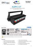
Z3 Technology User’s Manual Dual Channel HD H.264 Encoder Model Name: Z3-MVE-20 Version 1.0.4 November 2, 2011 Before attempting to connect or operate this product, please read these instructions carefully and save the manual for future use. Z3 Technology Tel: +1.402.323.0702 www.z3technology.com [email protected] Page 1 Revision History Version Date Change Note Author 1.2.2 1.2.6 1.3.1 1.0.4 8/29/11 9/1/11 11/2/11 2/13/12 Original System Firmware Upgrade Firmware Upgrade, Edited Images Associated version number with software release version. Added Troubleshooting section CH CH CH CH Page 2 TABLE OF CONTENTS PAGE # 1.0 GENERAL INFORMATION………………………………………………………………..….4 1.1 Preface……………………………………………………………………………….......4 1.2 About the Manual………………………………………………………………………..4 2.0 PARTS LIST…………………………………………………………………………………….5 2.1 Included Parts……………………………………………………………………………5 2.2 Optional Accessories……………………………………………………………………5 3.0 4.0 FEATURES……………………………………………………………………………………..6 OPERATING CONTROLS…………………………………………………………………….7 4.1 Front View………………………………………………………………………………..7 4.2 Rear View………………………………………………………………………………..7 5.0 SYSTEM CONNECTIONS…………………………………………………………………….8 5.1 PC Setup………………………………………………………………………………....8 5.2 Web Server - Encoder………………….………………………………………………9 5.3 IP Settings – Encoder…………………………………………………………………10 5.4 Encoder Configuration Options…..…………………………………………………..11 5.5 Web Server – Decoder………..………………………………………………………12 5.6 IP Settings – Decoder…………………………………………………………………12 5.7 Decoder Configuration Options………………………………………………………13 6.0 STREAMING OPERATION………………………………………………………………….14 6.1 Transport Stream (TS)………………………………………………………………...14 6.2 Real-Time Transport Protocol (RTP)……………………………...........................14 7.0 APPENDIX A: SERIAL CONTROL…………………………………………………………15 7.1 Terminal Output…….………………………………………………………………….15 7.2 System Menu Control…………………………………………………………………16 Page 3 1.0 GENERAL INFORMATION 1.1 Preface The Z3-MVE-20 is a 1 RU rack-mount system capable of processing two channels, multi-format HD video and integrated system peripherals. This system supports H.264 High Profile encode up to 1080p at 30 frames per second. The Z3-MVE-20 can be configured as a single-channel or dualchannel encoder, where the latter offers the advantage of low power consumption and lower cost per channel, compared to a PC system. The Z3-MVE-20 is a cost-effective system suitable for broadcast, video security, satellite uplink, remote monitoring and industrial applications. The Z3-MVE-20 features multiple I/O interfaces, such as HD-SDI, HDMI, composite, component, ASI and Ethernet. Multiple interfaces allow customers to quickly integrate full H.264 1080p30 performance into their network without the power consumption and physical space required of a PC-based platform. 1.2 About the Manual Before attempting to connect or operate this product, please read these instructions carefully and save this manual for future use. Page 4 2.0 PARTS LIST 2.1 Included Parts 2.2 Optional Accessories Page 5 3.0 FEATURES The Z3-MVE-20 is a dual channel, high definition, low cost, network-enabled media encoder with the following features: Two identical and completely independent HD encoders Each independent HD encoder supports: Resolutions up to 1920x1080, including 1080i, 1080p30 and 720p60 H.264, MPEG-4, MPEG-2 video Video and audio decoding Standard Definition encoding for ISDB-T, DVB-H, and other standards Video Inputs: SD/HD-SDI, HDMI/DVI, Component, Composite, VGA (Optional ASI input) Video input resizer support 1/2, 2/3 and 3/4 of standard resolutions Output Interfaces: Ethernet, ASI Outputs RTP or MPEG-2 Transport Stream USB interface for mass storage devices or other peripherals SD Card interface for local storage and firmware updates RS232 serial port for configuration and control Web-based configuration software Page 6 4.0 OPERATING CONTROLS 4.1 Front View 4.2 Rear View Page 7 5.0 SYSTEM CONNECTIONS The System can be controlled via the web server on the Z3-MVE-20. It can also be controlled via the serial port. 5.1 PC Setup Initially, the simplest way to setup the networked PC to communicate with the Z3-MVE-20 is to put the PC on the same subnet as the Z3-MVE-20. The IP address of the Z3-MVE-20 can be found by looking at the bottom side of the Z3-MVE-20. The Windows PC can be setup on the same subnet by using these parameters: Note: The static IP of the computer cannot be the same as the static IP of the Z3-MVE-20 Page 8 Microsoft Windows users 1. Go to the Start Menu and select Control Panel 2. Click on Network and Sharing Center 3. Click on View Status 4. Click on Properties. 5. Click Internet Protocol (TCP/IP) and click Properties. 6. In the Internet Protocol (TCP/IP) Properties window, select "Use the following IP address" if not already selected and specify the IP address you wish to use. While entering this data you'll also need to specify the subnet mask and default gateway. Linux users The below information is for how to specify and adjust your network settings through the command prompt. Changing your network settings will require root access. 1. Get to the command prompt. 2. Move to the /etc/sysconfig/network directory. 3. Edit the interfaces file and adjust your network settings in this file. 5.2 Web Server - Encoder Note: If you use unicast on the encoder, you must also use unicast on the VLC receiver. If you use multicast on the encoder, you must also use multicast on the VLC receiver. 1. 2. 3. 4. 5. 6. 7. 8. 9. Power on the Z3-MVE-20 Wait one minute or until LED #1 on the unit lights up Connect the Ethernet cable from the Z3-MVE-20 unit directly to the PC Disable all wireless and local area connections For a client PC to access the Z3-MVE-20 factory default settings, set the IP address of the PC to 192.168.x.XX Open Firefox or Internet Explorer 8 (or above) as your web browser Type the IP address of the Z3-MVE-20 in your web browser (http://192.168.XX.XX) and the Z3-MVE-20 Encoder web configuration menu will appear Configure the Z3-MVE-20 with your desired settings (See 5.3 Encoder Configuration Options) Press “Start Encoder” on the Encoder Control menu Page 9 5.3 IP Settings - Encoder 1. 2. 3. 4. 5. Press “Stop Encoder” on the Encoder Control menu Once the encoder has stopped, type in your desired IP settings Hit “Save User” to save your desired settings Power cycle the Z3-MVE-20 The new IP settings will now take effect Page 10 5.4 Encoder Configuration Options Encoder Setup Video Source SDI, HDMI, Component, Composite Audio Source Analog Jacks, Channels 1+2, Channels 3+4, Channels 5+6, Channels 7+8 Audio Codec AAC-LC ADTS, AAC-LC LATM, AAC-HE ADTS, AAC-HE-LATM, PCM, MP3, AC-3 Passthru, None Video Resolution Follow Input, 1080i (1920x1080), 3/4 1080i (1440x1080), XGA (1280x1024), 720p (1280x720), 4/5 720p (1024x720), D1 NTSC (720x480), D1 PAL (720x576), 4-CIF (704x576), VGA (640x480) 2-CIF (352x576), CIF (352x288), SIF (352x240), QVGA (320x240), WQVGA (320x180) Rate Control CBR, VBR, Storage, Fixed Frame Video Bit Rate Custom Video Profile Baseline, Main, High, Fast Gop Size 15 Frames, 30 Frames, 60 Frames, 120 Frames, 240 Frames Video Burst Size 150ms, 200ms, 300ms, 400ms, 500ms, 1000ms, 1200ms, 1400ms, 1600ms, 1800ms, 2000ms Video Codec H.264, MPEG-2 Frame Decimation 1/2, 1/3, 1/4 Output Setup Output Interface Ethernet, ASI, ASI+Ethernet Output Format RTP, MPEG-2 TS Dest IP Address 192.168.X.XX Dest Port 8888 PID Audio, Video, PCR Custom Local IP Setup Local IP Address 192.168.X.XX Page 11 Local Netmask 255.255.0.0 Default Gateway 192.168.0.1 5.5 Web Server – Decoder 1. Stop the Encoder by pressing “Stop Encoder” on the web server. 2. Select the “Decoder” option in the “Operating Mode” section to change the operating mode to Decoder. The title in the top-right of the browser should now say “MVE-20 Decoder” as pictured here in the example. 5.6 IP Settings - Decoder 1. 2. 3. 4. 5. Press “Stop Decoder” on the Decoder Control menu Once the decoder has stopped, type in your desired IP settings Hit “Save User” to save your desired settings Power cycle the Z3-MVE-20 The new IP settings will now take effect Page 12 5.7 Decoder Configuration Options Input Selection Input Interface Ethernet, DVB-ASI Input Format RTP, MPEG-2 TS RTP IP: Port Custom Decoder Setup Video Codec H.264, MPEG-4, MPEG-2 Audio Codec AAC, MPEG, PCM, None MVE Flag Check or Un-check Output Setup Output Interface SDI, Component, Composite Video Format Follow Input, 1080i (1920x1080), 720p (1280x720), Standard Def Video Frame Rate 50Hz, 60Hz Local IP Setup Local IP Address 192.168.X.XX Local Netmask 255.255.0.0 Default Gateway 192.168.0.XX Page 13 6.0 STREAMING OPERATION After connecting your video/audio source and configuring the Z3-MVE-20 Encoder, hit “Start Encoder” so the status below says “Status: Running.” If you are using the serial command instead, type “S” to start streaming. The way to set up VLC as your streaming receiver on your PC differs depending on the format of your output stream. If your output format is transport stream, please follow the steps below: 6.1 Transport Stream 1. Open VLC Media Player 2. On the Media menu choose “Open Network Stream” (Cntrl + N) 3. If using VLC version 1.0.X: a. On the Protocol menu choose “UDP” b. Type in the static IP address of your personal PC c. Change the Port Address to “8888” 4. If using VLC version 1.1.X: a. Enter the network URL as follows: udp://@xxx.xxx.xxx.xxx:8888 (where xxx.xxx.xxx.xxx is the IP Address of your personal PC) 5. Press play 6. If the original video is interlaced, the video can be deinterlaced as follows: a. On the Video Menu, choose “Deinterlace” and choose an option other than “Disable” If your output format is real-time transport protocol, please follow the steps below: 6.2 Real-Time Transport Protocol 1. Open VLC Media Player 2. On the Media menu choose “Open File” (Cntrl + O) 3. Under the Media Files category, choose “All Files (*)” 4. Choose the SDP file provided by Z3 Technology 5. If the original video is interlaced, the video can be deinterlaced as follows: a. On the Video Menu, choose “Deinterlace” and choose an option other than “Disable” Page 14 7.0 7.1 APPENDIX A: SERIAL CONTROL Plug-in DB-9 serial cable from Z3-MVE-20 to PC Setup Teraterm on PC for 115k, 8, N, 1, N, 1ms/char, 50ms/line Connect to proper COM port Connect the Power of Z3-MVE-20 Power-on Z3-MVE-20 Output should come immediately to Teraterm console Terminal Output Page 15 7.2 System Menu Control Streaming Encoder System Menu Control 8.0 I - Video Input Options Component_A, Composite, HDMI, HD-SDI, A - Audio Encoder Options AAC, PCM, None N - Network Address Multicast or Unicast Address T - Transport RTP, TS F - Frame Rate Divider 1, 2, 3, 4, 5 R - Resolution Follow Input, Custom, 720p, 1080i, D1 NTSC, D1 PAL, 4-CIF, 2-CIF, CIF, QCIF G - Gop Size 15 Frames, 30 Frames, 60 Frames, 120 Frames, 240 Frames B - Bitrate Custom, 50k, 64k, 128k, 250k, 500k, 750k, 1500k, 2000k, 2500k, 3000k, 3500k, 4000k, 12000k P - H.264 Profile Baseline, Main, High, Fast Y - H.264 QP Range H.264 QP range format: <min>, <init>, <max>, <minIntra>, <maxIntra> Example: 5, 28, 48, 0, 40 means: -Inter-frame QP ranges from 5 to 48 -Initial QP of 28 -Intra-frame QP ranges from 0 to 40 *Minimum allowed is 0, maximum is 51 C - Rate Control Mode CBR, VBR, Storage E - Scan Mode Interlaced, Progressive D - Delay Limit 150ms, 300ms, 500ms, 1000ms, 2000ms DYNAMIC BIT-RATE & FRAME-RATE CHANGE The dynamic bit-rate and frame-rate control will take effect, if you change *only* the following parameters: Video Bit Rate Frame Decimation After the Video Bit Rate and Frame Decimation rate have been configured to your preferred settings, hit the "Start Encoder" or "Restart Encoder" button. Page 16 The web page will respond with: Status: Changed rate The video stream will continue uninterrupted with the new parameter. 9.0 UPDATING FIRMWARE 9.1 WEB PAGE - 9.2 Locate the UPD-z3-mve02-v1.04.00.img file on your Z3 Server user account Save the file on your PC where it can easily be found Follow steps 1 through 7 in section Error! Reference source not found. On the web menu, next to “Firmware Version 1.0.4”, hit the Update button Hit Browse to find the saved .img file on your PC Hit Upload & Update Power off unit Power cycle system for clean boot and system should be updated. SD CARD - Locate the UPD-z3-mve02-v1.04.00.img file on your Z3 Server user account Place SD card into computer Open the zwriter.exe windows program (provided by Z3) Select the UPD-z3-mve02-v1.04.00.img file Select correct location for your SD card Do NOT make mistake on this item. This will cause wherever you are writing to be overwritten. There is no recovery once you hit “Write Device” Eject SD card from computer Place in SD card socket of APP board Power on system with terminal output connected to PC You will see the system updating the flash Once complete, the system will boot. Power off unit Remove SD card Power cycle system for clean boot and system should be updated. 10.0 TROUBLESHOOTING No video is usually caused by networking issues. o First: check IP address and Netmask. Ping PC from Z3-MVE-02 and ping Z3-MVE-02 from PC. Use direct connection from Z3-MVE-02 to PC without router/customer network. Once video connection is established, then add in customer specific network equipment. o Second: check to make sure firewalls are turned off o Third: check video source. Verify video source is outputting compatible analog video o Fourth: verify PC is fast enough and has enough DDR to decode compressed video o Fifth: verify VLC version is 1.1x or later Page 17 No SDP file o Check your Z3 server account Page 18