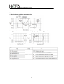
1
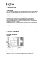
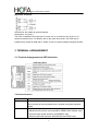
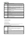
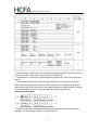
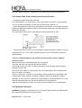
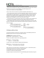
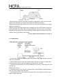
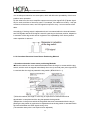
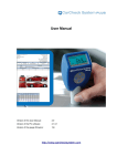
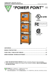
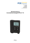
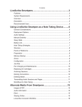
HCFA CORPORATION LIMITED
USER’S MANUAL
TX2N-1PG PULSE GENERATOR UNIT
1. INTRODUCTION ............................................................................................................. 3
1.1 Introduction ............................................................................................................. 3
2. OUTSIDE DIMENSIONS ................................................................................................. 3
2.1 Outside Dimensions ............................................................................................... 3
3. TERMINAL ARRANGEMENT ......................................................................................... 4
3.1 Terminal Arrangement and LED Indication ............................................................ 4
4. SPECIFICATIONS ........................................................................................................... 5
4.1 Specifications.......................................................................................................... 5
5. BFM LIST ........................................................................................................................ 7
5.1 BFM List ................................................................................................................. 7
5.2 System of Units and Parameter Setting ................................................................. 9
5.3 Speed Data and Position Data ............................................................................. 12
5.4 Position Data, Home Position and Current Position ............................................ 15
5.5 Operation Command ............................................................................................ 15
5.6 Status and Error Codes ........................................................................................ 18
6. OUTLINE OF OPERATION MODES ............................................................................ 21
6.1 JOG Operation and Machine Home Position Return Operation .......................... 21
6.1.1 DOG Switch................................................................................................ 22
6.1.2 Overshoot Detection Home Return Positioning Method............................ 23
6.1.3 Undershoot Detection Home Return Positioning Method.......................... 24
6.1.4 Home Position Return Operation ............................................................... 25
6.2 Single-Speed Positioning Operation and Interrupt Single-Speed Positioning
Operation .................................................................................................................... 26
6.3 Two-Speed Positioning Operation and External Command Positioning Operation
.................................................................................................................................... 27
6.4 Variable Speed Operation .................................................................................... 28
6.5 Common Matter for Operation Modes.................................................................. 29
6.6 Connection of DOG and STOP Inputs and Handling of Limit Switches for Limit
Detection..................................................................................................................... 30
6.7 Various Operation Modes and Buffer Memory Setting ........................................ 32
7. OUTLINE OF FROM/TO INSTRUCTION (PC) ............................................................. 33
8. I/O SPECIFICATIONS ................................................................................................... 33
8.1 I/O Specifications.................................................................................................. 33
9. EXTERNAL CONNECTION EXAMPLES ..................................................................... 34
9.1 Example of Connection Between TX2N-1PG and Stepper Motor ....................... 34
9.2 Example of Connection Between TX2N-1PG and Stepper Motor ....................... 34
1
HCFA CORPORATION LIMITED
9.3 Example of External Connection (MR-C Servo Amplifier..................................... 35
9.4 Example of External Connection (MR-J Servo Amplifier) .................................... 36
9.5 Example of External Connection (MR-J2(S) Servo Amplifier) ............................. 37
9.6 Example of External Connection (MR-H Servo Amplifier) ................................... 38
9.7 Example of External Connection (MR-J3 Servo Amplifier) .................................. 39
9.8 Example of External Connection (MR-JN Servo Amplifier) ................................. 40
9.9 Example of External Connection (MR-J4 Servo Amplifier) .................................. 41
10. PROGRAM EXAMPLES ............................................................................................. 42
10.1 The reciprocation by single-speed positioning ................................................... 42
11. DIAGNOSTICS ............................................................................................................ 46
11.1 Preliminary Checks and Error Indication ............................................................ 46
2
HCFA CORPORATION LIMITED
1. INTRODUCTION
1.1 Introduction
• The TX2N-1PG pulse generator unit (hereinafter referred to as “PGU”) performs simple
positioning of an independent axis (not interpolation control between multiple axes) by
supplying a prescribed quantity of pulses (100kHz maximum) to drive amplifiers for servo
or stepper motors.
• Each PGU functions as a special block which transfers data with the PC using the
FROM/TO instructions, and occupies 8 points of inputs or outputs. For the number of
connectable PGU to the PLC, refer to the manual of the PLC to be connected.
• The PGU provides connection terminals for positioning operations that require
high-velocity responses as well as those used for pulse train outputs. Other general I/O
operations are controlled via the PLC.
• Because all the program for positioning control are executed in the PC, the PGU does
not require dedicated teaching panel, etc. As the programming tools for the PLC, the
following devices are available without modification.
• GOT, Data access units can be connected to the PLC to set or display the positioning
data.
2. OUTSIDE DIMENSIONS
2.1 Outside Dimensions
TX2N-1PG
Mass (Weight): Approx. 0.2 kg (0.44 lbs)
Terminal screw: M3
Terminal screw tightening torque:0.5 to 0.8 N•m
Terminal screws must be secured to prevent a loose connection thus avoiding a
malfunction. Failure to do so may cause equipment failures or malfunctions.
3
HCFA CORPORATION LIMITED
Applicable terminals:
Accessories: No. labels for special modules
Dimensions : mm (inch)
The PGU is installed to the right side of a main unit or an extension unit of PLC or of
another extension block. For details, refer to the main unit manual. The PGU can be
installed using a DIN rail (DIN 46277, Width: 35 mm) or directly installed using M4 screws.
3. TERMINAL ARRANGEMENT
3.1 Terminal Arrangement and LED Indication
<LED allocation>
<Terminal allocation>
TX2N-1PG
Function
STOP
DECELERATION STOP input.
Can function as stop command input in external command operation
mode.
DOG
Offers following different functions depending on operation mode.
•Machine home position return operation: NEAR POINT SIGNAL input
•Interrupt single-speed operation: INTERRUPT input
•External command operation: DECELERATION START input
4
HCFA CORPORATION LIMITED
S/S
24V DC power terminal for STOP input and DOG input
Connected to sensor power supply of PC or external power supply
PG0+
Power terminal for zero point signal
Connected to servo amplifier or external power supply (5 to 24V DC, 20
mA or less)
PG0-
Enters zero point signal from drive unit or servo amplifier.
Response pulse width: 4µs or more
VIN
Power terminal for pulse output (supplied from servo amplifier or
external unit)
5 to 24V DC, 35 mA or less
FP
Terminal which outputs forward pulse or pulses. 100 kHz, 20 mA or less
(5 to 24VDC
COM0
Common terminal for pulse output
RP
Terminal which outputs reverse pulse or direction. 100 kHz, 20 mA or
less (5 to 24V DC)
COM1
Common terminal for CLR output
CLR
Output for clearing deviation counter. 5 to 24V DC, 20 mA or less Output
pulse width: 20 ms(Output when return to home position is completed or
LIMIT SWITCH input is given)
●
Spare terminal. Shall not be used a relay terminal.
4. SPECIFICATIONS
4.1 Specifications
<General specifications>
The general specifications are equivalent to those of the main unit of the PC. (For the
details, refer to the handy manual packed together with the main unit.
< Performance specifications>
Item
Specifications
Drive power
supply
1. +24V (for input signals) : 24V DC ±10% Current consumption: 40 mA
or less
Supplied from external power supply or 24+ output of PC.
2. +5V (for internal control) : 5V DC, 55 mA Supplied from PC via
extension cable.
3. For pulse output : 5V to 24V DC current consumption: 35mA or less
Number of I/O
points occupied
8 input or output points of PC for each PGU
Number of
control axes
1 (A single PC can control independent 8 axes maximum.)
5
HCFA CORPORATION LIMITED
Command
speed
●Operations are enabled at pulse speed of 10 Hz to 100 kHz.
●Command unit can be selected among Hz. cm/min, 10 deg/min and
inch/min.
Setting pulse
●0 to ±999.999
●Absolute position specification or relative travel specification can be
selected.
●Command unit can be selected among pulse, µm, mdeg and 10-4
inch.
●Multiplication of 100, 101, 102or 103can be set for position data
Pulse output
format
Forward (FP) and reverse (RP) pulse or pulse (PLS) with direction
(DIR) can be selected.
Open collector and transistor output. 5 to24V DC, 20 mA or less
External I/O
●Photocoupler insulation and LED operation indication are offered for
every point.
●3 input points: (STOP/DOG) 24V DC, 7 mA and (PG0*1) 24V DC, 20
mA(For details, refer to Section 8.1.)
●3 output points (FP/RP/CLR): 5 to 24V DC, 20 mA or less (For details,
refer to Section 8.1.)
Communication
with PC
16-bit RAM (without battery backup) buffer memories (BFMs) #0 to #31
are built in PGU.
Data communication with PC is performed using FROM/TO
instructions, etc. (For details, refer to
Section 7.1)
32-bit data is processed by combining two BFMs. (For details, refer to
Section 5.1.)
*1 One zero point signal PG0 is entered by flowing the current from the PG0+ terminal to
the PG0- terminal.
6
HCFA CORPORATION LIMITED
5. BFM LIST
5.1 BFM List
*1 Unit is µm/R, mdeg/R or 10-4inch/R.
*2 Unit is PLS, µm/R, mdeg/R or 10-4inch depending on the system of units set in the
BFM #3 b1 and b0.
*3 Only one bit among the BFM #25 b6 to b4 and b12 to b8 can be turned on. If two or
more bits among them are turned on, no operation is performed.
*4 When data is written into the BFMs #0, #1, #2, #3, #4, #5, #6 and #15, data is
calculated inside the PGU during the first positioning operation. To save this processing
time (500 ms maximum)
7
HCFA CORPORATION LIMITED
• When the power of the PGU is turned off, the BFM data is cleared. When the power of
the PGU is turned on the initial values are entered to the BFMs.
• The BFMs #0, #1 and #2 are neglected when the BFM #3 (b1, b0) is set to the motor
system.
• The instruction data format (TO/FROM, DTO/DFROM, etc.) must match the target
BFM's data format. When the instruction data format does not match the target BFM's
data format(16-bit/32-bit), the PGU will not read/write data to the BFM properly, whereas
no error will appear. This may cause an operation error to the positioning.
<Reading of 32-bit data>
• At BFM #19 and #20, variable speed operation and external command positioning
operation, can set a negative value. (-10 to-100,000 Hz)
8
HCFA CORPORATION LIMITED
5.2 System of Units and Parameter Setting
[ BFM #0 ] Pulse rate
This is the number of input pulses required by the amplifier to rotate the motor by 1
revolution. It is not the number of encoder pulses per revolution of the motor. (The pulse
rate becomes a different value in accordance with the electronic gear ratio.)
The BFM#0 is not required to be set when the motor system of units described later is
selected.
[ BFMs#2 and #1 ] Feed rate
B1 (distance specification) = 1 to 999,999µm/R
B2 (angle specification) = 1 to 999,999 mdeg/R
B3 (distance specification) = 1 to 999,999 x10-4inch/R
This is the machine travel B while the motor rotates by 1 revolution. Set either one among
B1, B2 and B3 in accordance with the unit among µm/R, mdeg/R and10-4inch/R suitable
to the application.
The BFMs #2 and #1 are not required to be set when the motor system of units described
later is selected.
The table below shows the units for position and speed in accordance with the setting of
the BFMs #2 and #1(federate)
[BFM #3 ] Parameters(b0 to b15)
Set bits 0 to 15 as follows
⑴ System of units (b1, b0)
The table below shows the units for position and speed in accordance with the setting of
the BFMs #2 and #1(federate).
9
HCFA CORPORATION LIMITED
⑵ Multiplication of position data (b5, b4)
The position data HP, P(I), P(II) and CP will be multiplied
by the value shown in the table on the left.
Example: When the value of the set position P(I) (BFMs #18 and #17) is 123 and the BFM
#3 (b5, b4) is (1, 1), the actual position (or travel) becomes as follows:
⑶ Pulse output format (b8)
The pulse output terminals FP and RP of the PGU Change as follows in accordance with
the setting (0 or 1) of b8.
•When b8 = 0: Forward pulse (FP) and reverse pulse(RP)
•When b8 = 1: Pulse (PLS) with direction (DIR)
⑷ Rotation direction (b9)
•When b9 = 0: The current position (CP) value increases with a forward pulse (FP).
•When b9 = 1: The current position (CP) value decreases with a forward pulse (FP).
This bit is used for the initial setting. The rotation direction is not required to be changed in
every actual operation.
⑸ Home position return direction (b10)
10
HCFA CORPORATION LIMITED
•When b10 = 0: The current position (CP) value decreases during return to the home
position.
•When b10 = 1: The current position (CP) value increases during return to the home
position
⑹ DOG input polarity (b12)
•When b12 = 0: The DOG (near point signal) input is turned on when the work piece is
coming near the home position.
•When b12 = 1: The DOG (near point signal) input is turned off when the work piece is
coming near the home position
⑺ Count start point (b13)
See Sections 6.1.1 to 6.1.3.
This bit specifies the point at which counting of zero point signals is started.
• When b13 = 0:Counting of zero point signals is started when the DOG input is given
(when DOG input is turned on if b12 is set to 0 or when DOG input is turned off if b12 is
set to 1).
• When b13 =1: Counting of zero point signals is started when the DOG input is given
once, then stopped.
⑻ TOP input polarity (b14)
• When b14 = 0:The operation is stopped when the input is turned on (OFF during
operation).
• When b14 = 1:The operation is stopped when the input is turned off (ON during
operation).
This polarity changeover is valid exclusively for the STOP input in the PGU.
⑼ STOP input mode (b15)
• When b15 = 0:The operation is interrupted when the stop command is given (from the
PGU or the PC) during operation, then the operation for the remaining distance is
restarted when the restart command is given.
The Jog drive begins again when the stop command is turned off from turning on when
the Jog command has been turned on.
* However, if any BFMs (except #25) is rewritten while operation is interrupted by the stop
command, the operation for the remaining distance will not be performed. Write the BFMs
(except #25) by pulse operation. When the STOP input mode takes up the remainder of
the drive operation, please set the maximum speed and operating speed as the same
value.
• When b15 = 1:The operation for the remaining distance is not performed, but the next
positioning is performed.
The Jog drive begins again when the stop command is turned off from turning on when
the Jog command has been turned on.
< Note> BFM #3
11
HCFA CORPORATION LIMITED
Write hexadecimal H□□□□in BFM # 3 in accordance with the 0 and 1 status of each bit.
Set b2, b3, b6, b7 and b11 to 0.
5.3 Speed Data and Position Data
[ BFMs#5 and #4 ] Maximum speed Vmax
Motor system and combined system: 10 to 100,000 Hz
Machine system: 1 to 153,000
This is the maximum speed. Make sure that the bias speed (BFM #6), the JOG speed
(BFMs #7 and #8), the home position return speed (BFMs #9 and #10), the creep speed
(BFM #11), the operating speed (I) (BFMs
#19 and #20) and the operating speed (II) (BFMs #23 and #24) are set respectively to a
value equivalent to or less than the maximum speed.
The degree of acceleration/deceleration is determined by this maximum speed, the bias
speed (BFM #6) and the acceleration/deceleration time (BFM #15).
[ BFM #6 ] Bias speed Vbia
Motor system and combined system: 0 to 10,000 Hz
Machine system: 0 to 15,300
This is the bias speed at time of start
When the TX2N-1PG and the stepper motor are used together, set a value while taking
the resonance area and the self-start frequency of the stepper motor into account.
[ BFMs#8 and #7 ] JOG speed VJOG
Motor system and combined system: 10 to 100,000 Hz
Machine system: 1 to 153,000
This is the speed for manual forward/reverse (JOG+/JOG-).
Set a value between the bias speed Vbia and the maximum speed Vmax.
[ BFMs #10 and #9 ] Home position return speed (high speed) VRT
Motor system and combined system: 10 to 100,000 Hz
Machine system: 1 to 153,000
This is the speed (high speed) for returning to the machine home position.
Set a value between the bias speed Vbia and the maximum speed Vmax.
[ BFM #11 ] Home position return speed (creep) VCR
Motor system and combined system: 10 to 10,000 Hz
Machine system: 1 to 15,300
This is the speed (extremely slow speed) after the near point signal (DOG) for returning to
the machine home position.
It is the speed immediately before stopping in the machine home position. It is
recommended to set it as slow as possible so that the precision of the home position
becomes better.
[ BFM #12 ] Number of zero point signals for home position return N
0 to 32,767 PLS
This is the number of zero point signals counted for returning to the machine home
position.
12
HCFA CORPORATION LIMITED
When the zero point signal is not used and the machine should be stopped immediately
by only the DOG input, set the BFM #12 to 0. However, pay rigid attention so that the
machine is not damaged when it is immediately stopped from high-speed operation.
[ BFMs#14 and #13 ] Home position HP
Motor system: 0 to±999,999 PLS
Machine system and combined system: 0 to±999,999
This is the home position used for returning to the Machine home position.
When the home position return operation is completed, the value set here is written to the
current position (BFMs #26 and #27).
[ BFM #15 ] Acceleration/deceleration time Ta
50 to 5,000 ms
This is the time between the bias speed (BFM #6) and
The maximum speed (BFMs #5 and #4).
The degree of acceleration/deceleration is determined by the maximum speed, the bias
speed and the acceleration/deceleration time.
[ BFMs#18 and #17 ] Set position (I) P(I)
Motor system: 0 to±999,999 PLS
Machine system and combined system: 0to±999,999
This is the target position or the travel distance for operation.
When the absolute position is used, the rotation direction is determined in accordance
with the absolute value of the set position based on the current position (BFMs #26 and
#27).
When the relative position is used, the rotation direction is determined by the sign of the
set position.
[ BFMs#20 and #19 ] Operating speed (I) V(I)
Motor system and combined system: 10 to 100,000 Hz
Machine system: 1 to 153,000
This is the actual operating speed within the range between the bias speed Vbia and the
maximum speed Vmax.
In variable speed operation and external command positioning operation, forward rotation
or reverse rotation is performed in accordance with the sign (positive or negative) of this
set speed.
13
HCFA CORPORATION LIMITED
[ BFMs#22 and #21 ] Set position (II) P(II)
Motor system: 0 to±999,999 PLS
Machine system and combined system: 0to±999,999
This is the set position for the second speed in two-speed positioning operation.
[ BFMs #24 and #23 ] Operating speed (II) V(II)
Motor system and combined system:
10 to 100,000 Hz
Machine system: 1 to 153,000
This is the second operating speed in two-speed positioning operation within the range
between the bias speed Vbia and the maximum speed Vmax.
[ BFMs #27 and #26 ] Current position CP
Motor system:-2,147,483,648 to +2,147,483,647 PLS
Machine system and combined system: - 2,147,483,648 to +2,147,483,647
The current position data is automatically written here.
When the value set here is read by the PC for monitoring, make sure to read it in the unit
of 32 bits.
< Conversion of system of units>
The following relationship is present between the motor system of units and the machine
system of units. They are automatically converted each other.
A indicates the pulse rate. B1 to B3 indicate the feed rate PPS indicates the pulses per
second.
When setting the speed data using the machine system of units, make sure that the value
converted into pulses is within the range determined for the motor system and the
combined system (Hz).
< Stepwise speed command value>
The frequency f of the pulse generated in the PGU is stepwise as follows
Where, n: Integer in range of 40 to 400,000
For example, in the case of n = 40, f = 100,000 Hz in the case of n = 41, f = 97,560 Hz
14
HCFA CORPORATION LIMITED
Any pulse whose frequency is between the two values above cannot be generated.
5.4 Position Data, Home Position and Current Position
• The position data includes the following:
HP: Home position, P(I): Set position (I), P(II): Set position (II) and CP: Current position
The unit and the multiplication of each item are described in Section 5.2.
• When the operation of returning to the machine home position is completed, the home
position HP (BFMs #14 and #13) value is automatically written to the current position CP
(BFMs #27 and #26).
The figure below shows the CP value when the home position HP is -100.
• The set positions P(I) and P(II) can be treated as absolute positions (distance from the
current position CP = 0) or relative positions (travel from the current stop position) as
described later.
< Error in command between the machine system of units and the combined
system of units>
When the pulse rate of the BFM #0 (#2, #1) is supposed
The pulse rate as A, the feed rate as B and the relative
travel distance as C, the value “C×(A/B)” indicates the pulse quantity which should be
generated by the PGU.
Even if the value “(A/B)” is not an integer, error is not generated in the command if the
value “C×(A/B)” is an integer.
However, if the value “C×(A/B)” is not an integer, accumulated error is generated in the
current position when relative movement is repeated. When the absolute is used for
operation, an error less than 1 pulse may be generated by counting fractions over 1/2 as
one and disregarding the rest, but accumulated error is not generated.
When the motor system of units is used, such an accumulated error is not generated.
5.5 Operation Command
[ BFM #25 ] Operation command (b0 to b11, b12) After data is written to the BFMs #0 to
#24, write the BFM #25 (b0 to b12) as follows.
[b0] When b0 = 1: Error reset
15
HCFA CORPORATION LIMITED
The error flag (BFM #28 b7) described later is reset. When the error occurs, the
positioning completion signal (BFM #28 b8) is reset.
[b1] When b1 = 0→1: Stop
This bit functions in the same way with the
STOP input in the PGU, but the stop operation can be performed from the sequence
program in the PC.
However, if this bit is changed from 0 to 1 before the STOP input is given in the PGU in the
external command positioning mode, the machine is decelerated and stopped
[b2] When b2 = 1: Forward pulse stop
The forward pulse is immediate stopped in the forward limit position.
[b3] When b3 = 1: Reverse pulse stop
The reverse pulse is immediate stopped in the reverse limit position.
[b4] When b4 = 1: JOG+ operation
When b4 continues to be 1 for less than 300 ms, one forward pulse is generated.
When b4 continues to be 1 for 300 ms or more, continuous forward pulses are generated.
[b5] When b5 = 1: JOG- operation
When b5 continues to be 1 for less than 300 ms, one reverse pulse is generated.
When b5 continues to be 1 for 300 ms or more, continuous reverse pulses are generated.
[b6] When b6 = 0→1: Home position return start
The machine starts to return to the home position, and is stopped at the machine home
position when the DOG input (near point signal) or thePG0 (zero point signal) is given.
[b7] When b7 = 0: Absolute position
When b7 = 1: Relative position
The relative or absolute position is specified in accordance with theb7 status (1 or 0).
(This bit is valid while operation is performed using b8, b9 or b10.)
[b8] When b8 = 0→1: Single-speed positioning operation start
Single-speed positioning operation is performed.
For the details, see Section 6.2.
[b9] When b9 = 0→1: Interrupt single-speed positioning operation start
Interrupt single-speed positioning operation is performed. For the details, see Section 6.2.
[b10] When b10 = 0→1: Two-speed positioning operation start
Two-speed positioning operation is performed. For the details, see Section 6.3.5.
16
HCFA CORPORATION LIMITED
[b11] When b11 = 0→1: External command positioning operation start
External command positioning operation is performed. The rotation direction is
determined by the sign of the speed command.
For the details, see Section 6.3.
[b12] When b12 = 1: Variable speed operation Variable speed operation is performed.
For the details, see Section 6.4.>
• Error can be reset by forcedly turning on/off the peripheral unit. The input X000 does not
have to be used.
When the data on absence/presence of error and the error code should be saved even
after power interrupt, use the auxiliary relays or data registers backed up by the battery.
• The stop command is generally provided in the PGU, and is also output from the
sequence program in the PC. In such a case, the input X001 is not required.
• In operation which does not require returning to the home position such as inching
17
HCFA CORPORATION LIMITED
operation with a constant feed rate, the input X006 is not required.
• When which one between the relative and absolute positions should be used is always
determined, drive the M7 using the M8000 or set the M7 always to OFF.
• Drive one of theM8 to M12 using theM8000.
If two or more of them are turned on, operation is disabled. (See Section 6.4.)
• As the general start command, create an appropriate sequence using the input X007 to
drive the M8 to M12. (See Section 9.1.) The time after theTX2N-1PG receives the start
command until it generates a pulse is approximately 10 ms usually. However, 500 ms
maximum is required for the first operation after the PC starts running or for the first
operation after the BFM#0, #1, #2, #3, #4, #5, #6 or #15 is written.
• The TO instruction is a write instruction from the PC to the BFM. In the example on the
left, the PGU is connected as a special unit in the position nearest the main unit.
• In the program below, the start bit for the operation mode cannot be set to OFF inside
the PGU, so operation from the second time and later cannot be performed. Correct it as
shown in the right.
5.6 Status and Error Codes
The status information to notify the PC of the PGU status is automatically saved in the
BFM #28. Read it into the PC using the FROM instruction.
[ BFM #28] Status information (b0 to b8)
[b0] When b0 = 0: BUSY When b0 = 1: READY
This bit is set to BUSY while the PGU is generating pulses.
[b1] When b1 = 0: Reverse rotation
When b1 = 1: Forward rotation
This bit is set to 1 when operation is started with forward pulse.
[b2] When b2 = 0: Home position return unexecuted
When b2 = 1: Home position return completed
When returning to the home position is completed, b2 is set to 1, and continues to be 1
until the power is turned off. To reset b2, use the program.
In everyTX2N-1PG, b2 can be reset by the program. ]
Connect b2 in series to the start command
(Program example to reset b2) Write ”K0" to the BFM #28 (status information) using the
18
HCFA CORPORATION LIMITED
TO (P) instruction.
By this program, b2 (home position return completed) only in the BFM #28 is reset and
rewritten to 0.
BLK No.BFM No.Written value
Number of transfer point
[b3] When b3 = 0: STOP input OFF
When b3 = 1: STOP input ON
[b4] When b4 = 0: DOG input OFF
When b4 = 1: DOG input ON
[b5] When b5 = 0: PG0 input OFF
When b5 = 1: PG0 input ON
Any of them represents the ON/OFF status of the PGU input as it is.
[b6] When b6 = 1: Current position value overflow
The 32-bit data saved in the BFMs (#27 and #26) has overflown. This bit is reset when
returning to the home position is completed or the power is turned off.
[b7] When b7 = 1:Error flag
b7 becomes 1 when an error has occurred in the PGU, and the contents of the error are
saved in the BFM #29.
This error flag is reset when the BFM #25 b0 becomes 1 or the power is turned off.
[b8] When b8 = 0: Positioning started
When b8 = 1: Positioning completed
b8 is cleared when positioning is started home position return start, or error reset, and set
when positioning is completed. b8 is also set when returning to the home position is
completed.
• Various start commands are accepted exclusively while the BFM #28 b0 is set to 1
(READY).
• Various data is also accepted exclusively while the BFM #28 b0 is set to 1 (READY).
However, the BFM #25 b1 (stop command), the BFM #25 b2 (forward pulse stop) and the
BFM #25 b3 (reverse pulse stop) are accepted even while the BFM #28 b0 is set to 0
(BUSY).
• The data can be read from the PGU to the PC without regard to the setting of the BFM
#28 b0.
• The current position is changed accompanied by generation of pulses even while the
19
HCFA CORPORATION LIMITED
BFM #28 b0 is set to 0 (BUSY).
<Reading of status information>
* When a drive amplifier for a stepper motor without the positioning completed output is
used, this signal can be used for recognition of positioning completed and the next
operation can be started.
< Error code No. > [ BFM #29>
The following error code Nos. are saved in the BFM #29. Read and check it when the
BFM #28 b7 is set to 1 (Error present)
OO1: Large/small relationship is incorrect. (Vmax< Vbia or VRT<VCR) OO indicates the
lower word No. of the related BFM.
OO2: Setting is not performed yet. (V(I), P(I), V(II) or P(II)) However, V(II) and P(II) should
be set exclusively in two-speed operation or external command operation. OO indicates
the corresponding BFM No. For example, “172" indicates that the BFMs #18 and #17 are
set to 0.
OO3: Setting range is incorrect. OO indicates the corresponding BFM No. For example,
“043" indicates that the BFMs #5 and #4 are set to a value outside the range of 10 to
100,000 PPS.
• When a speed command specifies a value equivalent to or more than Vmax or a value
equivalent to or less than Vbia, error does not occur. Vmax or Vbia is used for operation.
20
HCFA CORPORATION LIMITED
• Though the ready status can be specified even while an error is present, the start
command is not accepted.
6. OUTLINE OF OPERATION MODES
6.1 JOG Operation and Machine Home Position Return Operation
Seven operation modes are available in the PGU in accordance with the start command
type. The data on speed and position should be transferred preliminarily from the PC to
the buffer memories (BFMs) of the PGU. The transfer data addresses are BFMs #0 to #25
which are allocated as described in Section 5.1.
■JOG operation
While the forward or reverse button is pressed and held, the motor is driven forward or in
reverse.
Any value between the bias speed Vbia(BFM #6) and the maximum speed Vmax(BFMs #5
and #4) is valid as the command speed VJOG (BFMs #8 and #7). The
acceleration/deceleration time Ta(BFM #15) is the time between Vbia and Vmax. Vmax,Vbia
and Ta are equivalent in the operation modes described later.
■Machine home position return operation
When the home position start command is received, the motor makes the machine return
to the home position.
When returning to the home position is completed, the home position HP (BFMs #14 and
#13) value is written to the current position CP (BFMs #27 and #26).
Position ➃ in the figure below indicates the machine home position.
21
HCFA CORPORATION LIMITED
➀When the home position return start command is changed from OFF to ON, the home
position return operation is started at the speed VRT (BFMs #10 and #9).
➁When the near point signal DOG input is turned on, the motor decelerates to the creep
speed VCR (BFM #11).
➂When the near point signal DOG input is changed from ON to OFF and the motor zero
point signal PG0 is received (There is setting by BFM #3 b13), the motor is immediately
stopped in the position➃.The value of the home position address is written in the home
position value by generating a clear signal.
For the details, refer to Sections 6.1.1 to 6.1.4.
6.1.1 DOG Switch
< DOG switch for returning to home position>
• A dog whose length is L is fixed to a table driven in the left and right direction by a servo
motor via a ball thread.
• When the table moves in the home position return direction, the dog is in contact with
the limit switch (LSD) for near point detection, and the LSD is actuated.
• The LSD is turned ON from OFF when the BFM #3 b12 is set to 0, and turned OFF from
ON when the
BFM #3 b12 is set to 1.
• The home position return direction is determined by the BFM #3 b9 (rotation direction)
and b10 (home position return direction).
• The limit switch LSD is often referred to as dog switch. The actuation point of the dog
switch is rather dispersed.
22
HCFA CORPORATION LIMITED
It is not always actuated at one same point, which will affect the repeatability of the home
position return operation.
On the other hand, the servo amplifier outputs one zero point signal PG0 (Z phase signal
0P) for each revolution of the servo motor. For example, if the table is moved by 1 mm per
revolution of the servo motor, one PG0 signal is output for every 1 mm movement of the
table.
Accordingly, if the dog switch is adjusted so that it is actuated within the interval between
two PG0 signals and the PG0 signal is used for returning to the home position, dispersion
in actuation of the dog switch can be neglected. The repeatability of the home position
return operation is assured.
6.1.2 Overshoot Detection Home Return Positioning Method
< Overshoot detection home return positioning Method>
●With this method, the motor starts deceleration when the dog is in contact with the dog
switch, and the motor is stopped immediately when one (or several) zero point signal PG0
is received after the dog has passed the dog switch. (BFM #3 b13 = 1).
➀With this method, the length L of the dog is required to be determined so that
deceleration is completed until the dog has passed the dog switch.
➁Dispersion in the point at which the dog switch becomes unactuated while the dog is
passing the dog switch is required to be adjusted so that the dog switch is actuated within
the interval between two PG0 signals at any time.
(The actuation start point is not required to be adjusted.)
23
HCFA CORPORATION LIMITED
➂BFM #12 determines how many zero point signals PG0 should be counted after the dog
has passed the dog switch. With this method, set the BFM #12 always to 1 so that the
motor is stopped at the first zero point signal PG0.
➃When the operation is stopped, the deviation counter clear signal CLR of the servo
amplifier is output. The home position (BFMs #14 and #13) value is transferred to the
current position (BFMs #27 and #26), and the home position return completed flag (BFM
#28 b2) is set to 1.
• It may be required to perform a home return operation after the dog has passed the dog
switch. In such a case, the dog should be preliminarily moved back to a position before
the dog switch by the jog operation before the home position return operation is performed
again. This procedure may be automatically performed when the limit switches for
detecting the forward and reverse limits are connected to the PC. (See Section 6.1.4.)
6.1.3 Undershoot Detection Home Return Positioning Method
< Undershoot detection home return positioning method >
• With this method, the motor starts deceleration when the dog is in contact with the dog
switch, and the motor is stopped immediately when the specified number of zero point
signals PG0 are received and the speed becomes sufficiently slow. (BFM #3 b13 =0)
➀With this method, the number of zero point signals is required to be set so that
deceleration is completed before the stop point.
➁Set the length L of the dog long enough so that the dog switch continues to be actuated
even when the dog is at the stop point. This allows the dog automatically go back and
reproach the dog switch before the home position return operation is performed again
consecutively.
But even if the dog is short, when the limit switches for detecting the forward and reverse
limits are connected to the PC, the dog switch can automatically go back using these limit
switches. (See Section 6.1.4.)
➂Dispersion in the point at which the dog starts to be in contact with the dog switch is
required to be adjusted so that the dog switch is actuated within the interval between two
24
HCFA CORPORATION LIMITED
PG0 signals at any time.
➃Set the home position return speed VRT as small a value as possible because there may
be a response lag with the dog switch. It is recommended to set a VCR value small enough
compared with the VRT value so that the stop precision is improved.
➄When the operation is stopped, the error counter clear signal CLR of the servo amplifier
is output. The home position (BFMs #14 and #13) value is transferred to the current
position (BFMs #27 and #26), and the home position return completed flag (BFM #28 b2)
is set to 1.
6.1.4 Home Position Return Operation
< Home position return operation>
The home position return operation varies depending on the start position.
①The near point signal is turned off (before the DOG passes).
②The near point signal is turned on.
③The near point signal is turned off (after the DOG has passed).
For this operation, the limit switches for detecting the forward limit and the reverse limit
should be provided on the PC.
When the limit switch for limit detection is actuated, the home position return operation is
not performed even if the home position return operation is started. Move the dog by
performing the JOG operation so that the limit switch for limit detection is not actuated,
then start the home position return operation.
*1 The example above shows the case where the BFM #3 b12 is set to 0 (DOG input
polarity OFF→ON).
*2 When the limit switch for limit detection is turned on, the pulse output is immediately
stopped (BFM #25 b3: ON). At this time, the clear signal is also output. Please connect the
PLC side limit switch inside the servo side limit switch.
Avoid turning the forward pulse stop (BFM #25 b2) or reverse pulse stop (BFM #25 b3) to
ON except in the forward/reverse limit position.
25
HCFA CORPORATION LIMITED
< When the stepper motor is used >
When the stepper motor is used, rigid attention should be paid to the following items.
①If the motor capacity is not sufficient compared with the load torque, the motor may stall.
In such a case, even if the specified quantity of pulses are supplied the motor, the
expected drive quantity may not be obtained.
②Start and stop the motor slowly enough (by setting a long acceleration/deceleration
time to the BFM #15) so that the acceleration/deceleration torque does not become
excessive.
③A resonance point is present in low speed operation. It is recommended to avoid this
point. Set the bias speed (BFM #6), and do not perform operation at a speed slower than
that. 4An external power supply may be required for signal communication with the drive
amplifier.
6.2 Single-Speed Positioning Operation and Interrupt Single-Speed
Positioning Operation
■Single-speed positioning operation
When the single-speed positioning operation command is received, the motor performs
the following operation.
When the start command is given, the motor accelerates up to the operating speed V(I)
(BFMs #20 and #19), then decelerates and stops in the set position P(I) (BFMs #18 and
#17).
The absolute position from the point at which the current position CP becomes 0 (electric
home position) or the relative position from the start position can be specified as the set
position. When a servo motor is used, Vbia is generally set to 0.
■Interrupt single-speed positioning operation
When the interrupt single-speed positioning operation command is received, the motor
performs the following operation.
26
HCFA CORPORATION LIMITED
The interrupt command is connected to the DOG input in the PGU.
When the start command is received, the motor starts operation. When the INTERRUPT
input is received, the motor moves by the specified distance, then stops (The relative
travel exclusively can be specified.)
The current value is cleared by the start command. The current value starts to change by
the INTERRUPT input, and becomes equivalent to the set position when the operation is
completed.
Accordingly, rigid attention should be paid when operations using absolute position
specification are performed also.
The interrupt command detects change in the input signal. (OFF→ON, ON→OFF)
6.3 Two-Speed Positioning Operation and External Command
Positioning Operation
■Two-speed positioning operation
The motor performs the following operation by the two-speed positioning operation
command. Approach at high speed as well as processing and moving forward at low
speed can be performed.
When the start command is received, the motor performs positioning at the operating
speed V(I) (BFMs #20 and #19) until the set position P(I) (BFMs #18 and #17), then at the
operating speed V(II) (BFMs #24 and #23) until the set position P(II) (BFMs #22 and #21)
(two-step speed).
■External command positioning operation
Commands for determining the deceleration start point and the stop point are given from
the external limit switches. The PGU does not control the pulse quantity, and positioning is
27
HCFA CORPORATION LIMITED
performed by the two-step speed technique.
When the start command is received, the motor performs positioning at the operating
speed V(I) (BFMs #20 and #19) until the deceleration command is received. At that time,
the motor decelerates to the operating speed V(II) (BFMs #24 and #23). When the stop
command is received, pulse generation is stopped immediately.
The rotation direction is determined by the sign (positive or negative) of the operating
speed V(I).
Please make the positive/negative setting of operation speed V(II) the same as the
positive/negative setting of operation-speed V(I). An unintended action may result if the
positive/negative setting differs.
The deceleration command detects the change in the input signal. (OFF→ON, ON→OFF)
The stop command reads the state of the input signal level. (OFF or ON).
6.4 Variable Speed Operation
■Variable speed operation
• When the operation command BFM #25 b12 is set to 1, the speed pulses specified in
the BFMs (#20 and #19) are generated.
• This operating speed can be freely changed even while pulses are generated. However,
because there is no cushion start/stop function, acceleration and deceleration must be
controlled by the PC.
• Only b0 (error reset) and b12 (variable speed operation) of the operation command
BFM #25 are valid in this mode. Set b1 to b11 to 0. When b12 is set to 1, variable speed
operation is performed.
When b12 is set to 0, pulse output is stopped. (The pulse output does not stop even if “0”
is written in BFM #20, #19.)
• As for the parameter BFM #3, only b1 and b0 (system of units) and b8 (pulse output
format) are valid.
• The rotation direction (forward or reverse) can be specified by the sign (positive or
negative) of the speed command (BFMs #20 and #19).
28
HCFA CORPORATION LIMITED
• Do according to the undermentioned procedure when you change the direction of the
rotation.
① Turn OFF b12 of BFM #25.
② Change the value at drive speed (BFM #20, BFM#19).
(The direction of the rotation is decided according to the sign)
③ Again, turn ON b12 of BFM #25
6.5 Common Matter for Operation Modes
< Handling the stop command>
In all operation modes, the stop command is valid at any time during operation. However,
if a stop command is received during a positioning operation, the motor decelerates and
stops. And after restarting, the motor normally travels by the remaining distance and then
stops. (The motor can be stopped and the operation can be completed without traveling
the remaining distance. Refer to 5.2)
< Duplicated specifications for various operation modes >
When the bits which determine operation modes such as b4 to b6 and b8 to b12 are
turned on simultaneously in the operation command BFM #25, any operation is not
executed. If another mode input is turned on while operation is being performed in any
mode, such an input is neglected.
< When travel time is small >
When the travel time is small compared to the acceleration/deceleration time (Ta), the
motor cannot realize specified speed.
●Single-speed positioning operation
●Interrupt single operation
●Two-speed positioning operation
If the travel time is shorter than the time (Ta) for the
PGU to accelerate to the operation speed Ι, the PGU
operates at the operation speed ΙΙ from the beginning.
29
HCFA CORPORATION LIMITED
The PGU decelerates before reaching P(Ι) when the
travel distance to decelerate to stop from V(Ι) is
larger than P(ΙΙ).
6.6 Connection of DOG and STOP Inputs and Handling of Limit Switches
for Limit Detection
Various limit switch inputs are connected to the DOG input and the STOP input in
accordance with the operation mode.
The polarity of these limit switch inputs is inverted by the state of the BFM #3 b12 and b14.
(Refer to 5.2) Connection examples are shown below.
➀Home position return operation mode
(BFM #25 b6 = 0→1)
➁Interrupt single-speed operation mode
(BFM #25 b9 = 0→1)
➂External command operation mode
(BFM #25 b11 = 0→1)
< When normally open contacts are used >
The input connection diagram shown below indicates the case where the BFM #3 b 12
and b14 are set to 0 and normally open contacts (a-contacts) are used.
30
HCFA CORPORATION LIMITED
Input switches SW1 to SW3 are selected in accordance with the type of operation.
< When normally closed contacts are used >
The input connection diagram shown below indicates the case where the BFM #3 b12 and
b14 are set to 1 and normally closed contacts (b-contacts) are used.
Input switches SW1 to SW3 are selected in accordance with the type of operation.
• To assure safety, provide limit switches for detecting the forward and reverse limits on
the servo amplifier also. (See Section 8.4.) Make sure so that the limit switches on the PC
are actuated simultaneously with or a little earlier than the limit switches on the servo
amplifier.*1
31
HCFA CORPORATION LIMITED
*1 When you perform the zero return operation, please be sure to connect the PLC limit
switch inside and to connect the servo side limit switch outside.
• Because a drive amplifier for a stepper motor does not have these terminals, make sure
to provide limit switches on the PC.
• When b2 and b3 of the BFM #25 are driven by these signals, pulse output is immediate
stopped and the counter clear output CLR is generated. (See Section 8.4.)
• Evade from the state of the pulse output stop by Jog in the opposite direction when
forward pulse stop (BFM #25 b2) or reverse pulse stop (BFM #25 b3) is turned on.
• Because the counter clear output CLR is generated, the forward pulse stop and the
reverse pulse stop cannot be used as a stop and home position.
•When the STOP input turns on, signals, such as the JOG +operation/JOG-operation/start
input, are null and void.
6.7 Various Operation Modes and Buffer Memory Setting
< Various operation modes and buffer memory setting >
O indicates the item required to be set.
*1 When a servo motor is used, the initial value 0 can be used. *2 Valid information
*3 FP/RP output is generated by a positive/negative speed command. The absolute value
shall be a value within the range between the bias speed (BFM #6) and the maximum
speed (BFMs #5 and #4).
32
HCFA CORPORATION LIMITED
7. OUTLINE OF FROM/TO INSTRUCTION (PC)
7.1 FROM/TO Instruction
m1 :
m2 :
Special unit/block No. (K0 to K7 starting from the one nearest the basic unit)
Head address of buffer memory (m2 = K0 to K31)
: Head address of transfer destination T, C, D, KnM, KnY, KnS, V and Z can be
specified, and element No. can be coupled with an index.
n:
Number of transfer points (K1 to K32 for 16-bit instruction, and K1 to K16 for 32-bit
instruction
m1, m2, n : Same as above
: Head address of transfer destination T, C, D, KnX, KnM, KnY, KnS, V, Z, K and H
can be specified, and element No. can be coupled with an index.
●When X010 and X011 are turned off, transfer is not performed, and data in the transfer
destination is not changed. For the details, refer to the programming manual of the PC
main unit.
8. I/O SPECIFICATIONS
8.1 I/O Specifications
33
HCFA CORPORATION LIMITED
9. EXTERNAL CONNECTION EXAMPLES
9.1 Example of Connection Between TX-1PG and Stepper Motor
*1: Connect either one in accordance with the external supply voltage. (See Section 8.1
Output Specifications.)
*2: The number of counts of zero signals is adjusted to 0 when there is no home position
sensor. At this time, when the dog input operates, the motor stops at once. Make the
home position return speed low-speed very because it does not destroy the machine.
9.2 Example of Connection Between TX2N-1PG and Stepper Motor
*1: The number of counts of zero signals is adjusted to 0 when there is no home position
sensor.
At this time, when the dog input operates, the motor stops at once. Make the home
position return speed low-speed very because it does not destroy the machine.
34
HCFA CORPORATION LIMITED
9.3 Example of External Connection (MR-C Servo Amplifier
*1 To release the alarm status, turn off the power, remove the cause of the alarm, then
turn on the power again.
*2 The failure (ALM) signal is turned on in the normal status. When an alarm has occurred
(the ALM signal is turned off), stop pulse generation from the PGU using the program in
the PC.
*3 To assure safety, it is recommended to set the LSP and LSN signals to effective
function parameters (using the parameter No. 6 in the MR-C servo amplifier).
35
HCFA CORPORATION LIMITED
*4 TX2N-1PG : Connect the VIN terminal.
9.4 Example of External Connection (MR-J Servo Amplifier)
*1 TX2N-1PG: Connect the VIN terminal.
*2 Pin No. for the case where Pr9 of the servo amplifier is set to 042
36
HCFA CORPORATION LIMITED
9.5 Example of External Connection (MR-J2(S) Servo Amplifier)
*1 TX2N-1PG: Connect the VIN terminal
*2 Pin No. can be modified using the extension parameter. (The example below shows the
case where the initial value is set.
37
HCFA CORPORATION LIMITED
9.6 Example of External Connection (MR-H Servo Amplifier)
*1 TX2N-1PG: Connect the VIN terminal
38
HCFA CORPORATION LIMITED
9.7 Example of External Connection (MR-J3 Servo Amplifier)
39
HCFA CORPORATION LIMITED
9.8 Example of External Connection (MR-JN Servo Amplifier)
40
HCFA CORPORATION LIMITED
9.9 Example of External Connection (MR-J4 Servo Amplifier)
*1 When the TX2N-1PG and MR-J4 are used together, the TX2N-1PG may send 1 extra
pulse depending on the power ON timing of both units and the timing of the servo on
signal.
*2 Set the command pulse input form of the servo amplifier (PA13) MR-J4-A to "021*"
(negative logic, command input pulse train filter: 500 kpps or less). In "*", set "0" when the
pulse output type of TX2N-1PG is "Forward/reverse pulse train", and set "1" when it is
"Pulse train + Direction".
41
HCFA CORPORATION LIMITED
10. PROGRAM EXAMPLES
10.1 The reciprocation by single-speed positioning
Do not put the load on the motor for safety when you confirm the operation according
to this program example.
<Outline of positioning>
1. The position of the motor moves to the machine home position according to the home
position return start instruction now. (Machine home position return operation)
At this time, the machine home position address is assumed to be “0”.
2. While the forward or reverse button is pressed and held, the motor is driven forward or
in reverse. (Jog operation)
3. The value of the motor advances 10000 mm according to the automatic drive start
instruction. After wards, Y000 is turned on for two seconds as a stand by display
stopping and at this time. Finally, the value of the motor retreats by 10000 mm.
(Single-speed positioning operation)
42
HCFA CORPORATION LIMITED
Drive chart
1. Machine home position return operation
2. Jog operation
3.Single-speed positioning operation
<I/O allocation>
43
HCFA CORPORATION LIMITED
<Setting of buffer memory (BFM)>
1: This example is described as an example of servo mode by Mitsubishi Electric
Corporation amplifier MR- J2. The value is different according to the connected servo
amplifier.
The servo amplifier does the following setting according to the parameter.
Control mode: Position control
Electronic gear: CMX / CDV = 1/1
Specified pulse selection: Forward reverse pulse, Negative-true logic
Set other items according to the usage.
<PC PROGRAM> Example using the FROM and TO instructions*1
44
HCFA CORPORATION LIMITED
*1 PLC can use direct specification of buffer memory.
For the details, refer to PLC Series Programming Manual - Basic & Applied instruction
Edition.
45
HCFA CORPORATION LIMITED
11. DIAGNOSTICS
11.1 Preliminary Checks and Error Indication
< To ensure correct operation >
➀Make sure that the PGU I/O wiring and the extension cable connections are correct.
Indicate clearly the special block No. on the panel face by adhering the labels offered as
accessories.
➁One PGU can occupy up to 8 points (including both inputs and outputs). Power of 5 V,
55 mA is required to be supplied from a main unit or an extension unit.
Calculate and make sure that the total current required by all of the special blocks does
not exceed the allowable current of the main unit or the extension unit used.
➂In any positioning operation, the specified data should be written preliminarily to the
BFMs #0 to #24, then the BFM #25 should give an appropriate command. Otherwise, the
PGU does not function.
Sometimes, however, data writing may not be required for some or all of the BFMs #0 to
#24 depending on the operation mode.
Generally, the BFMs #0 to #15 save the standard data, and the BFMs #17 to #24 save the
operation data. For the data to be set, see Section 6.6.
< Error indication >
46
HCFA CORPORATION LIMITED
➀LED indication
The PGU panel has the following LEDs:
Power indication : The POWER LED is lighted when 5 V power is supplied from the PC.
Input indication : When STOP, DOG or PG0 is received by the PGU, the corresponding
LED is lighted respectively.
Output indication : When FP, RP or CLR is output by the PGU, the corresponding LED is
lighted respectively.
Error indication : When an error occurs, the ERR LED flashes and the start command is
not accepted.
➁Error check
Various errors can be checked by reading the contents of the BFM #29 to the PC.
For the error descriptions, see Section 5.6.
< Note >
When performing the withstand voltage test of theTX-1PG, make sure to measure the
voltage between the entire terminals and the ground terminal.
When performing the withstand voltage test of theTX2N-1PG, make sure to use the PC
main unit also and to measure the voltage between the entire terminals of theTX2N-1PG
and the ground terminal of the PC main unit.
47