1
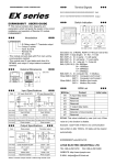
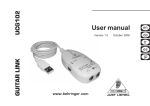
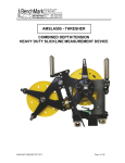
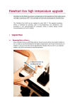
LIYAN PROGRAMMABLE LOGIC CONTROLLER
LYPLC
Ex1n1PG
USER’S MANUAL
Chapter 0
Foreword
♦ Ex1n1PG Pulse Generation Unit (called 1PG) output pulse to driver of corresponding servo motor or stepping
motor to execute control of independent one axis.
♦ Ex1n1PG is for Special extension module of LYPLC EX1n series to use FROM/TO command to do data
transmission, not occupy any PLC points. Maximum is connection of 8 units of Ex1n1PG to execute multi-axes
independent running.
♦ Programs of Ex1n1PG are made by PLC main unit, therefore there is no need to use programming panel.
FROM/TO Instruction
 FROM
FNC(78)
D
P
FROM
16 bits: FROM(P) - - - - - - - - - - - - - - - - - - - - - - - - 9 steps
32 bits: (D)FROM(P) - - - - - - - - - - - - - - - - - - - - -17 steps
Operands:
EX
EX1S
EX1N
EX2N
[D.]
K.H.
KnX
KnY KnM KnS
T
C
m1 = 0 ~ 7 no. of special module
m2.= 0 ~ 32767 no. of buffer memory (BFM)
n.= 1 ~ 31 no. of read (when D, n=1~15)
Operands:
Flag:
X00
FROM P
m1.
m2.
[D.]
n.
K1
K29
K4M0
K1
module no
D
V,Z
BFM# destination read no.
♦When X00 ON, the buffer memory of special module BFM#29 to be read out and stored into M00~M15.
<< Special Device Module Number m1>>
CPU
I/O
module no.0
I/O
X10~X17
Y10~Y17
X00~X07
Y00~Y07
X20~X27
Y20~Y27
K=0
♦ The BFM is the memory address of special module.
♦ The number of special module is address to NO.0~NO.7 and beginning with the one closest to the CPU unit.
♦ The special module can up to 8 maximum, and no occupy i/o points.
 TO
FNC(79)
D
TO
P
16 bits: TO(P) - - - - - - - - - - - - - - - - - - - - - - - - - - 9 steps
32 bits: (D)TO(P) - - - - - - - - - - - - - - - - - - - - - - - 17 steps
Operands:
EX1S
EX1N
[S.]
K.H.
Operands:
EX
KnX
KnY KnM KnS
T
C
D
m1 = 0 ~ 7 no. of special module
m2.= 0 ~ 32767 no. of buffer memory (BFM)
n.= 1 ~ 31 no. of write (when D, n=1~15)
Flag:
X00
TO P
m1.
m2.
[S.]
n.
K1
K12
D0
K1
destination
write no
module no
BFM#
V,Z
♦When X00 ON, the content of D0 to be write into the buffer memory BFM#12 of the special module NO.1
♦If used pulse command can decrement cycle time.
<< Number of Read n >>
PLC
BFM
PLC
BFM
D 100
D 101
D 102
D 103
BFM #16
BFM #17
BFM #18
BFM #19
D 100
D 101
D 102
D 103
16 bits and n=4
BFM #16
BFM #17
BFM #18
BFM #19
32 bits and n=2
1
EX2N
Chapter 1
1-1 Product appearance and Dimensions
FG LX X00 X01 X03
87
NX
24V 24G ●
Y0
Y1 Y3
39.6
48
unit : mm
1-2 Installation
d
Master unit
c
LYPLC
Ex1n1PG
32MT
LIYAN ELECTRIC
♦LIYAN PLCs all can be assembled to c (35mm).
♦Open d connector cover and connect Ex1n1PG to master unit through cable.
1-3 Performance specifications
Item
Specifications
(1)+24V(for input signal) : DC24V±10% consumption current: less than 40mA, supplied from external
Drive power
power or +24 of PLC.
(2)+5V(for internal control) : DC5V 55mA is supplied from PLC by extension cable.
None
Occupied points
1 axis ( for PLC, the maximum is 8 axes running independently ).
Control axis
♦10PPS ~ 100KPPS。
Command speed
♦unit : pulse / sec。
♦-2,147,483,648 ~ 2,147,483,647 ( 32bit ) pulse。
♦absolute position assign / relative movement amount position assign。
Setting pulse
♦unit : um。
Pulse output method pulse(PLS) / direction(DIR), open collector output, less than DC5V 20mA
♦photo-coupler isolation, attach LED action to indicate.
Input signal and
♦input: 4 points (X0/X1/DOG) DC24V / 7mA (PG0*1) DC24V 20mA
Output signal
♦output: 3 points (FP/RP/CLR) each less than DC5~24V / 20mA.
Transmission with ♦1PG with buffer memories ( BFM ) #0~#63 of 16bit RAM (without battery back-up).
♦use FROM/TO command of PLC to do data transmission, data of 32bit combined to 2 points BFM.
PLC
*1 zero-point signal PG0 signal, current from terminal PG0+ to PG0- .
♦ The general environment specifications as same as Ex1nPLC main unit.
2
Chapter 2
Operation mode summary
2-1. JOG running:
When BFM#25 b4 or b5 from 0→1, execute as follows,
Speed
Vmax
→VJOG
→Vbias
JOG command source power
VJOG Manual operation speed (BFM#8, BFM#7) must be between Vbias and Vmax, then effective.
2-2. Machinery zero-return operation:
When BFM#25 b6 from 0→1, execute as follows,
DOG
Speed
DOG SW.
PG0
VCR
(3)
VRT
(2)
VRT
PG0
↓
VCR
VRT
VRT
(1)
fig. 2-2-2
fig. 2-2-1
fig. 2-2-3
fig. 2-2-4
VCR
(1):When BFM#25 b6 is set, 1PG operation as VRT ( BFM#10, BFM#9 ) DOG return speed, start to search DOG point.
(2):When DOG signal from OFF→ON or ON→OFF, then start to decelerate to VCR ( BFM#11 ) zero-return speed to
search PG0 signal.
(3):Stop operation after through BFM#12 ( Zero Signal Count) setting value and use this point to be machinery
zero-point. When zero-return is finished, zero-point address ( BFM#14, BFM#13 ) is write automatically to
current address (BFM#27,BFM#26), and BFM#28 b2 zero-return finished flag is set.
♦If connect to stepping motor, due to without PG0 signal, so have to set BFM#12 (Zero Signal Count) to ”0”, then
1PG use DOG point to machinery zero-point.
fig. 2-2-1 : set BFM#03 b11=0, b10=0, forward mode, reverse.
fig. 2-2-2 : set BFM#03 b11=0, b10=1, forward mode, forward direction.
fig. 2-2-3 : set BFM#03 b11=1, b10=0, reverse mode, reverse.
fig. 2-2-4 : set BFM#03 b11=1, b10=1, reverse mode, forward direction.
2-3. Single speed position operation:
When BFM#25 b8 from 0→1, execute as follows,
Speed
→Vmax
→V( I )
When short distance move
Move amount P( I )
fig. 2-3-1
fig. 2-3-2
♦When START instruction start, use V( I ) speed (BFM#20, BFM#19) to operate, stop at P( I ) target address (BFM#18, BFM#17).
♦If the time of moving to P( I ) is shorter than the demand time of reaching V( I ) speed, then decelerate and stop
automatically before 1PG reach to V( I ) speed.
♦Target address can be assigned to absolute address start from zero-point or relative address start from current position.
♦ When assign to relative address mode, if content of P( I ) is a positive number, then forward direction. If content
of P( I ) is a negative number, then reverse.
♦When assign to absolute address mode, operation direction is decided by comparison of P( I ) and current address (CP).
3
DOG (Interrupt input)
Speed
2-4. Interrupt Command Position Operation:
V( I )
♦ When Operation instruction BFM#25 b9 from
V( II )
0→1, execute as follows,
have connect Interrupt instruction to DOG input
fig. 2-4-1
P( II )
point of 1PG。(Close-loop mode is ineffective)
♦When P( I ) = “0”, use V( I ) speed without target address operation. After receive interrupt signal DOG point
signal, speed change to V(II). Stop after move P( II ) setting distance.(just can assign relative move amount)
♦Operation direction is decided by positive or negative sign of V( I ) (BFM#20, #19). Positive value is forward
direction, negative sign is reverse.
P ( II )
P(I)
fig. 2-4-2
Speed
→ V ( II )
Speed
Speed
DOG (Interrupt input)
→V(I)
DOG (Interrupt input)
P(II)
P(I)
DOG ON
fig. 2-4-4
fig. 2-4-3
♦When P( I ) ≠ 0, operate by V( I ) speed. If DOG signal not input, then move P( I ) distance and stop. As fig.2-4-2 or 2-4-3.
If the middle DOG signal ON, then change speed V(II) and move P(II) distance, then stop. If P( II )=0, then stop
immediately. As fig.2-4-4.
♦Setting range of P(II) is 0 ~ 65,535。
2-5. Two Speed Position Operation:
Speed
♦When BFM#25 b10 from 0→1, execute as follows,
V( I )
♦When START instruction start, use V( I ) speed (BFM#20,
V( II )
BFM#19) to operate, move to P( I ) target address
P(S)
→Vbias
(BFM#18, BFM#17), then stop after use V( II ) (BFM#24,
Move amount
Move amount
P( II )
P( I )
fig. 2-5-1
BFM#23) speed to move to (BFM#22, BFM#21) target address
♦P( I ) can be assigned to relative address or absolute address, but P(II) only can be assigned to relative address.
P( II ) can not be assigned to negative value.
♦If P(II) distance is too short in this mode, i.e., P(II) is smaller than P(S), then there will be vibration of stop rapidly of motor.
♦If assign to absolute address method, operation direction is decided by comparison of P( I ) and current address(CP).
♦If assign to relative address method, operation direction is decided by P( I ) positive/negative value.(positive:
forward, negative: reverse)
2-6. External signal position operation:
Vmax
♦When Operation instruction BFM#25 b11 from 0→1,
V( I )
Use V( I ) assigned speed without target address to output pulse.
V( II )
Vbias
♦When DOG signal input, speed change to V(II), and continue to without
fig. 2-6-1
START
DOG
STOP
target address operate
♦When STOP signal input, stop pulse output immediately. (BFM#03 bit6 need to set to ”1”)
♦ Operation direction is decided by V( I ) (BFM#20, #19) positive/negative sign.
♦ This operation mode, Close-loop mode is ineffective.
2-7. Variable speed operation:
♦When operation instruction BFM#25 b12 from 0→1, use V(I)(BFM#20, BFM#19)
assigned speed to output pulse. (without target address operation)。
♦When pulse output, use PLC to change V( I ) value, then can change
Vmax
operation speed.
V( I )
♦When V( I ) value is “0”, won’t stop operating, continue to operate by
V
bias
Vbias speed
♦When operation instruction BFM#25 b12 is set to 0, then stop operating.
b12 of BFM #25
♦ Operation direction is decided by V( I )(BFM#20,#19) positive/negative
fig. 2-7-1
sign. Positive value is forward, negative is reverse.
Speed
Speed
4
Chapter 3
No. of BFM
Upper
Lower
16bit
16bit
Buffer Memories ( BFM ) Configuration
No. of BFM
Setting range
Initial setting
value
(When ON)
Note
R: for read
W: for write
--#0
#2
#1
--#3
#5
#4
--#6
#8
#7
#10
#9
--#11
--#12
#14
#13
--#15
--#16
#18
#17
#20
#19
#22
#21
#24
#23
--#25
#27
#26
--#28
--#29
--#30
--#31
#32 ~ #63
#65
#64
#67
#66
#69
#68
#71
#70
#73
#72
#75
#74
Vmax
Vbia
VJOG
VRT
VCR
No. of zero-point signal N
origin address
HP
acc/dec time
Ta
deceleration time
Td
target address(I)
P(I)
operate speed (I)
V(I)
target address (II)
P(II)
operate speed (II) V(II)
Operate instruction
Current position
CP
System status
Error Code
Model Code, Version
Reserved
System Reserved
Relative move amount
Remaining pulse amount
Reserved
All speeds can’t be more than Vmax
10PPS ~ 100kPPS 100,000PPS
Bias speed setting
0 ~ 10kPPS
100PPS
VJOG = Vmin ~ Vmax
10PPS ~ 100Kpps
10,000PPS
VRT = Vmin~ Vmax
10PPS ~ 100Kpps
50,000PPS
VCR << VRT
10PPS ~ 10kPPS
1,000PPS
0 : zero-return action, not search Z-phase
32767 count
0
0 ~ ± 999,999
0
Vmin ~ Vmax time
50 ~ 5,000ms
100ms
Vmax ~ Vmin time
50 ~ 5,000ms
100ms
V(I) = Vbia ~ Vmax
0 ~ ± 999,999
0
10PPS ~ 10kPPS
10
0 ~ ± 999,999
0
V(II) = Vbia ~ Vmax
10PPS ~ 10kPPS
10
b0 ~ b15
H0000
START command
Write into -2,147,483,648 ~ +2,147,483,647 automatically
--Refer to BFM#28 instruction
Error code buffer register, no error is ”00” Refer to BFM#29 instruction
51xx
-----
#77
#76
Positive limit address
0 ~ 2,147,483,647
0
#79
#78
Negative limit address
-2,147,483,648 ~ 0
0
Current speed
Number of Vbias Pulse
Reserved
Reserved
Reserved
Reserved
Reserved
Electronic gear (Cmx)
Electronic gear (Cdv)
AB phase counter
Reserved
Reserved
Reserved
Reserved
Write into 10PPS ~ 100kPPS automatically
0 ~ 65535
0
--------------------1 ~ 65535
1
Encoder Pulse Rate
1 ~ 65535
1
Motor Pulse Rate
AB phase high-speed counter(4 倍波)
For monitor
-----------------
#81
#80
--#82
#84
#83
#86
#85
#88
#87
--#89
#91
#90
--#92
--#93
#95
#94
#97
#96
#99
#98
#101
#100
#103
#102
#105
#104
#107
#106
#109
#108
#111
#110
#113
#112
#115
#114
--#116
#117 ~ #121
#123
#122
#124 ~ #127
Pulse rate
A
Feed rate B
Parameter
Maximum speed
Bias speed
JOG speed
Home speed
Creep speed
1 ~ 32,767 / R
1 ~ 65,535
2,000
1,000
Pulse / 1 revolution
Movement / 1 revolution
System parameter
Write into -2,147,483,648 ~ +2,147,483,647 automatically
Write into -2,147,483,648 ~ +2,147,483,647 automatically
----Accelerate to Max. speed pulse Write into -2,147,483,648 ~ +2,147,483,647 automatically
Reserved
----Reserved
----0 : software positive limit address
ineffective (positive value)
0 : software negative limit address
ineffective (negative value)
W
W
-------------
-------------
R
W
X
X
X
X
X
W
W
R
X
X
X
X
R
X
X
X
X
X
X
---
---
X
Master axis operation speed (pps) System measure number of pulse of master axis Encoder (fourfold pulse)
Reserved
Reserved
Reserved
Reserved
Reserved
Reserved
System reserved
Reserved
System reserved
W
W
W
W
W
W
W
W
W
W
W
W
W
W
W
W
W
R
R
R
R
X
X
R
R
X
R
X
X
♦For read: Sometimes there will be error occur if force to write. For write: can read and write.
5
Parameter setting
BFM #0 PULSE RATE (ignore)
Value at shipment:2,000
♦Pulse number / 1 revolution ( PLS / REV )。
Set range:A = 1 ~ 32,767
BFM #2、#1 FEED RATE (ignore)
Value at shipment:1,000
♦moved distance / 1 revolution ( μm / REV )。
Set range:B = 1 ~ 32,767
BFM #3 PARAMETER
b0
Value at shipment:0
Set [ 0 ] : Motor system, unit : pulse
b1
Acceleration/Deceleration separate flag
Value at shipment:0
Set [ 0 ] : Acc/Deceleration slope is the same.
Set [ 1 ] : Acc/Deceleration slope is separate.
b6
Value at shipment:0
Set [ 0 ] : with slope control flag (when STOP signal ON)
Set [ 1 ] : without slope control flag (when STOP signal ON), don’t do deceleration stop flag.
b7
Value at shipment:0
Set [ 0 ] : Open-loop mode
Set [ 1 ] : Close-loop mode(Ex2n1PG effective)。
b8 PULSE TYPE FORMAT
Set [ 1 ] : B.TYPE pulse form FP: Pulse,RP: Symbol
Set [ 0 ] : A. TYPE pulse form FP: CW,RP: CCW
Value at shipment:1
Set [1] (B TYPE)
FP : Pulse
RP : Symbol
FP
PLS
RP
SIGN
Set [0] (A TYPE)
FP : CW
RP : CCW
CW
forward
reverse
CCW
b9 DIRECTION
Value at shipment:0
Set [ 0 ] : Forward direction Pulse, the value of Current value register (CP) in 1PG is increased.
Reverse Pulse, the value of Current value register (CP) in 1PG is decreased.
Set [ 1 ] : Forward direction Pulse, the value of Current value register (CP) in 1PG is decreased.
Reverse Pulse, the value of Current value register (CP) in 1PG is increased.
b10 ZERO RETURN DIRECTION
Set [ 0 ] : Reverse Pulse.
Set [ 1 ] : Forward direction Pulse.
Value at shipment:0
b11 ZERO RETURN MODE
Set [ 0 ] : select zero-return of forward mode, like fig.2-2-1, 2-2-2.
Set [ 1 ] : select zero-return of reverse mode, like fig.2-2-3, 2-2-4.
Value at shipment:0
b12 DOG input polarity
Set [ 0 ] : select DOG signal ON. (rising edge signal)
Set [ 1 ] : select DOG signal OFF. (falling edge signal)
Value at shipment:0
b13 DISABLE EXTERNAL STOP SIGNAL
When set [ 0 ], external STOP signal (X01) is effective.
When set [ 1 ], external STOP signal (X01) is ineffective.
Value at shipment:0
6
b14
STOP input polarity
Value at shipment:0
Set [ 0 ] : when input is ON, operation stop (Rising edge)
Set [ 1 ] : when input is OFF, operation stop (Falling edge)
b15 STOP MODE
Value at shipment:1
Set [ 0 ] : when STOP ON, deceleration stop. Ignore the remaining distance which isn’t moved.
Set [ 1 ] : when STOP ON, deceleration stop, then start again, continue to move the remaining distance of this step.
BFM #5、#4 MAXIMUM SPEED (Vmax)
Value at shipment:100,000pps
♦The maximum value of operation speed.
Set range:10 ~ 200,000
BFM #6 Bias Speed (Vbias)
Value at shipment:100pps
♦The basic speed of motor bias.
Set range:10 ~ 10,000
BFM #8、#7 JOG SPEED (VJOG)
Value at shipment:10,000pps
♦Speed setting value of external JOG forward/reverse, Vbias<VJOG<Vmax
BFM #10、#9 HOME SPEED (VRT)
Set range:10 ~ 200,000
Value at shipment:10,000pps
♦Reach to DOG switch speed value. Vbias < VRT < Vmax
Set range:10 ~ 200,000
BFM #11 CREEP SPEED (VCRP)
Value at shipment:1,000pps
♦ The speed value from work axis touch DOG point to Z-phase stop when
Set range:10 ~ 10,000
execute machinery zero-return action.
BFM #12 ZERO SIGNAL COUNT
Value at shipment:1
♦Zero signal count is counted when execute zero-return, use CREEP
Set range:0 ~ 255
SPEED to operate.
♦If set to 0, then not search zero signal count. Use DOG to be machinery zero-point.
BFM #14、#13 ZERO POINT ADDRESS
Value at shipment:0
♦Execute zero-return is finished, write the defined value of this point into current position register.
BFM #15 ACCELERATION / DECELERATION TIME
Value at shipment:100ms
♦The time which accelerate to maximum speed, unit: ms。
Actual acceleration time.
Set range:100 ~ 50,000
Maximum Speed (BFM#5, BFM#4)
Operation Speed (BFM#20, BFM#19)
V(I)
Bias Speed
(BFM#6)
Vbias
Acc time Ta
(BFM#15)
Dec time Td
(BFM#15)
BFM #16 Deceleration Time (Td)
♦The time from Maximum speed to decelerate to Bias Speed stop, unit : ms.
BFM #18、17
Position ( I )
P( I )
♦When use absolute position, data is target position.
When use relative position, data is move distance.
Refer to fig.3-2.
7
fig. 3-1
BFM #20、19
Operation Speed ( I )
V( I )
♦Actual operation speed between Bias Speed and Maximum Speed.
Refer to fig.3-2.
BFM #22、21
Position (II)
P(II)
♦This BFM is used to Two speed position operation.
Refer to fig.3-2.
BFM #24、23
Operation Speed (II)
V(II)
♦This BFM is used to Two speed position operation.
Refer to fig.3-2.
V(I)
V ( II )
Vbias
P(I)
P ( II )
fig. 3-2
BFM #25 Operation instruction
♦After write data of BFM #0 ~ BFM #24, then execute the setting of BFM #25.
b0 ERROR RESET
When b0=1, ERROR flag is RESET.
b1 STOP
b2
b3
b4
b5
When 0→1, 1PG stop operating, with same function of 1PG external STOP input.
Reserved
Reserved
JOG+ operation
When b4=1, output forward pulse, current position (CP) accelerate.
JOG- operation
When b5=1, output reverse pulse, current position (CP) deceleration
b6
Zero Return operation
When b6 from 0→1,zero-return operation start.
b7
Relative ( b7=1 ) / Absolute ( b7=0 ) Position select flag
b7=1 relative position operation, b7=0 absolute position operation.
b8
Single speed position operation
When b8 from 0→1, single speed position operation is started. (refer to fig.2-3-1)
b9
Interrupt command position operation
When b9 from 0→1, interrupt command position operation is started. (refer to fig.2-4-1)
b10
Two speed position operation
When b10 from 0→1, two speed position operation is started. (refer to fig.2-5-1)
b11
External signal position operation
When b11 from 0→1, external signal position operation is started. (refer to fig.2-6-1)
b12
Variable speed operation
When b12 from 0→1, variable speed operation is started. (refer to fig.2-7-1)
BFM #27、26
CURRENT POSITION CP
♦Operating system write current position into 32bits register automatically.
8
BFM #28
STATUS INFORMATION
♦The status of 1PG is stored into BFM #28 automatically, PLC can use FROM instruction to read.
b0 1PG Ready (b0=1) / 1PG Busy (b0 = 0)
When 1PG output pulse, it is Busy status.
b1 Pulse upper (b1=1) / lower (b1=0)
b2 Zero-return finished flag (b2=1) / zero-return not execute (b2=0)
b3 b3=1: PG0 input ON
b4 b4=1: X00 input ON
b5 b5=1: X01 input ON
b6 b6=1: DOG input ON
b7 When 1PG ERROR (b7 = 1), ERROR content is stored into BFM #29.
b8 position finished flag (b8=1)
b9 Error counter error flag (Error code 8001)
b10 exceed software positive limit error flag (Error code 2001)
b11 exceed software negative limit error flag (Error code 3001)
b12 Reserved
b13 Reserved
b14 Fly-cut mode synchronized flag
b15 Reserved
<<Status information read>>
M8000
FROM
K1
K28
K4M100
K1
BFM #28 (b15 ~ b0) → (M115 ~ M100)
M107
FROM
K1
K29
D100
K1
If error flag is set, then read error content and stored into D100
BFM #29 ERROR CODE
♦When there is ERROR in 1PG, write ERROR into it automatically.
BFM #30 MODEL CODE, VERSION
♦5110
Version : V1.10
MODEL CODE
BFM #31 Reserved
9
Chapter 4
4-1 Connection with PLC
Ex1n32MT
4-2
Ex1n1PG
Ex1n16ER Ex1n1PG
Ex1n32ER
X00 – X17
X20-X27
X30 - X47
Y00-Y17
Y20-Y27
Y30-Y47
Ex1n2DA
Y50-Y67
Signal of Ex1n1PG terminal
PG+
PG-
24I
24G
S/S
X00
X01
DOG
COM
CLR
Ex1n1PG
FP
RP
4-3 Input wiring
1) When contacts are used
Ex1n1PG
7mA/24V DC
7mA/24V DC
7mA/24V DC
DOG
3.3kΩ
X01
3.3kΩ
X00
3.3kΩ
24V DC
S/S
2) When NPN open collector transistors are used
Ex1n1PG
DOG
3.3kΩ
X01
3.3kΩ
X00
3.3kΩ
24V DC
S/S
3) When PNP open collector transistors are used
Ex1n1PG
DOG
3.3kΩ
X01
3.3kΩ
X00
3.3kΩ
24V DC
S/S
10
4) When a differential line driver is used
Ex1n1PG
Photo-coupler
PG0+
120Ω
PG0-
120Ω
Power supply
5) When NPN open collector transistor is used (power supply : 5VDC)
Ex1n1PG
Photo-coupler
PG0+
120Ω
PG0-
120Ω
5V DC
20mA or less
6) When PNP open collector transistor is used (power supply : 5VDC)
Ex1n1PG
Photo-coupler
PG0+
120Ω
PG0-
120Ω
5V DC
20mA or less
7) When NPN open collector transistor is used (power supply : 24VDC)
Ex1n1PG
Photo-coupler
2.2K
PG0+
120Ω
PG0-
120Ω
24V DC
4-4
Output wiring
24V DC
Ex1n1PG
driver
24Vin
Internal circuit
Internal
circuit
FP
*
24G
RP
*
CLR+
CLR-
11
LIYAN PROGRAMMABLE LOGIC CONTROLLER
Ex1n1PG-edoc0404v133a
LIYAN ELECTRIC INDUSTRIAL LTD.
TEL : 886 - 4 – 25613700
FAX : 886 - 4 – 25613408
Website : http://www.liyanplc.com
E – mail : [email protected]