1
User's Manual
Thank you very much for purchasing the product.
• To ensure correct and safe usage with a full understanding of this product's performance, please be sure to read through
this manual completely and store it in a safe location.
• Unauthorized copying or transferral, in whole or in part, of this manual is prohibited.
• The contents of this operation manual and the specifications of this product are subject to change without notice.
• The operation manual and the product have been prepared and tested as much as possible. If you find any misprint or
error, please inform us.
• Roland DG Corp. assumes no responsibility for any direct or indirect loss or damage which may occur through use of
this product, regardless of any failure to perform on the part of this product.
• Roland DG Corp. assumes no responsibility for any direct or indirect loss or damage which may occur with respect to
any article made using this product.
For the USA
FEDERAL COMMUNICATIONS COMMISSION RADIO FREQUENCY INTERFERENCE
STATEMENT
NOTE:
This equipment has been tested and found to comply with the
limits for a Class A digital device, pursuant to part 15 of the FCC
Rules. These limits are designed to provide reasonable protection
against harmful interference when the equipment is operated in
a commercial environment. This equipment generates, uses, and
can radiate radio frequency energy and, if not installed and used in
accordance with the instruction manual, may cause harmful interference to radio communications. Operation of this equipment in
a residential area is likely to cause harmful interference in which
case the user will be required to correct the interference at his own
expense.
Unauthorized changes or modification to this system can void the
users authority to operate this equipment.
Use only I/O cables that have been designed and manufactured
specifically for this device.
For Canada
For California
NOTICE
This Class A digital apparatus meets all requirements of the
Canadian Interference-Causing Equipment Regulations.
WARNING
This product contains chemicals known to cause cancer,
birth defects and other reproductive harm.
AVIS
Cet appareil numérique de la classe A respecte toutes les
exigences du Règlement sur le matériel brouilleur du Canada.
For EU Countries
Manufacturer:
ROLAND DG CORPORATION
1-6-4 Shinmiyakoda, Kita-ku, Hamamatsu-shi, Shizuoka-ken, 431-2103 JAPAN
The authorized representative in the EU:
Roland DG Corporation, German Office Halskestrasse 7, 47877 Willich, Germany
For EU Countries
WARNING
This is a Class A product. In a domestic environment this product may cause radio interference in which case the user may be
required to take adequate measures.
Roland DG Corp. has licensed the MMP technology from the TPL Group.
GENERAL SAFETY RULES
WARNING ! Read and understand all instructions. Failure to follow all instructions listed below, may result in
electric shock, fire and/or serious personal injury.
SAVE THESE INSTRUCTIONS.
Work Area
Keep your work area clean and well lit. Cluttered benches and dark areas invite accidents.
Do not operate power tools in explosive atmospheres, such as in
designed.
the presence of flammable liquids, gases, or dust. Power tools creDo not use tool if switch does not turn it on or off. Any tool that
ate sparks which may ignite the dust or fumes.
cannot be controlled with the switch is dangerous and must be reKeep bystanders, children, and visitors away while operating a
paired.
power tool. Distractions can cause you to lose control.
Disconnect the plug from the power source before making any adjustments, changing accessories, or storing the tool. Such prevenElectrical Safety
tive safety measures reduce the risk of starting the tool accidentally.
Grounded tools must be plugged into an outlet properly installed
and grounded in accordance with all codes and ordinances. Never
remove the grounding prong or modify the plug in any way. Do
not use any adaptor plugs. Check with a qualified electrician if
you are in doubt as to whether the outlet is properly grounded. If
the tools should electrically malfunction or break down, grounding
provides a low resistance path to carry electricity away from the user.
Avoid body contact with grounded surfaces such as pipes, radiators, ranges and refrigerators. There is an increased risk of electric
shock if your body is grounded.
Don't expose power tools to rain or wet conditions. Water entering
a power tool will increase the risk of electric shock.
Do not abuse the cord. Never use the cord to carry the tools or
pull the plug from an outlet. Keep cord away from heat, oil, sharp
edges or moving parts. Replace damaged cords immediately. Damaged cords increase the risk of electric shock.
When operating a power tool outside, use an outdoor extension
cord marked "W-A" or "W." These cords are rated for outdoor use
and reduce the risk of electric shock.
Personal Safety
Stay alert, watch what you are doing and use common sense when
operating a power tool. Do not use tool while tired or under the
influence of drugs, alcohol, or medication. A moment of inattention
while operating power tools may result in serious personal injury.
Dress properly. Do not wear loose clothing or jewelry. Contain
long hair. Keep your hair, clothing, and gloves away from moving
parts. Loose clothes, jewelry, or long hair can be caught in moving
parts.
Avoid accidental starting. Be sure switch is off before plugging in.
Carrying tools with your finger on the switch or plugging in tools that
have the switch on invites accidents.
Remove adjusting keys or switches before turning the tool on. A
wrench or a key that is left attached to a rotating part of the tool may
result in personal injury.
Do not overreach. Keep proper footing and balance at all times.
Proper footing and balance enables better control of the tool in unexpected situations.
Use safety equipment. Always wear eye protection. Dust mask,
non-skid safety shoes, hard hat, or hearing protection must be used for
appropriate conditions.
Tool Use and Care
Use clamps or other practical way to secure and support the
workpiece to a stable platform. Holding the work by hand or against
your body is unstable and may lead to loss of control.
Do not force tool. Use the correct tool for your application. The
correct tool will do the job better and safer at the rate for which it is
Store idle tools out of reach of children and other untrained persons. Tools are dangerous in the hands of untrained users.
Maintain tools with care. Keep cutting tools sharp and clean.
Properly maintained tools, with sharp cutting edges are less likely to
bind and are easier to control.
Check for misalignment or binding of moving parts, breakage of
parts, and any other condition that may affect the tools operation.
If damaged, have the tool serviced before using. Many accidents
are caused by poorly maintained tools.
Use only accessories that are recommended by the manufacturer
for your model. Accessories that may be suitable for one tool, may
become hazardous when used on another tool.
SERVICE
Tool service must be performed only by qualified repair personnel. Service or maintenance performed by unqualified personnel
could result in a risk of injury.
When servicing a tool, use only identical replacement parts. Follow instructions in the Maintenance section of this manual. Use of
unauthorized parts or failure to follow Maintenance Instructions may
create a risk or electric shock or injury.
RÉGLES DE SÉCURITÉ GÉNÉRALES
AVERTISSEMENT ! Vous devez lire et comprendre toutes les instructions. Le non-respect, même partiel, des
instructions ci-après entraîne un risque de choc électrique, d'incendie et/ou de blessures graves.
CONSERVEZ CES INSTRUCTIONS
Aire de travail
Veillez à ce que l'aire de travail soit propre et bien éclairée. Le désordre et le manque de lumière favorisent les accidents.
N'utilisez pas d'outils électriques dans une atmosphère explosive,
par exemple en présence de liquides, de gaz ou de poussières inflammables. Les outils électriques créent des étincelles qui pourraient
enflammer les poussières ou les vapeurs.
Tenez à distance les curieux, les enfants et les visiteurs pendant
que vous travaillez avec un outil électrique. Ils pourraient vous distraire et vous faire une fausse manoeuvre.
Sécurité électrique
Les outils mis à la terre doivent être branchés dans une prise de
courant correctement installée et mise à la terre conformément à
tous les codes et réglements pertinents. Ne modifiez jamais la fiche
de quelque façon que ce soit, par exemple en enlevant la broche
de mise à la terre. N'utilisez pas d'adaptateur de fiche. Si vous
n'êtes pas certain que la prise de courant est correctement mise à
la terre, adressez-vous à un électricien qualifié. En cas de défaillance ou de défectuosité électrique de l'outil, une mise à la terre offre
un trajet de faible résistance à l'électricité qui autrement risquerait de
traverser l'utilisateur.
Évitez tout contact corporel avec des surfaces mises à la terre
(tuyauterie, radiateurs, cuisinières, réfrigérateurs, etc.). Le risque
de choc électrique est plus grand si votre corps est en contact avec la
terre.
N'exposez pas les outils électriques à la pluie ou à l'eau. La
présence d'eau dans un outil électrique augmente le risque de choc
électrique.
Ne maltraitez pas le cordon. Ne transportez pas l'outil par son
cordon et ne débranchez pas la fiche en tirant sur le cordon.
N'exposez pas le cordon à la chaleur, à des huiles, à des arêtes
vives ou à des pièces en mouvement. Remplacez immédiatement
un cordon endommagé. Un cordon endommagé augmente le risque
de choc électrique.
Lorsque vous utilisez un outil électrique à l'extérieur, employez
un prolongateur pour l'extérieur marqué "W-A" ou "W". Ces
cordons sont faits pour êntre utilisés à l'extérieur et réduisent le risque
de choc électrique.
Ne vous penchez pas trop en avant. Maintenez un bon appui et
restez en équilibre en tout temps. Un bonne stabilité vous permet de
mieux réagir à une situation inattendue.
Utilisez des accessoires de sécurité. Portez toujours des lunettes
ou une visière. Selon les conditions, portez aussi un masque antipoussière, des bottes de sécurité antidérapantes, un casque protecteur
et/ou un appareil antibruit.
Utilisation et entretien des outils
Immobilisez le matériau sur une surface stable au moyen de
brides ou de toute autre façon adéquate. Le lait de tenir la pièce
avec la main ou contre votre corps offre une stabilité insuffisante et
peut amener un dérapage de l'outil.
Ne forcez pas l'outil. Utilisez l'outil approprié à la tâche. L'outil
correct fonctionne mieux et de façon plus sécuritaire. Respectez aussi
la vitesse de travail qui lui est propre.
N'utilisez pas un outil si son interrupteur est bloqué. Un outil que
vous ne pouvez pas commander par son interrupteur est dangereux et
doit être réparé.
Débranchez la fiche de l'outil avant d'effectuer un réglage, de
changer d'accessoire ou de ranger l'outil. De telles mesures préventives de sécurité réduisent le risque de démarrage accidentel de l'outil.
Rangez les outils hors de la portée des enfants et d'autres personnes inexpérimentées. Les outils sont dangereux dans les mains
d'utilisateurs novices.
Prenez soin de bien entretenir les outils. Les outils de coupe doivent être toujours bien affûtés et propres. Des outils bien entretenus, dont les arêtes sont bien tranchantes, sont moins susceptibles de
coincer et plus faciles à diriger.
Soyez attentif à tout désalignement ou coincement des pièces en
mouvement, à tout bris ou à toute autre condition préjudiciable
au bon fonctionnement de l'outil. Si vous constatez qu'un outil est
endommagé, faites-le réparer avant de vous en servir. De nombreux accidents sont causés par des outils en mauvais état.
N'utilisez que des accessoires que le fabricant recommande pour
votre modèle d'outil. Certains accessoires peuvent convenir à un
outil, mais être dangereux avec un autre.
Sécurité des personnes
RÉPARATION
Restez alerte, concentrez-vous sur votre travail et faites preuve de
jugement. N'utilisez pas un outil électrique si vous êtes fatigué ou
sous l'influence de drogues, d'alcool ou de médicaments. Un instant
d'inattention suffit pour entraîner des blessures graves.
La réparation des outils électriques doit être confiée à un réparateur qualifié. L'entretien ou la réparation d'un outil électrique par un
amateur peut avoir des conséquences graves.
Habillez-vous convenablement. Ne portez ni vêtements flottants
ni bijoux. Confinez les cheveux longs. N'approchez jamais les
cheveux, les vêtements ou les gants des pièces en mouvement. Des
vêtements flottants, des bijoux ou des cheveux longs risquent d'être
happés par des pièces en mouvement.
Méfiez-vous d'un démarrage accidentel. Avant de brancher l'outil,
assurez-vous que son interrupteur est sur ARRÈT. Le fait de transporter un outil avec le doigt sur la détente ou de brancher un outil dont
l'interrupteur est en position MARCHE peut mener tout droit à un accident.
Enlevez les clés de réglage ou de serrage avant de démarrer l'outil.
Une clé laissée dans une pièce tournante de l'outil peut provoquer des
blessures.
Pour la réparation d'un outil, n'employez que des pièces de
rechange d'origine. Suivez les directives données à la section
"Réparation" de ce manuel. L'emploi de pièces non autorisées ou le
non-respect des instructions d'entretien peut créer un risque de choc
électrique ou de blessures.
Contents
Contents....................................................................................................................................... 1
About the Documentation for This Machine................................................................................. 4
Documentation Included with the Machine........................................................................................................................ 4
Viewing Manuals in Electronic Format................................................................................................................................... 5
To Ensure Safe Use...................................................................................................................... 6
About the Labels Affixed to the Unit............................................................................................... 10
Pour utiliser en toute sécurité................................................................................................... 11
À propos des étiquettes collées sur l'appareil.............................................................................. 15
Chapter 1 Getting Started............................................................................................................... 17
1-1 Including Items and Accessories.......................................................................................... 18
1-2 Names and Functions.......................................................................................................... 19
1-3 Installation and Cable Connections..................................................................................... 21
Instllation Site and Operating Environment.......................................................................................................................21
Connecting the Cables...............................................................................................................................................................22
Chapter 2 Basic Operation.............................................................................................................. 25
2-1 Emergency Stop to Ensure Safety....................................................................................... 26
How to Perform an Emergency Stop.....................................................................................................................................26
To Cancel an Emergency Stop.................................................................................................................................................26
Opening and Closing the Spindle Cover.............................................................................................................................26
2-2 Switching the Power On and Off.......................................................................................... 27
Switching On the Power............................................................................................................................................................27
Switching Off the Power............................................................................................................................................................27
2-3 Moving the Spindle Head..................................................................................................... 28
Moving the Spindle Head..........................................................................................................................................................28
Moving the Spindle Head Out of the Way Quickly...........................................................................................................29
2-4 Starting and Stopping Spindle Rotation............................................................................... 30
Using Buttons to Start and Stop Rotation...........................................................................................................................30
Adjusting the Spindle Rotating Speed.................................................................................................................................30
Forced Stop of Spindle Rotation.............................................................................................................................................31
2-5 Menu Operations................................................................................................................. 32
Displaying the Menus.................................................................................................................................................................32
Basic Menu Operations..............................................................................................................................................................32
2-6 Care and Handling of Memory Cards ................................................................................. 33
Types of Memory Cards You Can Use ...................................................................................................................................33
Memory-card Writers You Can Use.........................................................................................................................................33
Inserting and Removing a Memory Card ............................................................................................................................34
Formatting a Memory Card .....................................................................................................................................................36
Chapter 3 Preparations................................................................................................................... 37
3-1 Selecting the Cutter Installation Method.............................................................................. 38
Cutter Types and What They Are Suited For........................................................................................................................38
3-2 Cutter Installation Method 1 (With Nose Unit)...................................................................... 39
Installing a Character Cutter (With Nose Unit)..................................................................................................................40
Cutting Parameters When Using the Nose Unit................................................................................................................43
3-3 Cutter Installation Method 2 (No Nose Unit)........................................................................ 44
Installing a Character Cutter (With No Nose Unit)............................................................................................................45
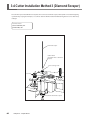
3-4 Cutter Installation Method 3 (Diamond Scraper)................................................................... 48
Installing a Diamond Scraper...................................................................................................................................................49
Cutting Parameters for the Diamond Scraper....................................................................................................................52
1
Contents
3-5 Cutter Installation Method 4 (End Mill)................................................................................. 53
Installing an End Mill...................................................................................................................................................................54
3-6 Loading Material and Setting the Reference Point for Cutting.............................................. 57
Loading Material...........................................................................................................................................................................57
The Loaded Position of the Workpiece.................................................................................................................................58
Setting the Reference Point for the Cutting Position......................................................................................................58
Chapter 4 Performing CuttingUsing a Computer......................................................................... 59
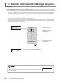
4-1 Procedures for Performing Cutting Using a Computer........................................................ 60
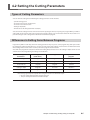
4-2 Setting the Cutting Parameters............................................................................................ 61
Types of Cutting Parameters....................................................................................................................................................61
Differences in Setting Items Between Programs..............................................................................................................61
Making the Settings on the Machine....................................................................................................................................62
4-3 Installation and Overview of the Included Software.............................................................. 64
Software Included with the Machine....................................................................................................................................64
Installation and Setup.................................................................................................................................................................64
4-4 Executing Cutting Data Saved on a Memory Card ............................................................. 67
Working with Cutting Data on a Memory Card ................................................................................................................67
Requirements for Saving Cutting Data ................................................................................................................................67
Saving Cutting Data....................................................................................................................................................................68
Importing and Executing Memory-card Data ...................................................................................................................71
Important Notes When Saving Cutting Data ....................................................................................................................72
Chapter 5 The TeachingFeature..................................................................................................... 73
5-1 Overview of the Teaching Feature....................................................................................... 74
What Is the Teaching Feature?.................................................................................................................................................74
Important Notes When Using the Nose Unit......................................................................................................................74
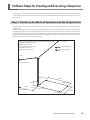
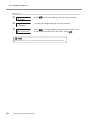
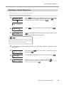
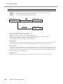
5-2 Basic Steps for Creating and Executing a Sequence........................................................... 75
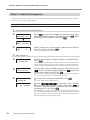
Step 1
Step 2
Step 3
Step 4
Decide on the Mode of Operation and the Origin Points...............................................................................75
Create the Sequence....................................................................................................................................................76
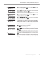
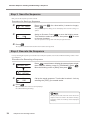
Save the Sequence .......................................................................................................................................................78
Execute the Sequence .................................................................................................................................................78
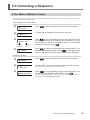
5-3 Correcting a Sequence........................................................................................................ 79
If You Make a Mistake in Input.................................................................................................................................................79
Revising a Saved Sequence......................................................................................................................................................81
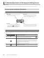
5-4 Detailed Description of the Sequence Editing Screen.......................................................... 82
Screen Layout and Button Operations.................................................................................................................................82
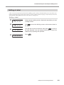
Setting a Label...............................................................................................................................................................................83
5-5 Detailed Information on Saving a Sequence........................................................................ 84
Destinations for Saving Sequences.......................................................................................................................................84
Backing Up a Sequence..............................................................................................................................................................85
Deleting a Sequence...................................................................................................................................................................86
5-6 Coordinate Systems Used with the Teaching Feature......................................................... 87
Cutting Positions Used with the Teaching Feature..........................................................................................................87
Optional Origins............................................................................................................................................................................87
I Level and R Level........................................................................................................................................................................88
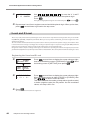
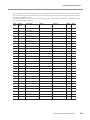
5-7 List of Commands................................................................................................................ 89
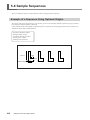
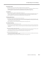
5-8 Sample Sequences............................................................................................................ 100
Example of a Sequence Using Optional Origins............................................................................................................ 100
Chapter 6Detailed Description of Functions............................................................................... 103
6-1 Coordinate Systems and Origin Points.............................................................................. 104
Workpiece Coordinates and Machine Coordinates...................................................................................................... 104
The Machine's Workpiece Origin Point.............................................................................................................................. 104
Unit of Measurement for Coordinate Values................................................................................................................... 104
2
Contents
6-2 Detailed Description of the Nose Unit................................................................................ 105
Amount of Height Displacement That Can Be Tracked............................................................................................... 105
Limitations on Cutting............................................................................................................................................................. 105
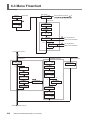
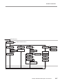
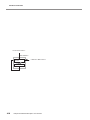
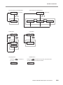
6-3 Menu Flowchart................................................................................................................. 106
6-4 Detailed Description of the Menus..................................................................................... 110
Main Menu................................................................................................................................................................................... 110
[I/O] Submenu............................................................................................................................................................................ 111
[OTHERS] Submenu.................................................................................................................................................................. 112
[SELF] Submenu......................................................................................................................................................................... 113
Teaching Menu........................................................................................................................................................................... 114
[RUN] Submenu......................................................................................................................................................................... 116
X/Y-axis Origin-point Setting Menu.................................................................................................................................... 117
Z-axis Origin-point Setting Menu........................................................................................................................................ 117
Pause Menu................................................................................................................................................................................. 117
Copy Menu................................................................................................................................................................................... 118
Language Menu......................................................................................................................................................................... 118
Initialize Menu............................................................................................................................................................................ 118
Chapter 7 Maintenance................................................................................................................. 119
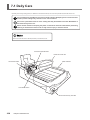
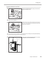
7-1 Daily Care.......................................................................................................................... 120
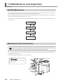
7-2 Maintenance and Inspection.............................................................................................. 122
Spindle Maintenance............................................................................................................................................................... 122
Maintenance of the Z-axis Screw ........................................................................................................................................ 122
Chapter 8 Troubleshooting........................................................................................................... 123
8-1 Problems with Engraving................................................................................................... 124
8-2 Problems with Operation.................................................................................................... 126
8-3 Responding to an Error Message...................................................................................... 128
Chapter 9 Appendix....................................................................................................................... 133
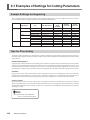
9-1 Examples of Settings for Cutting Parameters.................................................................... 134
Sample Settings for Engraving............................................................................................................................................. 134
Tips for Fine-tuning.................................................................................................................................................................. 134
9-2 The Nose Unit.................................................................................................................... 135
Considerations for Fluctuations in Workpiece Thickness............................................................................................ 135
Structure of the Nose Unit..................................................................................................................................................... 135
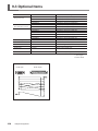
9-3 Optional Items.................................................................................................................... 136
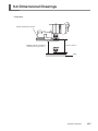
9-4 Dimensional Drawings....................................................................................................... 137
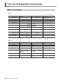
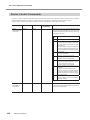
9-5 List of Supported Commands............................................................................................ 138
RML-1 Commands..................................................................................................................................................................... 138
Device Control Commands.................................................................................................................................................... 140
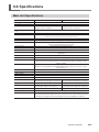
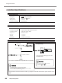
9-6 Specifications..................................................................................................................... 141
Main Unit Specifications......................................................................................................................................................... 141
Interface Specifications........................................................................................................................................................... 142
Windows and Windows NT are registered trademarks or trademarks of Microsoft® Corporation
in the United States and/or other countries.
Pentium are registered trademarks of Intel Corporation in the United States.
IBM is a registered trademark of International Business Machines Corporation.
Multi Media Card is a trademark of Infineon Technologies AG.
Other company names and product names are trademarks or registered trademarks of their respective holders.
Copyright© 2002-2012 Roland DG Corporation
http://www.rolanddg.com/
3
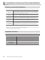
About the Documentation for This Machine
Documentation Included with the Machine
User's Manual (this manual)
This describes important notes for ensuring safe use, and explains how to install the machine and how to install and set up
the included programs. Be sure to read it first.
It does not describe how to operate your computer or how to use the programs.
Dr. Engrave User's Manual (electronic-format manual)
This manual explains how to use the included engraving program. It describes procedures ranging from how to design a
nameplate or the like to engraving operations. Read it if you're using this program.
The manual is in electronic format, and no printed document is included. You can find it on the included Roland Software
Package CD-ROM.
3D Engrave User's Manual (electronic-format manual)
This manual explains how to use the included program for three-dimensional engraving and for creating reliefs. It describes
procedures ranging from how to design reliefs and the like to cutting operations. Read it if you're using this program.
The manual is in electronic format, and no printed document is included. You can find it on the included Roland Software
Package CD-ROM.
Cutting Tips (electronic-format manual)
This is a collection of hints and tips for the procedures of three-dimensional cutting. Read it as a reference when you're cutting three-dimensional objects.
Like the other manuals in electronic format, it is a PDF document, and Acrobat Reader is required to view it. You can find it
on the Roland Software Package CD-ROM, inside [Document], in the [Cuttips] folder.
Other Information
For descriptions of other programs and drivers, refer to the online help.
4
Contents
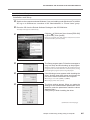
Viewing Manuals in Electronic Format
You can view the manuals in electronic format on a computer running Windows (Windows 95 or later).
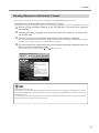
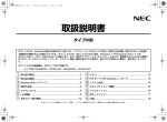
Procedures for Viewing Manuals in Electronic Format
Place the Roland Software Package in the CD-ROM drive. The menu screen appears
automatically.
Click the [Click here] message, then choose the name of the model you're using (EGX600 or EGX-400).
Click the [?] button. Acrobat Reader starts and the user's manual is displayed.
You can use the left and right arrow keys on the computer keyboard to advance to the next
page or go back to the previous page.
When you click the button for the first time, the program for installing and setting up Acrobat Reader may start. Follow the on-screen instructions to proceed with installation and setup.
You can also do the same thing using the [ ] and [ ] buttons on screen.
EGX-600
About Adobe Acrobat Reader
Acrobat Reader is a program required to view files in PDF format. Installing and setting up Acrobat Reader 4.0, found on
the included CD-ROM, lets you view the manual easily on any computer. Acrobat Reader 4.0 is available in versions for
Windows 95 or later.
* Acrobat Reader is a product of Adobe Systems Incorporated. For detailed information on how to use it, go to the Acrobat
Reader menu and select [Help] to view the online help.
5
To Ensure Safe Use
About
WARNING and
WARNING
CAUTION Notices
Used for instructions intended to alert the user to the risk of death or severe injury
should the unit be used improperly.
Used for instructions intended to alert the user to the risk of injury or material
CAUTION
damage should the unit be used improperly.
* Material damage refers to damage or other adverse effects caused with respect
to the home and all its furnishings, as well to domestic animals or pets.
About the Symbols
The
symbol alerts the user to important instructions or warnings. The specific meaning of
the symbol is determined by the design contained within the triangle. The symbol at left means
"danger of electrocution."
The
symbol alerts the user to items that must never be carried out (are forbidden). The specific
thing that must not be done is indicated by the design contained within the circle. The symbol at
left means the unit must never be disassembled.
The
symbol alerts the user to things that must be carried out. The specific thing that must be
done is indicated by the design contained within the circle. The symbol at left means the powercord plug must be unplugged from the outlet.
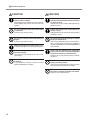
WARNING
Do not disassemble, repair, or modify.
Doing so may lead to fire or abnormal operation resulting in injury.
Ground the unit with the ground wire.
Failure to do so may result in risk of electrocution in the event of a mechanical problem.
Do not use with any electrical power supply
that does not meet the ratings displayed
on the unit.
Use with any other power supply may lead to
fire or electrocution.
Do not use while in an abnormal state (i.e.,
emitting smoke, burning odor, unusual
noise, or the like).
Doing so may result in fire or electrocution.
Immediately switch off the power, unplug the
power cord from the electrical outlet, and contact your authorized Roland DG Corp. dealer
or service center.
Use only with the power cord included with
this product.
Use with other than the included power cord
may lead to fire or electrocution.
6
WARNING
To Ensure Safe Use
CAUTION
Do not use with a damaged power cord or
plug, or with a loose electrical outlet.
Doing so may lead to fire, electrical shock, or
electrocution.
When not in use for extended periods,
unplug the power-cord plug from the electrical outlet.
Failure to do so may result in danger of
electrical shock, electrocution, or fire due to
deterioration of electrical insulation.
Do not attempt to unplug the power-cord
plug with wet hands.
Doing so may result in electrical shock or
electrocution.
Install on a stable surface.
Failure to do so may result in the unit tipping
over, leading to injury.
When you're finished, wash your hands to
rinse away all cuttings.
CAUTION
Do not damage or modify the electrical
power cord, subject it to excessive bending, twisting, pulling, binding, or pinching,
or place any object or weight on it.
Doing so may damage the electrical power
cord, leading to fire, electrical shock, or electrocution.
When unplugging the electrical power cord
from the power outlet, grasp the plug, not
the cord.
Unplugging by pulling the cord may damage
it, leading to fire, electrical shock, or electrocution.
Do not allow liquids, metal objects or flammables inside the machine.
Such materials can cause fire.
Perform dry cutting with no cutting oil.
Such materials can cause fire.
Please use a vacuum cleaner to remove
cutting dust.Do not use any blower like
airbrush.
Otherwise, dust spread in the air may harm
your health.
7
To Ensure Safe Use
CAUTION
CAUTION
Use a commercially available brush to
remove metal cuttings.
Attempting to use a vacuum cleaner to take up
metal cuttings may cause fire in the vacuum
cleaner.
Unpacking, installation, and moving are
operations that must be carried out by four
or more persons.
Failure to do so may result in falling of the unit,
leading to injury.
Do not carelessly insert the hands while
in operation.
Doing so may result in injury.
Fasten the spindle, tool, and material securely in place.
Otherwise they may come loose during cutting,
resulting in injury.
Do not touch the tip of the blade with your
fingers.
Doing so may result in injury.
Do not operate beyond capacity or subject
the tool to undue force.
The tool may break or fly off in a random direction. If cutting beyond capacity is mistakenly
started, immediately turn off the EMERGENCY
STOP switch.
Wear dust goggles and mask during use.
Cutting dust may vcatter, causing bodily injury.
Do not wear gloves, a necktie or widesleeved clothing.
They may become caught in the tool, resulting in injury.
Do not operate if a spindle cover is cracked
or broken.
If the spindle is cracked, contact a service
agent immediately for repairs.
Switch off the machine and unplug the
power cord from the electrical outlet before
performing cleaning or maintenance.
Failure to do so may result in injury or electrical shock.
Do not touch the tool immediately after
cutting operating stops.
The tool may have become hot due to friction
heat and may cause burns if touched.
Do not touch the spindle motor immediately after a cutting operation has ended.
Doing so may result in burns.
8
To Ensure Safe Use
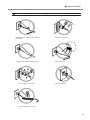
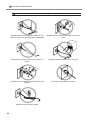
Important notes about the power cord, plug, and electrical outlet
Never place any object on top or subject
to damage.
Never bend or twist with undue force.
Never pull with undue force.
Never allow to get wet.
Never make hot.
Dust may cause fire.
Never bundle, bind, or roll up.
9
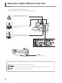
About the Labels Affixed to the Unit
These labels are affixed to the body of this product.
The following figure describes the location and content of these messages.
Caution: high temperatures. Do not touch immediately after a cutting operation has ended.
Use care to avoid being pinched. Keep hands
away during operation.
Use caution when handling or working with
the blade. Careless handling may result in
injury.
Model name
Rating plate
Use a rated power supply.
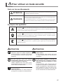
In addition to these symbols, the symbols shown below are also used.
: Indicates information to prevent machine breakdown or malfunction and ensure correct use.
10
: Indicates a handy tip or advice regarding use.
Pour utiliser en toute sécurité
Avis sur les avertissements
ATTENTION
Utilisé pour avertir l'utilisateur d'un risque de décès ou de blessure grave en cas
de mauvaise utilisation de l'appareil.
Utilisé pour avertir l'utilisateur d'un risque de blessure ou de dommage matériel
PRUDENCE
en cas de mauvaise utilisation de l'appareil.
w
* Par dommage matériel, il est entendu dommage ou tout autre effet
indésirable sur la maison, tous les meubles et même les animaux domestiques
À propos des symboles
Le symbole
attire l'attention de l'utilisateur sur les instructions importantes ou les
avertissements. Le sens précis du symbole est déterminé par le dessin à l'intérieur du triangle. Le
symbole à gauche signifie "danger d'électrocution".
Le symbole
avertit l'utilisateur de ce qu'il ne doit pas faire, ce qui est interdit. La chose
spécifique à ne pas faire est indiquée par le dessin à l'intérieur du cercle. Le symbole à gauche
signifie que l'appareil ne doit jamais être démonté.
Le symbole
prévient l'utilisateur sur ce qu'il doit faire. La chose spécifique à faire est indiquée
par le dessin à l'intérieur du cercle. Le symbole à gauche signifie que le fil électrique doit être
débranché de la prise.
ATTENTION
ATTENTION
Ne pas démonter, réparer ni modifier.
Démonter, réparer ou modifier l'appareil risque de provoquer un incendie ou de causer
un fonctionnement anormal entraînant des
blessures.
Mettre l'appareil à la terre avec le fil de
mise à la terre.
Ne pas respecter cette consigne peut créer
un risque d'électrocution en cas de panne
mécanique.
Ne pas utiliser avec une source
d'alimentation électrique non conforme à
la norme indiquée sur l'appareil.
Utiliser l'appareil avec une autre source
d'alimentation risque de provoquer un incendie
ou de causer une électrocution.
Ne pas utiliser l'appareil s'il est dans un
état anormal (p.ex., émission de fumée,
odeur de brûlé, bruit inhabituel ou autre
anomalie).
Ne pas respecter cette consigne risque de
provoquer un incendie ou une électrocution.
Couper immédiatement l'alimentation électrique, débrancher le fil de la prise et communiquer avec le revendeur ou le centre de
service autorisés de la société Roland DG.
Utiliser l'appareil uniquement avec le fil
électrique fourni.
Utiliser l'appareil avec un autre fil risque de
provoquer un incendie ou une électrocution.
11
Pour utiliser en toute sécurité
PRUDENCE
Ne pas utiliser si le fil ou la fiche électriques
sont endommagés; ne pas brancher dans
une prise mal fixée.
Négliger de suivre cette consigne risque
de provoquer un incendie ou decauser une
décharge électrique ou une électocution.
Si l'appareil reste inutilisé pendant de
longues périodes, débrancher la fiche de
la prise.
Négliger de suivre cette consigne peut
créer un risque de décharge électrique ou
d'électrocution ou provoquer un incendie à
cause de la détérioration de l'isolant électrique.
Ne pas débrancher le fil avec des mains
mouillées.
Ne pas respecter cette consigne risque de
provoquer des décharges électriques ou une
électrocution.
IInstaller sur une surface stable.
Sinon, l'appareil risque de se renverser et de
causer des blessures.
Quand vous avez terminé d'utiliser
l'appareil, laver vos mains pour bien enlever tous les copeaux.
12
PRUDENCE
Ne pas endommager ni modifier le fil électrique. Ne pas le plier, le tordre, l'étirer,
l'attacher ou le serrer de façon excessive.
Ne pas placer d'objet ou de poids sur le fil.
Négliger de suivre cette consigne peut endommager le fil électrique, ce qui risque de provoquer un incendie ou de causer une décharge
électrique ou une électrocution.
Pour débrancher l'appareil, saisir la fiche
et non le fil électrique.
Tirer sur le fil peut l'endommager, ce qui risque
de provoquer un incendie ou de causer une
décharge électrique ou une électrocution.
Ne pas laisser de liquides ni d'objets métalliques ou inflammables s'infiltrer dans
l'appareil.
De telles infiltrations peuvent provoquer un
incendie.
Perform dry cutting with no cutting oil.
Such materials can cause fire.
Utiliser un aspirateur pour nettoyer les copeaux. N'utiliser aucun appareil soufflant
de l'air comme un sèche-cheveux.
La poussière répandue dans l'air pourrait nuire
à votre santé.
Pour utiliser en toute sécurité
PRUDENCE
PRUDENCE
Utiliser une brosse du commerce pour
retirer les rognures de métal.
Tenter de retirer les rognures de métal à l’aide
d’un aspirateur peut faire naître un incendie
dans l’aspirateur.
Lorsque vous déplacez l'appareil, le saisir
par sa base en aluminium et le transporter
à 4 personnes ou plus.
Si l'appareil est saisi par la plaque du dessus,
il peut tomber et entraîner des blessures.
Faire attention de ne pas insérer ses mains
pendant le fonctionnement.
Ne pas respecter cette consigne peut provoquer des blessures.
Fixer fermement le mandrin, l'outil et le
matériel à leur place.
Sinon, ces éléments risquent d'avoir du jeu
lors des coupes, ce qui entraînerait des blessures.
Ne pas toucher à l’extrémité de la lame
avec vos doigts.
Vous risqueriez de vous blesser en y touchant.
Porter des lunettes de travail et un masque
durant l'utilisation.
Des copeaux pourraient être projetés et vous
blesser.
Ne pas porter de gants, de cravate ou de
vêtement à manches amples.
Ils pourraient se prendre dans l'appareil et
entraîner des blessures.
N'utilisez pas l'appareil si le couvercle de
l'axe est fissuré ou brisé.
Si le couvercle de l'axe est fissuré, communiquez immédiatement avec un agent de service
pour faire effectuer les réparations.
Ne pas utiliser l'appareil au-dessus de
ses capacités ou le soumettre à une force
excessive.
L'outil pourrait se briser ou être projeté
dans une direction indéterminée. Si vous
commencez par inadvertance une coupe audessus de la capacité de l'appareil, l'éteindre
immédiatement à l'aide du bouton d'urgence.
Couper le contact et débrancher le câble
d’alimentation du réceptacle avant de
procéder au nettoyage ou à l’entretien de
l’appareil.
Une négligence à ce niveau pourrait provoquer
des blessures ou une électrocution.
Ne pas toucher l'outil immédiatement après
une coupe.
L'outil pourrait avoir chauffé avec la friction et
vous causer des brûlures.
Ne touchez pas le moteur de l'axe immédiatement après avoir terminé une coupe.
Vous risqueriez alors de vous brûler.
13
Pour utiliser en toute sécurité
Important notes about the power cord, plug, and electrical outlet
Ne jamais déposer aucun objet sur le câble, sur la ficheou sur la prise car cela risque de les endommager.
Ne jamais laisser l'eau toucher le câble, la fiche ou la
prise.
Ne jamais plier ni tordre le câble avec une force excessive.
Ne jamais chauffer le câble, la fiche ou la prise.
Ne jamais tirer sur le câble ou la fiche avec une force
excessive.
La poussière peut causer un incendie.
Ne jamais plier ni enrouler le câble.
14
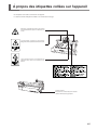
À propos des étiquettes collées sur l'appareil
Ces étiquettes sont collées à l'extérieur de l'appareil.
Les dessins suivants indiquent l'endroit et le contenu des messages.
Attention : températures élevées. Ne touchez
pas immédiatement après avoir effectué une
coupe.
Soyez prudent et évitez les pincements.
Éloignez les mains pendant le fonctionnement.
Soyez prudent lorsque vous manipulez ou
utilisez la lame, sinon vous risquez de vous
blesser.
Nom du modèle
Étiquette des caractéristiques électriques
Utiliser l'alimentation appropriée
15
16
Chapter 1
Getting Started
This chapter describes the procedures extending from unpacking the
machine to installing it, and also explains such matters as required
terminology and other background knowledge.
17
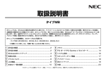
1-1 Including Items and Accessories
Follow the steps in "Unpacking and Repacking" on the packing carton to take out the included items and accessories.
Before you attempt installation, make sure all the included items are present.
Operation panel :1
Operation panel
connector cable :1
Power cord :1
Depth regulator
nose unit :1
Nut
Bolt
Solid collet :1(*1)
Solid collet for diamond
scrapers :1(*2)
Clamps :4(*3)
Wrenches
(17 mm : 1, 10 mm :1)
Hexagonal screw driver
(2 mm) :1
Hexagonal wrench
(3 mm) :1
Roland Software Package
CD-ROM :1
User's Manual
(this manual) :1
*1 This is for diameter-4.36 mm character or flat cutters. It cannot be used with diamond scrapers or end mills.
*2 The solid collet for diamond scrapers can also be used with a character cutter or flat cutter, but do not use it at a speed of
15,000 rpm or higher. There is danger of damage to the spindle unit due to vibration.
*3 The bolts adn nuts are installed on the machine.(They are used for attacking the packing retainers.)
*This machine does not come with a cutter or cutter holder
18
Chapter 1 Getting Started
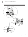
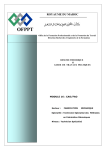
1-2 Names and Functions
Front
Spindle cover
Pulley
Lock nut
Belt
Spindle motor
Spindle unit
Depth regulator nose unit
(Nose unit)
Rail cover
X-axis rail
Spindle head
Arm
T slot
Bed
Guide
Table
Slot cover
Operation-panel
connector
Memory-card slot
Emergency stop
switch
Guide securing
screws
Micrometer dial
Depth regulator
nose unit
(Nose unit)
Nose cone
Retainer nut
Chapter 1 Getting Started
19
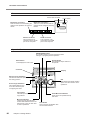
1-2 Names and Functions
Rear
Power-cord connector
Expansion connector 1
This connector is for transmitting the
rotation of the spindle to an external
device.
Power switch
Expansion connector 2
This is for communication with an
external device using the teaching
feature.
Parallel connector
This connector is for
connection to the printer
port on the computer.
Serial connector
This connector is for
connection to the COM
port on the computer.
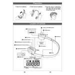
Operation Panel
ENTER/PAUSE button
This enables values you enter. Pressing it while
cutting is in progress pauses operation.
Menu button
This displays the main menu.
Spindle button
This starts and stops rotation of
the spindle.
Connector
Display
X/Y-axis Origin Set button
This sets the reference point for
the cutting position.
Dial
This adjusts the spindle rotating
speed. It is also used for menu
operations.
Z-axis Origin Set button
This makes settings such
as for the reference point
for aligning the cutter.
Copy botton
This calls up the menu for the
copy feature.
Movement buttons
These move the spindle head
forward and backward and to the
left and right. They are also used
for menu operations.
20
Chapter 1 Getting Started
Z-axis Movement buttons
These move the spindle head up
and down.
Feed button
This is used in combination with
the movement buttons.
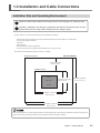
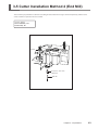
1-3 Installation and Cable Connections
Instllation Site and Operating Environment
Install on a stable surface.Failure to do so may result in the unit tipping over, leading to injury
Unpackig , installation, and moving are operatioins that must be carried out by four or more
persons. Failure to do so may result in falling of the unit, leading to injury.
Use this mahcine in an environment that meets th efollowing conditions.
• Temperature of 5 to 40°C (41 to 104 °F) and relative humidity of 35 to 85% (with no condensation).
• A level location with no wobble.
• Little dust.
• Little vibration.
• Good ventilation and heat dissipation.
• Low electrical noise. For example, avoid installing near an electric motor.
Also ensure that the following amount of space is available.
Maintenance space
EGX-600 /EGX-400
900 mm / 900 mm
(35 in./ 35 in.)
Installation space
(Rear)
Main Unit
1200mm / 1000 mm
(48 in./ 40 in.)
2600mm / 2500 mm
(103 in./ 100 in.)
(Front)
1200mm / 1000 mm
(48 in./ 40 in.)
2100mm / 1900 mm
(83 in./ 75 in.)
When the spindle motor is run at high speed while at a low temperature, roation may be unstable for some time. Insuch cases,
allow to warm up by runnning at about 15,000 rpm with no load for around 15 minutes.
Chapter 1 Getting Started
21
1-3 Installation and Cable Connections
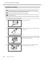
Connecting the Cables
Ground the unit with the ground wire.Failure to do so many result in risk of electrocution in the
event of a mechanical problem.
Use only with the power cord included with this product.Use with other than the included power
cord may lead to fire or electrocution.
Do not use with any electrical power supply that does not meet the ratings displayed on the unit.
Use with any other power supply may lead to fire or electrocution.
Make sure the power to the machine is switched off before attempting to connect
or disconnect the cables. Connect securely to ensure that accrdental disconnection
does not occure during operation.
Conncect the operation panel and the power cable. If you're using a computer, then also connect a printer cable or serial cable.
The ;printer cable or serial cable is sold separately. Use a cable that is compatible with the computer.
Printer cable
Use a commercially available printer cable.
Serial cable
If your cpmputer is as IBM AT-compatible personal computer, then use as optionally available XY-RS-34 cable 8or equivalet).
A straight cable such as a modem cable will not work.
When the connection uses a serial cable, you need to make sure the communication parameters for the machine match
the communication parameters for the computer. For more information about the computer's commnucation parameters,
refer to the documentation for the program. The defaults for the programs included with this machine are set up to match
without modification
Configuring the Communication Parameters for the Machine.
See p.111 "I/O Submenus"
22
Chapter 1 Getting Started
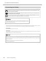
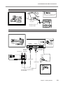
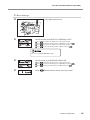
1-3 Installation and Cable Connections
Front
Do not insert an Ethernet cable
or connect ro a modular jack.
Insert until it clicks
into place.
Operation-panel
connector cable
Rear
Power connector
Parallel
connector
Secure with
the clips.
Printer port
Serial
connector
Secure with
the screws.
Serial port
Power
outlet
Printer cable
Serial cable
Power cord
Connect either a printer cable
or serial cable
Chapter 1 Getting Started
23
24
Chapter 2
Basic Operation
This chapter describes what you should know before you try to use
the machine, such as the most basic operations and the procedures
for safe use and handling. Be sure to read this chapter before you
go on to the next step.
Operating the buttons makes the machine move. When operating the
buttons, be sure to keep your hands away from the machine.
Do not let your hair, necktie, or the like touch the machine. There is danger
of becoming it caught on the spindle or other moving parts.
25
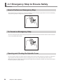
2-1 Emergency Stop to Ensure Safety
How to Perform an Emergency Stop
To stop the machine in an emergency in order to avoid danger, press the emergency stop switch. The machine immediately
stops operating and quits cutting. Cutting cannot be resumed.
To Cancel an Emergency Stop
To cancel an emergency stop, turn the emergency stop switch in the direction of the arrow. The machine returns to the state
it was in immediately after powerup.
Opening and Closing the Spindle Cover
Be sure to close the spindle cover before you start cutting, and never open it while operation is in progress. For safety, opening the spindle cover during operation causes an emergency stop. To recover, switch off the power to the machine.
When the spindle cover is open, only head movement using the movement buttons is possible. You cannot use the buttons
to rotate the spindle or perform cutting.
26
Chapter 2 Basic Operation
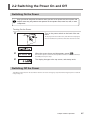
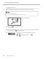
2-2 Switching the Power On and Off
Switching On the Power
Keep your hands away from the machine when you turn on the power. Also, do not place and
objects where they may obstruct the operation of the spindle head, X-axis rail, bed, or other
components.
Turning On the Power
Turn on the power switch on the back of the machine.
The display shows the model name, and while this is displayed,
internal initialization is performed. This takes about ten seconds.
When the screen shown at right appears, press
The display changes to the top screen, and startup ends.
.
This machine operates at this time. The spindle head moves to the left and back (to
the VIEW position), then stops.
Switching Off the Power
Turn off the power switch on the back of the machine. Do not the emergency stop switch for turning the power on and off
in day-to-day use.
Chapter 2 Basic Operation
27
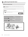
2-3 Moving the Spindle Head
Moving the Spindle Head
Do not put the operation panel on the machine while operation. Doing so may result in unexpected problems.
The spindle head moves in three directions, along the X, Y, and Z axes. When the display shows the top screen, pressing the
movement buttons effects movement in the corresponding directions.
Make sure the display shows the top screen. You cannot perform movement when any other screen is displayed.
Press
several times to display the top screen.
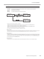
The speed of movement is determined by how you press the movement buttons, as described below.
Pressing and holding down a movement button
While holding down
a movement button
, pressing and holding down
Pressing and releasing a movement button
While holding down
movement button
, pressing and releasing a
Slow continuous movement
Fast continuous movement
Movement of 0.01 mm per press
Moveent of 0.1 mm per press
Y-axis direction
Z-axis direction
X-axis direction
28
Chapter 2 Basic Operation
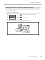
2-3 Moving the Spindle Head
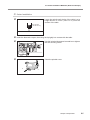
Moving the Spindle Head Out of the Way Quickly
This feature moves the spindle head directly to the back-left position of the table (the VIEW position). This is handy when
loading or detaching a workpiece.
Moving to the VIEW Position
Press
until the screen shown at right appears.
Press
.
Press
.
The blinking cursor moves to [VIEW].
The spindle head rises to the highest point, then moves to the VIEW position.
Chapter 2 Basic Operation
29
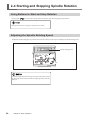
2-4 Starting and Stopping Spindle Rotation
Using Buttons to Start and Stop Rotation
Holding down
for 0.5 seconds or longer makes the spindle rotate. Pressing it again stops rotation.
When the spindle cover is open, the spindle does not rotate.
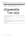
Adjusting the Spindle Rotating Speed
To adjust the spindle rotating speed, you use the dial on the operation panel. The top screen displays the spindle rotating speed.
Spindle rotating speed
Slow
Avoid turning the dial while cutting is in progress. The feed rate drops
momentarily, and the finished results of engraving may be adversely
affected.
30
Chapter 2 Basic Operation
Fast
2-4 Starting and Stopping Spindle Rotation
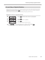
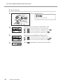
Forced Stop of Spindle Rotation
With this machine, you can set whether or not the spindle rotates. When it is set to rotate, rotation automatically starts when
a command is received from the computer and stops when cutting ends. When set not to rotate, no rotation at all takes place.
(Rotation does not occur even if you press
.)
You use this feature at times such as when you are performing scribing using a diamond scraper.
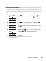
Making the Setting for Spindle Rotation
Press
until the screen shown at right appears.
Press
.
Press
.
The blinking cursor moves to [OTHERS].
The screen for setting spindle rotation appears.
Use
to move the blinking cursor to [ON] or [OFF]. Press
[ON] makes the setting for rotation, and [OFF] makes the setting for forced stop.
.
Chapter 2 Basic Operation
31
2-5 Menu Operations
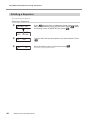
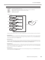
Displaying the Menus
All settings for this machine are made using menus. Pressing the following buttons displays the menu screens.
Main menu
X/Y-axis origin-point setting menu
Pause menu (when pressed during
cutting)
Z-axis origin-point setting menu
Copy menu
For detailed information on using the menus
See p.106 "Menu Flowchart"
See p.110 "Detailed Description of the Menus"
Basic Menu Operations
When you display the menus, the buttons function as follows.
Moving to the next screen
Pressing this several times eventually returns you to the top screen.
Moving the blinking cursor
You use the blinking cursor to select items. In the example at right,
for instance, you can select either [ON] or [OFF].
Raising and lowering numerical values
Pressing either of these buttons while holding down
down the button makes the value change rapidly.
increases or decreases the value by large amounts. Holding
Confirming and executing the selected item
Operations with
A setting is enabled only when you press
do not enable settings, they only select the setting values.
. When you enable a setting, the item is displayed enclosed in "< >."
You also use this button to execute things and display submenus.
32
Chapter 2 Basic Operation
2-6 Care and Handling of Memory Cards
This section describes the basic usage and handling of memory cards.
This machine can execute cutting data saved on a memory card, and can save sequences created using the teaching feature. For more information about these operations, see "Executing Cutting Data Saved on a Memory Card" on p.67 and "The
Teaching Feature" on p.73.
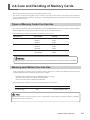
Types of Memory Cards You Can Use
Use commercially available "SD (Secure Digital) Memory Card" or "MultiMediaCard", which are available in sizes of 16 MB, 32
MB, and 64 MB. Note that copyright-protection functions are not used with this machine.
Roland DG Corp. has verified the operation of the following memory cards.
Manufacturer
SanDisk
Panasonic
HAGIWARA SYS-COM
Part number
Capacity
SDMB-16
16 MB
SDMB-32
32 MB
SDMB-64
64 MB
RP-SD016
16 MB
RP-SD032
32 MB
RP-SD064
64 MB
HPC-MC32M
32 MB
HPC-MC64M
64 MB
This machine does not detect the write-protect switch on an SD Memory Card, even when the switch is set to "LOCK."
Memory-card Writers You Can Use
To save cutting data on a memory card or to format a memory card, you use a commercially available memory-card writer
or adapter. One that meets the following specifications is required.
• Compatible with "SD Memory Card" or "MultiMediaCard" you're using
• Able to be connected to your computer running Windows
• Able to read and write files compatible with Windows
Roland DG Corp. has verified the operation of the following memory-card writers.
Manufacturer
Part number
Operating environment
VICS Technology
RD5
Windows 98/Me/2000/XP
Windows must be able to treat the memory card as a single volume. Nearly all memory-card writers that are compatible
with Windows meet this requirement.
Chapter 2 Basic Operation
33
2-6 Care and Handling of Memory Cards
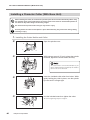
Inserting and Removing a Memory Card
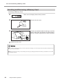
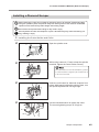
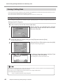
Inserting a Memory Card
Make sure the display shows the top screen.
Remove the slot cover.
Hold the card with the label side facing up and the
notch on the right, and insert it into the memorycard slot. Press it in gently until it clicks into place.
Attach the slot cover.
◆Be careful to orient the memory card correctly when inserting it. An incorrectly inserted card will not function and
may even cause breakdown.
◆Before you insert a memory card, carefully clean away any cutting waste from the memory card and the area around
the memory-card slot.
34
Chapter 2 Basic Operation
2-6 Care and Handling of Memory Cards
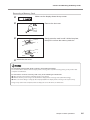
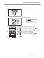
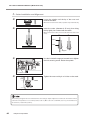
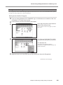
Removing a Memory Card
Make sure the display shows the top screen.
Remove the slot cover.
Gently press the card in until it clicks into place,
then pull it out from the memory-card slot.
1.
2.
Attach the slot cover.
Do not switch off the power while a memory card is being accessed.
Do not switch off the machine while the display shows a message such as [Now Processing]. Doing so may result in data
corruption or malfunction.
Do not insert or remove a memory card in any of the following circumstances.
◆ After you turn on the machine and before the top screen appears
◆ While the memory card is being accessed (When the display shows a message such as [Now Processing])
◆ While a screen for dating or calling up data is displayed (When the display shows a message such as [Select File])
Doing so may result in data corruption, failure to display the correct file names, or malfunction.
Chapter 2 Basic Operationv
35
2-6 Care and Handling of Memory Cards
Formatting a Memory Card
Formatting a memory card is normally not necessary. However, the machine may be unable to use a memory card that has
been reformatted for use with another device, such as a digital camera. In such cases, use the following method to reformat
the card again.
Formatting deletes all data saved on the memory card. Before you format the card, make sure that it contains no data
you want to keep.
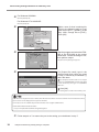
Performing Formatting
To perform formatting, you use a memory-card writer. For information on the specific method, refer to the
documentation for the memory-card writer you're using. Also, give attention to the following points when formatting.
For a MultiMediaCard
Use the standard formatter for Windows. (That is, use the same operation as for formatting a floppy disk.) Depending on t
he version of Windows you're using, you may be able to choose the file system to use for formatting. In such cases,
be sure to select FAT. Do not format as FAT32 or NTFS.
For an SD (Secure Digital) Memory Card
Perform formatting using the same method as for a MultiMediaCard. If a dedicated SD formatter is available, then use
that.
36
Chapter 2 Basic Operation
Chapter 3
Preparations
This chapter describes how to install a cutter, how to load a workpiece, and other preparations you make before you carry out cutting.
37
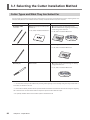
3-1 Selecting the Cutter Installation Method
Cutter Types and What They Are Suited For
You can install any of a wide variety of tools on this machine. You can also choose whether to use the depth regulator nose
unit (nose unit). Choose a tool suited to the task at hand, and decide whether to use the nose unit.
Tool
With nose unit
Character cutter
Flat cutter
Engraving acrylic and other plastic
plates (*1)
P. 39, “Cutter Installation Method 1”
Diamond scraper (*2)
Unsuitable
No nose unit
Engraving plates of aluminum or brass
Three-dimensional engraving and creating
reliefs using plastic materials
P. 44, “Cutter Installation Method 2”
Scribing plates of aluminum or brass (*2)
P. 48, “Cutter Installation Method 3”
End mill (*3)
Unsuitable
Creating reliefs and performing 3D cutting
using plastic material
P. 53, “Cutter Installation Method 4”
*1
Use of the nose unit may not be suitable when performing raised engraving of text or flat-drag cutting over a large surface area. In
such cases, use without the nose unit.
*2 This is suited to relatively small text and can produce finished results that are more attractive and have less burring than engraving
with a character cutter. The solid collet for diamond scrapers is required to install a diamond scraper.
*3: An optionally available collet set for end-mills is required to install and end mill
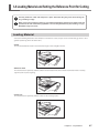
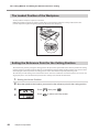
38
Chapter 3 - Preparations
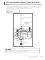
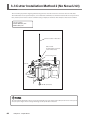
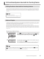
3-2 Cutter Installation Method 1 (With Nose Unit)
This is for when you perform engraving using the nose unit on an acrylic plate or the like. The tip of the nose traces the
material surface, which facilitates obtaining a uniform cutting-in depth. The tool used is a character cutter or a flat cutter.
This method is not suitable for aluminum, brass, or other materials that are easily scratched.
Lock nut : Loosen
[AUTO Z CONTROL] : ON
[REVOLUTION] : ON
Character cutter or flat cutter
Cutter holder
(included with a character
cutter or flat cutter)
Tool securing screw
Lock nut
Solid collet
The solid collet for diamond scrapers can also be used with a character cutter or flat cutter, but do not use it at a speed of
15,000 rpm or higher. There is danger of damage to the spindle due to vibration.
Chapter 3 - Preparations
39
3-2 Cutter Installation Method 1 (With Nose Unit)
Installing a Character Cutter (With Nose Unit)
While installing the cutter, do not allow the operation panel to be touched inadvertently. When using
the operation panel, keep hands away from moving areas of the machine. Unintended operation of
the machine may lead to danger of becoming caught.
Do not touch the tip of the cutter. Doing so may result in injury.
Securely fasten the cutter and workpiece in place. Otherwise they may come loose during cutting,
resulting in injury.
1. Installing the Cutter Holder and Collet
Open the spindle cover.
3.
2.
1.
While using a wrench (17 mm) to keep the spindle
immobile, tighten the cutter holder securely.
The cutter holder is reverse-threaded (that is, you
turn it counterclockwise to tighten it). Be careful to
turn it in the correct direction.
40
Insert the included solid collet from below. While
gently holding the collet in place, turn the spindle
by hand until it is finger-tight.
Use the included wrench to tighten the collet.
Chapter 3 Preparation
The correct tightening torque is 32 kgf-cm.
3-2 Cutter Installation Method 1 (With Nose Unit)
2. Nose-unit Installation and Menu Settings
Install the nose unit. Tighten fully, then loosen two
turns.
Fully loosen the lock nut.
Be sure to loosen the lock nut.
Use the menus to set [AUTO Z CONTROL] to ON.
Press
Press
Press
Press
.
Use the menu to set [REVOLUTION] to ON.
Press
Press
Press
several times to display the screen shown at right.
to move the blinking cursor to [OTHERS], then press
several times to display the screen shown at right.
to move the blinking cursor to [ON], then press
.
Press
several times to display the screen shown at right.
to move the blinking cursor to [OTHERS], then press
to move the blinking cursor to [ON], then press
.
.
several times to return to the top screen.
Chapter 3 Preparation
41
3-2 Cutter Installation Method 1 (With Nose Unit)
3. Cutter Installation and Alignment
Lower the spindle until the tip of the nose unit
touches the table.
When the nose touches the table, operation stops automatically.
Insert the cutter (diameter 4.36 mm), then bring
the tip lightly into contact with the table.
When you insert the cutter, orient it so that it will not catch on the
collet.
Yes
No
Cutter
Collet
Stopper
Use the included hexagonal screwdriver to tighten
the tool securing screw. Raise the spindle.
Tighten the nose unit by 4 to 8 ticks on the scale.
The amount you tighten the nose unit determines the cutting-in depth. Adjust it to suit the task. An amount of 4 to 8
scale ticks corresponds to 0.1 to 0.2 mm (0.004 to 0.008 in.). One scale tick is 0.0254 mm (0.001 in.), and one full turn is
25 scale ticks, or 0.635 mm (0.025 in.).
42
Chapter 3 Preparation
3-2 Cutter Installation Method 1 (With Nose Unit)
Close the spindle cover.
1.
3.
2.
Cutting Parameters When Using the Nose Unit
When you use the preceding method, there is no need to set the cutting-in depth or the cut-out amount by a software or the
operation panel. The cutting-in depth is determined mechanically by the amount of tightening of the nose unit.
For more information about how to set the cutting parameters
See p.61 "Setting the Cutting Parameters"
See p.134 " Examples of Settings for Cutting Parameters"
For detailed information about the nose unit
See p.110 "Detailed Description of the Menus," the section " AUTO Z CONTROL "
See p.105 "Detailed Description of the Nose Unit"
Chapter 3 Preparation
43
3-3 Cutter Installation Method 2 (No Nose Unit)
This is for when you perform engraving without using the nose unit. The tool used is a character cutter or a flat cutter.
This method does not scrape the workpiece, so it is suitable for aluminum, brass and other materials that are easily scratched.
Note, however, that in order to obtain a uniform cutting-in depth, the thickness of the workpiece must also be uniform.
Lock nut : Tighten
[AUTO Z CONTROL] : OFF
[REVOLUTION] : ON
Character cutter or flat cutter
Cutter holder
(included with a character
cutter or flat cutter)
Tool securing screw
Lock nut
Solid collet
The solid collet for diamond scrapers can also be used with a character cutter or flat cutter, but do not use it at a speed
of 15,000 rpm or higher. There is danger of damage to the spindle due to vibration.
44
Chapter 3 - Preparations
3-3 Cutter Installation Method 2 (No Nose Unit)
Installing a Character Cutter (With No Nose Unit)
While installing the cutter, do not allow the operation panel to be touched inadvertently. When
using the operation panel, keep hands away from moving areas of the machine. Unintended
operation of the machine may lead to danger of becoming caught.
Do not touch the tip of the cutter. Doing so may result in injury.
Securely fasten the cutter and workpiece in place. Otherwise they may come loose during cutting, resulting in injury.
1.
Installing the Cutter Holder and Collet
Open the spindle cover.
3.
2.
1.
While using a wrench (17 mm) to keep the spindle
immobile, tighten the cutter holder securely.
The cutter holder is reverse-threaded (that is, you
turn it counterclockwise to tighten it). Be careful to
turn it in the correct direction.
Insert the included solid collet from below. While
gently holding the collet in place, turn the spindle
by hand until it is finger-tight.
Use the included wrench to tighten the collet.
The correct tightening torque is 32 kgf-cm.
Chapter 3 Preparation
45
3-3 Cutter Installation Method 2 (No Nose Unit)
2. Menu Settings
Fully tighten the lock nut.
Use the menu to set [AUTO Z CONTROL] to OFF.
Press
Press
Press
Press
several times to display the screen shown at right.
to move the blinking cursor to [OTHERS], then press
several times to display the screen shown at right.
to move the blinking cursor to [OFF], then press
.
Be sure to set [AUTO Z CONTROL] to OFF.
Use the menu to set [REVOLUTION] to ON.
Press
Press
Press
46
Chapter 3 Preparation
Press
several times to display the screen shown at right.
to move the blinking cursor to [OTHERS], then press
to move the blinking cursor to [ON], then press
.
several times to return to the top screen.
.
3-3 Cutter Installation Method 2 (No Nose Unit)
3. Cutter Installation and Alignment
Load the workpiece, then move the spindle to
above the workpiece. Lower the spindle until the
tip of the collet is at a height about 12 to 13 mm
(1/2 in.) from the surface of the material.
12 to 13 mm (1/2 in.)
Yes
No
Cutter
For more information about how to load material
p.57 "Loading Material and Setting the Reference
Point for Cutting"
Insert the cutter (diameter 4.36 mm), then bring
the tip lightly into contact with the workpiece.
When you insert the cutter, orient it so that it will
not catch on the collet.
If the cutter does not reach the workpiece, lower the spindle
further.
Collet
Stopper
Damage to the workpiece can be prevented by placing a sheet
of thin paper over the workpiece. When you do this it is a good
idea to cut in by a depth increased by an amount equal to the
thickness of the paper (about 0.002 in.).
Use the included hexagonal screwdriver to tighten
the tool securing screw.
Use the menus to set the height reference point
(Z0).
Press
.
Make sure the blinking cursor is at [Z0], then press
Press
to return to the top screen.
.
Close the spindle cover.
1.
3.
2.
Chapter 3 Preparation
47
3-4 Cutter Installation Method 3 (Diamond Scraper)
This is for when you scribe aluminum or brass plates. The tool used is a diamond scraper, and the spindle is not rotated. Engraving
is performed by scraping the workpiece, so it achieves attractive finished results with little burring, but it does not obtain deep
cutting-in.
Lock nut: Loosen
[AUTO Z CONTROL]: ON
[REVOLUTION]: OFF
Diamond scraper
Cutter holder
(included with a diamond
scraper)
Tool securing screw
Lock nut
Solid collet for diamond scrapers
48
Chapter 3 - Preparations
3-4 Cutter Installation Method 3 (Diamond Scraper)
Installing a Diamond Scraper
While installing the cutter, do not allow the operation panel to be touched inadvertently. When
using the operation panel, keep hands away from moving areas of the machine. Unintended
operation of the machine may lead to danger of becoming caught.
Do not touch the tip of the cutter. Doing so may result in injury.
Securely fasten the cutter and workpiece in place. Otherwise they may come loose during cutting, resulting in injury.
1. Installing the Cutter Holder and Collet
Open the spindle cover.
3.
2.
1.
While using a wrench (17 mm) to keep the spindle
immobile, tighten the cutter holder securely.
The cutter holder is reverse-threaded (that is, you turn
it counterclockwise to tighten it). Be careful to turn it
in the correct direction.
Insert the solid collet for diamond scrapers from
below. While gently holding the collet in place, turn
the spindle by hand until it is finger-tight.
Use the included wrench to tighten the collet.
The correct tightening torque is 32 kgf-cm.
Chapter 3 Preparation
49
3-4 Cutter Installation Method 3 (Diamond Scraper)
2. Menu Settings
Fully loosen the lock nut.
Be sure to loosem the lock nut.
Use the menus to set [AUTO Z CONTROL] to ON.
Press
Press
Press
Press
50
Chapter 3 Preparation
.
Use the menus to set [REVOLUTION] to OFF.
Press
Press
Press
several times to display the screen shown at right.
to move the blinking cursor to [OTHERS], then press
several times to display the screen shown at right.
to move the blinking cursor to [ON], then press
.
Press
several times to display the screen shown at right.
to move the blinking cursor to [OTHERS], then press
to move the blinking cursor to [OFF], then press
.
several times to return to the top screen.
.
3-4 Cutter Installation Method 3 (Diamond Scraper)
3. Cutter Installation
Lower the spindle until the tip of the collet is at a
height about 5 to 10 mm (1/4 to 1/2 in.) from the
surface of the table.
5 to 10 mm
(1/4 to 1/2 in.)
Insert the diamond scraper, then bring the tip lightly into contact with the table.
Use the included hexagonal screwdriver to tighten
the tool securing screw.
Close the spindle cover.
1.
3.
2.
Chapter 3 Preparation
51
3-4 Cutter Installation Method 3 (Diamond Scraper)
Cutting Parameters for the Diamond Scraper
When you use the preceding method, there is no need to set the cutting-in depth or the cut-out amount. The cutting-in
depth is determined by the pressure of the cutter. (The preceding method produces a uniform cutter force for the machine.)
For more information about how to set the cutting parameters
See p.61 "Setting the Cutting Parameters"
See p.134 "Examples of Settings for Cutting Parameters"
For detailed information about the cutting-in depth and cut-out amount
See p.110 in "Detailed Description of the Menus," the section "AUTO Z CONTROL"
52
Chapter 3 Preparation
3-5 Cutter Installation Method 4 (End Mill)
This is for when you perform three-dimensional cutting of reliefs and the like using an end mill. An optionally available collet
set for end mills is required to install an end mill.
Lock nut : Tighten
[AUTO Z CONTROL] : OFF
[REVOLUTION] : ON
Lock nut
Collet for end mills
(optional)
End mill
Chapter 3 - Preparations
53
3-5 Cutter Installation Method 4 (End Mill)
Installing an End Mill
While installing the cutter, do not allow the operation panel to be touched inadvertently. When
using the operation panel, keep hands away from moving areas of the machine. Unintended
operation of the machine may lead to danger of becoming caught.
Do not touch the tip of the cutter. Doing so may result in injury.
Securely fasten the cutter and workpiece in place. Otherwise they may come loose during cutting, resulting in injury.
1. Installing the Collet and End Mill
Open the spindle cover.
3.
2.
1.
Insert the end mill into the optionally available
end-mill collet.
20 to 25 mm (3/4 to 1 in.)
54
Insert the end mill and collet from below. While
gently holding the collet in place, turn the spindle
by hand until it is finger-tight.
Use the included wrench to tighten the collet.
Chapter 3 Preparation
The correct tightening torque is 32 kgf-cm.
3-5 Cutter Installation Method 4 (End Mill)
2. Menu Settings
Fully tighten the lock nut.
Use the menus to set [AUTO Z CONTROL] to OFF.
Press
Press
Press
Press
several times to display the screen shown at right.
to move the blinking cursor to [OTHERS], then press
several times to display the screen shown at right.
to move the blinking cursor to [OFF], then press
.
.
Be sure to set [AUTO Z CONTROL] to OFF.
Use the menu to set [REVOLUTION] to ON.
Press
Press
Press
Press
several times to display the screen shown at right.
to move the blinking cursor to [OTHERS], then press
to move the blinking cursor to [ON], then press
.
.
several times to return to the top screen.
Chapter 3 Preparation
55
3-5 Cutter Installation Method 4 (End Mill)
3. Aligning the Cutter
Load a workpiece and move the end mill to the top surface of the material.
For information on how to load material
See p.57 "Loading Material and Setting the Reference Point for Cutting"
Close the spindle cover.
1.
3.
2.
Hold down
Lower the spindle a little at a time, and stop it when it is just barely cutting the surface of
to stop the spindle.
the workpiece. Press
The spindle rotates.
for 0.5 seconds or longer.
Use the menus to set the height reference point (Z0).
Press
.
Make sure the blinking cursor is at [Z0], then press
Press
to return to the top screen.
56
Chapter 3 Preparation
.
3-6 Loading Material and Setting the Reference Point for Cutting
Securely fasten the cutter and workpiece in place. Otherwise they may come loose during cutting, resulting in injury.
When you're using a clamp or other jig, give sufficient thought to positioning so that the tool and
spindle unit do not collide during operation. The tool may break and fly off, resulting in injury.
Breakdown may also result.
Loading Material
You use the following method to load a workpiece. The table has T slots, and you can also install other jigs. There is also a
guide for positioning on the side of the table.
Clamp
This is included with the machine. Pass the bolt through a T slot and tighten the nut.
Adhesive sheet
This method uses an optionally available adhesive sheet for attachment. This is suited to tasks that involve a relatively
light load, such as plate engraving.
Center vise
This method uses an optionally available center vise for securing in place.
Chapter 3 - Preparations
57
3-6 Loading Material and Setting the Reference Point for Cutting
The Loaded Position of the Workpiece
You may load the workpiece anywhere on the table.
Butting the workpiece against the guide is a handy way to ensure that the workpiece is always loaded at the same
position. Adjust the height of the guide to match the thickness of the workpiece.
Setting the Reference Point for the Cutting Position
This machine lets you freely change the cutting position. The place where you should set the reference point for the cutting
position changes according to how the data was created with the program. Always loading material at the same location
and keeping the reference point for the cutting position on the machine fixed may make positioning easier.
The reference point for cutting is the location where the X- and Y-axis coordinates are both zero (that is, the X- and Y-axis
origin point). This is also called the home position. This is initially set at the front left of the table.
1. Setting the Home Position
58
Move the spindle to the location you want to be the reference point for the cutting position.
Press
, then press
Press
to return to the top screen.
Chapter 3 Preparation
.
Chapter 4
Performing Cutting
Using a Computer
This chapter describes how to perform cutting using a computer. It
explains important notes when sending commands from a computer,
differences among programs in how to make the setting for the cutting parameters, and the procedures for installing and setting up the
included programs.
59
4-1 Procedures for Performing Cutting Using a Computer
Before you send cutting commands from a computer, you first need to set the cutting parameters. You make the settings for
cutting-in depth, feed rate, spindle speed, and other values to match the cutter and the workpiece. The method you use to
make the settings differs from one program to another.
For more information on how to set the cutting parameters
See p.61 "Setting the Cutting Parameters"
This machine starts operating immediately when it receives commands from a computer. However, you should close the
spindle cover before sending commands. For safety, the machine does not operate while the cover is open.
60
Chapter 4 Performing Cutting Using a Computer
4-2 Setting the Cutting Parameters
Types of Cutting Parameters
You can make the settings for the following five cutting parameters on this machine.
• Spindle rotating speed
• Feed rate in the X- and Y-axis directions
• Feed rate in the Z-axis direction
• Cutting-in depth (Z1)
• Amount of cut-out during feed while raised (Z2)
You can make the settings for these either on the machine by using the menus, or by using the program. When you make a
setting both on the machine and in the program, the program's setting is the one that takes effect. This means there is no
point in making the same setting both on the machine and with the program.
Differences in Setting Items Between Programs
Programs may differ in how many of the five cutting parameters they let you set. Some programs may allow you to make
the settings for all five, but with others it is necessary to make some of the settings on the machine. For information about
what settings must be made on the machine, refer to the program's documentation.
Also, with some programs for solid, three-dimensional cutting, flat parameters such as the cutting-in depth and the cut-out
amount have no meaning. Making the Settings on the Machine
Cutting
Parameters
Dr.Engrave
(2.5D driver)
3D Engrave
Example of another
program
Spindle rotating speed
Program
Program
Machine
X- and Y-axis feed rate
Program
Program
Program
Z-axis feed rate
Program
Program
Machine
Cutting-in depth
Program *
Not valid
Machine *
Cut-out amount
Program *
Not valid
Machine *
* This setting is generally not required when using the nose unit or a diamond scraper.
See p.43 “Cutting Parameters When Using the Nose Unit”
See p.52 “Cutting Parameters for the Diamond Scraper”
Chapter 4 Performing Cutting Using a Computer
61
4-2 Setting the Cutting Parameters
Making the Settings on the Machine
Spindle Rotating Speed
Setting the Spindle Rotating Speed
Press
Use
several times to display the screen shown at right.
to set the spindle speed, then press
.
You can also change the spindle speed while at the top screen, by turning the dial. Note, however, that when the machine
is turned off, the spindle speed returns to the value you set using the procedure described above.
Feed Rate
Setting the Feed Rate
Press
Press
Use
several times to display the screen shown at right.
to move the blinking cursor to [XY-SPEED] or [Z-SPEED].
[XY-SPEED] sets the X- and Y-axis feed rate, and [Z-SPEED] sets the Z-axis feed rate.
to set the feed rate, then press
.
You can change the feed rate while cutting is in progress. Follow the steps below to make the change.
While cutting is in progress, press
. Cutting pauses.
Press
. The screen shown in step 2 described above appears. Make the appropriate setting.
Press
, then press
. Cutting resumes at the new feed rate.
62
Chapter 4 Performing Cutting Using a Computer
4-2 Setting the Cutting Parameters
Cutting-in Depth and Cut-out Amount
Setting the Cutting-in Depth
Press
. Press
to move the blinking cursor to [Z1].
Use
to set the cutting-in amount. If the value is [------], then hold down
until it changes to a numerical value.
At this time the spindle moves up and down and the position when cutting-in is performed (the Z1 position) is displayed. You can set the cutting-in depth as you verify the actual Z1 position.
Press
.
Important Notes on Setting the Cutting-in Depth
The cutting-in depth is a setting that indicates the amount of lowering from the Z-axis reference point (the Z0 position).
If the Z0 position changes, then the cutting-in position (the Z1 position) also changes by a corresponding amount.
The Z1 position cannot be set above the Z0 position. When the spindle is above the Z0 position, the value displayed is
[------], indicating that the setting cannot be made at this position.
Unit of Measurement for the Numerical Values
The measurement unit for the displayed values is 0.01 mm. When [-20] is displayed, for example, the cutting-in amount
is 0.2 mm.
Setting the Cut-out Amount
Press
. Press
to move the blinking cursor to [Z2].
Use
to set the cut-out amount. If the value is [------], then hold down
it changes to a numerical value.
until
At this time the spindle moves up and down and the position of cut-out (the Z2 position) is displayed. You can set
the cut-out amount as you verify the actual Z2 position.
Press
.
Important Notes on Setting the Cut-out Amount
The cut-out amount is a setting that indicates the amount of rise from the Z-axis reference point (the Z0 position). If
the Z0 position changes, then the cut-out position (the Z2 position) also changes by a corresponding amount.
The Z2 position cannot be set below the Z0 position. When the spindle is below the Z0 position, the value displayed is
[------], indicating that the setting cannot be made at this position. This means that you cannot set a cut-out amount
when the Z0 position is at the highest point on the Z axis.
Unit of Measurement for the Numerical Values
The measurement unit for the displayed values is 0.01 mm. When [100] is displayed, for example, the cut-out amount
is 1 mm.
Chapter 4 Performing Cutting Using a Computer
63
4-3 Installation and Overview of the Included Software
Software Included with the Machine
The included Roland Software Package CD-ROM contains the following programs. Install and set them up as required.
Dr.Engrave
This program is for flat engraving of nameplates and the like. It can use any TrueType fonts
registered with Windows. It also comes with its own stroke fonts. You can even import images
and engrave items such as logos. There is even a feature that lets you import data from a list
of names and engrave nameplates one after another.
3D Engrave
This program is for designing and engraving reliefs (raised engravings). This lets you easily
add thickness to text, shapes, and imported images, and create three-dimensional reliefs.
MODELA Player
This program is for freely cutting three-dimensional shapes. You cannot perform designing
using this program alone. MODELA 3D Design and MODELA 3D Text are included.
2.5D driver
This is a Windows-based driver required for sending data from a computer to the machine.
Be sure to install it when you are using any of the programs just described.
Virtual MODELA
This program is for performing simulations before you actually carry out cutting using 3D
Engrave or MODELA Player. It lets you verify the finished results for shapes, the time required
for cutting, and other factors. This can help reduce loss in terms of material and time.
This document does not explain how to use these programs. For information about program operation, refer to other documentation such as the manuals in electronic format found on the CD-ROM.
See p.4 "Documentation Included with the Machine"
Installation and Setup
System Requirements
Operating system
Computer
Drive
Monitor
Memory (RAM)
Free hard-disk space required
for installation
Interface
64
Windows 95/98/Me/NT4.0/2000/XP
Computer running Windows (Pentium processor or better recommended)
CD-ROM drive
Windows-compatible monitor capable of displaying 256 colors or more
32 MB or more recommended
32 MB
Printer poty or COM port
Chapter 4 Performing Cutting Using a Computer
4-3 Installation and Overview of the Included Software
Installation and Setup
Installation and Setup
Switch on the computer and start Windows.If you are installing under Windows NT 4.0/2000/
XP, log on to Windows as a member of the "Administrators" or "Power Users" group.
Place the CD from the Roland Software Package in the CD-ROM drive.
The Setup menu appears automatically.
Click the in [Click here], then choose [EGX-600]
or [EGX-400]. Click [Install].
If there are programs you don’t want to install, then clear their
check boxes before you click [Install].
EGX-600
The Setup program starts. Follow the messages to
carry out setup and finish setting up the program.
When the setup for one program finishes, the setup for the next
program starts. In the interval until the next setup starts, a dialog
box showing the progress of processing is displayed.
EGX-600 Driver Install
If the following screen appears while installing the
driver, click the drop-down arrow and choose the
port for the cable connected to the computer.
When using a serial cable : [COM1:] or [COM2:]
When using a printer cable : [LPT1:]
Settings[EGX-600]
The driver settings appear. When you make the
settings for the communication parameters of this
machine, make the parameters match the values
displayed here.
Click [Close] to finish installing the driver.
(Continued on the next page)
Chapter 4 Performing Cutting Using a Computer
65
4-3 Installation and Overview of the Included Software
When all installation finishes, the screen shown at
right appears. Click [Close].
After returning to the menu screen for installation,
click .
66
Remove the CD-ROM from the CD-ROM drive.
Chapter 4 Performing Cutting Using a Computer
4-4 Executing Cutting Data Saved on a Memory Card
Working with Cutting Data on a Memory Card
You can take cutting commands sent from the computer and save them as data. You can then save this data on a memory
card and import it into the machine. This means that you can receive data with a memory card in exactly the same way as
receiving commands from a computer via a connector cable.
This lets you distribute cutting data using just a memory card, making it possible to operate a number of machines in locations where no computer is available.
Requirements for Saving Cutting Data
To save cutting data on a memory card, you use a commercially available memory-card writer. Saving Cutting Data
See p.33 "Memory-card Writers You Can Use"
Chapter 4 Performing Cutting Using a Computer
67
4-4 Executing Cutting Data Saved on a Memory Card
Saving Cutting Data
First, connect the memory-card writer to your computer running Windows. For information about how to make the connections, refer to the documentation for the memory-card writer.
This section describes how to use the included programs to save data on a memory card.
Saving from Dr. Engrave
To save cutting data output from the included Dr. Engrave engraving program on a memory card, follow the steps below.
Saving from Dr. Engrave
Load a memory card into the memory-card writer.
Create the design to engrave, then go to the [File] menu and click [Print].
Start Dr. Engrave, go to the [File] menu, and click
[Print Setup]. Choose the EGX-400 or the EGX600, then click [OK].
The [Print] dialog box appears.
Select the [Print to File] check box, then click [OK].
For [Save in], select the memory-card drive. Type
in a file name, then click [Save].
The [Print to File] dialog box appears.
The cutting data is saved on the memory card.
Use a file name of eight characters or fewer, with a file extension of three characters or fewer. File names that do not meet
these criteria are not displayed correctly on the machine.
Do not try to save in a subdirectory. This machine does not recognize subdirectories.
Detailed Information About File Names
See p.72 "Important Notes When Saving Cutting Data"
68
Chapter 4 Performing Cutting Using a Computer
4-4 Executing Cutting Data Saved on a Memory Card
Saving from Another Program
For a program such as the included 3D Engrave, follow the steps below. You can also use this method with other programs
(as long as the other program uses a driver for Windows).
Saving from Another Program
If you are using Windows NT 4.0/2000/XP, log on to Windows as a member of the "Administrators" or "Power Users" group.
Load a memory card into the memory-card writer.
Open [My Computer]. Note the drive
name of the memory card.
In the example shown in the figure, the drive
name is "E:."
For Windows 95/98/Me/NT 4.0/2000:
Click [Start], then [Settings]. Then click [Printers].
For Windows XP:
Click [Start], then click [Control Panel].
Click [Printers and Other Hardwares], then click
[Printers and Faxes].
Right-click the icon for the EGX-600 or EGX-400 driver, then click [Properties].
(Continued on the next page.)
Chapter 4 Performing Cutting Using a Computer
69
4-4 Executing Cutting Data Saved on a Memory Card
For Windows 95/98/Me:
Click the [Details] tab.
For Windows NT 4.0/2000/XP:
Click the [Ports] tab.
Make a note of what is selected for
[Print to the following port] or [Port]
(this may be [LPT1:], [COM1:], or the
like). Next, change this to [FILE:].
Click [OK].
Start the program and select the EGX600 or the EGX-400 as the output
destination. Create the design to cut,
then perform output.
The [Print to File] dialog box appears.
For [Output file name], type in the
memory-card drive name you noted
in step 3, followed by a backslash (\)
and a file name.
For example, if the drive name is "E:" and you
want to use "CUTDATA.PRN" as the file name (with
the file extension), then type in "E:\CUTDATA.
PRN" here.
Click [OK].
The cutting data is saved on the memory card.
Use a file name of eight characters or fewer, with a file extension of three characters or fewer. File names that do not meet
these criteria are not displayed correctly on the machine.
Do not try to save in a subdirectory. This machine does not recognize subdirectories.
Detailed Information About File Names
See p.72 "Important Notes When Saving Cutting Data"
70
Follow steps 4 to 7 to restore the port to the setting you noted down in step 7.
Chapter 4 Performing Cutting Using a Computer
4-4 Executing Cutting Data Saved on a Memory Card
Importing and Executing Memory-card Data
To operate the machine using cutting data saved on a memory card, follow the steps below.
Importing and Executing Data
Insert the memory card on which cutting data is saved into the memory-card slot.
Press
several times until the screen shown at right appears. Make sure the blinking cursor is at [RUN], then press
.
The screen for selecting the file appears.
There may be a slight delay of several seconds to several dozen seconds until the file-selection screen appears. During
this time, do not try to remove the memory card or switch off the power.
Turn the dial to display the file name for the cutting data that you
.
want to import. Press
The cutting data is imported and operation starts.
The execution of cutting data is exactly like operation when commands are received from a computer. Coordinate values
are displayed during execution, and the pause menu is also available. Make the settings for the home position, the Z0
position, and cutting parameters using the same procedures as for when receiving commands from a computer.
Chapter 4 Performing Cutting Using a Computer
71
4-4 Executing Cutting Data Saved on a Memory Card
Important Notes When Saving Cutting Data
Valid Characters for File Names
Use the following characters for the file names you assign when saving cutting data.
• Letters: A through Z
• Numerals: 0 through 9
• Special characters: $, &, #, %, -, _, ~ (the space character cannot be used)
Also, use a file name of eight characters or fewer, with a file extension of three characters or fewer.
Using a file name that does not meet these criteria may result in character corruption or the file name failing to be displayed
on the machine.
A Note on Creating New Folders
The machine does not display files saved in folders (subdirectories) created on a memory card. Cutting data for use with this
machine must be saved in the root directory.
The Number of Files That Can Be Saved
This machine can handle up to 512 files saved in the root directory. It is possible to save more than 512 files in a subdirectory,
but the machine cannot use them.
Note that the actual number of files that can be saved depends on the available space on the memory card.
Deleting Cutting Data
To delete cutting data, load the memory card into a memory-card writer and drag the file or files you want to delete to the
Recycle Bin in Windows.
72
Chapter 4 Performing Cutting Using a Computer
Chapter 5
The Teaching
Feature
This chapter describes how to use the teaching feature. It provides
detailed explanations of how to create and save sequences, how
to execute the sequences you create, the commands you use, and
more.
73
5-1 Overview of the Teaching Feature
What Is the Teaching Feature?
This feature lets you teach operation instructions directly to the machine without using a computer. You use the operation
panel to enter the operation instructions. Each operation instruction that you enter is called a "command," and a collected
set of commands is called a "sequence." You can save created sequences in the built-in memory or on a memory card. Once
you have made a sequence, you can make the machine move in the specified way whenever you like.
The teaching feature lets you do things like those described below.
Basic Operations Possible with Commands
• Linear movement to specified coordinates (simultaneous three-axis movement is possible)
• Arc movement
• Starting and stopping spindle rotation
• External-equipment control using the expansion connector 2 (input-port monitoring and output-port control)
Positioning Functions
• Registering an optional origin and calling it up in a sequence
• Setting an I level and an R level
Functions for Creating Sequences
• Specifying labels
• Executing conditional branches in programs using jump commands
• Subroutine execution through call commands
Important Notes When Using the Nose Unit
When you use the teaching feature to operate the machine, the [AUTO Z CONTROL] function is disabled. Please note that
the cutting-in depth and the amount of cut-out are not set automatically even when you use a nose unit or perform scribing using a diamond scraper. The cutting-in depth and the amount of cut-out must be specified entirely within a sequence.
74
Chapter 5 The Teaching Feature
5-2 Basic Steps for Creating and Executing a Sequence
In this section you learn the basics of using the teaching feature through a explanation of the steps for creating and running
a very simple sequence. For details about the functions of each command and about other functions and features, refer to
later sections.
Step 1 Decide on the Mode of Operation and the Origin Points
First decide what movement you want to perform. In this example we'll try cutting a quadrilateral, then moving the spindle
out of the way.
The important thing here is to decide on the origin points for the X, Y, and Z axes ahead of time. The cutting location changes
according to the home position and the Z0 position. It may not be possible to perform the same cutting every time unless
you decide on definite origin points. The direction of the approach to the workpiece is also important. You must move to the
start point while avoiding the jig or the like used to secure the workpiece in place. That is, you need to consider in advance
what kind of jig is to be used to secure the workpiece.
Home position : Front left edge of the table (machine origin point)
Z0 position : Workpiece surface
Cutting-in depth : 0.2 mm
X- and Y-axis feed rate : 15 mm/s
Z-axis feed rate : 2 mm/s
Spindle speed : 10,000 rpm
Finish
: Specified feed rate
: Highest feed rate
Start
Machine origin point
(2000, 4000)
50 mm
1.2 mm
20 mm
Home position
10 mm
(7000, 4000)
(2000, 1000)
30 mm
(7000, 1000)
Chapter 5 The Teaching Feature
75
5-2 Basic Steps for Creating and Executing a Sequence
Step 2 Create the Sequence
Now let's actually create the sequence. First carry out operations without loading a workpiece. We'll assume that the Z0
position is set at the surface of the workpiece.
Example of Sequence Creation
1. Entering Sequence Edit Screen.
I/O
OTHERS
TEACHING SELF
RUN
EDIT
Press
several times to display the screen shown at right,
. Move
then move the blinking cursor to [TEACHING]. Press
.
the blinking cursor to [EDIT], then press
DELETE
SETTING
Edit New File?
Yes
No
Specify creation of a new sequence. Make sure the blinking
.
cursor is at [Yes], then press
The sequence editing screen appears.
2. Edit Sequence.
1:
< 1 MOVE-LIMIT >
Turn the dial to make the display change to [1 MOVE-LIMIT].
.
Press
2:
< 10 SP ON 100 >
Turn the dial to make the display change to [10 SP OFF]. Press
, then turn the dial to display [ON]. Press
again, then
.
turn the dial to display [100]. Press
You have now finished entering the commands to move the spindle to the machine
origin point at the highest speed as the first step. When you finish making the entries for the first step, the display changes to the input screen for the second step.
Now you have entered the commands for rotating the spindle. [100] means rotation
at 10,000 rpm. Now the input screen for the third step appears.
3:
3 MOVE-ZM
X 2000 Y 1000
Z 100 8000PRM
Turn the dial to display [3 MOVE-ZM]. Press
The screen changes to the coordinate view.
.
Press
to move the X and Y axes to
to
the first cutting point (X 2000, Y 1000). Next, press
move the Z axis to a location 1 millimeter from the surface of
.
the workpiece (Z 100). Press
Check the displayed coordinates as you perform movement. Now you have entered
the commands for moving the X and Y axes to the specified position, then lowering
the Z axis at the highest speed to a position close to the surface of the workpiece.
Next, the input screen for the fourth step appears.
76
Chapter 5 The Teaching Feature
5-2 Basic Steps for Creating and Executing a Sequence
4:
8 CUT-3 3
X 2000 Y 1000
Z -20 8000PRM
5:
8 CUT-3 15
Turn the dial to display [8 CUT-3 2]. Press
.
the dial to display [3].Press
, then turn
The screen changes to the coordinate view.
Press
to move the Z axis to where it cuts into the work.
piece by 0.2 mm (Z -20). Press
Now you have entered the commands for cutting into the workpiece at a feed rate
of 3 mm/s. Next, the input screen for the fifth step appears.
Turn the dial to display [8 CUT-3 2]. Press
.
the dial to display [15]. Press
, then turn
The screen changes to the coordinate view.
X 7000 Y 1000
Z -20 8000PRM
Press
(X 7000, Y 1000) point.Press
to move the X and Y axes to the
.
6:
8 CUT-3 15
In the same way as for steps 9 and 10, input the commands to
move to (X 7000, Y 4000), to (X 2000, Y 4000), and to (X 2000,
Y 1000).
Next, the input screen for the sixth step appears.
Now you have entered the commands for cutting a quadrilateral at a feed rate of
15 mm/s. Next, the input screen for the ninth step appears.
9:
3 MOVE-ZM
Turn the dial to display [3 MOVE ZN].
.
Press
X 2000 Y 40700
Z 4128 8000PRM
Press
to raise the Z axis to its upper limit. Then press
to move the Y axis all the way to the back of the table.
.
Press
The screen changes to the coordinate view.
Now you have entered the commands for raising the Z axis to the upper limit, then
moving the spindle out of the way. Next, the input screen for the tenth step appears.
10 :
< 10 SP OFF >
Turn the dial to make the display change to [10 SP OFF]. Press
.
Now you have entered the command for stopping rotation of the
spindle. The input screen for the eleventh step then appears,
but the procedure is finished. The final step must always be [22
FINISH].
Chapter 5 The Teaching Feature
77
5-2 Basic Steps for Creating and Executing a Sequence
Step 3 Save the Sequence
Next, you save the sequence you have created.
Procedure for Saving a Sequence
Save Sequence?
Yes No Cancel
Press and hold
.
Press
for a short while (1 second or longer).
Select File
Int.
TEST
RUN
Assign a file name. Press
to move the blinking cursor.
to move
Turn the dial to select a character, then press
to the next character.
This quits the sequence editing screen and displays the screen for saving a sequence.
You can repeat this to assign a file name of up to eight characters.
Press
.
The sequence is saved and the machine returns to the teaching menu.
Step 4 Execute the Sequence
Let's try executing the sequence you created. First, to verify the operation, let's execute it without installing a cutter or loading a workpiece.
Procedure for Executing a Sequence
I/O
OTHERS
TEACHING SELF
RUN
EDIT
DELETE
SETTING
Select File
Int.
TEST
RUN
Press
Press
several times to display the screen shown at right,
.
then move the blinking cursor to [TEACHING]. Press
.
Move the blinking cursor to [RUN], then press
Call up the saved sequence. Turn the dial to select it. Let's try
selecting the [TEST] you created earlier.
.
Operation starts. The screen successively displays
the commands being executing.
The [Int.] to the left of the file name means the
sequence has been saved in the built-in memory.
Sequences saved on a memory card are displayed
with [Ext.].
78
Chapter 5 The Teaching Feature
5-3 Correcting a Sequence
If You Make a Mistake in Input
You can go back to a previous step and revise it at any time if you discover an input error when creating a sequence. You can
also insert steps and delete single steps.
Correcting a Previous Step
11:
< 22 FINISH >
to move the blinking cursor to the step number.
5:
8 CUT-3 78
Turn the dial to display the step you want to revise.
5:
8 CUT-3 15
Press
to move the blinking cursor to the line below. Follow
the same procedure as for entering new commands. You can
also change the values of commands. When you've finished
.
making the revisions, press
Change a
command
Press
Change a
value
11:
< 22 FINISH >
Press
to move the blinking cursor to the step number. Turn
to move the blinking
the dial to move to the final step. Press
cursor to the line below, then resume normal input operations.
Inserting a Step
11:
< 22 FINISH >
Press
to move the blinking cursor to the step number.
9:
< 10 SP OFF >
Turn the dial to move to the location where you want to insert.
9:
I NSERT NEW STEP
Press
to move the blinking cursor to the line below. Turn
.
the dial to display [INSERT NEW STEP]. Press
The new step is inserted just before the displayed step.
The new step is inserted. Turn the dial to select the command you want. This is
initially set to the [23 DO NOTHING] command.
Chapter 5 The Teaching Feature
79
5-3 Correcting a Sequence
Deleting a Step
11:
< 22 FINISH >
Press
to move the blinking cursor to the step number.
9:
< 15 BREAK >
Turn the dial to display the step you want to delete.
9:
DELETE THIS STEP
Press
to move the blinking cursor to the line below. Turn
.
the dial to display [DELETE THIS STEP]. Press
You cannot delete the last step. Every sequence must have at least one [FINISH] command.
80
Chapter 5 The Teaching Feature
5-3 Correcting a Sequence
Revising a Saved Sequence
You can call up a saved sequence, revise it, and save it again.
Calling Up and Revising a Sequence
I/O
OTHERS
TEACHING SELF
RUN
EDIT
Press
several times to display the screen shown at right,
. Move
then move the blinking cursor to [TEACHING]. Press
.
the blinking cursor to [EDIT], then press
DELETE
SETTING
Edit New File?
Yes
No
Press
Select File
Int.
TEST
RUN
Turn the dial to choose the sequence you want to revise. Press
.
The sequence editing screen appears.
to move the blinking cursor to [No]. Press
.
The [Int.] to the left of the file name means the sequence
has been saved in the built-in memory. Sequences saved
on a memory card are displayed with [Ext.].
Use the same procedure described earlier in "If You Make a Mistake in Input" to revise
the sequence.
Save Sequence?
Yes No Cancel
Press and hold
.
then press
Select File
Int.
TEST
RUN
Turn the dial to choose the file to overwrite, then press
Overwrite File?
Yes
Noz
Make sure that it's okay to overwrite, thenpress
for a short while (1 second or longer),
If you want to cancel the save and overwrite operation, use
blinking cursor to [No], then press
.
.
.
to move the
Chapter 5 The Teaching Feature
81
5-4 Detailed Description of the Sequence Editing Screen
This section describes the button operations of the [EDIT] menu in detail, and also explains other practical functions.
Screen Layout and Button Operations
Basic Layout of the Sequence Editing Screen
Step number
This shows the number of the step. You can input
up to 1,000 steps per sequence.
Label name
You can assign names to steps as required. These
names are called "labels." Labels are used with
commands such as [JUMP] wand [CALL].
2: LABEL
< 10 SP ON 200 >
Command
This is the instruction for operation. When you
select a command, the angled brackets ("< >")
disappear. Pressing
to confirm it and finish
input makes the angled brackets appear.
Value
A command may have one or more values. There
are also commands that have separate, detailed
screens that let you specify even more values.
Main Functions of the Control Buttons
These are some typical functions of the buttons you use for operation. Depending on the command you select, the buttons
may also have special functions. For more information about the button operations for each corresponding, see "List of
Commands" on p.89.
These move the blinking cursor.
Dial
This is used to increase or decrease the value or to select the command at the
location of the blinking cursor. Turning the dial while holding down
increases or decreases the value by 100 units at a time.
Pressing this while a step number is displayed changes the screen to the coordinate view. While at this screen, you can move the spindle head and rotate
the spindle with the same button operations as when you’re at the top screen.
You also use this at times such as when you want to verify the position of the
spindle head while you’re creating a sequence.
Also, holding it down for a short while (one second or longer) ends sequence
creation.
Pressing this at any other screen cancels input.
This enables what you have input. You also use it to go to a detailed screen,
depending on the command.
82
Chapter 5 The Teaching Feature
5-4 Detailed Description of the Sequence Editing Screen
Setting a Label
A label is used to specify the jump destination for [JUMP], [J], [CALL], and [C] commands. When you use any of these commands, you must be sure to assign a label. If you try to save a sequence without assigning a required label, the machine
displays [INPUT LABEL NAME], then returns to the sequence editing screen.
Setting a Label
2:
< 10 SP ON 200 >
At the sequence editing screen, display the step where you want
to assign a label.
2:
< 10 SP ON 200 >
Use
to move the blinking cursor to the location shown in
the figure.
2: LABEL
< 10 SP ON 200 >
Turn the dial to select a character, then press
to move to
the next character. You can assign a label name of up to five
characters by repeating this operation.
2: LABEL
< 10 SP ON 200 >
Press
.
Chapter 5 The Teaching Feature
83
5-5 Detailed Information on Saving a Sequence
Destinations for Saving Sequences
You can save sequences either in the machine's built-in memory or on a memory card. You can save up to ten sequences
in the built-in memory. The number you can save on a memory card varies according to the card's capacity. Note that the
maximum is 512.
Specify either the built-in memory or a memory card for saving or calling up a file. A file displayed with [Int.] is in the machine's
built-in memory, and one displayed with [Ext.] is on a memory card.
When saving a file, if you want to save it as a new file with a different name, select [new file], then enter the file name. If you
want to save it by overwriting the existing file, select the name of the existing file. When you do this, a prompt is displayed
to confirm that you want to overwrite the file.
Select File
Int. new file
Int. new file .................................. Saving as a new file
Built-in memory ...........
Int. File name 1
Int. File name 2
...................... Saving by overwriting
the existing file
Ext. new file ................................. Saving as a new file
Memory card ...............
Ext. File name 1
Ext. File name 2
...................... Saving by overwriting
the existing file
Dial
Overwrite File?
Yes
No
A prompt to confirm overwriting is displayed.
There may be a slight delay of several seconds to several dozen seconds until the fileselection screen appears. During this time, do not try to remove the memory card or
switch off the power.
84
Chapter 5 The Teaching Feature
Now Processing...
5-5 Detailed Information on Saving a Sequence
Backing Up a Sequence
You can back up sequence saved in the machine's built-in memory to a memory card. Back up important data to a memory card.
Backing Up from the Built-in Memory to a Memory Card
Insert a memory card into the machine's memory-card slot.
I/O
OTHERS
TEACHING SELF
RUN
EDIT
Press
several times to display the screen shown at right,
. Move
then move the blinking cursor to [TEACHING]. Press
.
the blinking cursor to [EDIT], then press
DELETE
SETTING
Edit New File?
Yes
No
Press
Select File
Int.
TEST
RUN
Turn the dial to select a sequence saved in the built-in memory.
.
Press
Select File
Ext.
new file
Press and hold
for a short while (1 second or longer),
. Turn the dial to select the memory card as the
then press
destination for saving. Also, assign a file name here.
to move the blinking cursor to [No]. Press
.
The sequence editing screen appears.
Select File
Ext.
BACKUP
Press
.
A backup copy of the sequence is saved on the memory card. Deleting a Sequence
You can delete saved sequences.
Chapter 5 The Teaching Feature
85
5-5 Detailed Information on Saving a Sequence
Deleting a Sequence
You can delete saved sequesnces.
Deleting a Sequence
I/O
OTHERS
TEACHING SELF
RUN
EDIT
86
Press
several times to display the screen shown at right,
. Move
then move the blinking cursor to [TEACHING]. Press
.
the blinking cursor to [DELETE], then press
DELETE
SETTING
Select File
Int.
TEST
RUN
Turn the dial to choose the sequence you want to delete. Press
.
Are You Sure?
Yes
No
Move the blinking cursor to [Yes], then press
The sequence you selected is deleted.
Chapter 5 The Teaching Feature
.
5-6 Coordinate Systems Used with the Teaching Feature
Cutting Positions Used with the Teaching Feature
The origin points used with the teaching feature are basically the same as the ones used when you perform cutting with a
computer. That is, the cutting position is based on the home position and Z0 position (workpiece origin) set with the machine. The coordinates for movement destinations specified by commands such as [MOVE-ZM] and [CUT 3] are all workpiece
coordinates.
About Workpiece Coordinates
See p.104 "Coordinate Systems and Origin Points"
Optional Origins
In addition to the workpiece origin point there is a special origin point used only with the teaching feature. This is called the
"optional origin." Choosing an optional origin with the [SEL ORG] command makes the cutting position change, and operations thereafter use the optional origin as the reference point.
You need to register an optional origin ahead of time. You can register up to 99, from No. 2 to No. 100.
One important matter about optional origins that you need to give attention to is that the position of an optional origin is
determined using the workpiece origin point as the reference point. If you change the home position or the Z0 position,
the location of the optional origin also changes accordingly. This means that you can modify the locations of all 99 optional
origins at once.
Registering an Optional Origin
I/O
OTHERS
TEACHING SELF
RUN
EDIT
Press
several times to display the screen shown at right,
. Move
then move the blinking cursor to [TEACHING]. Press
.
the blinking cursor to [SETTING], then press
DELETE
SETTING
OPTIONAL ORIGIN
No.2
Turn the dial to choose the number for the optional origin you
.
want to register. Press
The screen changes to the coordinate view. These are relative coordinates (workpiece coordinates) that are referenced to the home position and Z0 position.
You can check the coordinate values of the registered optional origins at this time by pressing
instead of
. To go back to the original screen, press
. When nothing has been registered, the display shows
(X 0, Y 0, Z 0). That is, it is the same as the location of the workpiece origin point.
Chapter 5 The Teaching Feature
87
5-6 Coordinate Systems Used with the Teaching Feature
X 3000 Y 4000
Z -15 8000PRM
Use
to move the X, Y, and Z
axes to the location you want to make the optional origin.
.
Press
This registers a single optional origin. To cancel and return, press
instead of
.
Repeat steps 2 and 3 as to register a second and third optional origin. When you're done,
several times to go back to the top screen.
press
I Level and R Level
These are special points used for positioning the Z axis. You use them only with the teaching feature. They are used with
the [MOVE-ZI], [CUT-ZM], and [CUT-ZI] commands. When you use any of these commands, you need to register the I level
and R level in advance.
The I level and the R level both take the Z0 position as their reference point. If the Z0 position changes, the locations of the
I level and R level also change accordingly. Also, selecting an optional origin in a sequence using the [SEL ORG] command
makes the I level and R level change to locations that reference the selected optional origin.
Using these makes it simple to change such things as the distance for operating the Z axis at the highest speed, and lets
you make fine adjustments to perform operations with less wasted effort. This can help make for efficient cutting as a result.
Registering the I Level and R Level
I/O
OTHERS
TEACHING SELF
RUN
EDIT
88
DELETE
SETTING
I LEVEL R LEVEL
< 0> < 0>
Press
Press
several times to display the screen shown at right,
. Move
then move the blinking cursor to [TEACHING]. Press
.
the blinking cursor to [SETTING], then press
Press
several times to display the screen shown at right.
Move the blinking cursor to either [I LEVEL] or [R LEVEL], then
to raise or lower the value.
use
This value indicates the number of steps above (positive value)
or below (negative value) the Z0 position. As with coordinate
values, one step is 0.01 mm.
.
The I level and R level locations are registered.
Chapter 5 The Teaching Feature
5-7 List of Commands
This section describes in detail all the commands you can use with the teaching feature. Refer to this section when you
want detailed information about how to screen a command, including screen displays and button operations.
1 MOVE-LIMIT
Function
Value
This moves the spindle head to the machine origin point.
None
This moves the spindle at the highest speed. It raises the spindle to the upper limit, then moves it to the location all the
way at the front-left of the table. This command has no function for rotating or stopping the spindle.
2 MOVE-ORG
Function
Value
This moves the spindle head to the home position
None
This moves the spindle at the highest speed. It first raises the spindle to the upper limit. Then it moves to the home position
(the workpiece origin point for the X and Y axes). (When an optional origin has been selected using the [SEL ORG] command, however, the X and Y axes move to that position.) This command has no function for rotating or stopping the spindle.
3 MOVE-ZM
Function
Value ∂
This moves the spindle head to the specified X, Y, and Z coordinates.
X, Y, and Z coordinates for the movement destination
♦ Basic Screen
1:
3 MOVE-ZM
♦ Datail Screen1
to cancel
X 1000∂ Y 1000∂
Z -500∂ 8000RPM
♦ Datail Screen2
X 1000 Y 1000
Z -500
Dest.
This moves the spindle at the highest speed. The operation is as follows.
1. Move the Z axis to the upper limit.
2. Move to the specified X and Y coordinates.
3. Move to the specified Z coordinate.
This command has no function for rotating or stopping the spindle.
Detail Screen 1
Specify the X, Y, and Z coordinates for the movement destination. At this screen you can use button operations to move
or rotate the spindle. You can decide on the movement destination as you verify the on-screen coordinate values and the
actual position. To set the present location of the spindle as the movement destination, press the [ENTER/PAUSE] button.
To cancel and return, press the [MENU] button.
Detail Screen 2
This displays the X, Y, and Z coordinates of the set movement destination. Use this screen to verify the settings.
Chapter 5 The Teaching Feature
89
5-7 List of Commands
4 MOVE-ZI
Function
Value ∂
This moves the spindle head to the specified X, Y, and Z coordinates (via the I level).
X, Y, and Z coordinates for the movement destination
♦ Basic Screen
1:
4 MOVE-ZI
♦ Datail Screen1
to cancel
X 1000∂ Y 1000∂
Z -500∂ 8000RPM
♦ Datail Screen2
X 1000
Z -500
Y 1000
Dest.
This moves the spindle at the highest speed. The operation is as follows.
1. Move the Z axis to the height specified for [I LEVEL] at the [SETTING] submenu.
2. Move to the X and Y coordinates specified here.
3. Move to the Z coordinate specified here.
This command has no function for rotating or stopping the spindle.
Detail Screen 1
Specify the X, Y, and Z coordinates for the movement destination. At this screen you can use button operations to move
or rotate the spindle. You can decide on the movement destination as you verify the on-screen coordinate values and the
actual position. To set the present location of the spindle as the movement destination, press the [ENTER/PAUSE] button.
To cancel and return, press the [MENU] button.
Detail Screen 2
This displays the X, Y, and Z coordinates of the set movement destination. Use this screen to verify the settings.
90
Chapter 5 The Teaching Feature
5-7 List of Commands
5 MOVE-3
Function
Value ∂
This moves the spindle head to the specified X, Y, and Z coordinates, moving all three axes
simultaneously.
X, Y, and Z coordinates for the movement destination
♦ Basic Screen
1:
5 MOVE-3
♦ Datail Screen1
to cancel
X 1000∂ Y 1000∂
Z -500∂ 8000RPM
♦ Datail Screen2
X 1000 Y 1000
Z -500
Dest.
This moves the spindle at the highest speed. It moves all three axes simultaneously to the specified X, Y, and Z coordinates.
Unlike [MOVE-ZM], it effects linear movement to the specified X, Y, and Z coordinates. This command has no function for
rotating or stopping the spindle.
Detail Screen 1
Specify the X, Y, and Z coordinates for the movement destination. At this screen you can use button operations to move
or rotate the spindle. You can decide on the movement destination as you verify the on-screen coordinate values and the
actual position. To set the present location of the spindle as the movement destination, press the [ENTER/PAUSE] button.
To cancel and return, press the [MENU] button.
Detail Screen 2
This displays the X, Y, and Z coordinates of the set movement destination. Use this screen to verify the settings.
Chapter 5 The Teaching Feature
91
5-7 List of Commands
6 CUT-ZM
Function
Value ∂
Value ∑
This moves the spindle head to the specified X, Y, and Z coordinates (at the specified feed
rate and via the R level). Z-axis feed rate (0 to 50 mm/s)
X, Y, and Z coordinates for the movement destination
♦ Basic Screen
1:
6 CUT-ZM
♦ Datail Screen1
50∂
to cancel
X 1000Σ Y 1000Σ
Z -500∂Σ 8000RPM
♦ Datail Screen2
X 1000
Z -500
Y 1000
Dest.
This moves the spindle. The operation is as follows.
1. Move at the highest speed to the upper limit of the Z axis.
2. Move at the highest speed to the X and Y coordinates specified here.
3. Move the Z axis at the highest speed to the height specified for [R LEVEL] at the [SETTING] submenu.
4. Move at the specified speed to the Z coordinate specified here.
This command has no function for rotating or stopping the spindle.
Basic Screen
Specify the Z-axis feed rate to use when moving from the R level to the specified Z-axis coordinate. Specifying [0] sets a speed
of 0.5 mm/s. After you input the speed, press the [ENTER/PAUSE] button to go to the settings at Detail Screen 1.
Detail Screen 1
Specify the X, Y, and Z coordinates for the movement destination. At this screen you can use button operations to move
or rotate the spindle. You can decide on the movement destination as you verify the on-screen coordinate values and the
actual position. To set the present location of the spindle as the movement destination, press the [ENTER/PAUSE] button.
To cancel and return, press the [MENU] button.
Detail Screen 2
This displays the X, Y, and Z coordinates of the set movement destination. Use this screen to verify the settings.
92
Chapter 5 The Teaching Feature
5-7 List of Commands
7 CUT-ZI
Function
Value ∂
Value ∑
This moves the spindle head to the specified X, Y, and Z coordinates (at the specified feed
rate, and via the I and R levels).
Z-axis feed rate (0 to 50 mm/s)
X, Y, and Z coordinates for the movement destination
♦ Basic Screen
1:
7 CUT-ZI
♦ Datail Screen1
50
1
to cancel
X 1000Σ Y 1000Σ
Z -500Σ 8000RPM
♦ Datail Screen2
X 1000
Z -500
Y 1000
Dest.
This moves the spindle. The operation is as follows.
1. Move the Z axis at the highest speed to the height specified for [I LEVEL] at the [SETTING] submenu.
2. Move at the highest speed to the X and Y coordinates specified here.
3. Move the Z axis at the highest speed to the height specified for [R LEVEL] at the [SETTING] submenu.
4. Move at the specified speed to the Z coordinate specified here.
This command has no function for rotating or stopping the spindle.
Basic Screen
Specify the Z-axis feed rate to use when moving from the R level to the specified Z-axis coordinate. Specifying [0] sets a speed
of 0.5 mm/s. After you input the speed, press the [ENTER/PAUSE] button to go to the settings at Detail Screen 1.
Detail Screen 1
Specify the X, Y, and Z coordinates for the movement destination. At this screen you can use button operations to move
or rotate the spindle. You can decide on the movement destination as you verify the on-screen coordinate values and the
actual position. To set the present location of the spindle as the movement destination, press the [ENTER/PAUSE] button.
To cancel and return, press the [MENU] button.
Detail Screen 2
This displays the X, Y, and Z coordinates of the set movement destination. Use this screen to verify the settings.
Chapter 5 The Teaching Feature
93
5-7 List of Commands
8 CUT-3
Function
Value ∂
Value ∑
This moves the spindle head to the specified X, Y, and Z coordinates, moving all three
axes simultaneously (at the specified feed rate).
Feed rate (0 to 50 mm/s). X, Y, and Z coordinates for the movement destination
♦ Basic Screen
1:
8 CUT-3
50∂
♦ Datail Screen1
to cancel
X 1000Σ Y 1000Σ
Z -500Σ 8000RPM
♦ Datail Screen2
X 1000
Z -500
Y 1000
Dest.
This moves the spindle at the specified feed rate. It moves all three axes simultaneously to the specified X, Y, and Z coordinates. Unlike [CUT-ZM] and [CUT-ZI], it effects linear movement to the specified X, Y, and Z coordinates. This command has
no function for rotating or stopping the spindle.
Basic Screen
Specify the feed rate. Specifying [0] sets a speed of 0.5 mm/s. After you input the speed, press the [ENTER/PAUSE] button to
go to the settings at Detail Screen 1.
Detail Screen 1
Specify the X, Y, and Z coordinates for the movement destination. At this screen you can use button operations to move
or rotate the spindle. You can decide on the movement destination as you verify the on-screen coordinate values and the
actual position. To set the present location of the spindle as the movement destination, press the [ENTER/PAUSE] button.
To cancel and return, press the [MENU] button.
Detail Screen 2
This displays the X, Y, and Z coordinates of the set movement destination. Use this screen to verify the settings.
94
Chapter 5 The Teaching Feature
5-7 List of Commands
9 ARC
Function
Value ∂
Value ∑
Value ∏
Value π
This moves the spindle head in an arc.
Relative location from the start point to the center of the circle (X and Y coordinates)
Angle from the arc start point to end point (-360 to 360 deg.)
Resolution (0 to 120 deg.)
Feed rate (0 to 50 mm/s)
♦ Basic Screen
1:
9 ARC
♦ Basic Screen 1
RELATIVE CENTER
X 500∂ Y 500∂
to cancel
X
♦ Basic Screen 2
SET ANGLE
90Σ
to cancel
End point
Y
Angle
Start point
♦ Basic Screen 3
SET TOLERANCE
5Π
Center
to cancel
♦ Basic Screen 4
SET SPEED
20π
to cancel
This moves from the present location in an arc of the specified angle. Arc movement is possible only on the X and Y plane.
Detail Screen 1
Specify the center of the circle. Specify relative coordinates from the present location, which is the start point. Note that
these are not coordinates referenced to the workpiece origin point. To go to Detail Screen 2, press the [ENTER/PAUSE] button. To cancel and return, press the [MENU] button.
Detail Screen 2
Specify the angle from the start point to the end point. The direction of turning is determined by whether the value is
positive or negative. A positive value yields counterclockwise turning and a negative value yields clockwise turning. To go
to Detail Screen 3, press the [ENTER/PAUSE] button. To cancel and return, press the [MENU] button.
Detail Screen 3
Specify the resolution (smoothness) of the arc. Smaller values result in greater smoothness, but the apparent feed rate
becomes slower. Specifying [0] sets the machine's highest resolution. To go to Detail Screen 4, press the [ENTER/PAUSE]
button. To cancel and return, press the [MENU] button.
Detail Screen 4
Specify the feed rate. Specifying [0] sets a speed of 0.5 mm/s. To finish setting the value, press the [ENTER/PAUSE] button.
To cancel and return, press the [MENU] button.
Chapter 5 The Teaching Feature
95
5-7 List of Commands
10 SP
Function
Value ∂
Value ∑
This makes the settings for rotating or stopping the spindle, and for spindle rotating speed.
Rotation or no rotation (ON: rotation, OFF: stopped)
Spindle rotating speed (80 to 300 x 100 rpm)
1:
Σ
∂
10 SP ON 80
This rotates the spindle at the specified spindle rotating speed, or stops rotation of the spindle. Commands to move the
spindle, such as [MOVE-ZM] and [CUT-ZM], do not rotate or stop the spindle by themselves. You specify this with the [SP]
command. A setting of [80], for example, sets a spindle rotating speed of 8,000 rpm.
11 P
Function
Value ∂
This controls the state of the output ports for expansion connector 2.
Output-port state (1: High, 0: Low, *: Maintain state)
1:
∂
11 P 00000000
00000000
Output port 1
Output port 8
This command changes the state of the output ports for expansion connector 2. There are eight output port (numbered
1 through 8), and this controls the state (high or low) of each one. [*] means no change in state -- that is, to leave high if
high, or to leave low if low.
When you turn on the machine, all output ports are at the low state. When you execute this command to set a certain
port high, the port is maintained in that state until you switch off the power. (The state does not revert to low even when
sequence execution ends.) If initialization of the port is required, it is useful to insert a command such as [11 P 00000000]
at the start or end of the sequence.
For information about the specifications of expansion connector 2, see p.143 "Expansion Connector 2."
12 WAIT
Function
Value ∂
This stops sequence execution for the specified interval of time.
Wait time (0 to 10,000 ms)
1:
12 WAIT 10000∂
This pauses sequence execution, waits for the specified time interval, then resumes execution. A setting of [3000], for
example, specifies a wait time of 3 seconds.
96
Chapter 5 The Teaching Feature
5-7 List of Commands
13 WAIT KEY
Function
Value
This pauses sequence execution and waits until any button is pressed.
None
This pauses sequence execution and goes into standby, displaying the following screen. Pressing any button on the operation panel resumes execution.
PUSH ANY KEY
<13 WAIT KEY>
14 W
Function
Value ∂
This pauses sequence execution and waits until input ports on expansion connector 2 go to the specified state.
Input-port state (1: High, 0: Low, *: Either)
00000000
1:
14 W 0000000∂
Input port 1
Input port 8
This goes into standby while monitoring the state of the input ports on expansion connector 2, and resumes execution
when the specified state occurs. Standby continues until all eight input ports go to the specified state (high or low). [*]
indicates that the state may be either high or low.
For information about the specifications of expansion connector 2, see p.143 "Expansion Connector 2."
15 BREAK
Function
Value
This pauses sequence execution and waits until any button is pressed.
None
This pauses sequence execution, displaying the following screen while in standby. Pressing any button on the operation
panel resumes execution.
PUSH ANY KEY
<15 BREAK>
This command is available only when [BREAK POINT] at the [SETTING] submenu is set to [ENABLE]. When this is set to [DISABLE], the machine does not go into standby or display this screen. This point is different from the [WAIT KEY] command.
16 JUMP
Function
Value ∂
This jumps to the specified label.
Label name
1:
16 JUMP Label name∂
This vary changes the order of step execution. Execution does not proceed to the next step, but instead jumps to the step
to which the specified label name has been assigned.
Chapter 5 The Teaching Feature
97
5-7 List of Commands
17 J
Function
Value ∂
Value ∑
Value ∏
This jumps to the specified label when an input port on expansion connector 2 is at th specified state.
Label name
Input port number (1 through 8)
Input-port state (1: High, 0: Low)
1:
∂Σ Π
17 J Label name 10
This checks the state of an input port on expansion connector 2, then either executes a jump if the input port is at the
specified state or proceeds to the following step if not at the specified state. This checks one of the eight input ports and
determines whether it is at the specified state (high or low).
For information about the specifications of expansion connector 2, see p.143 "Expansion Connector 2."
18 CALL
Function
Value ∂
This jumps to the specified label, then returns to the original step.
Label name
1:
∂
18 CALL Label name
This jumps to the step to which the specified label name has been assigned. When a [RETURN] command is encountered
thereafter, execution returns to the step where the jump occurred and resumes with the following step. This is uses to call
a subroutine. You cannot call a second subroutine from within a first one (that is, nested subroutines are not permitted).
19 C
Function
Value ∂
Value ∑
Value ∏
This calls the specified label when an input port on expansion connector 2 is at the specified state.
Label name
Input port number (1 through 8)
Input-port state (1: High, 0: Low)
1:
∂ Σ Π
19 C Label name 10
This checks the state of an input port on expansion connector 2, then either executes a call if the input port is at the specified
state or proceeds to the following step if not at the specified state. This checks one of the eight input ports and determines
whether it is at the specified state (high or low).
For information about the specifications of expansion connector 2, see p.143 "Expansion Connector 2."
20 RETURN
Function
Value
This signals the end of a subroutine called using a [CALL] or [C] command.
None
This is used in conjunction with the [CALL] or [C] command. When a [RETURN] command is executed after a jump made
using these commands, execution returns to the step where the jump occurred. Nothing happens if this command is executed before a jump has been performed.
98
Chapter 5 The Teaching Feature
5-7 List of Commands
21 SEL ORG
Function
Value ∂
This selects an optional origin.
ptional origin (No. 1 through 100)
1:
∂
21 SEL RG 2
This changes the origin point for spindle positioning from the workpiece origin point to an optional origin. You can use
[OPTIONAL ORIGIN] at the [SETTING] submenu to store up to 99 optional origin locations (No. 2 through No. 100) in memory.
Selecting [No.1] restores the original workpiece origin point.
22 FINISH
Function
Value
This ends execution of a sequence.
None
A sequence must have this as its final command. It is normally sufficient for a sequence to have only one, at the end of the
sequence, but it poses no problem if a number of them appear throughout the sequence. If this command appears in the
middle of a sequence, execution ends when it is encountered.
23 DO NOTHING
Function
Value
This performs no operation.
None
This is used for inserting a dummy step and for similar purposes.
24 DELETE THIS STEP
This is not a command, and is not stored in memory. When you want to delete a single step, select this and press the [ENTER/
PAUSE] button. The displayed step is deleted.
25 INSERT NEW STEP
This is not a command, and is not stored in memory. When you want to insert a new step, select this and press the [ENTER/
PAUSE] button. The inserted step is a [DO NOTHING] operation.
Chapter 5 The Teaching Feature
99
5-8 Sample Sequences
This is an example of sequence creation. Refer to it when creating your own sequences.
Example of a Sequence Using Optional Origins
This cuts the same shape several times. In cases like this, you can create extremely efficient sequences by using a combination of optional origins and [CALL] commands.
In this example, the No. 2 through No. 5 optional origins are assumed to be already registered. Also, the Z0 position is assumed to be at the surface of the workpiece.
Z0 position : Workpiece surface
Cutting-in depth : 0.5 mm
X- and Y-axis feed rate : 20 mm/s
Z-axis feed rate : 3 mm/s
Spindle speed : 25,000 rpm
40 mm
10 mm
10 mm
Optional Orgin
100
No.2
20 mm
Chapter 5 The Teaching Feature
No.3
No.4
No.5
5-8 Sample Sequencesure
Steps 1 through 16 are the main routine, and steps 17 through 27 are a subroutine called by the [CALL] command. This
subroutine cuts a single L-shaped object. Steps 4, 6, 8, and 10 successively change the reference point for cutting, and after
each step the subroutine is called.
Note that the [FINISH] command in step 16 separates the main routine and the subroutine. More than one [FINISH] command
may safely appear within a sequence.
Step
No.
Label
name
Command
Value 1
1
21 SEL ORG
2
2 MOVE-ORG
3
10 SP
ON
4
21 SEL ORG
2
5
18 CALL
LCUT
6
21 SEL ORG
3
7
18 CALL
LCUT
8
21 SEL ORG
4
9
18 CALL
LCUT
10
21 SEL ORG
5
11
18 CALL
LCUT
12
21 SEL ORG
1
13
2 MOVE ORG
14
3 MOVE-ZM
X 0, Y 30000, Z 4000
15
10 SP
OFF
16
22 FINISH
17
LCUT
Value 2
Value
3
Value
4
1
80
2 MOVE ORG
18
3 MOVE-ZM
X 0, Y 0, Z 100
19
8 CUT-3
3
X 0, Y 0, Z -50
20
8 CUT-3
20
X 2000, Y 0, Z -50
21
8 CUT-3
20
X 2000, Y 1000, Z -50
22
8 CUT-3
20
X 1000, Y 1000, Z -50
23
8 CUT-3
20
X 1000, Y 4000, Z -50
24
8 CUT-3
20
X 0, Y 4000, Z -50
25
8 CUT-3
20
X 0, Y 0, Z -50
26
2 MOVE ORG
27
20 RETURN
28
22 FINISH
Chapter 5 The Teaching Feature
101
102
Chapter 6
Detailed Description
of Functions
This chapter provides detailed descriptions of the machine's coordinate systems and origin points, and also describes all the functions
you can access using the menus. Use it as a reference and read it
as required.
103
6-1 Coordinate Systems and Origin Points
Workpiece Coordinates and Machine Coordinates
This machine uses coordinate values for the X, Y, and Z axes to indicate the position and height of the spindle head. The
display's top screen displays coordinate values that indicate the position of the spindle head. The coordinates displayed here
are a type of relative coordinates that take the "workpiece origin point" as the reference point.
You can freely change the location of the workpiece origin point. If the location of the origin point is altered, the displayed
coordinate values also change, even if the actual position of the spindle head remains the same. Such coordinates are called
"workpiece coordinates."
The position at the machine's mechanical operating limits, that is, all the way to the left along the X axis, all the way to the
front along the Y axis, and all the way to the top along the Z axis, is called the "machine origin point." Coordinates that take
this as the reference point are called "machine coordinates."
The location of the machine origin point is determined mechanically and cannot be changed. Machine coordinates indicate
the absolute position of the spindle head. The location of a workpiece origin point that can be freely changed can only be
indicated by machine coordinates. For this reason, the X/Y-axis origin-point setting menu and the Z-axis origin-point setting
menu display only machine coordinates.
The Machine's Workpiece Origin Point
With this machine, a reference to just "the origin point" or "the origin" signifies the workpiece origin point. You can also divide
the location of the workpiece origin point into two parts, an X- and Y-coordinate origin and a Z-coordinate origin, and set
these separately. With this machine, the X- and Y-coordinate workpiece origin point is called the "home position," and the
Z-coordinate workpiece origin point is called the "Z0 position."
The home position serves as a reference point that determines where on the table cutting is performed. Also, the tool-down
and tool-up positions are determined with reference to the Z0 position. These may be considered as indicating the number
of millimeters to lower or rise from the Z0 position.
Changing the home position or the Z0 position also makes the location of cutting or the cutting-in depth change, even when
the commands from the computer are exactly the same.
Unit of Measurement for Coordinate Values
One coordinate unit is 0.01 mm (0.00039 in.). An increase of 100 in a coordinate value produces 1 mm of movement.
104
Chapter 6 Detailed Description of Functions
6-2 Detailed Description of the Nose Unit
Amount of Height Displacement That Can Be Tracked
As long as the tip of the depth regulator nose unit (nose unit) is in contact with the surface of the workpiece, the cutting-in
depth can be kept uniform even if the height of the material changes. Slight surface curvature of a workpiece and variations
in plate thickness are tracked.
However, there is an upper limit to the amount of height displacement that can be tracked.
Limitations on Cutting
Care is needed when performing fill engraving (flat-drag cutting inside the contour lines of characters and shapes) over a
wide surface area. With fill engraving that is broader than the diameter of the nose cone, the nose unit may track the surface
that has already been cut and cut the surface further.
Chapter 6 Detailed Description of Functions
105
6-3 Menu Flowchart
EGX-600
Roland DG Corp.
Top screen
Power ON
X
Z
Here and below, press the
0 Y 40700
0 8000RPM
to
Main menu
Hit "ENTER" key
XY-SPEED Z-SPEED
< 2mms> < 2mms>
Just a moment
Please
SPINDLE RPM
<8000RPM>
HOMEVIEW
VIEW
HOME
Z1
Z0
Z2
Z1
Z0
Z2
I/O
OTHERS
TEACHING SELF
Memory Card: loaded
Unloaded
Go to submenus
Return from submenu
Go to submenu
Return from submenu
RUN
<<From Main menu>>
I/O submenu
OTHERS submenu
INPUT
PARA SERI <AUTO>
REVOLUTION
<ON>
OFF
SERI/AUTO
OVER AREA
<CONTINUE> PAUSE
PARA
STOP
<1>
DATA
<8>
2
COMMAND MODE
1
2 <AUTO>
7
AUTO Z CONTROL
ON
<OFF>
PARITY
<NONE> ODD EVEN
AUTO Z CONTROL: ON
OFF
BAUDRATE >
4800
<9600>
<
BAUDRATE
19200
38400
HANDSHAKE
< HARD> XON/OFF
UP LENGTH
<500>
ACCELERATION
0.05G
<0.1G>
COMP-X COMP-Y
<100.00> <100.00>
REVOLUTION TIME
0 Hours
<<Return to Main menu>>
106
Chapter 6 Detailed Description of Functions
SELF submenu
SURFACE CUT
"ENTER" to start
6-3 Menu Flowchart
TEACHING menu
RUN
EDIT
DELETE
SETTING
RUN
<<Return to Main menu>>
DELETE
EDIT
SETTING
LABEL SELECT: ON
OFF
Select Label
→ Label name
OPTIONAL ORIGIN
No.2
Edit New File?
Yes
No
Select File
Int. File name
Select File
Int.
File name
RUN
X
Z
0 Y
0
0 8000PRM
X
Z
0 Y
0
0 Dest.
Edit New File?: No
Yes
Are You Sure?
Yes
No
Select File
Int. File name
Cursor menu
X
Z
(Sequence editing
Screen)
(Execute sequence)
Cancel
Press and hold
Save Sequence?
Yes No Cancel
SET RUN
<OFF>
ON
LABEL SELECT
<OFF>
ON
Yes
No
0 Y
0
0 8000PRM
BREAK POINT
<ENABLE> DISABLE
Select File
Int. File name
No
I LEVEL R LEVEL
< 0> < 0>
Overwrite File?
Yes
No
Yes
Chapter 6 Detailed Description of Functions
107
6-3 Menu Flowchart
<<From Main menu>>
RUN submenu
Select File
File name
<<Return to Main menu>>
(Execute)
108
Chapter 6 Detailed Description of Functions
6-3 Menu Flowchart
X/Y-axis Origin-point Setting Menu
X 61000 Y 40700
Z 4250 8000RPM
Z-axis Origin-point Setting Menu
Top screen
SET HOME POS
<
0> <
0>
Pause Menu
X 61000 Y 40700
Z 4250 8000RPM
SET Z1 Z0 Z2
DOWN
< 0>
SET Z1 Z0 Z2
SURFACE < 0 >
Z1
Z0
Top screen
SET
UP
Z1 Z0 Z2
< 0>
Z2
Copy Menu
X 61000 Y 40700
Z 4250 8000RPM
X 61000 Y 40700
Z 4250 8000RPM
Pause ON
CONTINUE
STOP
Copy
START BUF-CLEAR
XY-SPEED Z-SPEED
< 2mms> < 2mms>
Language Menu
Hold down
the power.
Select language
ENGLISH JAPANESE
Initialize Menu
and switch on
Hold down
and switch on the power, and continue hold ing down the button for at least one second.
Initialize start
Finished!
Chapter 6 Detailed Description of Functions
109
6-4 Detailed Description of the Menus
This is a list of the functions you can access using the machine's menus.
SavedThis shows whether the setting value is saved in memory and persists even after the power
is switched off.
Setting
This shows the available range, selections, and unit of measurement for the setting.
Default
This shows the value of the setting in effect when the machine was shipped from the factory.
Main Menu
XY-SPEED Z-SPEED
Saved
Setting
Default
Yes
XY-SPEED: 0.5, 1 to 100 mm/s Z-SPEED: 0.5, 1 to 50 mm/s
XY-SPEED: 2 mm/s Z-SPEED: 2 mm/s
These set the feed rate for the X and Y axes and for the Z axis. When a command to change the feed rate is received from
the computer, the value changes accordingly. When the feed rate is 0.5 mm/s, the displayed value is [0].
In the case of simultaneous feed of all three axes (operation according to an RML-1 command-set Z or !ZZ command), the
value of the [Z-SPEED] setting is used for the feed rate.
SPINDLE RPM
Saved
Setting
Default
Yes
8,000 to 30,000 rpm
8,000 rpm
This sets the default spindle rotating speed. You can change the spindle speed at any time using the dial or by sending a
command from the computer, but the value returns to this setting when the power is turned off.
HOME VIEW Z1 Z0 Z2
These moves the spindle head to fixed positions.
[HOME] raises the spindle to the upper limit and moves it to the home position at the highest speed. [VIEW] raises the
spindle to the upper limit and moves it to the VIEW position at the highest speed.
[Z1] rotates the spindle, then lowers it to the Z1 position at the feed rate set using [Z-SPEED]. This operation is executed
when you hold down the [ENTER/PAUSE] button for a short while (0.5 seconds or longer). [Z0] lowers the spindle to the
Z0 position at the feed rate set using [Z-SPEED]. [Z2] raises the spindle to the Z2 position at the highest speed.
I/O OTHERS TEACHING SELF
These call up the corresponding submenus.
RUN
This calls up the [RUN] submenu. This menu appears only when a memory card is loaded in the machine.
110
Chapter 6 Detailed Description of Functions
6-4 Detailed Description of the Menus
[I/O] Submenu
INPUT
Saved
Yes
Setting
PARA, SERI, AUTO
DefaultAUTO
This selects the connector for connection to a computer. Commands from the computer are received via the connector
you specify here. When this is set to [AUTO], the connector through which commands are first received after powerup is
enabled automatically.
When this is set to [SERI] or [AUTO], the menu for setting the serial communication parameters appears.
STOP
Saved
Setting
Default
Yes
1, 2
1
This makes the setting for the number of stop bits, one of the serial communication parameters. This is displayed only
when [INPUT] is set to [SERI] or [AUTO].
DATA
Saved
Setting
Default
Yes
7, 8
8
This makes the setting for the data bit length, one of the serial communication parameters. This is displayed only when
[INPUT] is set to [SERI] or [AUTO].
PARITY
Saved
Setting
Default
Yes
NONE, ODD, EVEN
NONE
This makes the setting for parity, one of the serial communication parameters. This is displayed only when [INPUT] is set
to [SERI] or [AUTO].
BAUDRATE
Saved
Setting
Default
Yes
4800, 9600, 19200, 38400
9600
This makes the setting for the baud rate, one of the serial communication parameters. This is displayed only when [INPUT]
is set to [SERI] or [AUTO].
HANDSHAKE
Saved
Setting
Default
Yes
HARD, XON/OFF
HARD
This makes the setting for handshaking (flow control), one of the serial communication parameters. [HARD] indicates
hardware handshaking, and [XON/OFF] indicates XON/XOFF handshaking. This is displayed only when [INPUT] is set to
[SERI] or [AUTO].
Chapter 6 Detailed Description of Functions
111
6-4 Detailed Description of the Menus
[OTHERS] Submenu
REVOLUTION
Saved
Yes
Setting
ON, OFF
DefaultON
When set to [OFF], the spindle does not rotate at all. The spindle does not rotate even when commands are received from
the computer, but movement of the spindle head is performed.
OVER AREA
Saved
Yes
Setting
CONTINUE, PAUSE
DefaultCONTINUE
This makes the setting for operation on receiving a command for movement outside the range of operation for the X and
Y axes. The spindle head stops moving when the X or Y axis goes outside the range of operation. Movement starts again
when a command to return from that location to the range of operation is received. When this is set to [CONTINUE], operation resumes at this time without change. When this is set to [PAUSE], operation is paused and you can select whether
to resume operation or quit cutting.
COMMAND MODE
Saved
Setting
Default
Yes
1, 2, AUTO
AUTO
This selects the type of commands received from the computer. [1] selects RML-1 mode 1 and [2] selects RML-1 mode 2.
When this is set to [AUTO], the command first received after the power is switched on is recognized, and the setting for
mode 1 or mode 2 is made automatically.
AUTO Z CONTROL
Saved
Yes
Setting
ON, OFF
DefaultOFF
Set this to [ON] in cases such as when you are using the nose unit. When this is set to [ON], then whenever the tool is
lowered the height of the workpiece surface is detected and the Z0 position is set automatically.
Note that this feature is available only in the cases described below. The function is disabled at other times, and operation
is the same as when [AUTO Z CONTROL] is set to [OFF].
• When performing cutting using a computer (not available when performing cutting using the teaching feature).
• When moving the spindle head using the Z-axis movement button.
• When moving the spindle head using the D, M, I, R, PA, PD, PR, or PU command in the RML-1 command set (not available
when using the Z, !ZM, or !ZZ command).
Also, when this function is set to [ON], the Z-axis origin-point setting menu is not displayed and !PZ and !Z0 commands
are ignored.
When you tighten the lock nut to lock the spindle head, be sure to set this to [OFF].
UP LENGTH
Saved
Setting
Default
Yes
0 to 2,000 (one step = 0.01 mm)
500 (5 mm)
This is displayed when [AUTO Z CONTROL] is set to [ON]. This sets the amount of cut-out when [AUTO Z CONTROL] is set
to [ON]. Note that due to the characteristics of the machine, the actual amount of cut-out may not necessarily be the
same as the value of the setting. 6-4. Detailed Description of the Menus
112
Chapter 6 Detailed Description of Functions
6-4 Detailed Description of the Menus
ACCELERATION
Saved
Setting
Default
Yes
0.05 G, 0.1 G
0.1 G
This makes the setting for the quality of text engraving. When this is set to [0.05G], cutting times become longer, but the
quality of text engraving is improved.
COMP-X COMP-Y
Saved
Setting
Default
Yes
99.90 to 100.10%
100.00
This corrects for movement distance along the X and Y axes.
REVOLUTION TIME
This displays the working time of the spindle motor. Use it as a guide for determining the service life of the spindle unit.
[SELF] Submenu
SURFACE CUT
This performs surfacing to adjust the flatness and parallelism of the table surface. Before you execute this, make the following settings.
• Setting for the Home Position: Set the home position at the front-left corner of the table (the limit position for the X and
Y axes).
• Setting for the Z0 Position: Set the Z0 position at the surface of the table.
It is assumed that you are performing this operation using a ZEC-A4430 cutter from Roland DG Corp. The cutting-in depth
is 0.2 mm (0.0008 in.), the amount of cut-out is 1 mm, the feed rate is 30 mm/s, and the spindle speed is 20,000 rpm.
Chapter 6 Detailed Description of Functions
113
6-4 Detailed Description of the Menus
Teaching Menu
RUN
The next submenus are available.
[Select File]
This calls up and executes a saved sequence. [Int.] indicates a file saved in the machine's built-in memory, and [Ext.]
indicates a file saved on a memory card.
[Select Label]
When there is a label specified in the sequence and [LABEL SELECT] is set to [ON], the [Select Label] screen appears. When
this happens, execution starts at the label location selected there.
DELETE
This selects and deletes a single saved sequence.
EDIT
This displays the menu for creating a sequence. There are screens for calling up and saving files, the sequence editing
screen for entering commands, and other screens.
[Edit New File?]
To create a new sequence, select [Yes]. To edit an existing sequence, select [No].
[Select File]
You use this to specify a file name when saving a sequence, or to call up an existing sequence you want to edit. Also, [Int.]
indicates the machine's built-in memory, and [Ext.] indicates a memory card.
Sequence Editing Screen
For more information, refer to "The Teaching Feature" on p.73.
Cursor Menu
To display this, press the [MENU] button while at the sequence editing screen's basic screen. You can use the movement
buttons and the [SPINDLE] button to move and rotate the spindle in the same way as when you are at the top screen. To
go back to the original screen, press the [MENU] button again.
SETTING
This calls up the submenu for setting the preferences for the teaching feature. 6-4. Detailed Description of the Menus
114
Chapter 6 Detailed Description of Functions
6-4 Detailed Description of the Menus
[SETTING] Submenu
OPTIONAL ORIGIN
Saved
Setting
Default
Yes
X, Y, and Z coordinates settable on the machine
None
This registers a special workpiece origin point referenced by a sequence. You can register up to 99 (No. 2 through 100).
You specify all three of the X, Y, and Z axes, without division into one origin for the X and Y axes and one for the Z axis.
An optional origin point differs from the workpiece origin points (the home position and the Z0 position) set with the
machine, and is exclusively for the teaching function.
You can use the [SEL ORG] command to temporarily make a optional origin point the reference point for cutting. You can
freely set and select specify 99 reference points for cutting. When you want to carry out identical cutting successively at
different locations, using this command makes it possible for you to reduce the number of steps and change the cutting
location without having to edit the sequence.
Be careful to note that the locations of the optional origins are determined with reference to the home position and Z0
position set on the machine. If you change the home position or the Z0 position, the locations of all 99 optional origins
also change.
BREAK POINT
Saved
Yes
Setting
ENABLE, DISABLE
DefaultENABLE
This sets whether the [BREAK] command is enabled or disabled. When this is set to [DISABLE], the machine does not go
into standby state when a [BREAK] command appears in a sequence.
STEP RUN
Saved
Setting
Default
Yes
OFF, ON
OFF
When this is set to [ON], the machine goes into standby after executing each step, then proceeds to the next step when
you press any button. This is handy when you want to verify the operation of a sequence.
LABEL SELECT
Saved
Setting
Default
Yes
OFF, ON
OFF
This sets whether you can select a label location for starting execution when executing a sequence. When this is set to
[OFF], no [LABEL SELECT] screen appears at the RUN menu.
I LEVEL R LEVEL
Saved
Setting
Default
Yes
-4,250 to 4,250 (1 step = 0.01 mm)
0
These set special values for specifying the spindle height in a sequence. You specify the spindle height as the number
of millimeters above (positive value) or below (negative value) the Z0 position. These values are used by the [MOVE-ZI],
[CUT-ZI], and [CUT-ZM] commands.
Selecting an optional origin in a sequence using the [SEL ORG] command makes the I level and R level change to locations
that reference the selected optional origin. 6-4. Detailed Description of the Menus
Chapter 6 Detailed Description of Functions
115
6-4 Detailed Description of the Menus
[RUN] Submenu
RUN
This imports and executes a file saved on a memory card (a text file containing RML-1 commands). Operation is much
like that when the machine receives commands from a computer. The origin-point setting menus, pause menu, and copy
menu are also available. Displayed error messages are also similar.
However, device control commands are ignored. Also, commands from the parallel or serial connector are not accepted
during execution.
This menu appears only when a memory card is loaded in the machine. It also contains the following submenus.
[Select File]
This displays the file names of data saved on the memory card and lets you select the one you want to execute. Note that
files saved in subdirectories and files with file names that are longer than eight characters or that have file extensions
longer than three characters are not displayed. 6-4. Detailed Description of the Menus
116
Chapter 6 Detailed Description of Functions
6-4 Detailed Description of the Menus
X/Y-axis Origin-point Setting Menu
SET HOME POS
Saved
Setting
Default
Yes
0 to X- and Y-axis operating limit (machine coordinates)
X: 0, Y: 0
This sets the present spindle location as the home position (the X- and Y-axis workpiece origin point). The displayed values
are the machine coordinates for the present location of the spindle. When you are at this menu, you use the movement
buttons to move the spindle.
Z-axis Origin-point Setting Menu
SET Z1 Z0 Z2
Saved
Setting
Default
Yes
Z1: -4,250 to 0 (1 step = 0.01 mm), Z0: -4,250 to 0 (machine coordinates), Z2: 0 to 4,250
(1 step = 0.01 mm)
Z1: 0, Z0: 0, Z2: 4,250
[Z0] sets the Z0 position (the Z-axis workpiece origin point) at the present spindle height. The displayed value is the
machine coordinate for the present spindle height.
[Z1] sets the cutting-in depth. The displayed value is the distance between the present spindle height and the Z0 position. The Z1 position must be lower than the Z0 position, and the setting must be a negative value. If the present spindle
height is above the Z0 position, [------] is displayed, indicating that you cannot set Z1 at this position.
[Z2] sets the amount of cut-out. The displayed value is the distance between the present spindle height and the Z0 position. The Z2 position must be above the Z0 position, and the setting must be a positive value. If the present spindle height
is below the Z0 position, [------] is displayed, indicating that you cannot set Z2 at this position.
When a command to set the cutting-in depth or the amount of cut-out is sent from the computer, the value of [Z1] or
[Z2] changes accordingly.
When you are at this menu, you use the Z-axis movement buttons to move the spindle. This menu does not appear when
"AUTO Z CONTROL" is set to "ON."
Pause Menu
Pause ON
[CONTINUE, STOP]
Pressing the [ENTER/PAUSE] button while a cutting operation is in progress stops the operation and puts the machine
in a paused standby state. The spindle keeps rotating, but you can stop rotation using the [SPINDLE] button. Executing
[CONTINUE] makes cutting start again. Executing [STOP] quits cutting.
XY-SPEED Z-SPEED
You can change the feed rate while operation is paused. You make the setting in the same way as with the main menu.
After you make the setting, use the [MENU] button to return to the previous screen, then execute [CONTINUE] to start
cutting at the new feed rate. 6-4. Detailed Description of the Menus
Chapter 6 Detailed Description of Functions
117
6-4 Detailed Description of the Menus
Copy Menu
Copy
[START, BUF-CLEAR]
This feature repeats the same cutting. Executing [START] repeats exactly the same operation as the very last cutting
operation.
Commands sent from the computer are temporarily stored in the machine. (The place where they are stored is called a
buffer memory.) This features retrieves the commands in the buffer and executes them again. Note that the execution of
sequences by the teaching feature cannot be repeated.
The buffer stores one set of data sent from the computer. When you send one set of data from the computer, then later
send a second set, the first set of data is deleted and only the second set remains. When you are performing cutting while
the machine is receiving data from the computer, using the pause menu to quit cutting causes the data in the process
of being received to be deleted without being stored. Also, you cannot repeat operations using data whose size exceeds
the capacity of the buffer. Stored data is lost when you switch off the machine.
Executing [BUF-CLEAR] deletes stored data.
Language Menu
Select language
Saved
Setting
Default
Yes
ENGLISH, JAPANESE
ENGLISH
This selects the language used for the display. To display this menu, hold down the [MENU] button and turn on the power.
Initialize Menu
Initialize
This initializes all settings made using the menus, returning them to their factory-default values. To perform initialization,
hold down the [ENTER/PAUSE] button as you switch on the power. Continue holding down the [ENTER/PAUSE] button
for at least one second.
118
Chapter 6 Detailed Description of Functions
Chapter 7
Maintenance
This chapter describes daily care and maintenance.
119
7-1 Daily Care
Carefully clean away cutting waste. In addition to the table and bed, also clean the spindle head and the X-axis rail.
Use a commercially available brush to remove metal cuttings. Attempting to use a vacuum cleaner
to take up metal cuttings may cause fire in the vacuum cleaner.
Do not use a pneumatic blower to clean. Cutting dust may be hazardous to health. Breakdown of
the machine may also occur.
Switch off the machine and unplug the power cord from the electrical outlet before performing
cleaning or maintenance. Failure to do so may result in injury or electrical shock.
Do not use solvents such as thinner, benzine, or alcohol to clean.
Around the spindle head
Inside the X-axis rail
Around the switch
Table and bed
Around the switch
Around the memory-card slot
120
Chapter 7 Maintenance
7-1 Daily Care
Cleaning Inside the X-axis Rail
Move the spindle head all the way to the left side.
Open the spindle cover.
Switch off the machine.
2.
1.
Remove the screws (at five locations) securing the
rail cover, then gently pull out the rail cover to the
right side to remove it.
Use a brush or vacuum cleaner to clean inside the rail. Gently move the spindle head by
hand and clean along the entire width of the rail.
Follow the procedure described above in reverse
to attach the rail cover and screws.
Rail cover
X-axis rail
Chapter 7 Maintenance
121
7-2 Maintenance and Inspection
Spindle Maintenance
The spindle unit and the belt are consumable components. As a general guide, it should be replaced after every 2,000 hours.
As a general guide, the spindle motor should be replaced after every 6,000 hours.
When performing replacement, read the documentation included with the replacement unit or contact your authorized
Roland DG Corp. dealer or Roland DG Corp. service center.
This machine has a feature that lets you view the total working time of the spindle. Refer to this to determine when replacement is needed.
X 0 Y 0
Z 0 8000RPM
I/O
OTHERS
TEACHING SELF
REVOLUTION
<ON> OFF
REVOLUTION TIME 26 Hours
Maintenance of the Z-axis Screw
Switch off the machine and unplug the power cord from the electrical outlet before performing
cleaning or maintenance. Failure to do so may result in injury or electrical shock.
Use a cleaning cloth or the like to clean away any buildup of cutting waste or old grease on the Z-axis screw, then apply a
small amount of fresh grease.
Recommended grease: Lithium grease #2 or the equivalent
Do not lubricate any areas other than
the Z-axis screw.
122
Chapter 7 Maintenance
Chapter 8
Troubleshooting
This chapter describes possible problems and how to correct them.
123
8-1 Problems with Engraving
The cutting-in depth is not uniform (when using the nose unit).
Go to the [OTHERS] submenu and make sure [AUTO Z CONTROL] is set to [ON], and also make sure that the lock nut has
been loosened.
The cutter holder, tool securing screw, or collet is loose. Tighten sufficiently while using the included wrench to keep
the spindle immobile.
The retainer nut securing the nose cone in place is loose. Tighten the retainer nut.
The X- and Y-axis feed rate is too fast for the workpiece, or the spindle rotating speed is too slow. Try changing the cutting parameters.
The cutter is worn. Try replacing the cutter.
If the cutting-in depth is set to an extremely shallow value, the effects of cutting waste may be large. Try using a cutter with a narrow blade width, along with increasing the cutting-in depth. Alternatively, use an optional vacuum nose
adapter for chip cleaning.
The cutting-in depth is not uniform (when not using the nose unit).
If possible, perform engraving using a nose unit.
Obtaining a uniform cutting-in depth over a broad area without using a nose unit requires a considerable amount of
preparation. The first requirement is a workpiece that has a uniform thickness and is free from warping. The workpiece
must also be loaded horizontally, and this demands considerable precision. Thereafter, if the flatness and levelness of
the table are a concern, carry out surfacing.
The lock nut is loose. Tighten the lock nut securely. Be sure to go to the [OTHERS] submenu and set [AUTO Z CONTROL]
to [OFF].
The cutter holder, tool securing screw, or collet is loose. Tighten sufficiently while using the included wrench to keep
the spindle immobile.
The cutter leaves tracks at places where cutting-in starts or where lines change direction.
The spindle rotating speed is too fast with respect to the feed rate. Try reducing the spindle speed.
Go to the [OTHERS] submenu and try setting [ACCELERATION] to [0.05G].
The cutter is worn. Try replacing the cutter.
An engraved bottom surface is rough or burring remains.
The spindle rotating speed is too slow with respect to the feed rate. Try increasing the spindle speed or making the feed
rate slower.
Refasten the workpiece securely so that it does not come loose or slip.
Try performing cutting a second time to finish the bottom surface and remove any burring. Making the cutting-in depth
about 0.02 to 0.05 mm (0.001 to 0.002 in.) deeper for the second pass may yield better results.
The cutter is worn. Try replacing the cutter.
Engraved lines are uneven or wavy.
The cutter holder, tool securing screw, or collet is loose, and the cutter is out of control. Tighten securely.
Refasten the workpiece securely so that it does not come loose or slip.
Check to make sure the spindle unit is not loose.
124
Chapter 8 Troubleshooting
8-1 Problems with Engraving
When using a diamond scraper, cutting-in is shallow.
Go to the [OTHERS] submenu and make sure [AUTO Z CONTROL] is set to [ON], and also make sure that the lock nut has
been loosened.
Try performing cutting a second time. Some materials that have an extremely hard surface (such as materials that have
undergone surface treatment) may be suited to double cutting.
The X- and Y-axis feed rate is too fast for the workpiece. Try using a slower feed rate.
The cutter is worn. Try replacing the cutter.
The nose scratches the workpiece.
Make sure the lock nut is loosened completely.
The tip of the nose cone is rough or damaged. Try polishing using fine-grained sandpaper or an abrasive agent.
The nose unit is unsuitable for engraving aluminum or brass.
Chapter 8 Troubleshooting
125
8-2 Problems with Operation
The machine does not start.
The power cable is connected, but the power does not come on.
Release the emergency stop switch. When the emergency stop switch is left pressed, the machine is powered up but
nothing appears on the display and initialization is not performed.
Turning on the power switch makes an error message appear and the machine stops.
See "Responding to an Error Message" on p.128.
No operation occurs when a button is pressed.
There is no response at all when the buttons are pressed.
Release the emergency stop switch. When the emergency stop switch is left pressed, nothing appears on the display
and no operation at all takes place.
The spindle head does not move when the movement buttons are pressed.
Bring up the top screen on the display. The movement buttons cannot be used to move the spindle at any screen other
than the top screen.
The spindle does not rotate when the spindle button is pressed.
To rotate the spindle using the spindle button, hold down the button for a short while (0.5 seconds or longer).
Go to the [OTHERS] submenu and set [REVOLUTION] to [ON].
Close the spindle cover tightly. If it does not resolve the problem, then thoroughly clean away any cutting waste from
around the spindle.
No movement takes place when the menus are used to move to the Z1 position.
At the main menu, for [Z1] (movement to the Z1 position), press the [ENTER/PAUSE] button for a short while (0.5 seconds
or longer).
Close the spindle cover tightly. If it does not resolve the problem, then thoroughly clean away any cutting waste from
around the spindle.
No operation occurs when cutting commands are sent from the computer.
No data comes from the computer.
Release the emergency stop switch. When the emergency stop switch is left pressed, the machine is powered up but
nothing appears on the display and no operation at all takes place.
Go to the [I/O] submenu and make sure [INPUT] is set correctly. If you're using a printer cable to make the connection,
set it to [AUTO] or [PARA]. If you're using a serial cable to make the connection, set it to [AUTO] or [SERI].
Make sure the setting for the computer's output port is correct. You generally set this to "LPT1:" if connected using a
printer cable, or to "COM1:" or "COM2:" if connected using a serial cable. Follow the instructions in the documentation
for the program.
Make sure the connector cable is the correct type. For a serial connection in particular, connection using a straight
cable such as a modem cable will not work. Use a suitable cable for your computer, such as the XY-RS-34 from Roland
DG Corp. (or the equivalent).
Make sure the connector cable is free from faulty contact or broken wires. If you're using a printer switch or the like, try
disconnecting it.
If an error message appears on the display, also take a look at "Responding to an Error Message" on p.128.
126
Chapter 8 Troubleshooting
8-2 Problems with Operation
Data is sent but there is no operation.
Close the spindle cover tightly. When the cover is open, there is no operation at all except for control using the movement
buttons, and an error message is displayed. If closing the cover securely does not resolve the problem, then thoroughly clean
away any cutting waste from around the spindle.
Make sure the machine is not paused. If the display shows the message [Pause ON], it means the machine is paused. Press
the [ENTER/PAUSE] button to release the machine from the paused state.
Make sure the connector cable is the correct type. For a serial connection in particular, connection using a straight cable
such as a modem cable will not work. Use a suitable cable for your computer, such as the XY-RS-34 from Roland DG Corp. (or
the equivalent).
Make sure the connector cable is free from faulty contact or broken wires. If you're using a printer switch or the like, try
disconnecting it.
If an error message appears on the display, also take a look at "Responding to an Error Message" on p.128.
Abnormal cutting is performed.
The machine tries to perform cutting-in at an abnormal depth, and eventually a motor error occurs.
Go to the [OTHERS] submenu and set [AUTO Z CONTROL] to [OFF]. This setting should be set to [ON] only when the lock nut
has been loosened in order to use a nose unit and diamond scraper. In all other cases, be sure to set it to [OFF].
If [AUTO Z CONTROL] is set to [OFF], then set the Z0 position (the Z-axis origin point) at a suitable position.
The machine tries to cut with no rotation of the spindle.
Go to the [OTHERS] submenu and set [REVOLUTION] to [ON].
Depending on the program, it may be possible to make a setting that keeps the spindle from rotating. Try checking the
program's settings.
Unusual operation or erratic symptoms occasionally occur.
Make sure the connector cable is free from faulty contact or broken wires. If you're using a printer switch or the like, try
disconnecting it.
If an error message appears on the display, also take a look at "Responding to an Error Message" on p.128.
Pressing the Z-axis Origin Set button does not display the menu.
Go to the [OTHERS] submenu and set [AUTO Z CONTROL] to [OFF]. When this is set to [ON], the Z0, Z1 or Z2 cannot be set.
This is done to prevent danger and help ensure safety.
The cutting position is different from the intended location.
Make the setting for the home position. The cutting position changes according to the home position. For more information,
see "Setting the Reference Point for the Cutting Position" on p.58.
The sound of the rotating spindle is unusually loud.
The cutter holder, tool securing screw, or collet is loose, and the cutter is out of control. Tighten securely.
The solid collet for diamond scrapers can also be used with a character cutter or flat cutter, but do not use it at a speed of
15,000 rpm or higher. There is danger of damage to the spindle due to vibration.
An error message is displayed.
See "Responding to an Error Message" on p.128.
Chapter 8 Troubleshooting
127
8-3 Responding to an Error Message
This describes the error messages that may appear on the machine's display, and how to take action to remedy the problem. If
an error message not listed here appears, contact your authorized Roland DG Corp. dealer or Roland DG Corp. service center.
1. Command Not Recognized
A command that cannot be interpreted was received from the computer.
This occurs when the program's setting does not match the machine's command set. Check the program's settings for
the model and the like.
This may also be displayed when a problem such as faulty contact by the connector cable impedes communication.
Check the connector cable.
To recover from an error, press the [ENTER/PAUSE] button to display the pause menu, then choose either [CONTINUE] or
[STOP]. There may be cases where you can resume operation by selecting [CONTINUE], but because there is a possibility
of faulty operation, you should reset the power.
A command that cannot be interpreted occurred in a sequence.
This occurs when an incorrect command is encountered during sequence execution by the teaching feature. A major
cause of this is corruption of the sequence due to a problem with the memory card or the like. Re-create the sequence.
Press the [ENTER/PAUSE] button to pause the machine and clear the error.
2. Wrong Number of Parameters
The number of parameters for a command sent from the computer was different from the number that can be specified.
This occurs when a program setting is not matched to the machine. Check the program's settings for the model and the like.
This may also be displayed when a problem such as faulty contact by the connector cable impedes communication.
Check the connector cable.
To recover from an error, press the [ENTER/PAUSE] button to display the pause menu, then choose either [CONTINUE] or
[STOP]. There may be cases where you can resume operation by selecting [CONTINUE], but because there is a possibility
of faulty operation, you should reset the power.
A command that cannot be interpreted occurred in a sequence.
The remedy is the same as for error 1.
3. Bad Parameter
The value of a specified parameter for a command sent from the computer exceeded the permitted value.
This occurs when a program setting is not matched to the machine. Check the program's settings for the model and the like.
This occurs when the machine receives a command that attempts to lower the Z axis to a position that exceeds the
machine's cutting range. Check the cutting parameters and the Z0 position.
This may also be displayed when a problem such as faulty contact by the connector cable impedes communication.
Check the connector cable.
To recover from an error, press the [ENTER/PAUSE] button to display the pause menu, then choose either [CONTINUE] or
[STOP]. There may be cases where you can resume operation by selecting [CONTINUE], but because there is a possibility
of faulty operation, you should reset the power.
A command that cannot be interpreted occurred in a sequence.
The remedy is the same as for error 1.
4. I/O Err: Output Request Overlap
An output request command was received before execution of another output request command ended.
This is an error associated with a device control command.
This occurs when a program setting is not matched to the machine. Check the program's settings for the model and the like.
To recover from an error, press the [ENTER/PAUSE] button to display the pause menu, then choose either [CONTINUE]
or [STOP].
128
Chapter 8 Troubleshooting
8-3 Responding to an Error Message
5. I/O Err: Command Not Recognized
A device control command that could not be interpreted was received from the computer.
The remedy is the same as for error 1.
6. I/O Err: Framing/Parity Error
Signals sent to the serial connector cannot be received correctly because the communication parameters are unsuitable.
Make sure the serial communication parameters for the machine and the computer (the settings for the baud rate, parity,
number of stop bits, and data bit length) match.
If you're using a serial connection, this error message may appear when you restart the computer while the machine is
turned on. In such cases, either reset the power for the machine or press the [ENTER/PAUSE] button to clear the error.
To recover from an error, press the [ENTER/PAUSE] button to display the pause menu, then choose either [CONTINUE]
or [STOP].
7. I/O Err: Buffer Overflow
The buffer memory became full and data overflow occurred.
The wiring of the connector cable may not match the machine, or the connector cable may be suffering from a problem
such as faulty contact or a broken wire. Check the cable.
If you're using a serial connection, then also make sure that the communication parameters for the machine (the setting
for handshake) match the setting on the computer.
To recover from an error, press the [ENTER/PAUSE] button to display the pause menu, then choose either [CONTINUE]
or [STOP].
8. I/O Err: Indeterminate Error
Another communication-related error occurred.
A sporadic error caused by noise or the like may have occurred. Reset the power to the machine and the computer.
The wiring of the connector cable may not match the machine, or the connector cable may be suffering from a problem
such as faulty contact or a broken wire. Check the cable. If you're using a serial connection, also make sure the communication parameters for the machine match those for the computer.
9. CAN'T COPY DATA TOO BIG
An attempt was made to use the Copy feature to repeat operations with a set of cutting data larger than 1.9 MB.
The Copy feature can only repeat operations for a set of cutting data that is 1.9 MB or less. Resend the cutting data from
the computer.
10. CAN'T COPY COVER OPEN
An attempt was made to start cutting using the Copy function while the spindle cover was open.
Cutting cannot be performed while the spindle cover is open. Close the spindle cover, then continue with the operation.
11. CAN'T COPY BUFFER EMPTY
There is no stored data to use for repeating an operation using the Copy feature.
There is no data in the buffer memory. Resend the cutting data from the computer and execute the Copy function.
Chapter 8 Troubleshooting
129
8-3 Responding to an Error Message
12. COVER OPEN
An attempt was made to start cutting while the spindle cover was open.
Cutting cannot be performed while the spindle cover is open. Close the spindle cover, then continue with the operation.
13. EMERGENCY STOP MOTOR LOCK
Operation stopped because an excessive load was applied.
Cutting under excessive cutting conditions occurred because the cutter or spindle head struck an obstruction. Turn off
the machine, eliminate the cause of the problem, then redo the operation. If this problem occurs frequently, then the
spindle unit or the spindle motor may have reached the end of its service life, or the cutter may be worn.
Rotation of the spindle was obstructed by a large amount of cutting dust inside the nose unit. Remove the nose unit
and clean out the cutting dust. If the problem occurs frequently, use an optional vacuum nose adapter.
14. EMERGENCY STOP COVER OPEN
An emergency stop occurred because the spindle cover was opened while a cutting operation was in progress.
To ensure safety, an emergency stop occurs when the spindle cover is opened while cutting is in progress. Do not open
the spindle cover during cutting. Turn off the machine, then redo the operation from the beginning.
15. OPERATING ERROR CAN'T FIND LIMIT
Startup failed because initialization could not be performed at powerup.
This occurs when initialization at powerup is blocked because of the spindle head striking an obstruction, cutting waste,
or the like. Turn off the power. Remove the obstruction and clean the area around the spindle, around the X-axis rail,
and inside the X-axis rail. Then turn on the power.
16. Buffer Overflow Can't Insert
The number of steps in the sequence exceeded 1,000.
The number of steps that you can input using teaching feature is a maximum of 1,000 per sequence. Make sure the
number of steps is 1,000 or less.
The machine displays this, then automatically returns to the original screen.
17. INPUT LABEL NAME
The required label name was not assigned anywhere in the sequence.
A sequence created with the teaching feature was saved without specifying a label referenced by a command such as
[CALL] or [JUMP]. Specify a label name before saving.
After displaying this message, the machine automatically returns to the seqence editing screen.
18. Can't Find File
There is no existing file to call up.
An attempt was made to call up an existing file using the teaching menu or [RUN] submenu, but no file has been saved.
After displaying this message, the machine automatically returns to the original screen.
19. Input File Name
At attempt was made to save a new sequence file without specifying a file name.
No file name was assigned when an attempt was made to save a sequence created with the teaching feature as a new
file. Specify a file name, then repeat the save operation.
After displaying this message, the machine automatically returns to the original screen.
130
Chapter 8 Troubleshooting
8-3 Responding to an Error Message
20. Verify the Card
An attempt was made to access the memory card when no memory card was present.
This occurs when the memory card is removed during a menu operation that uses the memory card. When inserting or
removing a memory card, pause the machine and perform the operation while at the top screen.
After displaying this message, the machine automatically returns to the previous or original screen.
21. Data Error
A problem was found in a sequence imported from a memory card.
This occurs when a problem is encountered in the data format of a sequence using the teaching feature. A major cause
of this is corruption of the sequence due to a problem with the memory card or the like. Re-create the sequence.
After displaying this message, the machine automatically returns to the original screen.
22. Memory Write Error
A new sequence could not be created because the memory is full.
This occurs when the number of sequences that can be saved is exceeded (ten sequences for internal memory, or 512
for a memory card). It also occurs when a memory card does not have enough free space. Take steps such as deleting
unneeded sequences, then redo the operation.
After displaying this message, the machine automatically returns to the original screen.
23. Card Access Error
The memory card was removed while being accessed.
The memory card was pulled out while it was being accessed. Turn off the machine, then redo the operation from the
beginning. When inserting or removing a memory card, pause the machine and perform the operation while at the
top screen.
Data could not be written to the memory card.
This occurs when data could not be saved because the useful life of the memory card has ended or the memory card is
damaged. Try formatting the memory card. Alternatively, replace the memory card with a new one.
After displaying this message, the machine automatically returns to the original screen.
The memory card could not be accessed.
This occurs when reading and writing are completely impossible because of such reasons as a malfunction in the memory
card. Replace the memory card with a new one.
After displaying this message, the machine automatically returns to the original screen.
Chapter 8 Troubleshooting
131
132
Chapter 9
Appendix
133
9-1 Examples of Settings for Cutting Parameters
Sample Settings for Engraving
This is a suggested guide for cutting parameters. Fine-tuning the settings may be necessary. Adjust these a little at a time as
you examine the results, seeking the parameters that best match the workpiece.
Engraving
Workpiece
Tool
Spindle speed
Acrylic resin
ZEC-A4025
ZEC-A4430
ZEC-A4013-BAL
ZDC-A4000
ZEC-A4013-BAL
ZDC-A4000
ZEC-A4025
ZEC-A4430
ZHS-100
ZHS-200
ZHS-300
20,000 rpm
20,000 rpm
22,000 rpm
Without rotation
22,000 rpm
Without rotation
20,000 rpm
20,000 rpm
22,000 rpm
19,000 rpm
16,000 rpm
Aluminium
Brass
ABS
Cutting out
ABS
Cutting-in
depth
per pass
0.2 mm
0.2 mm
0.02 mm
Auto
0.02 mm
Auto
0.5 mm
0.4 mm
0.4 mm
0.4 mm
0.4 mm
XY-axis
feed rate
Z-axis
feed rate
15 mm/s
15 mm/s
15 mm/s
15 mm/s
15 mm/s
15 mm/s
20 mm/s
15 mm/s
30 mm/s
30 mm/s
30 mm/s
15 mm/s
5 mm/s
15 mm/s
15 mm/s
15 mm/s
15 mm/s
20 mm/s
15 mm/s
10 mm/s
10 mm/s
10 mm/s
Tips for Fine-tuning
The optimal cutting parameters are determined by a balance of such factors as the hardness of the material, the feed rate,
the spindle rotating speed, the cutting-in depth, and the capacity of the cutter. Refer to the following tips and try fine-tuning
the parameters.
Spindle Rotating Speed
In general, faster rotation provides increased cutting capacity. However, a feed rate that is too slow with respect to the spindle
speed may lead to melting of the workpiece due to heat, or to increased burring or roughness. Roughness may also occur at
some places because feed stops momentarily at places where the direction of engraving changes (that is, at corners). Lower
the spindle speed. It may also be a good idea to use faster settings for narrower cutters and slower settings for wider cutters.
Feed Rate
Faster speeds result in shorter cutting times, but the cutting load also increases accordingly. The load may overcome the
strength with which the workpiece is secured in place, resulting in crooked lines or a nonuniform cutting-in depth. Also, a
feed rate that is too fast for the spindle rotating speed may result in roughness or a raised nap. Lower the feed rate.
Cutting-in Depth
Deeper cutting-in results in a greater cutting load, and roughness becomes more likely. When you make the cutting-in
deeper, it is a good idea to raise the spindle speed and lower the feed rate accordingly. Note, however, that there is a limit to
the maximum depth. When deep cutting-in is required, it is a good idea to perform double cutting and reduce the amount
of cutting-in per pass.
When Good Results Are Not Obtained
See p.124 "Problems with Engraving"
134
Chapter 9 Appendix
9-2 The Nose Unit
Considerations for Fluctuations in Workpiece Thickness
When you're using a character cutter, it is important to keep the cutting-in depth uniform. Changes in the cutting-in depth
alter the line width, affecting the appearance. Materials such as acrylic panels may exhibit variations in thickness or slight
curvature. You cannot obtain a uniform cutting-in depth when you engrave these as they are.
When you use the machine's nose unit, the nose tracks the surface of the workpiece and makes it possible to perform engraving at a constant depth at all times without having to give special consideration to variations in thickness.
Structure of the Nose Unit
You loosen the lock nut for the spindle when using the nose unit. Loosening the lock nut puts the spindle in a floating state,
allowing the entire spindle to move up and down freely. In this state, the nose is pressed against the surface of the workpiece
and the spindle is maintained at a constant height from the workpiece surface.
The cutting-in depth is determined mechanically by the amount of extension of the cutter from the nose tip. It is important
to note that it is not determined by the vertical movement of the spindle effected by the Z-axis drive motor. The vertical
motion due to the Z-axis drive motor is performed simply to press the nose against the workpiece.
The amount of pressure of the nose against the workpiece is determined automatically (when [AUTO Z CONTROL] function
is [ON]), and there is no need to set this expressly. The machine detects when the nose tip touches the workpiece and automatically moves the spindle up or down by a suitable distance.
Chapter 9 Appendix
135
9-3 Optional Items
Item
Character cutter
(For general use)
Diamond scraper
Collet set
Adhesive sheet
Center vice
Spindle unit
ZEC-A4013
ZEC-A4025
ZEC-A4051
ZEC-A4076
ZEC-A4013-BAL
ZEC-A4025-BAL
ZEC-A4150
ZEC-A4190
ZEC-A4230
ZEC-A4320
ZEC-A4380
ZEC-A4430
ZDC-A4000
ZC-23
AS-10
ZV-600C
ZS-600
Serial cable
XY-RS-34
Character cutter
(For aluminum or brass)
Flat cutter
No.
Description
4.36 (Dia.) x 165 (L) x 0.127 (W) mm
4.36 (Dia.) x 165 (L) x 0.254 (W) mm
4.36 (Dia.) x 165 (L) x 0.508 (W) mm
4.36 (Dia.) x 165 (L) x 0.762 (W) mm
4.36 (Dia.) x 165 (L) x 0.13 (W) mm
4.36 (Dia.) x 165 (L) x 0.25 (W) mm
4.36 (Dia.) x 165 (L) x 1.52 (W) mm
4.36 (Dia.) x 165 (L) x 1.91 (W) mm
4.36 (Dia.) x 165 (L) x 2.29 (W) mm
4.36 (Dia.) x 165 (L) x 3.175 (W) mm
4.36 (Dia.) x 165 (L) x 3.81 (W) mm
4.36 (Dia.) x 165 (L) x 4.34 (W) mm
4.36 (Dia.) x 178 (L) mm
For end mill; Diameter 6, 5, 4, and 3 mm
For mounting material; 210 x 140 mm, 10 sheets
Replacement spindle unit
For IBM AT-compatible personal computer; 3 m
L : Tool length
W : Blade width
XY-RS-34 cable connection
D-sub 9 pin
136
Chapter 9 Appendix
D-sub 25 pin
9-4 Dimensional Drawings
Cutting Area
Spindle head bottom surface
Loadable workpiece thickness:
maximum 40 mm (1-9/16 in.)
42.5 mm (1-5/8 in.)
Table
Chapter 9 Appendix
137
9-5 List of Supported Commands
RML-1 Commands
Mode 1
* 1 : -(223-1) to +(223-1)
Command
@
Input Z1 & Z2
H
Home
DDraw
MMove
I
Relative Draw
Format
@ Z1, Z2
Parameter
Z1
Position on Z1
H
D x1, y1, x2, y2, ..... , xn, yn
M x1, y1, x2, y2, ..... , xn, yn
None
xn, yn Absolute coordinate
xn, yn Absolute coordinate
I x1, y1, x2, y2, ..... ,
xn, yn
xn, yn R e l a t i v e
coordinate
xn, yn R e l a t i v e
coordinate
f
Feed rate for Z axis
R
Relative Move
V
Velocity Z-axis
R x1, y1, x2, y2, ..... ,
xn, yn
Vf
F
Velocity X,Y-axis
Ff
f
axis
Z x1, y1, z1, ..... , xn, yn, zn
Z x1, y1, z1, ..... , xn, yn, zn
Wt
^ [mode2] [parameter].....
[parameter] [;]
xn, yn XY coordinatezn
zn
Z coordinate
t
Dwell time
Z
XYZ-axis
Simultaneous Feed
WDwell
^
Call mode2
Feed rate for X and Y
Range [Default]
-4250 to 0 [0]
0 to 4250 [0]
*1
*1
*1
*1
0 to 50 [mm/sec] [2 [mm/
sec]]
0 to 100 [mm/sec] [2 [mm/
sec]]
*1
*1
0 to 32767 [msec] [0 [msec]]
Mode 2
Command
DF
Default
IN
Initialize
PA
Plot Absolute
138
PD
Pen Down
PR
Plot Relative
PU
Pen Up
VS
Velocity select
Chapter 9 Appendix
Format
Parameter
Range [Default]
DF;
None
IN;
None
PA x1, y1 (,x2, y2, ..... , xn, yn); xn, yn Absolute XY coordi- *1
PA;
nate
PD x1, y1 (,x2, y2, ..... , xn, yn); xn, yn XY coordinate
*1
PD;
xn, yn
Relative XY *1
PR x1, y1 (, x2, y2, ..... ,
coordinate
xn, yn);
PR;
PU x1, y1 (,x2, y2, ..... , xn, yn); xn, yn Relative XY coordi- *1
nate
VS s;
s
Feed rate for X and Y 0 to 100 [mm/sec] [2 [mm/
VS;
axis
sec]]
9-5 List of Supported Commands
Mode 1 and mode 2 common commands
Command
!DW
Dwell
Format
Parameter
Range [Default]
!DW t [terminator]
t
Dwell time
0 to 32767 [ms] [0 [ms]]
Motor ON/OFF
!MC n [terminator]
-32768 to 32767 [motor ON]
n
switching
!MC [terminator]
!MC
Motor Control
!NR
Not Ready
!NR [terminator]
None
!PZ
Set Z1&Z2
!PZ z1 (,z2) [terminator]
z1
z2
Z1 coordinates
Z2 coordinates
-4250 to 0 [0]
0 to 4250 [0]
!RC
Revolution
!RC n [terminator]
n
Spindle motor revolution speed
0 to 15, 8000 to 30000 [rpm]
[8000 [rpm]]
!VZ
Velocity Select
Z-axis
!VZ s [terminator]
s
Feed rate (Z axis)
0 to 50 [mm/sec] [2 [mm/
sec]]
!ZM
Z-axis Move
!ZM z [terminator]
z
Z coordinate
-4250 to 0
!ZO
Set Z0
!ZO z [terminator]
z
Z machine coordinate
-4250 to 0
!ZZ
XYZ-axis
Simultaneous
Feed
!ZZ x1, y1, z1, .....,
xn, yn, zn [terminator]
xn,
yn
zn
XY coordinate
Z coordinate
*1
*1
Chapter 9 Appendix
139
9-5 List of Supported Commands
Device Control Commands
The device control commands determine how communication between the machine and the computer will be handled
using the RS-232C interface; and also are employed when relaying to the computer the status of the machine.
A device control command is composed of three characters: ESC (1Bh), ".", and an uppercase letter.
Command
ESC .E
Output RS-232C
Error Code
Format
[ESC].E
Parameter
None
Range
([ ] is default)
Explanation
Outputs an error code related to RS-232C interface (see the table below), and clears the error
simultaneously. At the same time, the error being
displayed is canceled
Error
code
Possible cause and action
0
10
No I/O errors
Cause: after execution of an output
command, other output commands
are sent before the output was not
completed.
Action: let the computer to read the
machine output by the output command and then send another output
command.
Cause: an error occurs in a device
control command.
Action: correct your program.
Cause: parameters are overflowing.
Action: correct your program.
11
13
14
15
16
ESC .K
Abort RML-1
Command
140
[ESC].K
Chapter 9 Appendix
None
Cause: the number of the parameters
set is more than specified or a colon
‘:’ was not used to terminate.
Action: correct your program.
Cause: framing error, parity error or
overrun
error at the time of data receipt .
Action: match the communication
protocols of both computer and the
machine (baud rate, data bit length,
stop bit length).
Cause: the I/O buffer overflows.
Action: Make sure the handshake
setting matches.
Continues to execute the RML-1 command in operation, aborts other incoming RML-1 commands
and clears the data buffer.
9-6 Specifications
Main Unit Specifications
EGX-600
Table type
Table size
Cutting area
Loadable workpiece thickness
XYZ-axis motor
Feed rate
Acceleration
Software resolution
Mechanical resolution
Spindle motor
Spindle speed
Tool chuck
Positioning Accuracy
Repeatability
Display
Buttons and Controls
Interface
Buffer memory
Instruction system
Power supply
Power consumption
Acoustic noise level
Dimensions (main unit)
Weight (main unit)
Packed dimensions
Packed weight
Operating environment
Accessories
EGX-400
610 (W) x 407 (D) mm (24 (W) x 16 (D) in.)
610 (X) x 407 (Y) x 42.5 (Z) mm
(24 (X) x 16 (Y) x 1-5/8 (Z) in.)
T slot
407 (W) x 305 (D) mm (16 (W) x 12 (D) in.)
407 (X) x 305 (Y) x 42.5 (Z) mm
(16 (X) x 12 (Y) x 1-5/8 (Z) in.)
Maximum 40 mm (1-9/16 in.)
AC servo motors (DAC-FFP), 3-axis simultaneous control
XY-axis: 0.5, 1 to 100 mm/s (0.02 in./s, 0.039 to 3.9 in./s)
Z-axis: 0.5, 1 to 50 mm/s (0.02 in./s, 0.039 to 1.9 in./s)
0.1 G, 0.05 G
0.01 mm/step (0.00039 in./step)
XY-axis: 0.003 mm/step (0.00012 in./step)
Z-axis: 0.0025 mm/step (0.000098 in./step)
DC brushless motor, Maximum 72 W
8,000 to 30,000 rpm
Cutter holder (4.36 mm) and collet
± 0.1 % of distance traveled or ± 0.1 mm (± 0.004 in.), whichever is greater (no-load
operation)
0.05 mm (0.002 in.) or less
LCD panel with backlight
Menu button, ENTER/PAUSE button, Spindle button, X/Y-axis Origin Set button, Z-axis
Origin Set button, Movement buttons, Z-axis Movement buttons, Feed button, Copy
button, and dial
Parallel connector (Centronics-compliant), serial connector (RS-232C-compliant),
Memory card slot (Compliance with Multi Media Card), expansion connector 1, expansion connector 2
2MB (replot buffer: 1.9MB)
RML-1 (mode 1, mode 2)
AC 117 V, 230 V, 240 V ± 10 %, 50/60 Hz
3.5 A at 117 V, 1.6 A at 230 V, 1.6 A at 240 V
No-load operation: 75 dB (A) or less standby: 45 dB (A) or less (According to ISO 7779)
995 (W) x 820 (D) x 521 (H) mm
795 (W) x 719 (D) x 521 (H) mm
(39-3/16 (W) x 32-5/16 (D) x 20-1/2 (H) in.)
(31-5/16 (W) x 28-5/16 (D) x 20-1/2 (H) in.)
64 kg (141 lb.)
51 kg (112 lb.)
1100 (W)× 940 (D)× 690 (H) mm
866 (W)× 910 (D)× 690 (H) mm
(43-5/16 (W) x 37 (D) x 27-3/16 (H) in.)
(34-1/8 (W) x 35-13/16 (D) x 27-3/16 (H) in.)
81 kg (180 lb.)
64 kg (141 lb.)
Temperature: 5 to 40˚C (41 to 104˚F) humidity: 35 to 80 % (no condensation)
Operation panel, operation-panel connector cable, power cord, depth regulator nose unit,
solid collet, solid collet for diamond scrapers, clamps, wrenches (17 mm, 10 mm), hexagonal
screw driver, hexagonal wrench, Roland Software Package CD-ROM, user's Manual
Chapter 9 Appendix
141
9-6 Specifications
Interface Specifications
Parallel Connector
Standard
Input signal
Output signal
I/O signal level
Transmission method
In compliance with the specification of Centronics
STROBE (1BIT), DATA (8BIT)
BUSY (1BIT), ACK (1BIT)
TTL level
Asynchronous
Serial Connector
Standard
Transmission method
Transmission speed
Parity check
Data bits
Stop bits
Handshake
RS-232C specification
Asynchronous, duplex data transmission
4800, 9600, 19200, 38400
Odd, Even, None
7 or 8 bits
1 or 2 bits
Hardware or Xon/Xoff
Expansion Connector 1
+24V
100Ω / 2W
Compatible plug
Terminals
If (max) = 1A
Ic (max) = 150mA
Use only a triple-contact plug of the size
described above.
This circuit is activated when the spindle motor is in operation.
Do not use terminal . Use only
terminals
and .
Use within the rated range shown above.
Do not apply voltage greater than 24 V to the terminal.
Do not short the terminal to ground.
No responsible is assumed for effects to which any equipment connected to this external output connector is subjected.
142
Chapter 9 Appendix
9-6 Specifications
Expansion Connector 2
This connector is for input and output with external equipment. It is used in combination with the teaching feature. It makes
it possible to control the machine using signals from an external device and to send signals from the machine to an external
device with specified timing. For information about how to perform control using expansion connector 2, refer to "Chapter
4 The Teaching Feature."
Pin Connections
Terminal No.
1
2
3
Signal
PW
PW
IN 8 (Input port 8)
Terminal No.
13
14
15
Signal
PG
PG
OUT 8 (Output port 8)
4
IN 7 (Input port 7)
16
OUT 7 (Output port 7)
5
IN 6 (Input port 6)
17
OUT 6 (Output port 6)
6
IN 5 (Input port 5)
18
OUT 5 (Output port 5)
7
IN 4 (Input port 4)
19
OUT 4 (Output port 4)
8
IN 3 (Input port 3)
20
OUT 3 (Output port 3)
9
IN 2 (Input port 2)
21
OUT 2 (Output port 2)
10
IN 1 (Input port 1)
22
OUT 1 (Output port 1)
11
12
NC
NC
23
24
NC
NC
Pin connections
Amphenol 24 pin
* No responsible is assumed for effects to which any equipment connected to this external output
connector is subjected.
Input Port Specifications (IN1 to IN8)
Number of input ports: 8
Input voltage: DC 24 V
Input current: 7 mA
Insulation method: Isolated photocoupler
Compatible connector: Sink-mode output
Internal Circuit Schematic
+24V
Internal circuit
The outputs connected to the input ports
are assumed to be contactless outputs
such as transistors. When you are making
connections that use mechanical contact
(such as switches or relays), use microcurrent devices.
Ensure that the leakage current when a
contactless circuit connected to the input
ports is off is 1 mA or less per input port.
560Ω
3.3KΩ
Input port
Chapter 9 Appendix
143
9-6 Specifications
Output Port Specifications (OUT1 to OUT8)
Number of output ports: 8 (sink-mode output)
Rated load voltage: DC 24 V
Maximum load current: 20 mA per port
Leakage current: 0.1 mA or less
Insulation method: Isolated photocoupler
Compatible connector: External-device input
Internal Circuit Schematic
Output port
Internal circuit
Do not apply loads greater than the foregoing to the output ports.
The output ports are assumed to be
connected to loads such as transistors.
When they are connected to an inductive
load such as a relay, be sure to connect
a protect diode to the coil to absorb
counterelectro-motive force. Improper
connection may damage the circuit.
Example of Connection to External Equipment
+24V
Expansion Connector 2
External Equipment (PCL or the like)
(No.) (Signal)
1
2
3
4
5
6
7
8
9
10
11
12
13
14
15
16
17
18
19
20
21
22
23
24
PW
PW
IN 8
IN 7
IN 6
IN 5
IN 4
IN 3
IN 2
IN 1
NC
NC
PG
PG
OUT 8
OUT 7
OUT 6
OUT 5
OUT 4
OUT 3
OUT 2
OUT 1
PG
PG
Common output
OUT 8
OUT 7
OUT 6
OUT 5
OUT 4
OUT 3
OUT 2
OUT 1
Common input
IN 8
IN 7
IN 6
IN 5
IN 4
IN 3
IN 2
IN 1
0V
144
Chapter 9 Appendix
Sink-mode transistor output
Sink-mode input
Reversing the polarity of the power source may
damage the circuit. Be sure to check this before
you switch on the power. Also, do not attempt to
test the insulation.
Protect unused and never-connected (NC) pins so
that they do not accidentally short to other pins.
For China
产品中有毒有害物质或元素的名称及含量
有毒有害物质或元素
部件名称
铅(Pb)
汞(Hg)
镉(Cd)
六价铬
(Cr(Ⅵ))
多溴联苯
(PBB)
多溴二苯醚
(PBDE)
印刷电路板
×
○
×
○
○
○
头部
×
○
○
○
○
○
壳体、底架
×
○
○
○
○
○
电源
×
○
×
○
○
○
其他(电缆、附件等)
×
○
○
○
○
○
○:表示该有毒有害物质在该部件所有均质材料中的含量均在 GB/T26572-2011 标准规定的限量要求以下。
×:表示该有毒有害物质至少在该部件的某一均质材料中的含量超出 GB/T26572-2011 标准规定的限量要求。
环保使用期限
此标志适用于在中国国内销售的电子信息产品,表示环保使用期限的年数。
所谓环保使用期限是指在自制造日起的规定期限内,产品中所含的有害物质
不致引起环境污染,不会对人身、财产造成严重的不良影响。
环保使用期限仅在遵照产品使用说明书,正确使用产品的条件下才有效。
不当的使用,将会导致有害物质泄漏的危险。
For EU Countries
This product must be disposed of
separately at your local waste recycling
center. Do not dispose of in household
waste bin.
Lever dit product in bij een lokaal
afvalverzamelpunt. NIET met normaal
huishoudelijk afval afvoeren.
Bitte führen Sie dieses Produkt separat
Ihrer örtlichen Entsorgungsstelle zu.
Bitte nicht mit dem normalen Hausmüll
entsorgen.
Dette Produkt skal smides særskilt
væk på den lokale affalds- og
genbrugsstation. Må ikke smides ud
sammen med almindeligt
husholdningsaffald.
Ne jetez pas le produit avec vos
ordures ménagères. Portez-le dans un
centre recyclage des déchets.
Tätä tuotetta ei saa hävittää
normaalien talousjätteiden mukana,
vaan se on toimitettava
ongelmajätteiden keräilypisteeseen
hävitettäväksi.
Questo prodotto deve essere smaltito
negli appositi contenitori per la raccolta
differenziata, non buttare nel cestino
dei rifiuti casalinghi.
Produkten måste kasseras separat på
din lokala återvinningscentral. Släng
inte produkten tillsammans med
hushållssoporna.
Este producto debe devolverse al
centro de reciclaje más cercano a su
domicilio para su correcta eliminación.
No lo tire a la basura.
Μην πετάξετε το αντικείμενο αυτό στο
καλάθι των απορριμμάτων. Αφαιρέστε
τις μπαταρίες και προσκομίστε το στο
τοπικό κέντρο ανακύκλωσης.
Deite fora separadamente este produto
no seu centro de reciclagem local. Não
o deite fora no seu caixote do lixo.
Please read this Agreement before unpacking the media.
Software license agreement
Roland DG Corporation (hereinafter referred to as the “Company”) shall grant you a non-transferable, nonexclusive right to use the
Software supplied with this Agreement, on the condition that you agree to the following provisions.
If you agree to the following provisions, you should unpack the media on which the Software is recorded, or simply click the button
or other indicator that you agree to the following provisions. By doing so, this Agreement shall be concluded.
If you do not agree with the following provisions, do not unpack the media. Or, you can click the button or other indicator that you
do not agree to the following provisions of this Agreement. In this case, a license is not granted and you cannot use the Software.
1. Definition
The “Software” includes the software program and related files supplied with this Agreement and the related software programs
and files distributed through the Internet and other services.
2. Ownership
All the ownership, copyright and other intellectual property rights of the Software, trademark, and related documents shall belong
to the Company.
3. Terms and conditions
(1) You are authorized to use the Software on one computer.
(2) You are allowed to create a backup copy of the Software.
The right to keep the Software and the backup copy of the Software continues to belong to the Company, but the right to the
media on which the backup copy of the Software is recorded does not belong to the Company.
4. Forbidden items
(1) This copy of the Software, or a backup copy of the Software, must not be used on multiple computers at the same time, on a
network, the Internet, or on other computers through any other means of distribution.
(2) The Software shall not be reverse engineered, decompiled or reverse assembled.
(3) The rights to the Software cannot be transferred, assigned, lent, loaned or licensed to a third party in any case, regardless of
whether this Agreement has been terminated or cancelled.
5. Termination
(1) The Company can cancel this Agreement and require you to discontinue use of the Software if you breach any provision of this
Agreement or if you infringe on the ownership, copyright, or other intellectual property rights of the Company. (2) This Agreement
shall be automatically terminated when you stop using the Software.
(3) If this Agreement is terminated or cancelled, you must return your copy of the Software to the Company, or discard it as soon
as practicable, at your own expense.
6. Guarantee
(1) The Company shall not guarantee that the quality or functionality of the Software will satisfy any purpose that you may have
in mind.
(2) The Company shall not accept any responsibility for the results obtained from using the Software.
(3) The Company shall not accept any responsibility for any loss which might be caused as a result of your exercising the rights
granted under this Agreement.
(4) The specifications for the Software are subject to change without prior notice.
7. Governing Law
This Agreement shall be governed by the laws of Japan.
R6-120717