1
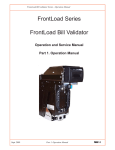
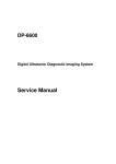
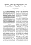
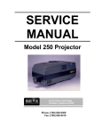
VCE-PRO
TM
User’s Manual
CONFIDENTIAL NOTICE:
Copyright ©2004, Imperx, Inc. All rights reserved.
Any unauthorized use, duplication or distribution of this document or any part thereof,
without the prior written consent of Imperx Corporation is strictly prohibited.
Imperx, inc.
6421 Congress Ave Ste. 204
Boca Raton, FL 33487 USA
DOC-0013-0002
Rev. RA03
08/15/05
CONFIDENTIAL & PROPRIETARY
Page 1 of 54
Revision History
RA01
RA02
RA03
Feb-04-2004
Feb-11-2004
June-27-2005
J. Egri
J. Egri
J. Egri
Initial Release to PDM system
Changed ‘Software Suite’ section
Updated software installation
instructions for new driver install.
Updated Chapter 4 with Auto Crop
feature to reflect v2.6 of application.
Page 2 of 54
Table Of Contents
CHAPTER 1 - INTRODUCTION..............................................................................................................................5
VCE-PRO ..................................................................................................................................................................6
WHAT YOU NEED TO GET STARTED ...........................................................................................................................11
INSPECTING THE VCE-PRO PACKAGE .....................................................................................................................12
CHAPTER 2 – HARDWARE INSTALLATION ...................................................................................................13
CHAPTER 3 – SOFTWARE INSTALLATION ....................................................................................................14
SOFTWARE SUITE .....................................................................................................................................................14
SOFTWARE INSTALLATION FROM CD .......................................................................................................................16
SOFTWARE UPGRADE FROM WEB SITE .....................................................................................................................21
FIRMWARE UPGRADE FROM WEB SITE .....................................................................................................................26
CHAPTER 4 – USING THE VCE-PRO..................................................................................................................27
RUNNING THE VCE-PRO APPLICATION ...................................................................................................................28
MAIN WINDOW ........................................................................................................................................................29
CONTROL PANEL ......................................................................................................................................................33
PLAYER CONTROL ....................................................................................................................................................45
PLAYER DIALOG .......................................................................................................................................................47
CHAPTER 5 – ELECTRICAL INTERFACES......................................................................................................48
VIDEO CONNECTOR ..................................................................................................................................................49
EXTERNAL TRIGGER CONNECTOR ............................................................................................................................51
PCMCIA/CARDBUS CONNECTOR ............................................................................................................................53
CHAPTER 6 - SPECIFICATIONS..........................................................................................................................54
Page 3 of 54
Illustrations
Figure 1 – VCE-PRO Block Diagram ...........................................................................................................................8
Figure 2 – EEPROM Programming In System............................................................................................................10
Figure 3 – VCE-PRO video – mating plug..................................................................................................................49
Figure 4 – VCE-PRO External Trigger – mating plug ................................................................................................51
Figure 5 – External trigger schematic..........................................................................................................................52
Tables
Table 1 – Video decoder pixel data ...............................................................................................................................9
Table 2 – VCE-PRO Image data mapping into memory ...............................................................................................9
Table 3 – VCE-PRO-F Connector Pin-out ..................................................................................................................50
Table 4 – Cardbus Connector Pin-out..........................................................................................................................53
Page 4 of 54
Chapter 1 - Introduction
Introduction
This chapter outlines the key features of the Imperx VCE-PRO card.
Page 5 of 54
VCE-PRO
The VCE-ANCB frame grabber is a TYPE II PC Card with both an analog
video interface and Cardbus interface. It provides the ability to capture
analog NTSC/PAL video data from either a CVBS or S-Video source and
transfer that data to host memory via a Cardbus ( PCI ) interface.
Functionality
•
Provides two composite or S-Video inputs.
•
Captures video data from standard NTSC, PAL or SECAM
analog sources, formats this data and stores it into local SDRAM.
•
Retrieves the formatted data from the SDRAM and transfers it into
host memory via scatter/gather DMA over the Cardbus.
•
Provides a hardware based scaler function which can scale the
image size to 100%, 50% , 25% or a user defined scaling factor.
Since the scaling is performed on the card, less Cardbus bandwidth
is required to transfer the image to host memory.
•
VCE-PRO is capable of saving images to disk as either BMP,
JPEG or AVI files.
•
Provides an internal triggering capability that can qualify image
capture based on time as specified by the user.
•
Provides an external triggering capability that can qualify image
capture based on external signals.
•
Automatically overlays the captured image with a date stamp, time
stamp or user text.
•
Provides adjustable image brightness, contrast, hue and saturation.
Interfaces
Analog interface
The VCE-PRO provides two CVBS ( composite ) or two S-Video inputs
using either a set of stereo phono-jacks ( model VCE-PRO ) or a 15 pin
connector ( model VCE-PRO-F ).
Page 6 of 54
PCMCIA/CardBus interface
The VCE-PRO card complies with the TYPE II PC Card package
dimensions as defined in the PC Card Release 8.0 Standard. The VCEPRO includes a 30mm x 10mm extension area, used to house the
stereo phono-jack connectors. The VCE-PRO-F version does not include
the extension area.
The VCE-PRO provides a 33 MHz 32 bit PCI Master/Target interface
( Cardbus ) compliant with the PC Card Release 8.0 specification. This
interface provides a single ‘function’, as defined in the Cardbus
specification. The design does not support any memory mapped or I/O
mapped peripherals on card. Access to the VCE-PRO’s SDRAM devices
is achieved through DMA operations that move the data from the SDRAM
into host memory. The host cannot directly access the contents of the
SDRAM. The design supports host access into configuration registers,
DMA registers, local registers and CIS data via configuration space
accesses.
Page 7 of 54
CardBus
Connector
68-pin Female
Figure 1 – VCE-PRO Block Diagram
Page 8 of 54
SoftStart
32-bit PCI
Master/Slave
SDRAM
4Mx32
BGA-90
Configuration
EEPROM
EPC2
FPGA
ACEX EP1K100
BGA-256
3V-to-2.5V
converter
SDRAM
4Mx32
BGA-90
OSC
66Mhz
8
8
i2c_SCL
i2c_SDA
Strobes 3
Clk
Y
Cr/Cb
ByteBlaster
Programming
Header
Video
Decoder
Philips
SAA7115
Trigger
Detector
C1
C0
CVBS1/Y1
CVBS0/Y0
Stereo
Phono-Jacks
( VCE-PRO
version )
OR
15 Pin
Connector
( VCE-PRO-F
version )
A functional block diagram of the VCE-PRO card is illustrated in
Figure 1.
Video Capture
The video capture engine is responsible for receiving video pixel data and
qualifiers from the on-board video decoder chip, formatting the data and
transferring it into on-board memory. The data that it receives from the
video decoder is 4:2:2 YCrCb data formatted per Table 1. The video
decoder delivers 8 bits of Luminance data ( Y ) and 8 bits of Chrominance
data ( Cr/Cb ).The video capture engine translates this data into longwords
( 32 bits ) as defined in Table 2. This format reflects how the data will
appear in host memory. The module packs two pixels into each longword
in order to use the Cardbus bandwidth more efficiently and conserve
memory space.
H-Port
I-Port
d15 d14 d13 d12 d11 d10 d9 d8 d7 d6 d5 d4 d3 d2 d1 d0
Cr/Cb ( chrominance )
Y ( luminance )
Table 1 – Video decoder pixel data
d31 d30 d29 d28 d27 d26 d25 d24 d23 d22 d21 d20 d19 d18 d17 d16 d15 d14 d13 d12 d11 d10 d9 d8 d7 d6 d5 d4 d3 d2 d1 d0
Cr/Cb-pixel2
Y-pixel2
Cr/Cb-pixel1
Y-pixel1
Table 2 – VCE-PRO Image data mapping into memory
Pixel Buffering
The pixel data formatted by the video capture engine is stored into two
on-board 4Mx32 SDRAM devices. This memory serves as a local store for
formatted video pixel data. Each SDRAM will buffer a single frame’s
worth of data, supporting a maximum frame size of 8 million pixels/frame.
The SDRAMs are managed by an independent pair of controllers,
implemented in the FPGA, supporting concurrent operation. The two
SDRAMs are utilized in a ping-pong fashion such that while one is being
filled with new pixel data, the other is being emptied via DMA into host
memory.
DMA
The DMA engine is responsible for reading formatted pixel data from the
on-board SDRAM devices and transferring them into host memory via the
Cardbus interface. An intelligent scatter-gather method is utilized,
providing for an efficient use of the Cardbus bandwidth. The use of noncontiguous 4Kbyte buffers provides support for the Windows operating
system’s memory allocation model.
Page 9 of 54
FPGA
The heart of the VCE-PRO is a dense Field Programmable Gate Array
( FPGA ). This FPGA implements all of the functions related to video
data capture, storage and DMA. The firmware contents of the FPGA can
be upgraded while in the field by following the instruction outlined in
Section 3 of this document entitled ‘Firmware Upgrade from Web Site’.
In System Programming:
The VCE-PRO design supports ISP programming during operation. This
capability is useful when the FPGA code needs to be upgraded and the
unit is at a remote customer location. The programming is accomplished
using a JamPlayer utility, which runs on the host PC. The JamPlayer
utility downloads a new FPGA image into the EEPROM via the Cardbus
interface. The FPGA provides a set of I/O pins which are connected to the
EEPROM’s JTAG interface. The JamPlayer utility toggles these I/O pins,
which are mapped into a register in configuration space, and thus can
communicate with the EEPROM’s JTAG controller and affect a
programming operation.
I/O
I/O
I/O
Cardbus
Interface
I/O
FPGA
TCK
TMS
TDI
Configuration
EEPROM
Cardbus
Connector
TCK
TMS
ISP
TDO
TDI
TDO
VCE-PRO Card
Figure 2 – EEPROM Programming In System
Page 10 of 54
Not
Used
PC
w/JamPlayer
What you need to get started
To begin using the VCE-PRO card, you need the following:
•
A computer with a PCMCIA slot that is Cardbus compliant.
•
Microsoft Windows XP or 2000 software.
•
A computer with a relatively up to date Cardbus-to-PCI chipset
( sometimes referred to as a ‘Cardbus Controller’ ). You can determine
which chipset your laptop uses by looking in:
Control Panel – System – Hardware – Device Manager – PCMCIA
Adapters
These chipsets are recommended because they generally offer better
performance in terms of DMA transfer rates:
TI PCI-1520
TI PCI-4510
These chipsets are discouraged because of their poor DMA
performance:
O2 Micro OZ6912
TI PCI-1225
•
A computer with at least 256M bytes of RAM.
•
A CD drive, and a hard disk on which to install the VCE-PRO
software.
Page 11 of 54
Inspecting the VCE-PRO package
When you unpack your VCE-PRO package, you should visually inspect
all of its contents. If something is missing or damaged, contact your
Imperx representative.
Package contents
You should have received the following items:
•
The VCE-PRO PCMCIA card
•
A phono-plug to S-Video cable ( VCE-PRO )
•
A 15-pin plug to S-Video cable ( VCE-PRO-F )
•
An S-Video to RCA cable
•
A CD with the VCE-PRO software suite
•
A ‘Quick Start’ installation guide
•
A ‘User’s Manual’ ( this document )
Page 12 of 54
Chapter 2 – Hardware Installation
Hardware Installation
Installing the VCE-PRO card is as simple as plugging it into an available
PCMCIA slot on your computer.
Page 13 of 54
Chapter 3 – Software Installation
Software Installation
This chapter explains how to install the VCE-PRO software.
Software Suite
The VCE-PRO software suite consists of the following files:
Windows 2000 and XP application files:
( located in c:\Program_Files\ImperX\VCE-Pro\ )
AMCap.exe
ijl20.dll
vceancb.chm
VCEANCB.exe
VCEANCB.dll
- DirectX sample application
- Intel JPEG encoding/decoding library
- VCE-PRO help file
- VCE-PRO main application
- VCE-PRO library
Windows 2000 and XP driver files:
( located in c:\Program_Files\ImperX\VCE-Pro\Drivers\WDM\ )
IpxInstDrv.exe
vceancb.sys
vceancb.inf
- Driver installer program
- VCE-PRO Win2000/XP driver file
- VCE-PRO Win2000/XP driver info file
WDM Streaming ( DirectX ) files:
( located in c:\Program_Files\ImperX\VCE-Pro\Drivers\DirectX\ )
install_ks.txt
instvcecbks.exe
IpxInstDrv.exe
VceAncbKs.ax
Vcecbks.inf
Vcecbks.sys
Vcecbsks.inf
- WDM Streaming installation instructions
- WDM Streaming installation program
- Driver installer program
- WDM Streaming driver’s properties plugin
- VCE-PRO WDM Streaming info file
- VCE-PRO WDM Streaming driver
- VCE-PRO WDM Streaming info file
Page 14 of 54
Documentation files:
( located in c:\Program_Files\ImperX\VCE-Pro\Doc\ )
VCE-PRO_Users_Manual.pdf - User manual document
VCE-PRO_Spec.pdf
- Technical datasheet
History_drv.txt
- WDM driver change description file
History_ks.txt
- KS driver change description file
History_app.txt
- Application change description file
Note that our VCE-PRO application program was created using our SDK
( software developers kit ). Our SDK is a separately purchased product
and is not included in the standard VCE-PRO software suite that comes
with the card. For more information on the SDK, please visit our web site
at http://www.imperx.com/sdk/index.php or call us toll free at 1-877-863-1654.
Page 15 of 54
Software Installation from CD
Use the following steps to install the VCE-PRO software supplied on a
CD:
1.
If a version of VCE-PRO was previously installed on this machine,
then you must first remove it:
To remove the application files:
1.1
1.2
1.3
1.4
1.5
1.6
1.7
1.8
1.9
2.
Left mouse click on “Start”
Left mouse click on “Settings”.
Left mouse click on “Control Panel”.
Double left mouse click on “Add or Remove Programs”.
Left mouse click on “Video Capture Essentials –
Professional’.
Left mouse click on “Remove”.
If the ‘VCE-PRO – InstallShield Wizard’ pops-up,
do the following:
If not, go to step 1.8
Left mouse click on ‘Remove’.
Click ‘Next’.
Click ‘Yes’.
Click ‘Finish’.
Left mouse click on “Yes”.
Left mouse click on “Close”.
After having removed a previous version or if a version of VCEPRO was NOT previously installed on this machine then:
The first step is to install the application files:
2.1
2.2
2.3
2.4
Insert the VCE-PRO CD into the appropriate drive; the
setup.exe file will run automatically. Note: If it does not
start automatically, left mouse click on to “Start”, “Run”,
enter or browse to “(CD drive): setup.exe” and click “OK”.
Wait for the “VCE-PRO - InstallShield Wizard” screen to
appear.
Follow the on-screen instructions.
For Windows XP, the following message will appear:
Page 16 of 54
For Windows 2000, the following message will appear:
2.5
2.6
Click “Continue Anyway” for XP, “Yes” for 2000.
When the following message appears, choose if you
would like to register online by left clicking on “Yes”
or “No”.
If you choose “Yes”, follow the on-screen instructions.
Page 17 of 54
2.7
When prompted, select ”Yes, I will restart my
computer now”.
After restarting the computer a New Hardware Found screen
will come up: ( the VCE-PRO card must be installed to
perform the following steps )
Steps 2.8 through 2.14 are for Windows XP. For Windows 2000,
go to Step 2.15
2.8
2.9
Wait for the system to prompt you with a “Found
New Hardware Wizard” dialog box.
Under certain conditions, the following message
may appear:
If this message appears, click “No, not this time”, then
“Next”.
Page 18 of 54
2.10
When the following message appears, select “Install
the software automatically (Recommended)”, then left
click “Next”.
2.11
For Windows XP, the following message will appear:
2.12
2.13
Click “Continue Anyway” to continue.
When “Click Finish to close the wizard” appears, Left
click on “Finish”.
This completes the installation for Windows XP.
2.14
To install the WDM driver for Windows 2000:
2.15
Wait for the system to prompt you with a “Found New
Hardware Wizard” dialog box.
Page 19 of 54
2.16
Left click “Next” to continue. The following message will
appear:
Click “Yes” to continue.
2.17
2.18
2.19
Click “OK”, then either enter or browse to:
C:\Program Files\ImperX\VCE-Pro\Drivers\WDM
Click “OK”.
This completes the installation for Windows 2000.
Page 20 of 54
Software Upgrade from Web Site
New application and/or driver software may be released periodically to
reflect improvements and/or functionality added to the VCE-PRO. You
can retrieve these updates by visiting the download page of our web
site at
http://www.imperx.com/frame_grabbers/pcmcia_analog/vce-pro-downloads.php
Use the following steps to install newly released application software:
3.1
3.2
3.3
3.4
3.5
3.6
Uninstall all application files by following the instructions in
step 1. of the ‘Software Installation from CD’ section.
Download the VCE-PRO_Installer.exe file from the Imperx
web site to a new folder on your PC ( we will use the folder
C:\new_VCE-PRO as an example ).
Left mouse click on “Start”, “Run”, enter or browse to
“C:\new_VCE-PRO\VCE-PRO_Installer.exe”.
Left mouse click on “Open”, then “OK”.
Follow the on-screen instructions.
For XP, when the following message appears, left click
“Continue Anyway”
Page 21 of 54
For Windows 2000, when the following message
appears, click “Yes”.
3.7
When the following message appears, choose if you
would like to register online by left clicking on “Yes”
or “No”.
If you choose “Yes”, follow the on-screen instructions.
3.8
4.
When prompted, select ”Yes, I want to restart my
computer now” and left click “Finish”.
After having successfully installed the newly released application
software, use the following steps to install a newly released WDM
driver for Windows XP ( for Windows 2000 go to step 5. ):
4.1 Wait for the system to prompt you with a “New Hardware
Found” dialog box.
4.2 Under certain conditions, the following message
may appear:
Page 22 of 54
If this message appears, click “No, not this time”, then
“Next”.
4.3 When the following message appears, select “Install the
software automatically (Recommended)”, then left click
“Next”.
4.4
For XP, when the following message appears, left click
“Continue Anyway”.
Page 23 of 54
4.5
4.6
5.
When “Click Finish to close the wizard” appears, Left click
on “Finish”.
This completes the installation for Windows XP.
After having successfully installed the newly released application
software, use the following steps to install a newly released WDM
driver for Windows 2000:
5.1
Wait for the system to prompt you with a “Found New
Hardware Wizard” dialog box.
5.2
Left click “Next” to continue. The following message will
appear:
Page 24 of 54
5.3
Click “Yes” to continue.
5.4
Click “OK” , then either enter or browse to:
C:\Program Files\ImperX\VCE-Pro\Drivers\WDM
Click “OK”.
This completes the installation for Windows 2000.
5.5
5.6
Page 25 of 54
Firmware Upgrade from Web Site
Your newly received VCE-PRO card has been programmed in the factory
with the latest firmware prior to shipping. New firmware, however, may
be released periodically to reflect improvements and/or functionality
added to the VCE-PRO FPGA. You can retrieve these updates by visiting
the download page of our web site at
http://www.imperx.com/frame_grabbers/pcmcia_analog/vce-pro-downloads.php
Use the following steps to install newly released firmware:
1.
Download and unzip the firmware patch ( .zip ) file to a folder on
your PC ( we will use C:\fw_patch as an example ).
2.
If you haven't previously installed the JamPCI drivers then:
2.1
Left mouse click on to “Start”, “Run”, enter
“C:/fw_patch/loadsys.bat” and click ”OK”.
2.2
Wait until "Press any key to continue . . ." message appears.
2.3
Press any key to exit batch file.
3.
Insert the VCE-PRO card into the laptop. Note that if your system
has two PCMCIA slots, then you must insert the card into the slot
in which it was placed during the original driver installation.
4.
If the system prompts you with a “New Hardware Found” dialog
box, press “Cancel”.
5.
Note: DO NOT POWER DOWN OR REMOVE CARD
WHILE PROGRAMMING IS IN PROGRESS!
6.
Left mouse click on “Start”, “Run”, enter
“C:/fw_patch/VCE-PRO_patch_x_y.bat” and click ”OK”.
Note that ‘x_y’ refers to the revision number ( i.e. 2.0 ).
7.
Wait until "Press any key to continue . . ." message appears.
8.
If line above it reads "Exit code = 0...Success" then proceed with
installation, otherwise contact [email protected].
9.
Press any key to exit batch file.
10.
You must either reboot the PC or remove and then reinsert the
VCE-PRO card in order for the changes to take effect
Page 26 of 54
Chapter 4 – Using the VCE-PRO
Using the VCE-PRO
This chapter contains information on how to configure and use the
VCE-PRO card.
Page 27 of 54
Running the VCE-PRO Application
The VCEANCB.exe program supplied with the VCE-PRO card is a
stand-alone Windows based application. It provides an easy to use
graphical user interface ( GUI ), allowing the user to configure the
VCE-PRO card and to view, record and playback video data received
from the analog interfaces. The application consists of a main window as
well as ‘Control Panel’, ‘Player Control’ and ‘Player Dialog’ windows.
Launching
Application
To launch the VCE-PRO application, simply double left mouse click on
the ‘VCE-PRO application’ icon on the desktop.
Note
In the remainder of this chapter, references to ‘clicking’ on objects in the
GUI refers to the left mouse button.
Page 28 of 54
Main Window
When the VCEANCB.exe program is executed, a main window titled
‘ImperX VCE-PRO’ will appear. The main window provides the primary
area for viewing real-time images received from the camera. This window
can be sized and moved to suit your needs. When image viewing is active,
the size of this window will automatically be scaled as a function of the
incoming video signal ( i.e. NTSC or PAL ).
File
Clicking on this item reveals a pull-down menu with two options:
‘Player’ and ‘Exit’.
Player
This option opens the ‘Player Dialog’ and ‘Player Control’
windows.
Exit
Clicking on this option causes the program to terminate.
Grabber
Refresh
Clicking on this item reveals a pull-down menu with a ‘Refresh’ option
and a list of PCMCIA slots populated with VCE-PRO cards.
Clicking on this option causes the program to search all slots and
update the list of installed VCE-PRO cards.
Page 29 of 54
Slot List
Camera
If a single VCE-PRO is installed, then only ‘Slot #0’ will appear. If
two VCE-PRO cards are installed, then both ‘Slot #0’ and ‘Slot #1’
will appear. The user can select which card is to be active by
clicking on the appropriate slot number.
Clicking on this item reveals a pull-down menu with the following
options:
Interlace
Select this item if the video source is interlaced.
Composite1
Select this item if the video source is a composite signal and is
connected to channel #1.
Composite2
Select this item if the video source is a composite signal and is
connected to channel #2.
S-Video1
Select this item if the video source is an S-Video signal and is
connected to input #1.
S-Video2
Select this item if the video source is an S-Video signal and is
connected to input #2.
Input Window
Select this item to reveal the ‘Input acquistion window’ dialog.
This dialog allow the user to adjust the VCE-PRO’s video
acquisition parameters to agree with that of the attached video
source. Some video sources produce extra black columns or rows
that the user may wish to remove from the image. There are two
ways to remove these extraneous pixels: manually using the ‘Input
window definition’ parameters or automatically using the ‘Auto
Crop’ feature.
Page 30 of 54
Input window definition: Allows you to manually crop the image.
xOffset
This field allows you to define the starting horizontal pixel
in each row and thereby delete any leading ( left most )
columns in the image.
xActive
This field allows you to define the number of pixels in each
row to be displayed starting from the pixel defined in
xOffset and thereby delete any trailing ( right most )
columns in the image.
yOffset
This field allows you to define the starting vertical row and
thereby delete any leading ( top most ) rows in the image.
yActive
This field allows you to define the number of rows to be
displayed starting from the row defined in yOffset and
thereby delete any trailing ( bottom most ) rows in the
image.
Preview
Click on this button to see a preview of the image resulting
from changing the above parameters.
Default
Click this button to revert back to the default settings.
Auto Crop: An algorithm performed by the VCE-PRO software that scans an
image from left-to-right, right-to-left, top-to-bottom and bottom-totop looking for a transition in the pixel intensity from black to a
threshold value. It will then note the number of black pixels and
adjust the xOffset, xActive, yOffset and yActive parameters
accordingly.
Threshold
This field allows you to define the threshold value to be
used by the Auto Crop algorithm.
AutoCrop
Click on this button to execute the Auto Crop algorithm.
OK
Click on this button to accept the changes and close this dialog.
Cancel
Click on this button to ignore the changes and close this dialog.
Page 31 of 54
Control Panel
Clicking on this item reveals a pull-down menu with the following
options:
Show panel
Selecting this item causes the ‘Control Panel’ dialog to appear.
When the ‘Control Panel’ dialog is open, the ‘Show panel’ menu
item changes to ‘Hide panel’. Clicking on ‘Hide panel’ causes the
‘Control Panel’ dialog to close. Alternatively, you can enter
<Ctrl-P> to open or close the ‘Control Panel’ dialog.
Zoom
Reveals a pull-down menu which allow the user to select the image
scaling factor. The image scaling factor determines the size of the
display window and the captured image. Changing from one scale
to another scale automatically updates the display window and
image size.
Help
Clicking on this item reveals a pull-down menu with two options:
‘About’ and ‘Help Manual’.
About
Clicking on this option causes version information to be displayed
including release identifiers for the application software, library,
driver and firmware. This information should be provided to
Imperx technical support personnel during a service call.
Help
Manual
Clicking on this option causes an interactive point-and- click
style help manual to be displayed. The help manual provides a
summary description of all GUI controls and fields.
Page 32 of 54
Control Panel
This dialog is invoked by clicking on ‘Show panel’ under the ‘Control
Panel’ item in the top level menu. The Control Panel dialog allows the
user to program the operating parameters of the VCE-PRO card and gives
the user complete control over image viewing and storage. The window
can be moved anywhere around the screen to suit your needs.
Page 33 of 54
Image
Control
These sliders allow the user to control the brightness, contrast, hue and
saturation of the image. ‘Reset’ causes all sliders to revert back to their
default settings.
Brightness Moving the slider up increases brightness causing more white
while moving it down decreases brightness causing less white.
Contrast
Moving the slider up increases contrast causing greater differences
between dark and light while moving the slider down decreases
contrast causing fewer differences between dark and light.
Hue
Moving the slider up increases hue causing an increase in the
intensity of Red and Yellow while moving the slider down causes
an increase in the intensity of Blue and Green.
Saturation
Moving the slider up increases saturation causing white to be
removed from the colors while moving the slider down decreases
saturation causing white to be added to the colors.
Input Color
Carrier Level
This selection informs the VCE-PRO of the strength on the incoming
color signal. If the input signal’s strength is low ( due to a worn VCR head
or excessive cabling ) then set this field to ‘Low’ otherwise set it to
‘Normal’.
Color Settings
Specifies the video mode as either monochrome or color.
Image Format
When recording images to disk, this option selects the format, ‘BMP’ or
‘JPEG’, that the image will be saved in. Selecting ‘JPEG’ activates a
compression slider. ‘Best Quality’ provides the least compression while
‘Smallest File’ provides the most compression.
Image Size
Determines the size of the display window and the captured image.
Changing from one scale to another scale automatically updates the
display window and image size. Selecting ‘Custom’ causes another dialog
box to pop-up with fields that allow the user to specify an arbitrary width
and height for the image.
Capture Options
Determines how, when and where images are recorded to disk. Three
choices are provided: ‘Single Frames’, ‘Series of Frames’ and ‘AVI
Video’. Clicking on each option opens a new dialog window providing
additional options.
Single Frames
Select this option when you wish to record one frame only.
Clicking on this button causes the ‘Single Frame Settings’
dialog window to open.
Page 34 of 54
Path/Filename
This text field allows you to provide a path and
filename for the recorded image file. Clicking on
the ‘…’ box will cause a Windows ‘browse’ box to
appear. The user can then browse to a folder and
enter a file name. The filename extension, .BMP or
.JPG, will automatically be added depending on the
image format chosen and therefore you do not need
to include the filename extension.
Text Overlay
Enabling ‘Insert Date and Time’ automatically
places the date and time on each image recorded.
Date and time formats are the same as those used on
your computer. Enabling ‘Insert Text Message’
allows you to enter a text string to be automatically
overlayed on each image recorded. Clicking on
‘Position’ causes a pull-down menu to appear
which defines the placement position of the
date/time/text message within the image. Available
options include: Top-Left, Top-Center, Top-Right,
Bottom-Left, Bottom-Center and Bottom-Right.
Accept
Clicking on this causes the entries made to the
various fields to be accepted and then closes the
‘Single Frame Settings’ dialog window.
Cancel
Clicking on this causes the entries made to the
various fields to be rejected and then closes the
‘Single Frame Settings’ dialog window.
Page 35 of 54
Series of Frames Select this option when you wish to record multiple frames.
Clicking on this button causes the ‘Series of Frames Settings’
dialog window to open.
Path/Filename
This text field allows you to provide a path to a
folder where the recorded image files will be saved
to. Clicking on the ‘…’ box will cause a Windows
‘browse’ box to appear. The user can then browse to
a folder. The filename will automatically be created
based on the choice made in the ‘Append to
filename’ option. The filename extension, .BMP or
.JPG, will automatically be added depending on the
image format chosen.
Page 36 of 54
Append to
filename
Allows the user to choose the format of the text
filename to be created. Every time a recording file
is created, the filename suffix will automatically be
updated ( for the ‘Date and Time’ option ) or
incremented ( for the ‘N Digit Number’ option ).
Date and Time
This option will create files named as
YYYYMMDDhhmmssnnn where:
Y - year (4 digits)
M - month (2 digits)
D - day (2 digits)
h - hour (2 digits)
m - minute (2 digits)
s - second (2 digits)
n - millisecond (3 digits)
‘N’ Digit Number
This option will create numerically named
files. The filename starts at 0 and is
incremented by one after each frame is
captured. If the number of frames captured
exceeds the number of digits selected then
the filename will continue to increment.
For example:
If ‘2 Digit Number’ is selected then the files
will be named as:
‘00.bmp’, ‘01.bmp’ … ‘99.bmp’,
‘100.bmp’, ‘101.bmp’, etc.
If ‘4 Digit Number’ is selected then the files
will be named as:
‘0000.bmp’, ‘0001.bmp’ … ‘9999.bmp’,
‘10000.bmp’, ‘10001.bmp’, etc.
Capture every
Allows you to control how often an image is
captured. Use this feature to take snapshots at
regular intervals in order to create a time-lapse
series of images.
Capture at
Allows you to control the rate at which frames are
captured in terms of frames per second.
Limit capture
time to
Allows you to limit the duration of the recording by
the amount of time specified. This option is
Page 37 of 54
mutually exclusive with the ‘Limit number of frame
to’ option.
Limit number
of frames to
Allows you to limit the duration of the recording by
the number of frames specified. This option is
mutually exclusive with the ‘Limit capture time to’
option.
Freeze preview
window while
capturing
When selected will stop the live image in the main
window from updating during capture, otherwise
the image will remain live. Selecting this option
improves capture performance ( i.e. the number of
frames per second stored to disk ).
Text Overlay
Same as in ‘Single Frames’.
Accept
Same as in ‘Single Frames’.
Cancel
Same as in ‘Single Frames’.
Page 38 of 54
AVI Video
Select this option when you wish to create an AVI movie file. An
AVI movie is a series of BMP files assembled into a single AVI
file. This choice is not available if JPEG was chosen as the ‘Image
Format’. Clicking on this button causes the ‘AVI Video Clip
Settings’ dialog window to open.
Path/Filename
Same as in ‘Single Frames’.
Capture [ ]
Frames per
Second
Limits the frame rate of the recorded movie.
Compression
Allows you to choose between a variety of
compressor implementations and options. Clicking
on this button causes the ‘Video Compression’
dialog window to open.
Page 39 of 54
Compressor
This pull-down menu lists several different
implementations of AVI compressors. Each
has its own set of configuration options.
Compression
Quality
Lets you trade off quality versus file size.
The higher the quality, the larger the file
size and the lower the quality, the smaller
the file size.
OK
Clicking on this causes the entries made to
the various fields to be accepted and then
closes the ‘Video Compression’ dialog
window.
Cancel
Clicking on this causes the entries made to
the various fields to be rejected and then
closes the ‘Video Compression’ dialog
window.
Configure…
Provides additional configuration options
that are specific to the type of compressor
chosen.
About…
Provides version number information for the
chosen compressor.
Limit number
of frames to
Allows you to limit the duration of the recording by
the number of frames specified.
Use trigger
Allows you to specify the external trigger as the
event which controls AVI recording.
Trigger behavior
Same as ‘External Trigger Settings’.
Page 40 of 54
Freeze preview
window while
capturing
Same as in ‘Series of Frames’.
Limit number
of frames to
Allows you to limit the duration of the recording by
the number of frames specified.
Text Overlay
Same as in ‘Single Frames’.
Accept
Same as in ‘Single Frames’.
Cancel
Same as in ‘Single Frames’.
Page 41 of 54
External Trigger
Settings
Select this option when you want the recording process to be
controlled by the state of the ‘external trigger’ input.
Path/Filename
Same as in ‘Series of Frames’.
Append to
filename
Same as in ‘Series of Frames’.
Capture every
Same as in ‘Series of Frames’.
Trigger
behavior
This drop-down box allows the user to specify the
conditions, of the external trigger, necessary to start
image capture. Note that all triggers work in
conjunction with ‘Limit capture time to:’ and ‘Limit
Page 42 of 54
number of frames to:’. If you do not want these
settings to affect the trigger then set them to zero.
Trigger
while high
Start capturing images when the trigger is
high ( voltage present ) and continue
capturing images until the trigger goes low
( voltage absent ).
Trigger
while low
Start capturing images when the trigger is
low ( voltage absent ) and continue
capturing images until the trigger goes high
( voltage present ).
Trigger on
rising edge
Start capturing images when the trigger goes
from low ( voltage absent ) to high ( voltage
present ).
Trigger on
falling edge
Start capturing images when the trigger goes
from high ( voltage present ) to low
( voltage absent ).
Limit capture
time to
Same as in ‘Series of Frames’.
Limit number
of frames to
Same as in ‘Series of Frames’.
Save all frames
to same folder
Causes frames captured as a result of multiple
trigger events to be saved to the same folder. If this
is not selected, then a new folder will automatically
be created with each trigger event.
Freeze preview
window while
capturing
Same as in ‘Series of Frames’.
Text Overlay
Same as in ‘Series of Frames’.
Accept
Same as in ‘Series of Frames’.
Cancel
Same as in ‘Series of Frames’.
Page 43 of 54
Start/Stop
Grab
This button will toggle between ‘Start Grab’ and ‘Stop Grab’ every time
the user clicks on it. Clicking on ‘Start Grab ‘enables the VCE-PRO’s
DMA engine and causes the main window to display live images received
from the camera. Clicking on ‘Stop Grab’ disables the DMA engine and
causes the display to freeze.
Start/Stop
Capture
This button will toggle between ‘Start Capture’ and ‘Stop Capture’
every time the user clicks on it. Clicking on ‘Start Capture‘ starts the
process of recording the images to disk. The options set in the ‘Capture
Options’ field determine what, how and when actual recording is
performed. Clicking on ‘Stop Capture’ causes recording to stop.
Hide
Clicking on this option causes the control panel dialog to close. To reopen,
click on ‘Control Panel’ and ‘Show panel’ in the top level menu of the
main window.
Page 44 of 54
Player Control
Clicking on the ‘Player’ item under the ‘File’ pull-down menu at the top
of the VCE-PRO main window causes two windows to appear: ‘Player
Control’ and ‘Player Dialog’. These windows can be moved anywhere
around the screen to suit your needs.
The Player Control window is used to select the pre-recorded image(s)
that you wish to view. Note that support for AVI playback has been
removed from the VCE-PRO. Instead, use Windows Media Player to view
AVI movies.
Image Size
Determines the size of the Player Dialog window and the playback image.
Changing from one scale to another automatically updates the Player
Dialog window and image size.
Path
This text field allows you to enter the name of the folder or directory
containing the image file(s). Clicking on the ‘…’ box will cause a
Windows ‘browse’ box to appear.
Files
This box lists all of the image files ( either .BMP or .JPG ) that are in the
folder selected under ‘Path’. Note that .AVI files are not listed.
Page 45 of 54
Rewind
Displays a series of images ( one after another ), in rapid reverse order,
starting from the currently selected file, in the Player Control window’s
list, to the first file in the list.
Step
Backwards
Displays the previous image ( file ) in the list.
Play
Displays a series of images ( one after another ) starting from the currently
selected file in the list.
Step
Forward
Displays the next image ( file ) in the list.
Fast
Forward
Displays a series of images ( one after another ), in rapid forward order,
starting from the currently selected file to the last file in the list.
Stop
Halts current playback.
Page 46 of 54
Player Dialog
The Player Dialog window appears when the user selects the ‘Player’ item
under the ‘File’ pull-down menu at the top of the VCE-PRO main
window. The Player Dialog window provides the primary area for
viewing playback of pre-recorded images. This window can be moved
anywhere around the screen to suit your needs. The size of the window
( and image ) is determined by the size of the image file selected in the
‘Player Control’ window and can be scaled using the ‘Image Size’ option.
For example, if the user selects an image file that was produced by a
NTSC camera, then the ‘Full frame’ window size will be 640x480. In
this example, selecting ‘½ frame’ produces a window size of 320x240 and
selecting ‘¼ frame’ produces a size of 160x120.
Close
Closes the ‘Player Control’ and ‘Player Dialog’ windows.
Page 47 of 54
Chapter 5 – Electrical Interfaces
Electrical Interfaces
This chapter contains information on the VCE-PRO’s connectors.
Page 48 of 54
Video Connector
There are two versions of the VCE-PRO: the VCE-PRO, which utilizes
stereo phono jacks and the VCE-PRO-F which utilizes a 15 pin i/o
connector.
VCE-PRO
The analog video interface for the VCE-PRO card consists of two 2.5mm
stereo phono-jacks ( one per video channel ). The pin-out for the mating
phono plug is illustrated in Figure 3. Each phone jack provides three
signals:
CVBS/Y
- A composite signal or the luminance component of an
S-Video signal.
C
- A chrominance component of an S-Video signal.
Chassis GND - A shield/ground signal.
2.5mm Stereo Plug
C - Connects to pin 2 of the Jack
CVBS/Y - Connects to pin 3 of the Jack
GND - Connects to pin 1 of the Jack
Figure 3 – VCE-PRO video – mating plug
Page 49 of 54
VCE-PRO-F
The analog video interface for the VCE-PRO-F is a surface mount, right
angle, 15 position, female connector. The pins are used for analog video
and trigger inputs as indicated in Table 3.
Pin #
1
2
3
4
5
6
7
8
9
10
11
12
13
14
15
Signal
ANALOG GND
ANALOG GND
CVBS0/Y0
ANALOG GND
ANALOG GND
CVBS1/Y1
ANALOG GND
ANALOG GND
C0
ANALOG GND
C1
DIGITAL GND
Trigger_In +
Trigger_In DIGITAL GND
Table 3 – VCE-PRO-F Connector Pin-out
Page 50 of 54
External Trigger Connector
VCE-PRO
The external trigger for the VCE-PRO card consists of a 3.5mm female
stereo phono jack. The pin-out for the mating phono plug is illustrated
below.
3.5mm Stereo Plug
Trigger_In Connects to pin 2 of the Jack
Trigger_In +
Connects to pin 3 of the Jack
Not used
Figure 4 – VCE-PRO External Trigger – mating plug
VCE-PRO-F
The external trigger of the VCE-PRO-F card utilizes pins on the 15 pin
connector. Pins 13 and 14 are used for the Trigger_In + and Trigger_In –
signals, respectively.
Functionality
If external triggering is enabled, the VCE-PRO will use the state of the
external trigger signal to qualify when to start ( and optionally end )
capturing video images to disk. The VCE-PRO will wait until the trigger
condition ( as specified in the ‘Trigger behavior’ field of the ‘Trigger
Capture Settings’ dialog ) has been satisfied before beginning to store
video images to the disk. It will stop storing video images on the disk
when the programmed end condition has been met. The following external
trigger conditions can be specified:
Rising Edge
Image capture begins when a ‘logic-0’ to ‘logic-1’ transition
occurs on the trigger inputs.
Image capture ends when ‘limit number of frames to’ or ‘limit time
to’ has been met.
Page 51 of 54
Falling Edge
Image capture begins when a ‘logic-1’ to ‘logic-0’ transition
occurs on the trigger inputs.
Image capture ends when ‘limit number of frames to’ or ‘limit time
to’ has been met.
While High
Image capture begins when a ‘logic-1’ signal is present on the
trigger inputs.
Image capture ends when ‘logic-1’ to ‘logic-0’ transition occurs on
the trigger inputs.
While Low
Image capture begins when a ‘logic-0’ signal is present on the
trigger inputs.
Image capture ends when ‘logic-0’ to ‘logic-1’ transition occurs on
the trigger inputs.
Electrical
Considerations
The external trigger input is optically isolated from the rest of the VCEPRO hardware. An internal 300 ohm series resistor is used to limit the
input current. The input signals “TRIGGER IN +” and “TRIGGER IN -”
are used to connect to an external trigger source.
A ‘logic-0’ is considered a positive voltage ( between TRIGGER_IN +
and TRIGGER_IN - ) of 0v to 1.0v.
A ‘logic-1’ is considered a positive voltage ( between TRIGGER_IN +
and TRIGGER_IN - ) of 4.0v to 5.0v.
+3.3V
+3.3V
TRIGGER_IN +
2
1
TRIGGER_IN -
stereo phono jack
5
U13
R63 300
1
4
ANO COL
2
3
2 IN
OUT
BAS16LT1
1
CAT EMT
HMHAA280
OE
3
3
4
GND
D1
J8
C133
0.1uF
R64
10K
VCC
C134 0.1uF
VIDEO_TRIGGER_L
U12
NC7SZ125
R65
100
Figure 5 – External trigger schematic
CAUTION NOTE
The maximum input current MUST NOT exceed 10mA or else damage may
occur to the card!
Page 52 of 54
PCMCIA/Cardbus Connector
The Cardbus connector is a surface mount, right angle, 68 position, female
connector.
Pin #
1
2
3
4
5
6
7
8
9
10
11
12
13
14
15
16
17
18
19
20
21
22
23
24
25
26
27
28
29
30
31
32
33
34
Signal
GND
ad0
ad1
ad3
ad5
ad7
C/be0#
ad9
ad11
ad12
ad14
C/be1#
par
perr#
gnt#
int#
VCC
VPP1
clk
irdy#
c/be2#
ad18
ad20
ad21
ad22
ad23
ad24
ad25
ad26
ad27
ad29
rfu
clkrun#
GND
Pin #
35
36
37
38
39
40
41
42
43
44
45
46
47
48
49
50
51
52
53
54
55
56
57
58
59
60
61
62
63
64
65
66
67
68
Signal
GND
cd1#
ad2
ad4
ad6
rfu
ad8
ad10
vs1
ad13
ad15
ad16
rfu
block#
stop#
devsel#
VCC
VPP2
trdy#
frame#
ad17
ad19
vs2
rst
serr#
req#
c/be3#
audio#
stschg
ad28
ad30
ad31
cd2#
GND
Table 4 – Cardbus Connector Pin-out
Page 53 of 54
Chapter 6 - Specifications
Specifications
Video
Source
NTSC/PAL/SECAM
External
Trigger
Vlomin = 0.0V
Vlomax = 1.0V
Vhimin = 4.0V
Vhimax = 6.0V
Vrmax = 5.0V
Imin
= 5.0mA
Imax = 10.0mA
Physical
Dimensions
VCE-PRO :
PCMCIA Type II: 115.6mm(4.55in) x 54mm(2.1in) x 5mm(.2in)
with a 30mm x 10mm extension.
minimum forward voltage for logic-0
maximum forward voltage for logic-0
minimum forward voltage for logic-1
maximum forward voltage for logic-1
maximum reverse voltage
minimum current
maximum current...MUST NOT BE EXCEEDED!
VCE-PRO-F:
PCMCIA Type II: 115.6mm(4.55in) x 54mm(2.1in) x 5mm(.2in)
Weight
35 grams (1.25 oz)
Electrical
Characteristics
Operating voltage:
Operating current:
Inrush current:
Operating
Environment
Operating temperature: 0°C to 65°C
Relative humidity:
90% non-condensing
3.3V +/- 5%
160mA
360mA
Page 54 of 54