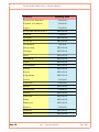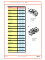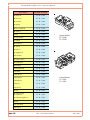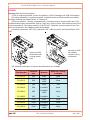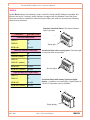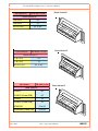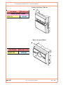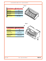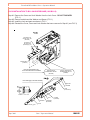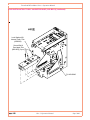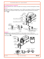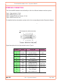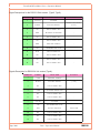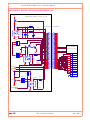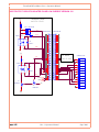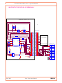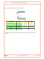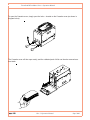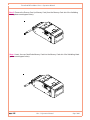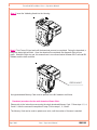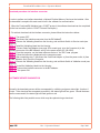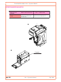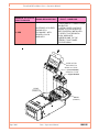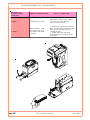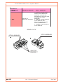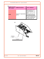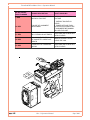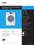
1
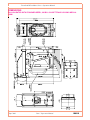
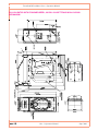
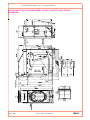
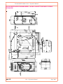
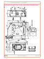
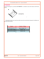
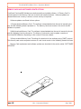
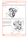
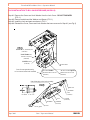
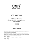
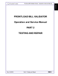
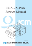
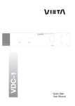
FrontLoad Bill validator Series - Operation Manual
FrontLoad Series
FrontLoad Bill Validator
Operation and Service Manual
Part 1. Operation Manual
Sept. 2009
Part 1. Operation Manual
PAGE 1-1
FrontLoad Bill validator Series - Operation Manual
Table of Contents
INTRODUCTION ............................................................................................................... 1-3
PRODUCT OVERVIEW .................................................................................................... 1-4
GENERAL SPECIFICATIONS .......................................................................................... 1-7
DIMENSIONS .................................................................................................................... 1-9
GENERAL WIRING DIAGRAM ...................................................................................... 1-15
MODULAR SYSTEM ...................................................................................................... 1-16
CHOOSING PART NUMBERS FOR THE BILL VALIDATOR ........................................ 1-31
INSTALLATION............................................................................................................... 1-32
INTERFACE CONNECTION ........................................................................................... 1-38
SWITCH SETTINGS ....................................................................................................... 1-44
MAINTENANCE & SERVICE.......................................................................................... 1-47
SOFTWARE UPDATES .................................................................................................. 1-49
TROUBLESHOOTING .................................................................................................... 1-53
TECHNICAL SUPPORT ................................................................................................. 1-61
page 1-2
Part 1. Operation Manual
Sept. 2009
FrontLoad Bill validator Series - Operation Manual
INTRODUCTION
The scope of this document is to provide full and clear information about the FL/MFL series of
CashCode bill validators.
This documents will be useful for those whose needs are:
- Development of new equipment with FL/MFL bill validators;
- Choice of the part number for the FL/MFL bill validator;
- Installation of the FL/MFL bill validator;
- Maintenance and service for the FL/MFL bill validator;
- Repair of the FL/MFL bill validator.
Sept. 2009
Part 1. Operation Manual
PAGE 1-3
FrontLoad Bill validator Series - Operation Manual
PRODUCT OVERVIEW
CashCode’s FrontLoad bill validator was developed to validate a wide variety of currencies. The
unit’s modular design provides extreme flexibility, allowing you to customize the bill validator to suit
your individual requirements.
The CashCode FrontLoad bill validator provides front access to a lockable cassette.
page 1-4
Part 1. Operation Manual
Sept. 2009
FrontLoad Bill validator Series - Operation Manual
The FrontLoad bill validator consists of six main modules. Each module is available in different
variations, to suit your needs. The picture below illustrates the different modules.
Memory Card (for software update)
Validating Head
Bezel (CashCode Standard Bezel is shown)
Housing (for 600 Cassette
with Lock Bracket is shown)
Power Interface Module
Cassette (600 bills cassette is shown)
Sept. 2009
Part 1. Operation Manual
PAGE 1-5
FrontLoad Bill validator Series - Operation Manual
The FrontLoad bill validator is designed accommodate bills 62 to 82 mm wide and 125 to 172 mm
llong – which encompasses most currencies.
Certain currencies have varying widths for diferent denominations. For proper handling of such
currencies, the Validating Head with a centering mechanism should be used. For currencies with
fixed-width, a fixed width Validating Head can be used.
Replaceable “Sense-a-Click™” sensor pak modules validate a specific currency, depending on the
type of sensor pak. The Power Interface module offers different interface options. The lockableremovable Cassette is used for temporary storage of validated bills. It can be locked with two
standard ¾” tubular locks . The Cassette is available in two sizes: 600 or 1000 bill capacity.
Sense-a-Click
(upper)
Sense-a-Click
(lower)
The Validating Head carries a set of Sense-a-Click™ sensor pak modules
Bill Capacity (600 or 1000 bills) refers to the amount of new bills that the Cassette can store. This
capacity however gets reduced when street grade bills are stored, due to their greater space requirement. The Housing joins all the other modules. Housing is permanently secured inside a Gaming
or Vending machine. There may be a mechanism for locking the Cassette within the Housing (Lock
Bracket), or there may be a Plain Bracket. The Housing also contains security switches, which
detect Cassette removal. Several Bezel styles are available for the FrontLoad. Software updates can
be easily completed with a Memory Card.
This modular design of the FrontLoad validator allows for replacement of failed modules in the field –
in just seconds!
page 1-6
Part 1. Operation Manual
Sept. 2009
FrontLoad Bill validator Series - Operation Manual
GENERAL SPECIFICATIONS
Acceptance:
Bills............................................................................................................lengthwise 4 ways
Barcoded Coupons.....................................................................................two ways, face up
Validation rate..........................................................................96% or higher on first insertion
Width of bill, in mm............................................................................................from 62 to 82
Maximum length of bill, in mm...........................................................................................172
Minimum length of bill, in mm............................................................................................124
Bill escrow...................................................................................................................one bill
Barcoded Coupon specifications:
Encoding standard................................................ANSI/AIM BC2-1995, Uniform Symbology
Specification - Interleaved 2 of 5
Narrow bar width, in mm..........................................................................................0.5 to 0.6
Wide/Narrow Bar Ratio .....................................................................................................3:1
Number of characters..................................................................................................6 to 18
PCS Value (Print Contrast Signal)..............................................................................0.6 min
Time of identificaion, in seconds....................................................................................2.5
(from time of bill insertion to time that credit is issued, in seconds)
Full validation time, in seconds:
Multi-width rontLoad...........................................................................................................4.5
FrontLoad...........................................................................................................................3.5
External interface:
a. Serial Interface, Opto-Isolated.
b. Serial Interface, RS 232C.
c. Isolated Pulse Low Current.
Smart Card (for bill validator with a Smart Card bezel):
Smart Card standard...............................................EMV2000L1 and/or ISO 7816 compatible
Number of supporting payment systems..............................................up to 4 simultaneously
Maximum stacking capacity of new bills in Cassette........................................600 or 1000
Power supply voltage*.............................................................................12 V.D.C. ± 1.0 V
.
or 24 V.D.C. ± 4.0 V
Current consumption*:
Operating mode (max)........................... ...................................................................... 2.0 A
Standby.......................................................................................................................... 0.2 A
Power consumption*, W:
Idle mode.......................................................................................................................2.4 W
Validation mode..............................................................................................................12 W
(* for validator without active light bezel)
Sept. 2009
Part 1. Operation Manual
PAGE 1-7
FrontLoad Bill validator Series - Operation Manual
GENERAL SPECIFICATIONS (continued)
Environment:
a. Operating Temperature............................................................................... 0 ºC to +50 ºC
b. Storage Temperature................................................................................. -30 ºC to +60 ºC
c. Humidity (non-condensing)........................................................................... 30%-90%RH
page 1-8
Part 1. Operation Manual
Sept. 2009
FrontLoad Bill validator Series - Operation Manual
DIMENSIONS
Sept. 2009
VIEW A
VIEW D
VIEW B
VIEW C
BILL VALIDATOR WITH STANDARD BEZEL, 600 BILL CASSETTE AND LOCKING MECHANISM
Part 1. Operation Manual
PAGE 1-9
FrontLoad Bill validator Series - Operation Manual
page 1-10
VIEW A
VIEW C
C
A
C
VIEW D
BILL VALIDATOR WITH STANDARD BEZEL, 600 BILL CASSETTE AND NON-LOCKING
MECHANISM
Part 1. Operation Manual
Sept. 2009
FrontLoad Bill validator Series - Operation Manual
Sept. 2009
VIEW A
PUSH IN
VIEW C
A
VIEW B
B
VIEW D
BILL VALIDATOR WITH STANDARD BEZEL, 1000 BILL CASSETTE AND LOCKING
MECHANISM
Part 1. Operation Manual
PAGE 1-11
FrontLoad Bill validator Series - Operation Manual
PUSH IN
VIEW A
A
BILL VALIDATOR WITH STANDARD BEZEL, 1000 BILL CASSETTE AND NON- LOCKING
MECHANISM
page 1-12
Part 1. Operation Manual
Sept. 2009
FrontLoad Bill validator Series - Operation Manual
BILL VALIDATOR WITHOUT BEZEL, 600 BILL CASSETTE AND LOCKING MECHANISM
Sept. 2009
Part 1. Operation Manual
PAGE 1-13
FrontLoad Bill validator Series - Operation Manual
VIEW C
VIEW A
PUSH IN
A
VIEW B
B
VIEW D
BILL VALIDATOR WITH METAL BEZEL, 1000 BILL CASSETTE AND LOCKING MECHANISM
page 1-14
Part 1. Operation Manual
Sept. 2009
FrontLoad Bill validator Series - Operation Manual
GENERAL WIRING DIAGRAM
Sept. 2009
Part 1. Operation Manual
PAGE 1-15
FrontLoad Bill validator Series - Operation Manual
MODULAR SYSTEM
A Modular System is an interchangeable group of parts – easily configured to a user’s specifications.
Below is a more detailed description of each module and its features.
VALIDATING HEAD
The Validating Head has the following options:
1)
The Validating Head with a fixed-width path is available for bill widths 66 and 70 mm.
2)
page 1-16
The Validating Head with a centering mechanism has a self-adjustable bill path. The width
of the path is automatically adjusted to accommodate each bill. This type of Validating
Head is used for currencies where the width of the bill changes with the denomination.
Part 1. Operation Manual
Sept. 2009
FrontLoad Bill validator Series - Operation Manual
3) Following Validating Heads are currently available.
Partnumber
Description
FLV-0310
66 mm
FLV-0510
70 mm
FLV-9014
66 mm, outdoor use
FLV-9016
70 mm, outdoor use
MFLV-2110
62-82 mm
MFLV-9013
62-82 mm, outdoor use
Listed below are the Validating Heads for different countries. The list does not cover all possible
countries - for countries that are not in the list, please contact CashCode Customer service.
C o u n try
Validating Head
A lb a ni a
MFLV-2110
A rg e nti na
A rme ni a
MFLV-2110
A rub a
FLV-0310
A us tra li a
FLV-0310
A ze rba i ja n
FLV-510
B a ha ma s
FLV-0310
B e la rus
MFLV-2110
B o li vi a
FLV-0510
B o ts wa na
B ra zi l
MFLV-2110
FLV-0310
B ulg a ri a
MFLV-2110
C a na d a
FLV-0510
C a yma n Is la nd s
FLV-310
C hi le
FLV-0510
C hi na
MFLV-2110
C o lo mb i a
FLV-0510
C o sta Ri ca
FLV-310
C ze ch Re publi c
Sept. 2009
FLV-0310
MFLV-2110
Part 1. Operation Manual
PAGE 1-17
FrontLoad Bill validator Series - Operation Manual
C o u n try
Validating Head
D o m i ni c a n R e p ub li c
FLV-0310
E a s te r n C a r i b b e a n
FLV-0510
E g yp t
FLV-0510
E ur o p e a n U ni o n ( E ur o )
E s t o ni a
FLV-0510
G e o rg i a
MFLV-2110
G i b r a lta r
MFLV-2110
G ua te m a la
FLV-310
H o ng K o ng
MFLV-2110
H ung a r y
MFLV-2110
Ind i a
MFLV-2110
Ind o ne s i a
MFLV-2110
Japan
MFLV-2110
K a za k hs ta n
MFLV-2110
K e nya
MFLV-2110
K o re a
MFLV-2110
K yr g yzs ta n
MFLV-2110
L a tvi a
FLV-0310
L i thua ni a
FLV-0310
Macau
M a c e d o ni a
MFLV-2110
FLV-0510
M a la w i
MFLV-2110
M a la ys i a
MFLV-2110
M a lta
MFLV-2110
M a ur i ti us
MFLV-2110
M e xi c o
page 1-18
MFLV-2110
FLV-0310
M o ld o va
MFLV-2110
M o ro c co
MFLV-2110
Part 1. Operation Manual
Sept. 2009
FrontLoad Bill validator Series - Operation Manual
Sept. 2009
C o u n tr y
Validating Head part number
Na m i b i a
FLV-0510
Ni g e ri a
MFLV-2110
Ne w Ze a la nd
MFLV-2110
No rwa y
MFLV-2110
P e ru
FLV-0310
P hi li p p i ne s
FLV-0310
P o la nd
MFLV-2110
Ro m a ni a
MFLV-2110
Rus s i a
MFLV-2110
S e rb i a
MFLV-2110
S i ng a p o re
MFLV-2110
S lo va k i a
MFLV-2110
S o uth A fri c a
FLV-0510
S w a zi la nd
FLV-0510
S wede n
MFLV-2110
S w i tze rla nd
MFLV-2110
Ta i w a n
MFLV-2110
Tha i la nd
MFLV-2110
Ta ji k i s ta n
FLV-0310
Ta nza ni a
FLV-0310
Tur k e y
MFLV-2110
Ug a nd a
MFLV-2110
Uk r a i ne
MFLV-2110
Uni te d A r a b E m i ra te s
MFLV-2110
Uni te d K i ng d o m
MFLV-2110
US A
FLV-0310
Ve ne zue la
FLV-0510
Za m b i a
FLV-0510
Part 1. Operation Manual
PAGE 1-19
FrontLoad Bill validator Series - Operation Manual
SENSE-A-CLICK® MODULES
“Sense-a-Click™” is a set of two sensor modules – upper and lower.
The Sense-a-Click™ set is identified by:
- Color and position of the optical sensors;
- Number and position of the Inductive sensors;
- Capacitive sensors;
Sense-a-Click for a specific country is determined by CashCode based on charecteristics of bills for
that country. Table below shows Sense-a-Clicks for required for different countries.
C o u n try
S e n s e -a -C lic k
A lb a nia
F L S -1 7 0 5
A rg e ntina
F L S -1 7 0 4
A rm e nia
F L S -1 7 0 4
A rub a
F L S -1 7 0 4
A ustra lia
F L S -1 7 0 4
A ze rb a ija n
F L S -1 7 0 4
B a ha m a s
F L S -1 7 0 4
B e la rus
F L S -1 7 0 4
B o livia
F L S -1 7 0 5
B o tswa na
F L S -1 7 0 4
B ra zil
F L S -1 7 0 4
B ulg a ria
F L S -1 7 0 4
C a na d a
F L S -1 8 0 1
C a ym a n Isla nd s
F L S -1 7 0 4
C hile
F L S -1 7 0 5
C hina
F L S -1 7 0 5
C o lo m b ia
F L S -1 7 0 4
C o sta Rica
F L S -1 7 0 5
C ze ch R e p ub lic
F L S -1 7 0 4
D o m inica n Re p ub lic
F L S -1 7 0 4
E a ste rn C a rib b e a n
F L S -1 7 0 4
page 1-20
Part 1. Operation Manual
Upper Module
FL-1704U
FL-1705U
Lower Module
FL-1704L
FL-1705L
Sept. 2009
FrontLoad Bill validator Series - Operation Manual
C o u n try
Sept. 2009
S e n s e -a -C lic k
E a s te rn C a rib b e a n
F L S -1 7 0 4
E g yp t
F L S -1 7 0 4
E s to nia
F L S -1 7 0 4
E uro p e a n U nio n
(E uro )
F L S -1 7 0 4
G e o rg ia
F L S -1 7 0 4
G ib ra lta r
F L S -1 7 0 4
G ua te m a la
F L S -1 7 0 5
H o ng K o ng
F L S -1 7 0 5
H ung a ry
F L S -1 7 0 4
Ind ia
F L S -1 7 0 5
Ind o ne s ia
F L S -1 7 0 4
Ja p an
F L S -1 7 0 4
K a za k hs ta n
F L S -1 7 0 4
K e nya
F L S -1 7 0 4
K o re a
F L S -1 7 0 5
K yrg yzs ta n
F L S -1 7 0 4
L a tvia
F L S -1 7 0 4
L ithua nia
F L S -1 7 0 4
M acau
F L S -1 7 0 5
M a c e d o nia
F L S -1 7 0 4
M a la w i
F L S -1 7 0 5
M a la ys ia
F L S -1 7 0 5
M a lta
F L S -1 7 0 4
M a uritius
F L S -1 7 0 4
M e xic o
F L S -1 7 0 5
Part 1. Operation Manual
Upper Module
FL-1704U
FL-1705U
Lower Module
FL-1704L
FL-1705L
PAGE 1-21
FrontLoad Bill validator Series - Operation Manual
C u rre n c y
S e n s e - a -C lic k
M o ld o v a
F L S -1 7 0 4
M o ro c c o
F L S -1 7 0 4
N a m ib ia
F L S -1 7 0 4
N i g e ri a
F L S -1 7 0 5
N e w Z e a la n d
F L S -1 7 0 4
N o rw a y
F L S -1 7 0 5
P e ru
F L S -1 7 0 4
P h i li p p i n e s
F L S -1 7 0 4
P o la n d
F L S -1 7 0 4
R o m a nia
F L S -1 7 0 5
R us s ia
F L S -1 7 0 4
S e rb i a
F L S -1 7 0 4
S ing a p o re
F L S -1 7 0 5
S lo v a k i a
F L S -1 7 0 4
S o u th A fr i c a
F L S -1 7 0 4
S w a z i la n d
F L S -1 7 0 4
S weden
F L S -1 7 0 5
S w i tz e rla n d
F L S -1 7 0 4
Ta i w a n
F L S -1 7 0 5
T h a i la n d
F L S -1 7 0 5
Ta ji k i s ta n
F L S -1 7 0 4
Ta n z a n i a
F L S -1 7 0 4
Tu rk e y
F L S -1 7 0 5
U k ra i n e
F L S -1 7 0 4
USA
F L S -1 7 0 4
U n i te d A ra b
E m i r a te s
F L S -1 7 0 4
U n i te d K i n g d o m
F L S -1 7 0 4
USA
F L S -1 7 0 4
V e n e z u e la
F L S -1 7 0 5
Z a m b ia
F L S -1 7 0 4
page 1-22
Part 1. Operation Manual
Upper Module
FL-1704U
FL-1705U
Lower Module
FL-1704L
FL-1705L
Sept. 2009
FrontLoad Bill validator Series - Operation Manual
POWER INTERFACE MODULE
The Power Interface Module offers the following options:
1) Input power: 12 VDC or 24 VDC;
2) Interface (see chart below for complete list of interfaces);
3) Model: reflects type of electronics within (A – with linear voltage regulation, B – with switching
voltage regulation). Model B provides higher power and is used when additional modules like Smart
Card Reader are added to the FrontLoad Bill Validator.
4) Connector for Cassette Touch Memory – Helps to extract cash collection data from the touch
memory (dallas chip) enabled drop cassette.
P a rt N u m b e r
Sept. 2009
P ow er
In te rfa c e
Model
F L P -1 7 1 0
1 2 V D C Op to Iso la te d
A
F L P -2 3 1 0
1 2 V D C RS -2 3 2 , To uch M e m o ry
A
F L P -2 5 1 0
1 2 V D C RS 2 3 2 , O utd o o r
A
F L P -2 7 1 0
1 2 V D C RS 2 3 2
A
F L P -2 8 1 0
1 2 V D C Iso la te d P ulse L o w C urre nt
A
F L P -5 7 1 0
2 4 V D C RS 2 3 2
B
F L P -9 0 2 7
1 2 V D C O p to Iso la te d , O utd o o r
A
F L P -9 0 2 8
2 4 V D C RS 2 3 2 , O utd o o r
B
F L P -2 8 1 0
12 V D C
Iso la te d P ulse L o w C urre nt ,
Outo o r
A
F L P -9 0 5 6
24 VD C
RS 2 3 2 C , To uch M e m o ry,
Outd o o r
B
Part 1. Operation Manual
PAGE 1-23
FrontLoad Bill validator Series - Operation Manual
HOUSING
Housing offers the following options:
1) Size of supporting bracket: 2 sizes are available – 600 bill Cassettes and 1000 bill Cassettes;
2) Locking mechanism in supporting bracket: Lockable bracket and Plain bracket are available.
Locking mechanism can operate with a ¾” tubular lock.
3) Security switches. Housing is equipped with a “Cassette removal” security switch and, if the
Lockable bracket option was selected, with an “Open lock” security switch. Both switches have Quick
Connect terminals (0.110) and are rated for 5A at 250 VAC. Optionally, a second switch for the Cassette, and a Switch for the Validating Head can be added.
4) Interface connectors: JAE 12 pin (standard), JAE + DB9 (use with Card Reader Bezel), JAE +
USB.
Housing for 1000
bill cassette
without Locking
mechanism.
Housing for 600
bill Cassette with
Locking mechanism.
The following combination of features described above are available:
page 1-24
P art N u m ber
C assette
siz e
B racket
Optional security
sw itches
F LH-0110
600
P lain
None
F LH-0112
600
P lain,
UD N
None
FLH-0120
600
P lain
Yes
FLH-0810
600
Lockable
None
FLH-0812
600
Lockable,
UD N
None
FLH-0820
600
Lockable
Yes
F LH-3110
1000
P lain
None
FLH-3510
1000
Lockable
None
FLH-3512
1000
Lockable,
UD N
None
Part 1. Operation Manual
Sept. 2009
FrontLoad Bill validator Series - Operation Manual
BEZELS
Several Bezel designs are available in order to make the CashCode Bill Validator compatible with
different door styles. Normally, the Bill Validator is supplied with the Standard CashCode Bezel.
Each type of bezel is available for different bill path widths (path width for the bezel and Validating
Head must be the same).
Standard CashCode Bezel. The status indication
light is provided.
Part Number
Bill width, in mm
CashCode Standard Bezel
FLB-2311
66
FLB-2331
70
MFLB-2401
62 to 82
Status light
CashCode Bezel with runway lights
FLB-2111
66
FLB-9059 (outdoor)
66
FLB-2131
70
FLB-9130 (outdoor)
70
MFLB-2201
62 to 82
MFLB-4017 (outdoor)
62 to 82
CashCode Bezel with running lights. The status light
is combined with runway lights.
Runway lights
CashCode Bezel with Digital Display
FLB-3111
66
FLB-3131
70
MFLB-3201
62 to 82
MFLB-4027 (outdoor)
62 to 82
CashCode Bezel with runway lights and digital
display. In addition to runway lights, a digital display of
2 lines (16 characters each) is available.
Digital display
Sept. 2009
Part 1. Operation Manual
PAGE 1-25
FrontLoad Bill validator Series - Operation Manual
Part Number
Bill width, in mm
FLB-1011
66
FLB-1021
70
Part Number
CashCode Bezel for “Double Diamond”
Gaming machine. Available in two widths: 66
and 70 mm.
Bill width, in mm
Bezel with runway lights.
Bezel with runway lights
FLB-5011
66
FLB-9065 (outdoor)
66
FLB-5031
70
FLB-9076 (outdoor)
70
MFLB-5101
62 to 82
MFLB-9064 (outdoor)
62 to 82
Bezel Variant A
Part Number
Bill width, in mm
Bezel Variant A
FLB-5211
66
FLB-9071 (outdoor)
66
FLB-5231
70
MFLB-5301
62 to 82
MFLB-9075 (outdoor)
62 to 82
page 1-26
Part 1. Operation Manual
Sept. 2009
FrontLoad Bill validator Series - Operation Manual
P a rt Num b e r
B ill w id th, in m m
Bezel Variant B
B e ze l Va ria nt B
F L B -5 2 1 3
66
F L B -5 2 3 3
70
M F L B -5 3 0 3
6 2 to 8 2
P a r t Num b e r
B ill w id t h, in m m
Bezel Variant C
B e ze l Va r ia nt C
F L B -5 2 1 5
66
F L B -5 2 3 5
70
M F LB -5305
6 2 to 82
Part Number
Bill width, in mm
Bezel Variant D
FLB-5217
66
FLB-9074 (Coated PCB)
66
FLB-5237
70
FLB-9081 (Coated PCB)
70
MFLB-5307
62 to 82
MFLB-9080 (Coated PCB)
62 to 82
Sept. 2009
Bezel Variant D
Part 1. Operation Manual
PAGE 1-27
FrontLoad Bill validator Series - Operation Manual
Runway Light Bezel, SM-size
Part Number
Bill width, in mm
Runway Light Bezel, SM-size
MFLB-1101
62 to 82
Metal coin-proof Bezel
Part Number
MFLB-7102
page 1-28
Bill width, in mm
62 to 82
Part 1. Operation Manual
Sept. 2009
FrontLoad Bill validator Series - Operation Manual
Bezel
P art Num ber
B ill width, in m m
F LB -5611
66
F LB -5631
70
F LB -9041
(outdoor)
70
M F LB -5701
62 to 82
Bezel
P a rt N um b e r
B ill wid th, in m m
F L B -5 8 11
66
F L B -5 8 3 1
70
M F L B -5 9 0 1
6 2 to 8 2
M F L B -9 0 4 5
(o utd o o r)
6 2 to 8 2
Sept. 2009
Part 1. Operation Manual
PAGE 1-29
FrontLoad Bill validator Series - Operation Manual
ACCESSORIES
A special extracting tool, partnumber OPT-HW-FT01 is needed to remove the Sense-a-Click® lower
module.
OPT-HW-FT01
Below listed adaptors are used to provide power and communication between the validator and
host with DB9 serial port.
page 1-30
Adapter
Interface, Voltage
OPT-PS5-FL-PC
Opto Isolated, 12V
OPT-PS5-FL-DB9
RS232, 12V
OPT-PS7-FL-DB9
RS232, 24V
Part 1. Operation Manual
Sept. 2009
FrontLoad Bill validator Series - Operation Manual
CASSETTE
The Cassette stores validated bills and holds them in a stacked formation. The Cassette has a
stacking mechanism and is typically equipped with a plastic lock. Users are encouraged to replace
the plastic lock with a secure type. Cassettes are available with one lock – or two lock option for
added security. The locking mechanism allows for installation of security locks (one or two 3/4”
tubular locks measuring 11/16”±1/16” or 11/8”±1/16”).
Cassettes are available in two sizes – 600 and 1000 bill storage capacity. Street grade bills
require more space and as a result, less bills may be stored. Cassettes are supplied with a foldable
handle, but where space inside the machine is limited, they may be ordered without handle.
Cassettes are designed to store bills 62 to 82 mm wide, and 140 to 172 mm long. For shorter
bills, 125 to 150 mm in length, a modified cassettes are recommended.
The Cassette may be ordered with mounting parts for installation of the Touch Memory (Dallas
Chip). The proper type of Power Interface Module must be ordered to communicate with the Dallas
Chip.
The Cassette is not included with the Bill Validator and must be ordered separately.
Foldable Handle
Dallas Chip
Locks
600 bill cassette
The following types of cassettes are available:
Part No.
Cassette
capacity, bills
Bill length,
mm
Handle
Dallas
Chip
FLC-003
600
125 to 150
Foldable
no
FLC-103
600
140 to 172
Foldable
no
FLC-503
1000
125 to 150
Foldable
no
FLC-603
1000
140 to 172
Foldable
no
1000 bill cassette
Sept. 2009
Part 1. Operation Manual
PAGE 1-31
FrontLoad Bill validator Series - Operation Manual
MEMORY CARD AND SOFTWARE UPDATE OPTIONS
CashCode FrontLoad Bill Validators are delivered with pre-installed software. A “Dummy Card” is
normally placed in the Memory Card slot to identify the installed software. Software updates are
released when new currency is issued, or when security is improved.
Software updates are offered in three options:
1) Single-download Memory Card. The software is downloaded when the card is inserted in the
slot, and the Validating Head is powered on. The Memory Card must remain in the slot for the Bill
Validator to operate.
2)Multi-download Memory Card. The software is downloaded when the card is inserted in the slot,
and the Validating Head is powered on. The Memory Card can be used to update a number of
FrontLoad Bill Validators, depending on the number of licences ordered.
3)Group enabled Memory Card. This allows for download of new software using CCNET protocol.
This memory card carries a special customer ID and it must remain in the Validating Head at all times.
Memory Card replacement and software updates are described in the section called “SOFTWARE
UPDATES”.
page 1-32
Part 1. Operation Manual
Sept. 2009
FrontLoad Bill validator Series - Operation Manual
CHOOSING PART NUMBERS FOR THE BILL VALIDATOR
Part numbers for the FrontLoad Bill Validator consist of two parts: a hardware part number and a
software part number.
Example:
MFL-0101US1701
Software part number
Hardware part number
Prefix (FL for FrontLoad, or
MFL Multi-width FrontLoad)
The Prefix defines the device class. Here FL means “FrontLoad Bill Validator” and MFL means “Multiwidth Front Load Bill Validator” (i.e. with a centering mechanism in the Validating Head).
The Hardware part number reflects the contents of the Bill Validator (i.e. Validating Head type,
Housing type, etc.)
The Software part number reflects country (currency) and communication protocol.
Please keep in mind that Cassettes must be ordered separately.
Sept. 2009
Part 1. Operation Manual
PAGE 1-33
FrontLoad Bill validator Series - Operation Manual
INSTALLATION
The Bill Validator is installed by using (3) M4 screws on each side of the FrontLoad frame. The length
of these screws should not be longer than required, otherwise they may protrude through the inside of
the frame.
If the position of the mounting screws is different than the position of the mounting holes provided in
the target equipment, then additional frame mounting components may be required.
The FrontLoad Bill Validator can also be
secured through the holes in the rear
wall of the Housing. In this case, M3
screws and locator pins can be used.
For dimensions of the mounting holes,
please refer to the dimensional drawings
(page 8 to 13).
Four screws M3, Pan Head
Two locator pins
page 1-34
Part 1. Operation Manual
Sept. 2009
FrontLoad Bill validator Series - Operation Manual
LOCK INSTALLATION TO BILL VALIDATOR BASE (600 BILLS)
Step #1. Remove the Screw and Lock Washer from the Lock Cover. DO NOT DISCARD!
(FIG. 1)
Step #2. Remove and discard the Washer and Spacer (FIG. 1)
Step #3. Install the Lock and parts as shown in FIG. 2
Step #4. Reinstall the Cover, Screw and Lock Washer that were removed in Step #1 (see Fig.3)
Screw M3x16, Pan Head, Zinc
(8201955)
Lock Washer M3,
Internal Tooth, Zinc
(8203002)
COVER ASS'Y
(0100186)
FL HOUSING
Parts for transportation only,
to be removed when lock installed
Steel Flat Washer
SPAENAUR No 656-057
(8203999)
"BUTTite" Rolled Spacer
SPAENAUR No 607-070
(8208998)
Parts belonging to the lock assembly
HEX NUT
WASHER
CAM
(5110049)
A=from 5/ 8 " to 1 1/ 8"
NUT
WASHER
KEY
Sept. 2009
COVER
(0100186)
WASHER
(5110035)
LOCK
Part 1. Operation Manual
PAGE 1-35
FrontLoad Bill validator Series - Operation Manual
LOCK INSTALLATION TO BILL VALIDATOR BASE (600 BILLS) (continued)
Screw M3x16, Pan Head, Zinc
(8201955)
Lock Washer M3,
Internal Tooth, Zinc
(8203002)
FL HOUSING
page 1-36
Part 1. Operation Manual
Sept. 2009
FrontLoad Bill validator Series - Operation Manual
LOCK INSTALLATION TO BILL VALIDATOR BASE (1000 BILLS)
Step #1. Remove the Screw and Lock Washer from the Lock Cover. DO NOT DISCARD!
(FIG. 1)
Step #2. Remove and discard the Washer and Spacer (FIG. 1)
Step #3. Install the Lock and parts as shown in FIG. 2
Step #4. Reinstall the Cover, Screw and Lock Washer that were removed in Step #1 (see FIG. 3)
Lock Washer M3,
Internal Tooth, Zinc
(8203002)
Screw M3x16,
Pan Head, Zinc
(8201955) (3 pcs.)
COVER ASS'Y
(0100204)
Parts for transportation only,
to be removed when lock installed
Steel Flat Washer
SPAENAUR No 656-057
(8203999)
"BUTTite" Rolled Spacer
SPAENAUR No 607-070
(8208998)
Parts belonging to the lock assembly
HEX NUT
WASHER
CAM
(5110049-01)
A=from 5/ 8" to 1 1/ 8"
NUT
WASHER
KEY
Sept. 2009
COVER
(0100186)
WASHER
(5110035)
LOCK
Part 1. Operation Manual
PAGE 1-37
FrontLoad Bill validator Series - Operation Manual
LOCK INSTALLATION TO BILL VALIDATOR BASE (1000 BILLS) (continued)
Lock Washer M3,
Internal Tooth, Zinc
(8203002)
Screw M3x16,
Pan Head, Zinc
(8201955) (3 pcs.)
FL HOUSING
page 1-38
Part 1. Operation Manual
Sept. 2009
FrontLoad Bill validator Series - Operation Manual
LOCK INSTALLATION TO CASSETTE
Open the cassette cover, remove the plastic lock and plug, and follow the diagrams as below.
Variant 1
Mounting kit OPT-MK-FLC that includes: Cam 5110032 2 pcs.Washer 5110034 2 pcs.Washer
5110034-01 4 pcs.Washer 5110035 4 pcs.is enclosed. Security guaranteed only with two
locks installed
Belonging to the lock
Hex Nut
Washer
Cam
(5110032)
*Washer
(5110034-01)
(Only for installation of the lock A = 5/8 ")
*Washer
(5110034)
(Only for installation of the lock A = 5/8 ")
Cassette
Nut
Cover
Washer
O19.05 [3/4"]
15.88 [5/8"]
12.7max
Lock
A
O22.2max
O7.14 [9/32"]
3.2 max
5.56 [7/32"]
Washers (1-2 pcs.)
(5110035)
A=1116"±116"
or
A=118"±116"
Washers
(5110034) and/or
(5110034-01)
B
Adjust size B with Washers within
0.6875±0.01" or 1.125±0.01"
Variant 2
Mounting kits (for each lock) OPT-MK-FLC1, that includes : Cam 5106034, Nut
5310021, Washer 5310022 should be ordered separately. Security guaranteed only with
two locks installed
Nut
(Belongs to Lock)
Cam
(5106034)
Nut
(5310021)
Washer
(5310022)
Lock
°
O22
8
Sept. 2009
°
3
90
M19x1
Key turn right
90
Key turn left
15.9
M10x1
19.5
Part 1. Operation Manual
PAGE 1-39
FrontLoad Bill validator Series - Operation Manual
INTERFACE CONNECTION
The FrontLoad Bill Validator has the flexibility to offer four different hardware interface options:
Type 1: Opto-Isolated, 12 Volt.
Type 2: RS232 levels, 12 Volt.
Type 3: Isolated Pulse Low Current, 12 Volt.
Type 4: RS232 levels, 24 Volt.
For detailed interface descriptions, please refer to the corresponding Interface Description Manual.
Pin Assignment (cable connector):
Socket DR1-12-2SC-FO (JAE)
Contact DR-SC20-1-7000 (JAE)
Signal descriptions for the Opto-isolated version (Type1):
page 1-40
TERMINAL
SIGNAL
FUNCTION
ACTIVITY
1
+12 V DC
POWER
---
2
M-RES
MASTER RESET
LOW
3
+12V DC
INTERFACE POWER
---
4
GND
INTERFAC E GROUND
---
5
LED+
LED ANODE
---
6
NC
NOT CONNEC TED
---
7
GND
POWER GROUND
---
8
TXD
TRANSMITTED DATA
HIGH/LOW
9
RXD
RECEIVED DATA
HIGH/LOW
10
NC
NOT CONNEC TED
---
11
LED-
LED CATHODE
---
12
NC
NOT CONNEC TED
---
Part 1. Operation Manual
Sept. 2009
FrontLoad Bill validator Series - Operation Manual
Signal Descriptions for the RS232 12Volt version (Type2, Type3)
T E R M IN A L
S IG N A L
F U N C T IO N
1
+12V D C
POW ER
2
M -R E S
M A S TE R R E S E T
3
NC
N O T C O N N E C TE D
4
GND
IN T E R F A C E G R O U N D
5
NC
N O T C O N N E C TE D
6
NC
N O T C O N N E C TE D
7
GND
GROUND POW ER
8
T xD
T R A N S M IT T E D D A TA
9
R xD
R E C E IV E R D A TA
10
NC
N O T C O N N E C TE D
11
NC
N O T C O N N E C TE D
12
NC
N O T C O N N E C TE D
A C T IV IT Y
RS 232 LOW LE V E L
(+ 1 2 V )
H IG H /L O W
H IG H /L O W
-
Signals Description for RS232 24 Volt version (Type4):
Sept. 2009
T E R M IN A L
S IG N A L
F U N C T IO N
1
GND
GROUND POW ER
2
M -R E S
M A S TE R R E S E T
3
NC
NO T C O NNE C TE D
4
GND
G R O U N D IN T E R F A C E
5
NC
NO T C O NNE C TE D
6
NC
NO T C O NNE C TE D
7
+24V D C
POWER
8
T xD
T R A N S M IT T E D D A T A
9
R xD
R E C E IV E R D A T A
10
NC
NO T C O NNE C TE D
11
NC
NO T C O NNE C TE D
12
NC
NO T C O NNE C TE D
Part 1. Operation Manual
A C T IV IT Y
RS 232 LOW LE V E L
(+ 1 2 V )
H IG H /L O W
H IG H /L O W
-
PAGE 1-41
FrontLoad Bill validator Series - Operation Manual
INPUT/OUTPUT CIRCUITS OPTO-ISOLATED VERSION 12V
VCC
INTERFACE BOARD FL02.54.200
VT1
TXD
R1
R1
TXD-BDP
4
6
1
VE3
R5
VD1
VD2
C4
GND-BDP
5
3
GND
RXD
DD1A
1
&
LED
3
LED-BDP
2
VCC
VT3
VT2
MC74HC132AD
C12
R10
5
GND
R11
1
&
6
6
VE4
PC400
GND
4
4
DD1B
MC74HC132AD
VD3
R8
VCC
RXD-BDP
BRST
3
5
CONNECTOR DB37
+12V-BDP
C3
PC400
CONNECTOR DB37
GND
PWR-
1
20
2
21
3
22
4
23
5
24
6
25
7
26
8
27
9
28
10
29
11
30
12
31
13
32
14
33
15
34
16
35
17
36
18
37
19
1
20
2
21
3
22
4
23
5
24
6
25
7
26
8
27
9
28
10
29
11
30
12
31
13
32
14
33
15
34
16
35
17
36
18
37
19
CPU BOARD
FL02.51.000
1
+12VDC
2
M-RES
3
+12V-BDP
4
GND-BDP
5
PWR-LED
6
NC
7
-12VDC
8
TXD-BDP
9
RXD-BDP
PWR+
VCC
10
R14
R21
11
R16
12
12
13
VE5
4
VT5
&
PC357NT
R18
NC
CONNECTOR JAE12
1
DD1D
11
NC
LED-BDP
MC74HC132AD
VD4
2
RST-PWR
3
GND
RST-BDP
GND
page 1-42
Part 1. Operation Manual
Sept. 2009
FrontLoad Bill validator Series - Operation Manual
INPUT/OUTPUT CIRCUITS RS-232 VERSION 12V
INTERFACE BOARD FL02.54.210
RXD
TXD
VCC
VCC
R6
R5
DD1C
DD1B
10
4
8
9
&
5
&
MC74HC132AD
6
CONNECTOR DB37
MC74HC132AD
TXD2
R3
RXD2
R10
DD2
11
12 T1 IN
R1 OUT
14
T1 OUT 13
R1 IN
10
9 T2 IN
R2 OUT
7
T2 OUT 8
R2 IN
R11
GND
C13
1
3 C1+
C1-
2
V+ 6
V-
4
5 C2+
C2C14
R12
BRST
C16
C15
C27
MAX232ACSE
VCC
VCC
C28
GND VCC
GND
GND
R4
R28
C30
GND
RXD-RS
R9
DD1D
1000
12
&
11
TXD-RS
RST-RS
VT6
PWR-
13
RST-PWR
C29
MMUN2231LT1
MC74HC132AD
PWR+
GND
Sept. 2009
1
20
2
21
3
22
4
23
5
24
6
25
7
26
8
27
9
28
10
29
11
30
12
31
13
32
14
33
15
34
16
35
17
36
18
37
19
GND
CONNECTOR DB37
Part 1. Operation Manual
1
20
2
21
3
22
4
23
5
24
6
25
7
26
8
27
9
28
10
29
11
30
12
31
13
32
14
33
15
34
16
35
17
36
18
37
19
CPU BOARD
FL02.51.000
CONNECTOR JAE12
1
+12VDC
2
M-RES
3
NC
4
GND-RS
5
NC
6
NC
7
-12VDC
8
TXD-RS
9 RXD-RS
10
NC
11
NC
12
NC
PAGE 1-43
FrontLoad Bill validator Series - Operation Manual
INPUT/OUTPUT CIRCUITS ISOLATED PULSE LOW CURRENT VERSION 12V
VCC
INTERFACE BOARD
FL02.54.210-01
R8
DD1A
1
2
MC74HC132AD
&
3
INP
R7
VE3
PW-IN
1
4
PC357NT
CONNECTOR DB37
VD4
MINP
2
3
BAS16LT1
GND
VCC
OUT
R13
1
VE4
4
PW-OUT
PC357NT
VD5
GND
MOUT
3
2
BAS16LT1
PWR-
1
20
2
21
3
22
4
23
5
24
6
25
7
26
8
27
9
28
10
29
11
30
12
31
13
32
14
33
15
34
16
35
17
36
18
37
19
CONNECTOR DB37
1
20
2
21
3
22
4
23
5
24
6
25
7
26
8
27
9
28
10
29
11
30
12
31
13
32
14
33
15
34
16
35
17
36
18
37
19
CPU BOARD
FL02.51.000
CONNECTOR JAE12
1
+12VDC
2
RTS-RS
3
PW-OUT
4
GND-RS
5
MINP
6
NC
7
-12VDC
8
TXD-RS
9
RXD-RS
10
PW-IN
11
MOUT
12
NC
PWR+
VT4
MMUN2231LT1
VCC
VT5
MMUN2133LT1
GND
page 1-44
Part 1. Operation Manual
Sept. 2009
FrontLoad Bill validator Series - Operation Manual
INPUT/OUTPUT CIRCUITS RS-232 VERSION 24V
INTERFACE BOARD FL02.54.310
RXD
TXD
VCC
VCC
R18
R19
DD1A
2
DD1B
4
3
1
&
5
&
MC74HC132AD
6
CONNECTOR DB37
MC74HC132AD
TXD2
R18
11
12
10
9
GND
C25
1
3
4
5
RXD2
DD2
T1 IN
R1 OUT
T1 OUT
R1 IN
T2 IN
R2 OUT
T2 OUT
R2 IN
V+
V-
C1+
C1C2+
C2-
C26
R21
14
13
R22
7
8
2
6
C28
BRST
C27
MAX232ACSE
VCC
C29
VCC
C30
GND
VCC
R25
R24
GND
RXD-RS
DD1D
12
&
13
RST-PWR
11
VT5
TXD-RS
RST-RS
PWR+
MMUN2231LT1
PWR-
MC74HC132AD
GND
Sept. 2009
GND
1
20
2
21
3
22
4
23
5
24
6
25
7
26
8
27
9
28
10
29
11
30
12
31
13
32
14
33
15
34
16
35
17
36
18
37
19
CONNECTOR DB37
Part 1. Operation Manual
1
20
2
21
3
22
4
23
5
24
6
25
7
26
8
27
9
28
10
29
11
30
12
31
13
32
14
33
15
34
16
35
17
36
18
37
19
CPU BOARD
FL02.51.000
CONNECTOR JAE12
1
-24VDC
2
M-RES
3
4
NC
GND-RS
5
NC
6
NC
7
+24VDC
8
TXD-RS
9
RXD-RS
10
NC
11
NC
12
NC
PAGE 1-45
FrontLoad Bill validator Series - Operation Manual
SWITCH SETTINGS
The switches are located at the rear of the Validating Head, under the transparent cover.
Validating Head
Setting switches
SW1
SW2
The Bill Validator operates in two basic modes: Validation Mode and Service Mode.
Validation Mode: This is the mode for normal operation. If a red status light is illuminated, it
indicates that the validator is not ready to accept currency.
Service Mode: This is the mode for programming and testing the CashCode Bill Validator.
page 1-46
Part 1. Operation Manual
Sept. 2009
FrontLoad Bill validator Series - Operation Manual
A series of (8) position DIP switches (SW1) define the settings and program the Bill Validator to
recognize and validate a variety of different bill denominations.
ON State of switch
OFF State of switch
DIP SWITCH SW1 SETTINGS:
S W ITC H
ON
OFF
S W 1.1
D enomination #1 E nable
D enomination #1 D isable
S W 1.2
D enomination #2 E nable
D enomination #2 D isable
S W 1.3
D enomination #3 E nable
D enomination #3 D isable
S W 1.4
D enomination #4 E nable
D enomination #4 D isable
S W 1.5
D enomination #5 E nable
D enomination #5 D isable
S W 1.6
D enomination #6 E nable
D enomination #6 D isable
S W 1.7
D enomination #7 E nable
D enomination #7 D isable
S W 1.8
D enomination #8 E nable
D enomination #8 D isable
For a complete explanation of switch descriptions, please see the software version
description.
Sept. 2009
Part 1. Operation Manual
PAGE 1-47
FrontLoad Bill validator Series - Operation Manual
The (4) position DIP switches (SW2) are defined below:
ON State of switch
OFF State of switch
PAR AM E T E R
S W IT C H
ON
OFF
O rie n tatio n o f th e b ill
S W 2.1
F our-Wa y
O ne-Way
S W 2 .2
Rese rved
Re se rved
In terfac e co m m u n ica tio n
s p ee d
S W 2 .3
96 00 B P s
19 20 0 B P s
Mode
S W 2 .4
S e rvice M od e
Valid atio n M od e
For additional information on switch features and explanations, please see the software
description.
page 1-48
Part 1. Operation Manual
Sept. 2009
FrontLoad Bill validator Series - Operation Manual
MAINTENANCE & SERVICE
Collecting Bills
To collect bills from the CashCode Bill Validator, simply open the lock on the base assembly and pull
out the Cassette (please see diagram below).
Pressing the lever (located to the right) releases the Cassette for easy removal.
To replace the Cassette, close the Cassette cover, insert the Cassette into the FrontLoad frame, and
turn the key to lock the Cassette back in place.
Sept. 2009
Part 1. Operation Manual
PAGE 1-49
FrontLoad Bill validator Series - Operation Manual
To open the Cassette cover, simply open the locks – located on the Cassette cover (as shown in
diagram below).
The Cassette cover will then open easily, and the validated pack of bills can then be removed as a
neat stack.
page 1-50
Part 1. Operation Manual
Sept. 2009
FrontLoad Bill validator Series - Operation Manual
SOFTWARE UPDATES
Download procedure for a single-download Memory Card:
Step 1. Turn Power OFF.
Step 2. Lift up the Latch under the Validating Head, and Remove the Validating Head from the
Housing.
Sept. 2009
Part 1. Operation Manual
PAGE 1-51
FrontLoad Bill validator Series - Operation Manual
Step 3. Remove the Dummy Card (or Memory Card) from the Memory Card slot of the Validating
Head (please see diagram below).
Step 4. Insert the new CashCode Memory Card into the Memory Card slot of the Validating Head
(please see diagram below).
page 1-52
Part 1. Operation Manual
Sept. 2009
FrontLoad Bill validator Series - Operation Manual
Step 5. Insert the Validating Head into the Housing.
Step 6. Turn Power ON and wait until the download process is completed. During the download, a
red-green status light will blink. Once the download is completed, the diagnostic light will turn
green. Should the light stay red, this means there is no communication between the FrontLoad Bill
Validator and the host controller.
STATUS LIGHT
A single-download Memory Card must be present in the Bill Validator at all times.
Download procedure for the multi-download Smart Stick:
Please refer to the instructions concerning the single-download Memory Card. Follow steps 1, 2, 4,
5 and 6. After the successful completion of step 6, follow steps 1, 2, 3 and 5.
The Memory Card can be used to update more units, until the number of licenses is reached.
Sept. 2009
Part 1. Operation Manual
PAGE 1-53
FrontLoad Bill validator Series - Operation Manual
Download procedure via interface connector:
In order to perform an interface download, a Network Enabled Memory Card must be installed. After
the download is complete this card must be left in the validator for communication.
1. When the FrontLoad Bill Validator has a CCNET protocol, the software download can be completed
via the host controller (refer to CCNET Protocol Description).
2. For a direct download via the interface connector, please follow the instructions below:
Step 1. Turn power OFF.
Step 2. Disconnect the interface connector from the Bill Validator.
Step 3. Remove the Validating Head from the Housing, and set Mode Switch to Service mode (see
page 36).
Step 4. Install the Validating Head into the Housing.
Step 5. Connect CashCode Adaptor (see page 30 for exact type): a) to the Computer, b) to the
interface connector of the Bill Validator, and c) to the power outlet (AC 100-250V).
Step 6. From the computer, run the latest software version of the FL***.exe program.
Step 7. Follow the instructions displayed on the computer screen.
Step 8. After completing step 7, disconnect the CashCode Adaptor: a) from the power outlet, b) from
the Bill Validator, and c) from the Computer.
Step 9. Remove the Validating Head from the Housing, and set Mode Switch to Validation mode (see
page 36).
Step 10. Install the Validating Head into the Housing.
Step 11. Connect the interface connector to the Bill Validator.
Step 12. Turn power ON.
SOFTWARE UPDATE DIAGNOSTICS
Normally, the download process will be accompanied by a blinking red-green status light for about 1
minute. If the download has competed successfully, the status light will turn green. Should the download be unsuccessful, the status light will flash green on red.
The following table lists possible errors which may take place during a download:
page 1-54
Part 1. Operation Manual
Sept. 2009
FrontLoad Bill validator Series - Operation Manual
STATUS OF
DIAGNOSTIC LIGHT
1 GREEN FLASH ON
RED
ERROR DESCRIPTION
FAULT - HANDLING
External interface ERROR 1. Verify that software is suitable for CCNET download.
in CCNET Download mode 2. Repeat procedure.
1. Turn POWER OFF, remove and insert the Smart Stick again, turn
POWER ON.
2. Replace Memory Card with the new one.
2 GREEN FLASHES
ON RED
Memory Card CRC
ERROR
3 GREEN FLASHES
ON RED
Incorrect data in Memory
Card
4 GREEN FLASHES
ON RED
Memory Card is not
inserted
5 GREEN FLASHES
ON RED
Wrong type of Memory
Card
Insert the correct type of CashCode Memory Card.
6 GREEN FLASHES
ON RED
Failure during download
1. Turn POWER OFF, remove and insert the Memory Card again, turn
POWER ON.
2. Replace Memory Card with the new one.
7 GREEN FLASHES
ON RED
Operation ERROR of
Memory Card interface
1. Turn POWER OFF, remove and insert the Memory Card again, turn
POWER ON.
2. Replace Memory Card with the new one.
1. Verify that the software is suitable to the Bill Validator type.
2. Insert correct type of CashCode Memory Card.
Properly insert the Memory Card.
TROUBLESHOOTING
CashCode’s FrontLoad Bill Validator is equipped with a self-diagnostic feature to aid in repair and
maintenance. When the power to the Bill Validator is turned ON, the Bill Validator begins its selfdiagnostic operation.
If the self-diagnostic test is passed, then the status light will turn green. If an error is detected, then
the status light on the front of the Bill Validator will blink red.
The number of times the red light flashes on the Bill Validator, is an indication of a specific problem or
malfunction. A detailed list of these errors and corrective action is provided in the Diagnostics section
to follow.
Status light
Sept. 2009
Part 1. Operation Manual
PAGE 1-55
FrontLoad Bill validator Series - Operation Manual
OPERATION MODE DIAGNOSTICS
NUMBER OF
S T A T U S L IG H T
FLASH ES
E R R O R D E S C R IP T IO N
F A U L T - H A N D L IN G
1. R ED
C A S S E T T E IS
R E M O V E D F R O M B IL L
V A L ID A T O R
C H E C K IF C A S S E T T E IS
IN S TA L L E D C O R R E C T L Y
Cassette
page 1-56
Part 1. Operation Manual
Sept. 2009
FrontLoad Bill validator Series - Operation Manual
NU MBER OF STATU S
LIGH T FLASHES
2. RED
ER ROR D ESCRIPTION
AN ERROR OC CURED
DURING CPU
EXCHANGE WITH
SENSE-A-CLICK
MODULES
FAULT - H AN DLIN G
1. DISC ONNECT POWER FROM
VALIDATOR.
2. OPEN COVER, CHEC K IF
SENSE-A-CLICK MOD ULES
ARE PROPERLY INSTALLED.
3. VERIFY THAT SENSE-AC LICK MODULES
C ORRESPOND TO THE
C ORRECT SOFTWARE
TYPE/VERSION.
EXTRACTOR
OPT-HW-FT01
SENSE-A-CLICK
(Lower Module)
SENSE-A-CLICK
(Upper Module)
GUIDE
(0200052)
GUIDE
(0200053)
Sept. 2009
Part 1. Operation Manual
PAGE 1-57
FrontLoad Bill validator Series - Operation Manual
N UMB ER OF
S T A T U S L IG H T
FLASH ES
E R R O R D E S C R IP T IO N
3. R E D
C A S S E T T E IS F U L L
R E M O V E C A S S E TTE , E M P TY
C A S S E T T E A N D IN S E R T
E M P TY C A S S E TTE .
M E C H A N IC A L J A M
IN C A S S E T T E O R
S TA C K E R M O T O R
F A IL U R E
1 . R E M O V E C A S S E TTE F R O M
B IL L V A L ID A T O R H O U S IN G A N D
E X TR A C T C R U M P L E D O R
J A M M E D B IL L .
2 . TU R N P O W E R O N A N D
C H E C K IF S TA C K E R M O T O R
R O TA T E S .
4. R E D
page 1-58
F A U L T - H A N D L IN G
Part 1. Operation Manual
Sept. 2009
FrontLoad Bill validator Series - Operation Manual
N U MB ER OF
S T AT U S L IG H T
F L AS H E S
5. R ED
6. R ED
Sept. 2009
E R R O R D E S C R IP T IO N
F A U LT - H A N D L IN G
FA IL U R E O F
D IE L E C TR IC S E N S O R S
1 . C H E C K IF S E N S E -A -C L IC K
M O D U L E C O R R E S P O N D S TO
TH E C O R R E C T S O F TW A R E
TYP E /V E R S IO N .
2 . R E P L A C E S E N S E -A -C L IC K
M OD ULE .
FA IL U R E O F O P T IC A L
S E NS ORS
1 . O P E N V A L ID A TO R H E A D
G U ID E , C L E A N O P TIC A L
S E N S O R S (P L E A S E S E E
M A IN T E N A N C E S E C TIO N F O R
C L E A N IN G D E TA IL S O N TH E S E
S E N S O R S ).
2 . R E M O V E S E N S E -A -C L IC K
M O D U L E . C H E C K C O N N E C TO R S .
3 . C H A N G E S E N S E -A -C L IC K
M OD ULE .
Part 1. Operation Manual
PAGE 1-59
FrontLoad Bill validator Series - Operation Manual
N U MB E R OF
S TATU S LIGH T
FLAS H E S
7. R E D
E R R OR D E S C R IP TION
FA ILURE OF
IND UC TIV E S E NS ORS
FAU LT - H AN D LIN G
1. OP E N VA LID ATOR HE A D
GUID E , C LE A N IND UC TIV E
S E NS ORS (P LE A S E S E E
MA INTE NA NC E S E C TION FOR
C LE A NING OF THE S E
S E NS ORS ).
2. RE MOV E LOW E R S E NS E -A C LIC K MOD ULE W ITH
IND UC TIV E S E NS ORS A ND
C HE C K C ONNE C TORS .
3. C HA NGE LOW E R S E NS E -A C LIC K MOD ULE .
“SENSE-A-CLICK”
OPTICAL SENSORS
OPTICAL SENSORS
INDUCTIVE
SENSORS
page 1-60
Part 1. Operation Manual
Sept. 2009
FrontLoad Bill validator Series - Operation Manual
NUMBER OF STATUS
ERROR DESCRIPTION
LIGHT FLASHES
FAULT - HANDLING
1. OPEN VALIDATOR HEAD
GUIDE, CLEAN PATH.
2. CLOSE VALIDATOR HEAD
GUIDE.
FAILURE OF TRANSPORTING 3. IF VALIDATOR DOES NOT
MOTOR
START, TURN OFF POWER,
RELEASE VALIDATOR HEAD
AND CHECK RECEIVING PATH.
4. INSERT VALIDATOR HEAD
AND TURN POWER "ON".
8. RED
Validating
Head
Transport
motor
Sept. 2009
Part 1. Operation Manual
PAGE 1-61
FrontLoad Bill validator Series - Operation Manual
NO OF STATUS
LIGHT FLASHES
ERROR DESCRIPTION
FAULT HANDLING
9. RED
SPEED OF TRANSPORTING
MOTOR IS TOO FAST
CHECK POWER SUPPLY
VOLTAGE
10. RED
FAILURE OF ALIGNMENT
MECHANISM
1. CHECK IF BILLPATH IS
CLEAR
2. POWER OFF AND TURN
ON AFTER 5 SECONDS. SEE
IF ALIGNMENT MECHANISM
WILL SELF ADJUST.
11. RED
BILL PATHWAY IS NOT EMPTY
OPEN LIDS AND CHECK BILL
PATH IS CLEAR
12. RED
BILL JAM IN THE ENTRY SLOT
OF CASSETTE. CREDIT NOT
ISSUED
REMOVE CASSETTE AND
CLEAR THE JAM.
13. RED
OVERLOAD OF TRANSPORT
MOTOR
OPEN LIDS AND CHECK BILL
PATH IS CLEAR
page 1-62
Part 1. Operation Manual
Sept. 2009
FrontLoad Bill validator Series - Operation Manual
TECHNICAL SUPPORT
CashCode
A Division of Crane Payment Systems
2720 Steeles Ave W
Concord, Ontario
Canada L4K 4S3
Phone:
Fax:
E-mail:
Website:
Sept. 2009
1-800-584-2633 (1-905-303-8874)
1-800-593- 2633 (1-905-303-8875)
[email protected]
http://support.cashcode.com
Part 1. Operation Manual
PAGE 1-63