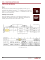
1
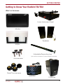
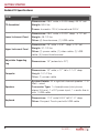
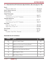
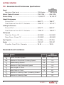
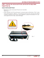
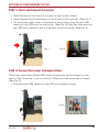
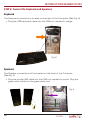
INSTRUCTION MANUAL
Manufactured in the United States
www.redbirdflightsimulations.com
DISCLAIMER
*With optional rudder pedals
Information in this manual is subject to change without
notice and does not represent a commitment on the
part of the licensor.
©2013 Redbird Flight Simulations, Inc.
All rights reserved.
Trademarks used in this text: Redbird, Redbird Flight Simulations,
Redbird TD and TD2, the Redbird TD and TD2 logo and the Redbird
logo are trademarks of Redbird Flight Simulations, Inc., and are
used by Redbird under license. Microsoft Flight Simulator, Microsoft
Windows, Microsoft Game Studios are either trademarks or registered
trademarks of Microsoft in the US and other countries.
The software and hardware described in this document are provided
under a license agreement. The software and hardware may be used or
copied only in accordance with the terms of the license agreement.
Other trademarks and trade names may be used in this
document to refer to the entitles claiming the marks and
names or their products. Redbird Flight Simulations,
Inc. disclaims any proprietary interest in trademarks and
trade names other than its own.
April 2013 Rev. 5.0
AA
APPROV
ED
BATD
F
The Redbird TD/TD2 are an FAA approved Basic Aircraft
Training Device (BATD)* that represents a generic highwing, single-engine, piston aircraft. This manual contains
information on how to setup, use and troubleshoot the
Redbird TD/TD2. The reader of this manual is expected
to know how to fly an aircraft or to be participating
in a structured and approved flight training program.
This manual is in no respect a tutorial in visual flight,
instrument flight or navigation. Its only purpose is to
introduce the Redbird TD/TD2 hardware and software to
enable a pilot to use this training device.
CONTENTS
4
5
7
8
CHAPTER 1- GETTING STARTED
Getting to Know Your Redbird TD/TD2
Simulated Aircraft Performance Specifications (TD)
Simulated Aircraft Performance Specifications (TD2)
10 CHAPTER 2 - SETTING UP YOUR REDBIRD TD/TD2
11 Preflight Checklist
18 Optional Setup and Equipment
20
24 29
35 36
37
CHAPTER 3 - USING YOUR REDBIRD TD/TD2
Starting a Flight on a TD
Starting a Flight on a TD2
While in Flight
Keyboard Functions for Glass Panel
Keyboard Functions for Analog/Steam Panel
43 CHAPTER 4 - TIPS
44 Practicing Approaches
53 54 57 58 CHAPTER 5 - TROUBLESHOOTING
Troubleshooting Tips
Keeping Your Software Up-to-date
Learning More, Service and Support
1
GETTING STARTED
Your Redbird TD/TD2 is designed for easy setup and operation so
that you can begin flying immediately.
!
Retain all original packaging and shipping materials.
!
Any unauthorized software on your Redbird TD/TD2
is prohibited and will void your warranty.
GETTING STARTED
Getting to Know Your Redbird TD/TD2
What’s in the boxes:
Lower Instrument Panel
Monitor
Speakers
Acrylic
Adjustable Supporting Leg*
(*Not needed if installed on optional Redbird TD Table)
Thumbscrews
Panel Thumbscrews
Keyboard
Computer
5
GETTING STARTED
Redbird TD Specifications:
ITEM
SPECS
Dimensions: 28.9” wide, x 24.25 deep, 49.12” tall
TD Assembled
Weight: 96.5 lbs
Power: domestic-120 V, international-220V
Dimensions: 28.5” wide, x 24.25” deep , x 10” tall
Lower Instrument Panel
Weight: 48-1/2 lbs
Other: (4) thumbscrews, (1) USB cable
Dimensions: 28” wide, x 6.81” deep, x 19” tall
Upper Instrument Panel
Adjustable Supporting
Leg
Weight: 37-1/2 lbs
Other: (1) power cable, (1) video cable, (1) USB
cable, (4) loose thumbscrews
Dimensions: 19” (extends to 22”)
Dimensions: 16” wide, x 17” tall x 7-1/4” deep
Computer
Weight: 10 1/2 lbs
Other: (1) power cable
System Details: 22 x right/left channel speaker - 1.5
Watt - wired
Speakers
Keyboard
6
Connector Type: 1 x headphones (mini-phone
stereo 3.5 mm), 1 x DC power input, 1 x audio line-in
with 1 USB cable
Dimensions: 11.3” wide X 8.9” tall X 1.0” deep
Other: Compact Touch-pad with USB cable
GETTING STARTED
TD - Simulated Aircraft Performance Specifications: (See next page for TD2)
Speed
Maximum Sea Level................................................................ 126 Knots
Rate of Climb at Sea Level................................................................ 730 FPM
Service Ceiling ............................................................................... 14,000 FT
Takeoff Performance
Ground Roll ............................................................................ 960 FT
Total Distance Over 50 FT Obstacle ........................................ 1630 FT
Landing Performance
Ground Roll ............................................................................ 575 FT
Total Distance Over 50 FT Obstacle ........................................ 1335 FT
Stall Speed
Flaps Up, Power Off ............................................................... 48 KIAS
Flaps Down, Power Off ........................................................... 43 KIAS
Fuel Capacity ................................................................................. 56 GAL
Engine .......................................................................................... 180 HP
Propeller: Fixed Pitch, Diameter .............................................. 76 IN
Simulated Aircraft Limitations:
SYMBOL
SPEED
KIAS
VNE
Never Exceed Speed
163
VNO
Maximum Structural Cruising Speed
129
VA
Maneuvering Speed
98
VFE
Maximum Flap Extended Speed
110
VX
Best Angle of Climb
63
VY
Best Rate of Climb
75
7
GETTING STARTED
TD2 - Simulated Aircraft Performance Specifications:
High
Performance
Speed
Maximum Sea Level ........................................ 126 Knots ........ 145 Knots
Rate of Climb at Sea Level......................................... 730 FPM........... 924 FPM
Service Ceiling ........................................................ 14,000 FT ......... 18,100 FT
Takeoff Performance
Ground Roll ..................................................... 960 FT .............. 795 FT
Total Distance Over 50 FT Obstacle ................. 1630 FT ............ 1514 FT
Landing Performance
Ground Roll ..................................................... 575 FT .............. 590 FT
Total Distance Over 50 FT Obstacle ................. 1335 FT ............ 1350 FT
Stall Speed
Flaps Up, Power Off ....................................... 48 KIAS ............ 54 KIAS
Flaps Down, Power Off ................................... 43 KIAS ............ 49 KIAS
Fuel Capacity ......................................................... 56 GAL ............. 92 GAL
Engine .................................................................. 180 HP ............. 230 HP
Propeller: Fixed Pitch, Diameter ......................76 IN ................. 79 IN
Simulated Aircraft Limitations:
SYMBOL SPEED
8
KIAS
HIGH
PERFORMANCE
VNE
Never Exceed Speed
163
175
VNO
Maximum Structural Cruising Speed
129
140
VA
Maneuvering Speed
98
110
VFE
Maximum Flap Extended Speed
110
140
VX
Best Angle of Climb
63
64
VY
Best Rate of Climb
75
84
VLO
Maximum Landing Gear Operating Speed
-
180
VLE
Maximum Landing Gear
-
152
GETTING STARTED
What’s on the back of your Redbird TD/TD2:
Power Port
Power Switch
Voltage Switch
USB Ports
Ethernet Port
Video Port
Speaker Port
Monitor
Computer
Acrylic
Lower
Instrument
Panel
9
2
Setting Up Your Redbird
TD/TD2
This chapter will guide you through the Redbird TD/TD2 setup.
SETTING UP YOUR REDBIRD TD/TD2
Preflight Checklist
USE THE FOLLOWING ITEMS TO SETUP YOUR REDBIRD TD/TD2
Lower Instrument Panel with (4) thumbscrews, (1) USB cable
Adjustable Supporting Leg
Upper Instrument Panel with (1) power cable, (1) video cable, (1) USB
cable, (4) loose thumbscrews
Computer with power cable
Keyboard
Speakers
THINGS TO KNOW PRIOR TO INSTALLATION
!
You will need a sturdy, solid table with a maximum tabletop thickness of
2.25” including rails and the underlying structure.
There must be at least 29” between the legs.
If you are not installing your TD/TD2 on the optional Redbird TD Table,
you must install the adjustable supporting leg.
No tools are required for installation. The assembly is performed by
hand-tightening only. The use of tools may lead to damage.
Lift all items from both sides using correct lifting techniques.
Seek assistance when lifting larger items.
Retain all original packaging and shipping materials.
Any unauthorized software on your Redbird TD/TD2 is prohibited and
will void your warranty.
11
SETTING UP YOUR REDBIRD TD/TD2
STEP 1: Position the Instrument Panels and Install the Adjustable
Supporting Leg
Lower Instrument Panel
• Slide the Lower Instrument Panel onto the table.
(See Fig. 1)
• Hand-tighten the (4) thumbscrews to ensure secure clamping of the Lower
Instrument Panel to tabletop. The panel should be firmly secured and fixed
in place. Tighten only as much as is needed to prevent movement. Do not
over-tighten as this may cause damage.
Do Not Use Tools
Hand Tighten Only
Fig. 1
12
SETTING UP YOUR REDBIRD TD/TD2
Install the Adjustable Supporting Leg*
• Position the Adjustable Supporting Leg under the threaded opening at the
bottom right hand corner of the Lower Instrument Panel. (See Fig. 2)
• Hand-tighten the leg so that it is fully secured to the Lower Instrument
Panel.
• To adjust the Adjustable Supporting Leg height, twist the lower portion of
the leg until the foot pad has reached the floor. Hand-tighten the wing nut
to secure the leg. (See Fig. 3)
Fig. 2
Fig. 3
(*Not needed if installed on optional Redbird TD Table)
13
SETTING UP YOUR REDBIRD TD/TD2
Monitor
• Position the Monitor on top of Lower Instrument Panel, so that the holes
are aligned. (See Fig. 4)
• Pass the (4) loose thumbscrews through the aligned holes to attach the
Monitor and Lower Instrument Panels.
• Hand-tighten the thumbscrews so that the Monitor is fully secured.
(See Fig. 5)
Fig. 4
Fig. 5
STEP 2: Position the Computer
• Place the Computer behind the Monitor on the Lower Instrument Panel.
(See Fig. 6)
• Ensure the back of the Computer is positioned to the right of the Monitor
for easy access to the Computer ports.
Monitor
Computer
Acrylic
Lower
Instrument
Panel
14
Fig. 6
SETTING UP YOUR REDBIRD TD/TD2
STEP 3: Place and Connect the Acrylic
• Slide the Acrylic onto the four screws on the monitor frame.
• Hand-tighten the thumbscrews so the Acrylic is fully secured. (See Fig. 7)
• On the bottom left corner of the back of the monitor, plug the red USB
cable into the USB port on the Acrylic. (See Fig. 8) Plug the other end into
the USB port marked in red on the back of the computer. (See Fig. 9)
Fig. 7
Fig.8
STEP 4: Connect the Lower Instrument Panel
The Lower Instrument Panel USB cable connections will be located on the
back of the Computer. Look for the four USB ports that are similar in shape.
(See Fig. 9)
• Plug the blue USB cable into the USB port marked in blue.
Fig.9
15
SETTING UP YOUR REDBIRD TD/TD2
STEP 5: Connect the Keyboard and Speakers
Keyboard
The Keyboard connection is located on the back of the Computer. (See Fig. 8)
• Plug the USB keyboard cable into the USB port marked in orange.
Fig.8
Speakers
The Speaker connections will be located on the back of the Computer.
(See Fig. 9)
• Plug the purple USB cable into the USB port marked in purple. Plug the
green audio cable into the green audio port.
Fig.9
16
SETTING UP YOUR REDBIRD TD/TD2
STEP 6: Connect the Video and Power Cables
• Plug one Power Cable into the back of the monitor. (See Fig. 10) Plug the
opposite end into a standard wall outlet.
• Plug the white Video Cable into the white marked video port on the back of
the computer. Plug the opposite end into the back of the monitor.
(See Fig. 11)
• Plug the other Power Cable into the green marked power port on the back
of the computer. (See Fig. 12) Plug the opposite end of the green Power
Cable into a standard wall outlet. (Volt Setting:115V)
Fig.10
Left Side - Power
Fig.11
Right Side - Video
IMPORTANT - VOLTAGE
SETTING:
Default voltage is set
at 115. To change the
voltage to your local
standard, slide the red
button located near the
power outlet so that it
reads 230V. (See Fig. 11)
Fig.11
17
SETTING UP YOUR REDBIRD TD/TD2
STEP 7: Optional Setup and Equipment
Internet Setup
To access the Internet for Redbird software updates and downloads:
• Connect one end of an Ethernet cable (not included) to the Ethernet port
on the back of your Redbird TD/TD2 Computer.
• Connect the other end to your network outlet. Redbird will automatically
notify you if there are any updates after you’ve powered on the TD/TD2.
Ethernet Port
18
SETTING UP YOUR REDBIRD TD/TD2
Rudder Pedal Setup
The Redbird TD/TD2 is compatible with Saitek Pro Flight Rudder Pedals and
CH Pro Pedals.
• Plug the USB pedals into an empty USB port located on the back of the
Computer.
Install the rudder pedals prior to powering on the Redbird TD/TD2.
19
3
Using Your Redbird TD/TD2
The Redbird TD/TD2 has many features which will help improve
your flying skills. For example, you can fly anywhere in the world,
day or night in a variety of weather conditions.
USING YOUR REDBIRD TD/TD2
Start Up
• On the back of the computer, ensure the power switch is turned on.
(See Fig.12)
Fig.12
• Push the power button located on the front of the Computer. (See Fig.13)
Fig.13
21
USING YOUR REDBIRD TD/TD2
The Redbird TD/TD2 will start and the Begin Flight Menu will appear.
(See Fig. 14)
Begin Flight Menu
Fig.14
22
USING YOUR REDBIRD TD/TD2
If you get a System Failed, Check Connections, refer to
page 45 for troubleshooting.
System Failed
23
USING YOUR REDBIRD TD
STARTING A FLIGHT ON THE TD (See page 29 for TD2)
With the Redbird TD you can specify where your flight begins and under what
conditions. To begin a flight, select the following conditions:
1. AIRCRAFT LOCATION
2. TIME OF DAY
3. WEATHER CONDITIONS
STEP 1: Set Aircraft Location
You can choose to start your flight ON THE GROUND at an airport or
IN THE AIR.
24
USING YOUR REDBIRD TD
To start your flight ON THE GROUND:
• Type in the ICAO designation for the airport.
• Select the RUNWAY from the drop down box.
To start your flight IN THE AIR:
Enter the aircraft position in this order:
1. NM FROM - enter the distance from a
desired airport NAVAID or intersection.
2. NAV IDENT - enter the airports ICAO
identifier, NAVAID, or Intersection.
The Redbird TD/TD2 will notify you if you’ve entered an invalid airport
NAVAID or Intersection.
Invalid NAVAID
3. BEARING - enter the bearing from the desired NAVAID
4. ALTITUDE - enter the altitude in feet MSL.
If the chosen altitude is too low for the position specified, the aircraft
will be placed at 1000 feet at the selected NAVAID.
5. HDG - enter the aircraft heading.
25
USING YOUR REDBIRD TD
STEP 2: Set Time
Select DAY or NIGHT.
STEP 3: Set Weather Conditions
Enter weather conditions.
WIND
Enter the desired wind direction, speed and gusts.
VISIBILITY
Use the drop down box to select the visibility on the ground. Visibility coverage
ranges from 1/16 up to 10+ miles.
26
USING YOUR REDBIRD TD
RAIN
Select the desired rain intensity. You may choose from:
NONE
LIGHT
MODERATE
HEAVY
CLOUD COVERAGE
Select the cloud coverage.
NONE
FEW
SCATTERED
BROKEN
OVERCAST
Enter cloud base in feet MSL.
27
USING YOUR REDBIRD TD
STEP 4
BEGIN FLIGHT:
Once you are satisfied with your selections,
click BEGIN FLIGHT.
Congratulations
you are now ready to fly.
All flights begin in a paused state. To begin flying, press the F12
pause button on the keyboard.
Other Options
END A FLIGHT
Press the ESC key on your keyboard to END FLIGHT
ESC
END
FLIGHT
SHUTDOWN THE REDBIRD TD/TD2
Click the SHUTDOWN button from the
Begin Flight Menu to turn off your Redbird TD/TD2.
28
USING YOUR REDBIRD TD2
STARTING A FLIGHT ON THE REDBIRD TD2 (See page 24 for the TD)
With the Redbird TD2 you can specify where your flight begins and under what
conditions. To begin a flight, select the following conditions:
1. AIRCRAFT OPTIONS
2. AIRCRAFT LOCATION
3. TIME OF DAY
4. WEATHER CONDITIONS
Begin Flight Menu
STEP 1: Select Aircraft Options
You can select/deselect all that apply:
• Retractable Gear
• Constant Speed Prop
• High Performance
If you choose not to select either of these
options, the TD2 will simulate a 180 HP generic
single engine aircraft.
29
USING YOUR REDBIRD TD2
STEP 2: Set Aircraft Location
You can choose to start your flight On the Ground at an airport or
In the Air.
30
USING YOUR REDBIRD TD2
To start your flight ON THE GROUND:
• Type in the ICAO designation for the
airport.
• Select the RUNWAY from the drop
down box.
To start your flight IN THE AIR:
Enter the aircraft position in this order:
1. NM FROM - enter the distance from a
desired airport NAVAID or intersection.
2. NAV IDENT - enter the airports ICAO
identifier, NAVAID, or Intersection.
The Redbird TD/TD2 will notify you if you’ve entered an
invalid airport NAVAID or Intersection.
Invalid NAVAID
1. BEARING - enter the bearing from the desired NAVAID
2. ALTITUDE - enter the altitude in feet MSL.
If the chosen altitude is too low for the position specified, the
aircraft will be placed at 1000 feet at the selected NAVAID.
3. HDG - enter the aircraft heading.
31
USING YOUR REDBIRD TD2
STEP 3: Set Time
Select DAY or NIGHT.
STEP 4: Set Weather Conditions
Enter weather conditions.
WIND
Enter the desired wind direction, speed and gusts.
VISIBILITY
Use the drop down box to select the visibility on the ground. Visibility
coverage ranges from 1/16 up to 10+ miles.
32
USING YOUR REDBIRD TD2
RAIN
Select the desired rain intensity. You may choose from:
NONE
LIGHT
MODERATE
HEAVY
CLOUD COVERAGE
Select the cloud coverage.
NONE
FEW
SCATTERED
BROKEN
OVERCAST
Enter cloud base in feet MSL.
33
USING YOUR REDBIRD TD2
STEP 4
BEGIN FLIGHT:
Once you are satisfied with your selections,
click BEGIN FLIGHT.
Congratulations
you are now ready to fly.
All flights begin in a paused state. To begin flying, press the F12
pause button on the keyboard.
Other Options
END A FLIGHT
Press the ESC key on your keyboard to END FLIGHT
ESC
END
FLIGHT
SHUTDOWN THE REDBIRD TD/TD2
Click the SHUTDOWN button from the
Begin Flight Menu to turn off your Redbird TD/TD2.
34
USING YOUR REDBIRD TD/TD2
WHILE IN FLIGHT
KEYBOARD FUNCTIONS
The function keys on the keyboard allow you to end a flight, enable/disable
aircraft failures, show/hide gauges, pause/resume flight, clear/show visibility,
and show/hide the flight analysis window. Pressing a function key will activate
the failure/action. Pressing it again will disable this failure/action. The following
pages will define those key functions for the Redbird TD/TD2 steam gauge
configuration.
35
USING YOUR REDBIRD TD/TD2
Keyboard Functions for TD/TD2 with Glass Panel
ESC
F1
F2
F3
F4
F5
END
FLIGHT
BACKUP
GAUGES
ZERO
VIS
FAIL
ENGINE
FAIL
ELEC
FAIL
AHRS
GLASS GAUGE
FAILURES
HOT KEY
DESCRIPTION
End Flight
ESC
Terminates the active flight and returns
you to the Begin Flight Menu
Add’l Gauges
F1
Displays the aircraft’s gauges
(see image on page 38)
Zero Visibility
F2
Reduces the visibility to zero
Fail Engine
F3
Fails the engine
Fail Electrical
F4
Fails the electrical system
Fail AHRS
F5
Fails the attitude and heading reference
system
F6
F7
F8
F9
F11
F12
FAIL
HDG
FAIL
ADC
FAIL
EAU
FAIL
IAU
ANALYZE
FLIGHT
PAUSE
FLIGHT
GLASS GAUGE
FAILURES
HOT KEY
DESCRIPTION
Fail HDG
F6
Fails the heading indicator
Fail ADC
F7
Fails the air data computer
Fail EAU
F8
Fails the engine/airframe unit
Fail IAU
F9
Fails the integrated avionics unit
Analyze Flight
F11
Displays Flight Analysis window (see
page 39 to learn how to use this feature)
Pause Flight
F12
Pauses flight
Brake
Ctrl + B
Wheel Brakes
36
USING YOUR REDBIRD TD/TD2
Keyboard Functions for TD/TD2 with Analog/Steam Panel
ESC
F1
F2
F3
F4
F5
END
FLIGHT
BACKUP
GAUGES
ZERO
VIS
FAIL
ENGINE
FAIL
ELEC
FAIL
ALT
STEAM GAUGE
FAILURES
HOT KEY
DESCRIPTION
End Flight
ESC
Terminates the active flight and returns
you to the Begin Flight Menu
Add’l Gauges
F1
Displays the aircraft’s gauges
(see image on page 38)
Zero Visibility
F2
Reduces the visibility to zero
Fail Engine
F3
Fails the engine
Fail Electrical
F4
Fails the electrical system
Fail ALT
F5
Fails the altimeter
F6
F7
F8
F9
F11
F12
FAIL
PITOT
FAIL
STATIC
PORT
FAIL
VACUUM
FAIL
AUTOPILOT
ANALYZE
FLIGHT
PAUSE
FLIGHT
STEAM GAUGE
FAILURES
HOT KEY
DESCRIPTION
Fail Pitot
F6
Fails the pitot
Fail Static Port
F7
Fails the static port
Fail Vacuum
F8
Fails the vacuum
Fail Autopilot
F9
Fails the autopilot
Analyze Flight
F11
Displays Flight Analysis window (see
page 39 to learn how to use this feature)
Pause Flight
F12
Pauses flight
Brake
Ctrl + B
Wheel Brakes
37
USING YOUR REDBIRD TD/TD2
F1- Show Backup Gauges:
Pressing the F1 key displays the backup gauges so that you can practice
partial panel flying. Glass TD/TD2 shown below.
Pressing the F1 key displays the trim and flap gauges. Steam TD/TD2
shown below.
38
USING YOUR REDBIRD TD/TD2
F11- Flight Analysis
Pressing the F-11 key will display the Flight Analysis window. Flight Analysis
helps you evaluate your skills as a pilot on any flight. The Flight Analysis dialog
box contains a map depicting the horizontal path of the flight, a vertical analysis
graph, and controls for animating the flight analysis playback. You do not need
to complete a flight before viewing the analysis.
Flight Analysis will reset under the following conditions:
• The aircraft crashes
• You select or create a new flight
Controls
Use the controls to play, rewind, fast forward, or stop the flight analysis
playback.
39
USING YOUR REDBIRD TD/TD2
Using the Playback Slider
Use the playback slider to move to a particular point in the flight analysis. You
can drag the slider and move across a large area, or move the slider slowly
to view a second-by-second analysis. Dragging the playback slider affects
playback on the map, as well as in the vertical analysis graph.
Using the Flight Analysis Map
The flight analysis map displays the horizontal path of your flight. When you
play the flight analysis, the airplane on the map will move along the path you
flew, trailing a red line. You can observe how well you flew a traffic pattern at an
airport or how well you flew an instrument approach.
You can zoom in or out on the map, or you can choose not to display airspace
lines or other elements.
To view a larger or smaller area of the map:
• Click the plus or minus buttons above the map to zoom in or out.
To turn a map element on or off :
• Click on the element’s corresponding icon above the map.
To see the horizontal path of the flight:
• Click the control arrow play or drag the playback slider and observe the
small airplane on the map.
40
USING YOUR REDBIRD TD/TD2
Using the Dynamic Text Boxes
The latitude, longitude, altitude, heading and airspeed is
displayed on the left side of the map. When you play the flight
analysis the values in these text boxes update as the flight
progresses-a valuable tool for analyzing how well you held
heading, altitude or airspeed. (You cannot type new values
in the dynamic text boxes when using the map in Flight
Analysis.)
To see dynamic text box values:
• Click the forward or rewind controls or drag the playback
slider and view the values change in the dynamic text
boxes.
Using the Vertical Analysis Graph
The vertical analysis graph displays your vertical path along the flight. The left
side of the graph is marked off in altitude. The bottom of the graph is marked
off in distance. The graph helps you evaluate how well you held altitude, or how
precisely you ascended or descended.
To see the vertical path of the flight:
• Click the forward or rewind controls or drag the playback slider and view
the values change in the dynamic text boxes , or zoom in and out by
clicking the plus or minus buttons.
41
USING YOUR REDBIRD TD/TD2
Using the Playback Timer
Use the Playback Timer to play back parts of the flight, or to skip to a particular
part of the flight. You will also see the Playback Timer values change during
control playback or if you drag the playback slider. To use the timer, click on the
hours, minutes, or seconds or click the spin box to adjust the time.
Using Time Compression
Use time compression to slow down or speed up the playback of the flight
analysis from 0.025 times (or 1/40th) normal speed to 128 times normal speed.
To adjust Time Compression, select a speed here.
42
4
Tips - Practicing Approaches
This chapter provides tips on how to setup a flight to practice
instrument approaches.
TIPS - PRACTICING APPROACHES
Practicing Approaches
Here are a few guidelines that will help you to setup a flight to practice
instrument approaches. Once you have selected the approach that you would
like to fly, all of the necessary settings for aircraft position and weather may be
derived by studying the approach plate (NOS and Jeppesen approach plates
are represented throughout the setup). For this example, we have chosen the
ILS 17L into Austin-Bergstrom International Airport. We will set the airplane up
on a vector to intercept the final approach course.
Jeppesen Approach Plate
44
NOS Approach Plate
TIPS - PRACTICING APPROACHES
STEP 1: Determine the Aircraft’s Starting Position
DISTANCE from the selected airport:
To determine the proper distance, find the distance from the final approach fix
to the runway on the approach plate and add 10 miles.
Jeppesen Approach Plate
NOS Approach Plate
In our example the distance from the final approach fix to the
runway is 6 miles (5.6 + 0.3 + 0.1 = 6.) Therefore our starting
distance will be 16 miles (10 + 6 = 16.)
16
KAUS
348
2500
143
45
TIPS - PRACTICING APPROACHES
ICAO code for the selected airport:
Enter the ICAO code for the airport. For our example the code is KAUS.
Jeppesen Approach Plate
NOS Approach Plate
When using NOS charts, if the ICAO code found on the approach
plate is a three letter code (ex. AUS), a “K” must be added in the
continental U.S. to the beginning of the code (KAUS). If the code
contains a number (ex. T82,) no “K” is needed.
16
KAUS
348
2500
143
46
TIPS - PRACTICING APPROACHES
BEARING from the selected airport:
To determine the proper bearing from the airport, find the reciprocal of
the final approach course and subtract 5°. If you are using NOS charts, the
reciprocal will be published, however if you are using charts that do not publish
the reciprocal of the final approach course, you will need to calculate it. To do
this, do one of the following:
• If the final approach course is 001° - 180°: add 180° to the final
approach course
• If the final approach course is 181° - 360°: subtract 180° from the
final approach course
Jeppesen Approach Plate
NOS Approach Plate
In our example the final approach course is 173°, the reciprocal of
which is 353°. Therefore our bearing will be 348° (353° - 5°).
16
KAUS
348
2500
143
47
TIPS - PRACTICING APPROACHES
Aircraft ALTITUDE:
For altitude, use the assigned altitude at the final approach fix.
Jeppesen Approach Plate
NOS Approach Plate
In our example the altitude at the final approach fix is 2500’.
Therefore our starting altitude will be 2500’.
16
KAUS
348
2500
143
48
TIPS - PRACTICING APPROACHES
Aircraft HEADING:
To determine the proper aircraft heading, take the final approach course and
subtract 30°.
Jeppesen Approach Plate
NOS Approach Plate
In our example the final approach course is 173°. Therefore our
heading will be 143° (173° – 30°).
16
KAUS
348
2500
143
49
TIPS - PRACTICING APPROACHES
STEP 2: Set the Weather
Wind:
Set the wind to be favorable to the desired runway. In our
example, the desired runway is 17L, therefore we will set our
wind to 170 at 5 kts with no gusts. To challenge yourself, add
gusts or set a crosswind.
170
5
0
Visibility on the Ground:
Find the visibility minimums on the approach plate. In our
example, the visibility minimum is 1800 feet, therefore the
visibility should be set at no less than ½ mile.
Jeppesen Approach Plate
NOS Approach Plate
50
1/2 mile
TIPS - PRACTICING APPROACHES
Rain:
Choose the desired rain intensity.
Cloud Coverage:
Choose overcast.
Cloud Bases:
Set the cloud bases to the altitude (MSL) where you would like to break out. If
you would like to shoot the approach to minimums, set the cloud bases at or a
few feet above your decision height.
Jeppesen Approach Plate
NOS Approach Plate
In our example the decision height is 692’ MSL. Therefore we will
set our cloud bases to 750’ MSL.
750
51
TIPS - PRACTICING APPROACHES
STEP 3: Click Begin Flight
All flights begin in a paused state. To begin flying, press the F12
pause button on the keyboard.
52
5
Troubleshooting
This chapter contains solutions to problems which may prevent you from flying
your Redbird TD/TD2. If you have a problem with your Redbird TD/TD2, there is
usually a simple and quick solution.
TROUBLESHOOTING
Troubleshooting Tips
Redbird lists solutions to problems from the most likely to least likely solution.
Computer won’t power on or start up:
• Make sure the power switch on the back of the computer is turned on
(see page 21.)
• Ensure that all power cables are firmly connected to the computer and to
the electrical outlet.
• Ensure the power cables are not severely bent.
• Test the power cables and outlets by plugging them into another wall
outlet.
• Test the wall outlet by plugging in other devices.
• Check to see if the power light is on (located in front of the computer near
the power button.)
• If the power light is on, push down and hold the power button for at least
10 seconds until the computer turns off .
• Restart the computer.
The computer stops responding or a solid blue screen appears:
• If you are unable to get a response by pressing a key on your keyboard,
push down and hold the power button for at least 10 seconds until the
computer turns off.
• Restart the computer.
There’s no sound from the speakers:
• Check the speaker’s USB and audio cable to ensure it’s plugged in
correctly.
• Check for damaged or frayed cables.
• To eliminate any possible interference or static, turn off nearby fans and
fluorescent or halogen lights.
• Test audio by plugging in ear buds in the audio port.
54
TROUBLESHOOTING
Keyboard is inoperable:
• Check the keyboard’s USB cable to ensure it’s plugged in correctly.
• Check for damaged or frayed cables.
• Push down and hold the power button for at least 10 seconds until the
computer turns off .
• Restart the computer.
The Begin Flight Menu doesn’t appear:
• Ensure the power and video cables are firmly secured.
• Ensure the video cables are not severely bent or have broken pins.
• Test the power outlets by plugging it into another wall outlet.
• Test the wall outlet by plugging in other devices.
• Ensure the power light is on (located in front of the computer.)
• If the light is on, push down and hold the power button for at least 10
seconds until the computer turns off.
• Restart the computer.
Unable to launch flight in the Begin Flight Menu:
• If the Begin Flight Menu displays a notification, System Failed, Check
Connections, ensure that all power and USB cables are connected to the
computer.
• Ensure all flight conditions are chosen and filled in correctly and that there
are no errors.
• Ensure the keyboard is properly connected to the computer (see keyboard
is in operable.)
Unable to end flight:
• If the ESC button on the keyboard is inoperable, make sure the keyboard is
properly connected to the computer (see keyboard is inoperable.)
• Push down and hold the power button for at least 10 seconds until the
computer turns off.
• Restart the computer.
55
TROUBLESHOOTING
In the Begin Flight Menu, system says Failed, Check Connections:
• Ensure the USB cables are properly connected to the computer.
• Push down and hold the power button for at least 10 seconds until the
computer turns off .
• Restart the computer.
The switches, yoke, throttle, knobs and or buttons are inoperable:
• Ensure all the USB cables are firmly secured.
• Try turning the knobs smoothly and steady at a moderate speed for best
results.
• Restart the computer.
If the problems has remained unresolved, visit our website at
www.redbirdflightsimulations.com, or contact Redbird Service
Department for additional support.
[email protected]
Monday - Friday 7:30 am - 6:00 pm CST
(512) 301-0755
56
TROUBLESHOOTING
KEEPING YOUR SOFTWARE UP-TO-DATE
Redbird provides proactive notification of software updates for your Redbird
TD/TD2. If your computer is connected to the Internet, your Redbird TD/TD2
will ask you if you would like to run the Update Wizard. If you are not connected
to the Internet see Chapter 1 - Setting Up your Redbird TD/TD2, Optional
Equipment on page 16 for Internet setup instructions.
For TD/TD2 Updates:
• Turn on the Redbird TD/TD2.
• If there are updates, the Redbird
Updater dialog box will appear in
the Begin Flight Menu.
• Redbird will ask if you would like
to run the Update Wizard now.
(Fig. 1)
• Choose YES to run the Update
Wizard.
Note: If you choose NO, The
Redbird Updater will disappear.
The Updater will appear each
time your turn on your Redbird
TD/TD2 until you choose Yes.
• The Redbird Update Wizard will
appear. Choose the Internet
connection type. Choose Next.
(Fig. 2)
• Select all product updates. Click
Next. (Fig. 3)
• Press OK to continue. (Fig.4)
• Click Finish once the update is
complete. (Fig. 5)
• You may now resume entering
your flight conditions in the Begin
Flight Menu.
57
TROUBLESHOOTING
Learning More, Service and Support
The Redbird TD/TD2 comes with a ninety (90) day warranty, which includes
software updates and service and replacement parts as needed. After the first
90 day warranty, Redbird offers optional one or two (1 or 2) year warranty
extensions.
!
Any unauthorized software on your Redbird TD/TD2
is prohibited and will void your warranty.
Contact Redbird Service and Support if you:
• Can’t find what you are looking for in this manual
• Need to return items for warranty and repair
• Lost your original shipping and packaging materials
• Have problems with your order, such as missing or wrong parts
[email protected]
Monday - Friday 7:30 am - 6:00 pm CST
(512) 301-0755
Contact King Schools:
• For incorrect billing (have your invoice handy)
• To order another Redbird TD/TD2
• To order rudder pedals
• To extend your warranty
King Schools
1-800-854-1001
(billing and sales)
58
TROUBLESHOOTING
Returning Items for Warranty and Repair
Prepare all items being returned for repair as follows:
1. Prior to returning materials, ensure you’ve tried all troubleshooting
(page 45) and spoken with a Redbird Service Department personnel.
2. Call Redbird Service Department at 512-301-0755
Monday through Friday 7:00 am - 7:00pm CST (Central Standard
Time), excluding holidays, to obtain a return
3. Material Authorization Number (RMA#.)
4. The following guidelines apply when packing the product for repair:
• Include your name, address and contact phone number
• All products being returned for warranty service must be carefully
packed in the original box and packing materials. Any damage
incurred due to improper packing or use of other packing materials
will void the warranty and all repairs will be chargeable to customer.
• The RMA# must be clearly printed on the shipping label (not on
the box.)
5. During Redbird’s product warranty, the customer will be responsible for
postage, insurance and/or shipping cost incurred to ship the product
to Redbird’s Customer Service Department, and Redbird will be
responsible for the shipping cost incurred to return the product back to
the customer’s specified address within the contiguous United States
(48 states and DC.)
6. You also assume the risk of loss during shipment to Redbird Services.
7. Collect On Delivery (C.O.D.) packages are not accepted.
8. *The TD/TD2 packaging and shipping materials are designed for
protection. If the Redbird TD/TD2 is not shipped in its original
packaging to Redbird Customer Service Department for custom repair
and support, Redbird will not be liable for damages other than what
is specified by the client. If needed, Redbird will provide replacement
packaging at the customer’s expense.
Returning Address:
Redbird Flight Simulations
Attention: Customer Service Department
2301 E. St. Elmo Rd., Suite 100
Austin, TX 78744
59
TROUBLESHOOTING
WARRANTY
WARRANTY PERIOD
The warranty hereof shall mean a period of 90 days from the original date of purchase for parts &
labor. In the event that the product required for replacement is no longer in production and/or is
obsolete, Redbird will repair the unit with similar or like parts of equal function. If a similar or like part
is not available, a charge may be incurred to the owner, for any upgraded part substituted.
WARRANTY TERMS AND CONDITIONS ON Redbird TD/TD2 products
1. Redbird warrants that the product you have purchased is free from manufacturing defects in
materials and workmanship when dispatched from our warehouse.
2. The receipt of purchase shall be provided as proof of the date of purchase and the warranty
period commences as of that date. Proof of purchase will be required in the event of any
discrepancy.
3. The warranty will not apply to any product purchased from a dealer/reseller other than an
authorized Redbird dealer/reseller.
4. This warranty applies to the original purchaser only and is not transferable.
5. The warranty automatically becomes void if the product has been physically damaged or
rendered defective (a) as results of an accident, misuse, fire, lightning, malicious damage,
water damage, abuse or other circumstances beyond Redbird’s control; (b) by the use of
parts or peripherals not authorized by Redbird; (c) as a result of normal wear and tear; (d)
by use in an improper operating environment; (e) by improper installation and operation or
unauthorized modification of the product; (f ) by the serial number or product code sticker
being removed or defaced; (g) as a result of a service rendered by anyone other than Redbird
authorized service center or its authorized service agents; (h) as a result of the product not
being operated in conformity with Redbird’s user manual.
6. Replacement product or parts may include re-manufactured or refurbished parts or
components. All replacement parts are warranted for (90) days.
7. Your LCD Monitor included contains thousands of individual pixels. These monitors typically
contain a small number of pixels that do not function normally. Your display has been
inspected and is in compliance with the manufacturer’s specifications, indicating that any
pixel defects do not affect the operation or use of your monitor.
8. In all circumstances, the user must ensure that the product is packed in appropriate packing.
Any damage due to improper packing will void product warranty and the cost incurred to
repair damaged product will be customer’s responsibility.
9. Software related faults resulting from customer installed software, incorrect software
installation or usage or software viruses shall not be considered as product faults and may
incur a charge for rectification.
10.Redbird is not responsible for damages of any kind including, but not limited to, direct
or indirect damages, lost profits, lost savings, or other special incidental, exemplary or
consequential damages whether for breach of contract, tort or otherwise, or whether arising
out of the use of or inability to use the product, even if Redbird or any dealer, distributor or
authorized service provider / partner have been advised of the possibility of such damages,
or any claim by any other party. This warranty does not deprive the Owner/Customer of any
rights or remedies under that Trade Practices Act 1974 and/or under any other applicable
commonwealth, State or Territory legislation.
60
TROUBLESHOOTING
WARRANTY (con’t)
To Obtain Warranty Service:
1. Contact our Customer Service Department Monday through Friday 7:00am – 7:00pm CST
(Central Standard Time), excluding holidays, to determine the nature of the problem. If
product needs to be returned for repair, an RMA # (Return Material Authorization number) will
be issued. Redbird’s Authorized Service Centers will not accept any returned product without
RMA #.
2. The following guidelines apply when packing the product for repair:
• Include your name, address, and contact phone number
• All products being returned for warranty service must be carefully packed in the original
box and packing materials. Any damage incurred due to improper packing or use
of other packing materials will void the warranty and all repairs will be chargeable to
customer.
• The RMA# must be clearly printed on the shipping label (not on the box).
3. During Redbird’s product warranty, the customer will be responsible for postage, insurance
and/or shipping cost incurred to ship the product to Redbird’s service center and Redbird will
be responsible for the shipping cost incurred to return the product back to the customer’s
specified address within the United States of America (50 states and DC), Canada, Mexico
and Puerto Rico. For all other regions customer is responsible for postage, insurance and/or
shipping costs both to and from Redbird’s service center.
4. Redbird is not responsible or liable, for missing components and/or damage to the unit
caused by any shipping to or from any Authorized Redbird Service Center. All claims of
damage should be directed to the appropriate shipping carrier.
For Customer Service, please contact Redbird at:
Redbird Flight Simulations
Attention: Customer Service Department
2301 E. St. Elmo Rd., Suite 100, Austin, TX 78744
Tel: 1-512-301-0755
Email: [email protected]
Web: http://www.redbirdflightsimulations.com
61
2301 E. St. Elmo Rd., Suite 100
Austin, TX 78744
www.redbirdflightsimulations.com
©2013 All rights reserved.