1
2 Background
2.2.5 SPI configurations
SPI provides multiple configurations how the slaves can be connected to the master. Mostly
three configurations are used: 3-Wire-Master-Slave, the 4-Wire-Single-Master-Multi-Slave and
the Daisy-Chain.
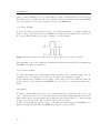
3-Wire-Master-Slave
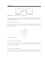
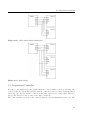
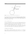
In the 3-Wire-Master-Slave configuration, as shown in Figure 2.15, only three wires are required,
because only one slave is connected to the bus. In this case the SS pin can be set fix to HIGH
level and therefore the SS wire is not needed. But some devices requires a falling edge of the
SS line to start interaction and in this cases the SS line is still needed.
Figure 2.15: 3-Wired-Master-Slave
4-Wire-Single-Master-Multi-Slave
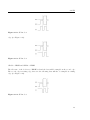
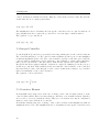
The 4-Wire-Single-Master-Multi-Slave configuration is shown in Figure 2.16 and is the mostly
used configuration of a SPI bus. Each slave has an independent SS wire connected to the
master, but shares the MOSI, MISO and SCK wire. As a result the slaves must have tri-state
outputs.
Daisy-Chain
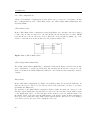
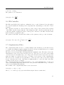
In the daisy-chain configuration (see Figure 2.17) all slaves share the SS and the SCK wire. In
this case all devices connected to the bus are active at the same time, but they do not share
the MOSI and MISO wire.
The structure of the Daisy-Chain configuration is like a chain: the master is connected to the
first slave via the MOSI wire, the first slave is connected to the next slave via the MISO output
to the MOSI input and so on. The last slave in the chain is connected with the master, via
the MOSI output of the slave and the MISO input of the master, again. In this configuration,
all devices act together like a large shift register, that means the data bytes received during a
cycle will be send to the next device during the next cycle.
20