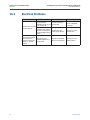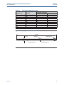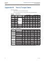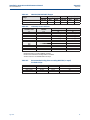
1
1-800-899-0553 assuredautomation.com F Series Rack and Pinion Pneumatic Valve Actuators USER’S MANUAL Installation, Operation, & Maintenance Assured Automation • 19 Walnut Avenue, CLark, New Jersey 07066 • Tel: 732-381-2255 • Fax: 732-381-2383 Assured Automation F Series DOC.IOM.EF.EN Rev. 2 Contents May 2014 Table of Contents Section 1: 1.1 1.2 1.3 Section 2: 2.1 2.2 2.3 Section 3: 3.1 Section 4: 4.1 4.2 4.3 4.4 4.5 4.6 4.7 Section 5: 5.1 Section 6: 6.1 6.2 Table of Contents Before You Start Installation, Operation and Maintenance Reference Documents ................ 1 Warehouse Storage ................................................................................... 1 On-Site Storage ......................................................................................... 2 Introduction *EFOUJ»DBUJPO ............................................................................................. 3 Intended Use ............................................................................................. 4 4QFDJ»DBUJPOT ............................................................................................ 4 Product Code $PO»HVSBUJPODPEFGPSBEFGBVMUBDUVBUPS .................................................. 6 Installation Before You Start ......................................................................................... 7 Failure Modes ............................................................................................ 7 4.2.1 Valve Rotation .............................................................................. 7 4.2.2 Position After Failure ..................................................................... 8 Principles of Operation............................................................................... 8 4.3.1 Solenoid Valve .............................................................................. 8 4.3.2 Ingress Protection (IP) rating ........................................................ 9 4.3.3 Double-Acting Actuators ............................................................ 10 4.3.4 Spring-Return Actuators ............................................................. 11 Actuator Assembly Codes ........................................................................ 12 Actuator to Valve Installation ................................................................... 13 Mounting of control and feedback accessories ......................................... 15 Recommended Tubing Sizes .................................................................... 16 Mechanical Stroke Adjustment Travel Stop Adjustment ............................................................................ 18 5.1.1 Double-Acting Actuators ............................................................ 18 5.1.2 Spring-Return Actuators ............................................................. 18 5.1.3 Angular Displacement ................................................................ 19 Maintenance General .................................................................................................... 20 Repair ...................................................................................................... 20 6.2.1 Spring-Return actuator ............................................................... 20 6.2.2 Recommended Spare Parts ......................................................... 20 I Assured Automation F Series Contents DOC.IOM.EF.EN Rev. 2 Section 7: Decommission (Out of Service) 7.1 7.2 Section 8: Before You Start ....................................................................................... 21 Removing the actuator from the valve ..................................................... 22 Disassembly 8.1 8.2 8.3 8.4 8.5 8.6 Section 9: May 2014 Removing End Caps ................................................................................. 24 Removing Spring Cartridges (Spring-Return) ........................................... 25 Removing of Limit Stop ........................................................................... 26 Removing Pistons .................................................................................... 26 Removing Pinion ...................................................................................... 27 Cleaning the Body .................................................................................... 27 Reassembly 9.1 9.2 9.3 9.4 9.5 9.6 Grease Instructions .................................................................................. 29 Reassembly of the pinion ......................................................................... 30 Reassembly of the pistons ........................................................................ 31 Reassembly and settings of the limit stops ............................................... 33 Reassembly of the end caps ..................................................................... 33 9.5.1 Double-Acting actuators ............................................................ 33 9.5.2 Spring-Return actuators ............................................................. 35 Basic function and Air Leak Test ............................................................... 37 Section 10: Troubleshooting 10.1 10.2 10.3 Mechanical Problems ............................................................................... 38 Pneumatic Problems ................................................................................ 39 Electrical Problems .................................................................................. 40 Section 11: Parts List and Spare Parts Recommendations 11.1 Appendix A: A.1 Appendix B: » » » » » II Exploded View and Parts List .................................................................... 41 Spring load removal Spring load relief ................................................................................. 42 Tool & Torque Table Table B-1 End cap bolts ...................................................................... 44 Table B-2 Bottom Flange .................................................................... 44 5BCMF#/".637%&7%* ¼BOHFT ......................................... 45 Table B-4 Limit stop dimensions ......................................................... 45 Table B-5 Recommended circlip pliers ................................................. 45 Table of Contents Installation, Operation and Maintenance Manual DOC.IOM.EF.EN Rev. 2 Section 1: Before You Start May 2014 Section 1: Before You Start This section explains: Base safety procedures 8IFSFUP»OEEFUBJMFEJOGPSNBUJPOSFMBUJOHTBGFUZ Storage guidelines. Installation, adjustment, putting into service, use, assembly, disassembly and maintenance PGUIFQOFVNBUJDBDUVBUPSNVTUCFQFSGPSNFECZRVBMJ»FEQFSTPOOFM NOTICE Failure to follow the above guidelines will void warranty. WARNING Actuator must be isolated both pneumatically and electrically before any (dis)assembly starts. Before mounting or (dis)assembly, the actuator consult the relevant sections of this manual. 1.1 Installation, Operation and Maintenance Reference Documents Before you start, read the following documents: All chapters in this manual. Safety Guide (Document No. DOC.SG.EF.EN). NOTICE Failure to read the Safety Guide will void the warranty. Not following the instructions of the Safety Guide can lead to failure of the product and harm to personnel or equipment. 1.2 Before You Start Warehouse Storage All actuators should be stored in a clean, dry warehouse, free from excessive vibration and rapid temperature changes. "MMBDUVBUPSTTIPVMEOPUCFTUPSFEEJSFDUMZUPUIF¼PPSTVSGBDFJUNVTUCFQMBDFEJO racks/shelves or use a pallet. 1 Section 1: Before You Start May 2014 1.3 Installation, Operation and Maintenance Manual DOC.IOM.EF.EN Rev. 2 On-Site Storage All actuators should be stored in a clean, dry warehouse, free from excessive vibration and rapid temperature changes. Prevent moisture or dirt from entering the actuator. Plug or seal both air connection ports. NOTICE Failure to follow the above guidelines (Warehouse and On Site Storages) will void warranty. 2 Before You Start Installation, Operation and Maintnance Manual Section 2: Introduction DOC.IOM.EF.EN Rev. 2 May 2014 Section 2: Introduction This section explains: 2.1 How to identify the received product, The intended use of the product Construction details "DUVBUPSTQFDJ»DBUJPOT Identification The Assured Automation F Series Rack and Pinion actuators are available as doubleacting or spring-return versions. 13 models are available, ranging from 12 Nm to 4000 Nm (106 to 35000 lbf.in) nominal torque output. The Assured Automation F Series uses standardized interfaces for solenoid, switchbox or positioner mounting (VDI/VDE3845; NAMUR). The valve interface is equipped with an insert in the pinion bottom that allows both ISO5211 or DIN3337 mounting. The springs in the spring-return version allow a fail action in case of loss of air supply pressure (Fail-to-Close or Fail-to-Open). "TGSPNTJ[F'%EPVCMFBDUJOHWFSTJPOTIBWF¼BUFOEDBQTUPSFEVDFBDUVBUPSMFOHUI and internal air volume. Figure 1 Identification 1 4 6 5 7 2 3 1. Top auxilliaries interface (VDI/VDE 3845; NAMUR) 2. Solenoid interface (VDI/VDE 3845; NAMUR) 3. Valve interface with ISO5211, DIN 3337 patterns and insert drive 4. Spring-return actuators: - with springs 5. Double-acting actuators: - no springs 6. High end caps for double-acting and spring-return models up to size 100 7. Low end caps for double-acting models as from size 150 and larger Introduction 3 Section 2: Introduction Installation, Operation and Maintenance Manual May 2014 2.2 DOC.IOM.EF.EN Rev. 2 Intended Use The Assured Automation F Series Rack and Pinion actuators are intended for the automation and operation PGRVBSUFSUVSOWBMWFTMJLF#VUUFS¼Z#BMMBOE1MVHWBMWFT Rack and Pinion actuators can also be used to operate dampers or any other quarter-turn applications. 2.3 Specifications Table 1. Pressure Range Actuator Type Pressure Double-Acting 0.2 to 8.3 barg (2.9 to 120 psig) 6 to 8.3 barg (87 to 120 psig), with maximum spring set 3 to 8.3 barg (43.5 to 120 psig), reduced spring quantity Spring-Return Table 2. Actuator Type Operating Media Double-Acting and Single-Acting Air, dry or lubricated and inert gases Dew point at least 10K below ambient temperature For sub-zero applications, take appropriate measures Mentioned pressure levels are "gauge pressures". Gauge pressure is equal to absolute pressure minus atmospheric pressure. Table 3. 4 Operating Media Temperature Range Actuator Type Temperature Standard Option: Low Temperature Option: High Temperature -20°C to +80°C (-4°F to +176°F) -40°C to +80°C (-40°F to +176°F) -20°C to +120°C (-4°F to +248°F) Introduction Installation, Operation and Maintenance Manual Section 2: Introduction DOC.IOM.EF.EN Rev. 2 May 2014 Table 4. Air Volumes and Consumption Actuator volumes: Maximum volume (in liters) Actuator Central1 End cap2 Displaced3 size chamber chamber volume 12 25 40 65 100 150 200 350 600 950 1600 2500 4000 0.05 0.11 0.16 0.36 0.4 0.8 0.8 1.9 3.1 5.1 7.8 10.4 18.4 0.06 0.19 0.36 0.55 0.8 0.7 1.0 1.7 2.9 4.3 7.0 11.1 18.9 0.04 0.08 0.15 0.22 0.3 0.5 0.7 1.2 2.1 3.2 5.2 8.2 14.0 Actuator volumes: Maximum volume (Cu.in.) Actuator Central1 End cap2 Displaced3 size chamber chamber volume 12 25 40 65 100 150 200 350 600 950 1600 2500 4000 3.1 6.4 10.0 22 22 48 50 118 189 310 477 638 1122 3.7 11.8 22 34 50 43 59 103 174 260 430 676 1151 2.5 4.7 8.9 13.5 19.9 32 44 76 129 193 319 501 853 Consumption per stoke (in liters, pressure in barg) Outward Stroke Inward Stroke Double-Acting Double-Acting only and Spring-Return 2 4 8 2 4 8 0.14 0.24 0.4 0.16 0.28 0.5 0.29 0.50 0.9 0.46 0.85 1.6 0.47 0.8 1.5 0.87 1.6 3.0 0.9 1.6 3.1 1.3 2.4 4.6 1.0 1.7 3.2 2.0 3.6 6.9 2.1 3.6 6.8 1.9 3.4 6.2 2.4 4.0 7.3 2.7 4.6 8 5.1 9 17 5 8 15 8 14 27 8 14 25 13 23 44 12 20 37 21 36 68 19 33 62 29 50 92 30 53 97 51 87 161 52 89 165 Consumption per stoke (in Cu.in., pressure in psig) Outward Stroke Inward Stroke Double-Acting Double-Acting only and Spring-Return 2 4 8 2 4 8 11 19 28 13 23 33 23 40 58 37 70 102 36 64 92 70 131 192 74 134 194 107 200 293 80 140 200 158 295 433 163 295 427 151 270 389 182 320 458 207 369 532 402 729 1055 359 642 925 650 1171 1692 610 1091 1571 1049 1905 2760 910 1628 2346 1635 2951 4267 1505 2691 3877 2259 4018 5776 2367 4232 6097 3946 7040 10134 4027 7202 10377 1. For Double-Acting and Spring-Return. Pistons at 90° outward position 2. Only for Double-Acting. Pistons at 0° inward position 3. Stroke is 90° Figure 2 Actuator air volumes Central air chamber volume Double-Acting and Spring-Return Introduction A End cap air chamber volume Double-Acting only B 5 Section 3: Product Code Installation, Operation and Maintenance Manual May 2014 DOC.IOM.EF.EN Rev. 2 Section 3: Product Code This section explains: )PXUPDSFBUFUIFDPO»HVSBUJPODPEFGPSBEFGBVMUBDUVBUPS )PXUPDSFBUFUIFDPO»HVSBUJPODPEFGPSBOBDUVBUPSXJUIBEEFEJOUFHSBMPQUJPOT FS 0150 U 40 CW AL T NL17 S K A 00 XX Internal code 2 Internal code 1 $PMPS»OJTI Visual indicator Temperature Valve stem connection Valve interface Pinion material Rotation Spring set Threads Size Type Type: FD FS Double-Acting Spring-Return Size: Body sizes: 0012, 0025, 0040, 0065, 0100, 0150, 0200, 0350, 0600, 0950, 1600, 2500 and 4000 Threads: M U Metric - ISO 5211 Imperial - ISO 5211 (UNC/NPT) Spring set: 00 For Double-Acting (no springs) 10, 20, 30, 40, For Spring-Return 50 or 60 Rotation: CW Spring to Close / Clockwise CC Spring to Open / Counterclockwise Pinion material: AL Aluminium, hard anodized Valve Interface: T Standard ISO 5211 - interface S Small interface with center plate DIN 3337 L Large interface with center plate DIN 3337 Valve Stem connection (Insert Sizes): 0000 No Insert Parallel drive: Diagonal drive : NL11 NL14 YD11 YD14 NL19 YD17 NL22 YD22 NL27 YD22 NL27 NL36 NL46 NL55 YD27 YD36 YD46 YD55 Square: 11 mm / 0.433" 14 mm / 0.551" 17 mm / 0.669" 19 mm / 0.748" 22 mm / 0.866" 22 mm / 0.866" 27 mm / 1.063" 27 mm / 1.063" 36 mm / 1.417" 46 mm / 1.811" 55 mm / 2.165" Actuator size(s): 0025 0040 & 0065 0100 & 0150 0200 0350 0600 0950 1600 & 2500 4000 1. See data sheet EFG.05.01.EN for a more detailed overview of available inserts. 2. Drive insert designation is according to ISO 5211. Temperature Ranges: S Standard: H High Temperature: L Low Temperature -20°C to +80°C (-4°F to -176°F) -20°C to +120°C (-4°F to +248°F) -40°C to +80°C (-40°F to +176°F) Visual indicator: K Standard (knob style) N No Visual indicator Finish: A Standard coating C CSR coating Note: CSR coating not available for Size 2500 and 4000 Internal code 1: 00 Standard Internal code 2: XX Standard 6 Product Code Installation, Operation and Maintenance Manual Section 4: Installation DOC.IOM.EF.EN Rev. 2 May 2014 Section 4: Installation This section explains: 4.1 The "Failure Modes" of an actuator. In which position the actuator will end after a failure. Principles of operation: — Solenoid operation — Double acting and Spring return operation Assembly codes. Actuator to valve assembly. Before You Start SAFETY FIRST In case of an air or electrical failure, it is important to know the behavior of the actuator. Before mounting the actuator on a valve, consult the following sections below. 4.2 Failure Modes 4.2.1 Valve Rotation 'PSUIFGPMMPXJOHQBSBHSBQITXFBTTVNFUIBUWBMWFTSPUBUFBTJOEJDBUFEJO»HVSF Figure 3 Normal valve rotation The valve is closed after a clockwise rotation. Installation The valve is open after a counterclockwise rotation. 7 Section 4: Installation Installation, Operation and Maintenance Manual May 2014 4.2.2 DOC.IOM.EF.EN Rev. 2 Position After Failure The position of the actuator after a failure depends on the: 1. Principle of operation (see paragraph 4.3) 2. Assembly codes (see paragraph 4.4) 3. Kind of failure. Refer to the table below. Table 5. Position After Failure Principle of Operation Assembly Code CW Double-Acting Actuator CC CW Single-Acting (Spring-Return) Actuator CC Kind of Failure Position Pressure Signal Supply Voltage Pressure Signal Supply Voltage Pressure Signal Supply Voltage Pressure Signal Supply Voltage /PUEF»OFE Closed Closed /PUEF»OFE Open Open Closed Closed Closed Open Open Open 4.3 Principles of Operation 4.3.1 Solenoid Valve "MMBDUVBUPSTDBOCFFJUIFSQJQFEXJUITPMJEPS¼FYJCMFUVCJOHXJUIUIFTPMFOPJEWBMWF mounted remotely from the actuator or by mounting a VDI/VDE 3845 (NAMUR) designed solenoid valve DIRECTLY onto the NAMUR mounting pad on the side of the actuator Figure 4 Typical solenoid operation Spring-Return Operation A 8 Double-Acting Operation A B Installation Installation, Operation and Maintenance Manual Section 4: Installation DOC.IOM.EF.EN Rev. 2 May 2014 The table below represents the cycle time (operating time) per different Actuator sizes: Table 6. Operating Speed Cycle time in seconds Actuator size F 12 F 25 F 40 F 65 F 100 F 150 F 200 F 350 F 600 F 950 F 1600 F 2500 F 4000 Spring-Return Double-Acting A-port pressurized Spring stroke A-port pressurized B-port pressurized 0.4 0.5 0.6 0.7 0.8 1.0 1.3 1.9 3.2 4.6 6.9 9.0 15.4 0.4 0.4 0.5 0.5 0.6 0.8 0.9 1.3 1.9 3.2 4.8 6.3 10.8 0.4 0.5 0.6 0.6 0.8 0.9 1.0 1.4 2.2 3.9 5.9 7.8 13.3 0.4 0.4 0.5 0.6 0.7 0.8 1.0 1.5 2.2 3.6 4.8 7.9 13.0 0QFSBUJOHUJNFJTBWFSBHFXJUIBDUVBUPSVOEFSMPBEBOETPMFOPJEWBMWF»UUFE Test conditions: 4PMFOPJEXJUI¼PXDBQBDJUZ 2. Pipe diameter: 3. Medium: 4. Supply pressure: 5. Load: 6. Stroke: 7. Temperature: 4.3.2 N3/hr 6mm clean air 5.5 bar (80psi) with average load 90° Room temperature Ingress Protection (IP) rating Assured Automation F Series actuators are IP66/IP67 rated. In case of IP66 or IP67 requirements, take precautions that comply with the IP66/IP67 requirements to prevent moisture or dust from entering the actuator through the open air exhaust port(s), either directly on the actuator or at the exhaust ports of the connected solenoid valve. We recommend to connect tubing to the exhaust(s) and lead this into a dry and dust free area, or to use check valves in the exhaust. Installation 9 Section 4: Installation Installation, Operation and Maintenance Manual May 2014 4.3.3 DOC.IOM.EF.EN Rev. 2 Double-Acting Actuators The operating principle, as explained here, is applicable for actuators with assembly code CW (direct acting). Applying supply pressure to port A will move the pistons outward to the "Open" position of the valve. Applying supply pressure to port B will move the pistons inward to the "Close" position of the valve. For assembly codes CC, the operating principle is reversed (reverse acting). Figure 5 Double-Acting Operation Outward Stroke A AB Inward Stroke B A B 10 Installation Installation, Operation and Maintenance Manual Section 4: Installation DOC.IOM.EF.EN Rev. 2 4.3.4 May 2014 Spring-Return Actuators The operating principle, as explained here, is applicable for actuators with assembly code CW (direct acting). Applying supply pressure to port A will move the pistons outwards to the "Open" position of the valve. Venting the supply pressure from port A will cause the springs to move the pistons inwards to the "Close" position of the valve. For assembly codes CC, the operating principle is reversed (reverse acting). Figure 6 Stroke Movements Outward Stoke A AB Inward Stroke B Installation 11 Section 4: Installation Installation, Operation and Maintenance Manual May 2014 4.4 DOC.IOM.EF.EN Rev. 2 Actuator Assembly Codes Figure 7 Assembly Code - Double-Acting Assembly code: CW Assembly code: CC = Standard, Clockwise-to-Close rotation = Reverse, Counterclockwise-to-Open = Fail-to-Close = Fail-to-Open B A A B Pinion Pistons A B B A Pistons A = Rotation when central air chamber is pressurized. B = Rotation when end cap air chambers are pressurized. All views are from above. Pistons are shown in inward position. Figure 8 Assembly Code - Spring-Return Assembly code: CW Assembly code: CC = Standard, Clockwise-to-Close rotation = Reverse, Counterclockwise-to-Open = Fail-to-Close = Fail-to-Open B A A Pistons 12 B Pinion A B Spring Cartridge A B Pistons Installation Installation, Operation and Maintenance Manual Section 4: Installation DOC.IOM.EF.EN Rev. 2 4.5 May 2014 Actuator to Valve Installation WARNING - MOVING PARTS Actuator must be isolated pneumatically and electrically before any (dis)assembly starts. Stay away from moving parts to prevent serious injuries. When test cycling the actuator and valve assembly by applying pressure to the A or B port, be aware that there are moving parts like pinion top, actuator to valve coupling and the valve- blade, ball, plug, etc. NOTICE The actuator is designed to be installed, commissioned and maintained using generic tools like wrenches, Allen keys and screwdrivers. For the removal of inserts, a special extractor tool can be supplied on request. During assembly to the valve, do not hit with hammer on pinion top. This can damage the pinion top washer and cause premature failure. Before mounting the actuator on the valve or valve bracket, be sure that both the actuator and the valve are in the same closed or open position. Refer to appendix B, Tool and Torque tables, for using the right size tool Table 7. Tool Table Symbol Symbol Tool Wrench – All types and sizes. Metric and Imperial Phillips -H- screw driver for actuator sizes 0025 to 0600. Circlip Pliers Allen key for actuator size 0012 1. Remove handle nut, handle, lock washer, and etc. from the valve if required. 2. Visually check to make sure the valve is CLOSED. Figure 9 Installation Tool Valve handle removal 13 Section 4: Installation Installation, Operation and Maintenance Manual May 2014 3. DOC.IOM.EF.EN Rev. 2 When required, check if the insert drive (23) is mounted. If not, use a plastic mallet and tap slightly until the reducer square is in the required position. Be sure that the insert is mounted at 90° or 45°. It is possible to mount the insert turned 22.5°. This way the valve will not open or close the right way. Figure 10 Insert drive Installation 90° 90° Parallel square 45° 23 4. 90° Round with key way *OTUBMMUIFCSBDLFUUPUIFWBMWF¼BOHF5JHIUFOBMMCPMUTBOEOVUTBOEBQQMZUIF correct torque. Figure 11 14 Diagonal square Flat head Bracket Installation Installation Installation, Operation and Maintenance Manual Section 4: Installation DOC.IOM.EF.EN Rev. 2 May 2014 5. Install the actuator to the bracket. Tighten all bolts and apply the correct torque (refer to Table 8). Table 8. Bottom flange torque values Actuator Size 25 40. 65, 100 150, 200, 350 600 950, 1600, 2500, 4000 6. ISO Pattern 3 inner pattern 5 outer pattern 5 inner pattern 7 outer pattern 7 inner pattern F10 outer pattern F10 inner pattern F12 outer pattern M5 M6 M6 M8 M10 M10 M10 M12 Torque (Nm) Min. Max. 2.0 4.5 4.5 10.5 21.0 27.0 21.0 34.5 3.0 5.0 5.0 12.5 24.5 24.5 24.5 43.0 When required, mount or adjust the visual indicator (22). Figure 12 Indicator mounting "In Line mounting" "Across Line mounting" 22 4.6 Thread 22 Mounting of control and feedback accessories Solenoid valve and or switch boxes can now be mounted to the actuator. Check the instructions as shipped with these components for installation, operating and maintenance instructions. We recommend to test-cycle the complete assembly to check correct operation. Installation 15 Section 4: Installation Installation, Operation and Maintenance Manual May 2014 4.7 DOC.IOM.EF.EN Rev. 2 Recommended Tubing Sizes In case the solenoid valve is mounted remotely (i.e. in a central solenoid cabinet) and in PSEFSUPTVQQMZTVG»DJFOU¼PXPGBJSTVQQMZUPUIFBDUVBUPSUIFGPMMPXJOHUVCJOHTJ[FTBSF recommended. Table 9. Tubing Sizes Actuator size 25, 40, 65 100, 150, 200, 350, 600 950, 1600, 2500, 4000 16 Runs up to Runs over to 1.2 meters 4 feet 1.2 meters 4 feet 6 mm 1/4 inch 6 mm 1/4 inch 6 mm 1/4 inch 8 mm 5/16 inch 6 mm 1/4 inch 10 mm 3/8 inch Installation Installation, Operation and Maintenance Manual Section 4: Installation DOC.IOM.EF.EN Rev. 2 May 2014 Section 5: Mechanical Stroke Adjustment This section explains: What mechanical stroke adjustment is. What the factory settings are. How to adjust the travel stops. Assured Automation F Series actuator sizes 25 to 4000 have two stroke adjustment stops for adjusting accurately the stroke of the actuator/valve assembly in open and closed position. The smallest actuator, size F12, does not have limit stops. The factory setting of the stroke is 90°. Most quarter-turn valve applications will not require readjustment of these settings. If required the stroke can be adjusted by means of two-stroke adjustment bolts. Figure 13 Factory Setting Size 25 - 600 10° -5° 10° 90° Installation Limit Stop 2 Size 950 - 4000 -3° 90° 80° 80° 95° 93° Limit Stop 1 17 Section 5: Mechanical Stroke Installation, Operation and Maintenance Manual May 2014 5.1 DOC.IOM.EF.EN Rev. 2 Travel Stop Adjustment CAUTION - PRESSURIZED ACTUATOR Do not turn out the travel stops completely when the actuator is pressurized. When adjusting the travel stops and the actuator is still pressurized, the travel stops can be “shot” away when completely turned out. 5.1.1 Double-Acting Actuators 1. Operate valve/actuator assembly to the required "Closed" position. 2. Remove air supply. 3. Slacken locknut on the “closed” stop (2). Figure 14 Stop 2 Stop 1 5.1.2 4. Turn the “closed” stop clockwise to reduce or counterclockwise to increase the USBWFM$POTVMUDIBQUFSBOHVMBSEJTQMBDFNFOUPGUIFQJOJPO UPEF»OFIPX far the limit stop must be turned in or out. 5. Tighten the lock nut. 6. Connect air and cycle the actuator to check that the position is correct. If not repeat from 2. 7. Remove air supply. 8. For adjusting the open position repeat steps 1 to 7, but now for the open position and “open” stop (1). Spring-Return Actuators 1. Connect air supply to the A port. Actuator will move to the open position. 2. Slacken locknut (24) on the “closed” stop (2). Figure 15 Stop 1 18 Stop 2 Mechanical Stroke Installation, Operation and Maintenance Manual Section 5: Mechanical Stroke DOC.IOM.EF.EN Rev. 2 May 2014 3. Turn the “closed” stop clockwise to reduce or counterclockwise to increase the USBWFM$POTVMUDIBQUFSBOHVMBSEJTQMBDFNFOUPGUIFQJOJPO UPEF»OFIPX far the limit stop must be turned in or out. 4. Remove air supply. Actuator will move to the closed position. 5. Check whether the actuator valve assembly is in the required position. If not repeat steps 1 to 5. 6. Remove air supply. 7. For adjusting the open position repeat steps 1 to 6, but now for the open position and "open" stop (1). Table 10. Actuator size Thread 25 40 65 100 150 200 350 600 950 1600 2500 4000 M6 M8 M 10 M 10 M 10 M 12 M 16 M 20 1. 2. 3. 5.1.3 Limit stop dimensions Bolt Wrench size (mm) Nut wrench size (mm) 10 13 17 (16)* 17 (16)* 17 (16)* 19 (18)* 24 30 10 13 17 (16)* 17 (16)* 17 (16)* 19 (18)* 24 30 Default dimension according DIN933 standard. Dimensions in brackets according ISO4017 standard. Actuator size 12 is not available with limit stops. Angular Displacement #FMPXUBCMFJEFOUJ»FTQFSBDUVBUPSTJ[FXIBUUIFBOHVMBSEJTQMBDFNFOUPGUIFQJOJPOTJT when using the limit stop screws. — Turn the limit stop clockwise reduces the stroke — Turn the limit stop counterclockwise to increase the stroke Table 11. Angular Displacement Actuator size F 12 F 25 F 40 F 65 F 100 F 150 F 200 F 350 F 600 F 950 F 1600 F 2500 F 4000 Turns for 5° adjustment of the pinion: 360° revolution of limit stop screw will adjust Actuator size 12 is not available with limit stops 0.7 7.1° 0.8 6.3° 0.6 8.3° 0.7 7.1° 1.2 4.2° 1.0 5.0° 0.8 6.3° 0.8 6.3° NOTICE In case of air leakage over the limit stop bolts, turn the lock nut of the limit stop bolts tighter, until leakage stops. Mechanical Stroke 19 Section 6: Maintenance Installation, Operation and Maintenance Manual May 2014 DOC.IOM.EF.EN Rev. 2 Section 6: Maintenance This section explains: When and how to do maintenance. What to do when replacing springs. What the availability is of spare parts, action conversion kits and temperature conversion kits. WARNING Actuator must be isolated pneumatically and electrically before any (dis)assembly starts. Before mounting or (dis)assembling the actuator consult the relevant sections of this manual. 6.1 General Assured Automation F Series actuators are designed to operate without maintenance for their normal working life. Normal working life is 500,000 cycles.* We recommend regular inspections to make certain that the actuator / valve assembly operates smoothly and to check that there are no visible or audible defects. Replacement of internal seals and bearings allows to you extend the normal working life. Repair kits, containing all necessary seals bearings, grease and instructions can be obtained through authorized Emerson Process Management – Valve Automation distributors. "MMBDUVBUPSTBSFTVQQMJFEXJUITVG»DJFOUMVCSJDBUJPOGPSUIFJSOPSNBMXPSLJOHMJGF*G required, see section 9.1 (Grease instructions) for the recommended grease. For mounting the parts of the repair kit follow the instruction of the Decommission, Disassembly and Reassembly chapters of this manual. Note: *Cycles = one open stroke and one close stroke. 6.2 Repair 6.2.1 Spring-Return actuator On spring-return actuators, the spring cartridges can be replaced. SPRING CARTRIDGES SHOULD ALWAYS BE REPLACED IN COMPLETE SETS. Spring kits are available through authorized Emerson Process Management – Valve Automation distributors. 6.2.2 Recommended Spare Parts All soft seals, bearings, and nonreusable parts are included in the recommended spare parts kit. The spare parts kit is identical for both the double-acting and the spring-return models. For the spring-return models we recommend a set of spare springs for each different model in addition to the recommended spare parts kit. 20 Maintenance Installation, Operation and Maintenance Manual Section 7: Decommission (Out of Service) DOC.IOM.EF.EN Rev. 2 May 2014 Section 7: Decommission (Out of Service) This section explains: 7.1 How to decommission an actuator in a safe way. Before You Start WARNING - MOVING PARTS Actuator must be isolated pneumatically and electrically before any (dis)assembly starts. Before mounting or (dis)assembling the actuator consult the relevant sections of this manual. Actuator can move when removing supply pressure and/or electrical control signal of actuators. If not already there, a spring-return actuator will cycle to its fail position. When removing any ball valve or plug valve assemblies from a pipe system, isolate the piping system on which the Actuator is installed and relieve any media pressure that may be trapped in the valve cavities before removing the actuator for maintenance. A spring-return actuator mounted on a valve, which is stuck in mid stroke, contains a high spring load which will cause a sudden rotation of the actuator versus the valve or valve bracket during disassembly. This can cause serious injury to personnel or damage to property. Refer to Appendix A for instructions to safely remove the spring load before disassembling the spring-return actuator from valve or bracket. Important Refer to the Safety Guide for Lifting Instructions. Decommission 21 Installation, Operation and Maintenance Manual Section 7: Decommission (Out of Service) May 2014 7.2 DOC.IOM.EF.EN Rev. 2 Removing the actuator from the valve 1. Disconnect all air supply hoses (Ports A and B or solenoid). 2. Disconnect all electrical wirings of the switch box. 3. Disconnect the electrical wiring of the solenoid valve. 4. 3FNPWFUIFCPMUTBOEOVUTGSPNUIFWBMWF¼BOHF 5. Remove the bracket from the actuator. 6. Remove the switch box and solenoid valve. Refer to the documentation of the switch box and solenoid valve for safe disassembly. Figure 16 Removing actuator from valve 1 2 3 4 22 Decommission Installation, Operation and Maintenance Manual DOC.IOM.EF.EN Rev. 2 Section 8: Disassembly May 2014 Section 8: Disassembly This section explains: How to disassemble an actuator safely. Tip 5IFJOTUSVDUJPOTPGUIJTTFDUJPODBOCFVTFEGPSNBJOUFOBODFPSSFDPO»HVSBUJPOMJLFTQSJOH set change or maintenance. Reference numbers for components refer to the exploded view in section 11. In case of maintenance, discard all the used soft parts like O-ring seals, guide bands, wear strips and circlip. WARNING Actuator must be isolated pneumatically and electrically before any (dis)assembly starts. Before mounting or (dis)assembling the actuator consult the relevant sections of this manual. CAUTION - SPRING FORCE Spring-return actuators contain springs in a compressed state. Follow these instructions to release the spring force safely. Normally the end caps of spring-return actuators should be free of the spring load after 10 full turns (crosswise relaxing) of the end cap screws. If there is still spring load on the end cap, this might indicate a broken spring cartridge. Stop this disassembly procedure immediately. Continuing might cause the end cap to be “shot” away causing serious injury. Refer to Appendix A for instructions to safely remove the spring load before disassembling the end cap of a spring-return actuator with a broken spring cartridge. NOTICE The actuator is designed to be installed, commissioned and maintained using generic tools like wrenches, Allen keys and screwdrivers. Refer to the tables in this section or refer to appendix B Tool and Torque tables. Disassembly 23 Installation, Operation and Maintenance Manual Section 8: Disassembly May 2014 8.1 DOC.IOM.EF.EN Rev. 2 Removing End Caps 1. For Double-acting actuators, do the following: a. Loosen the screws (10) of the end caps (2). b. Remove the o-ring (14) and "B" port seal (16). Discard these parts. Figure 17 Double-Acting End Caps Removal 2 10 2 10 14 14 16 The above end caps (2) are for Actuator sizes 25, 40, 65 and 100. End caps (2) for Actuator sizes 150 and larger will have flat end caps (see below). 2 24 Disassembly Installation, Operation and Maintenance Manual Section 8: Disassembly DOC.IOM.EF.EN Rev. 2 May 2014 2. For Spring-return actuators, do the following: a. Tip: For actuators with assembly code CW, turn back the right hand limit stop screw (17) 2 full turns. For actuators with assembly code CC, turn back the left hand limit stop screw (17) 2 full turns. This will lower the spring force on the end cap and reduces the screw out length of the end cap screws. b. Important: Apply a strong, sudden rotational and downward force to loosen all the end cap screws (10) for maximum 1/4 turn. c. Uniformly loosen the screws (10) of the end caps (2) 1/4-1/2 turns at a UJNFJOTFRVFODFBTQFS»HVSFUPSFMJFWFUIFQSFMPBEPGUIFTQSJOHT d. Remove the o-rings (14) and "B" port seals (16). Discard these parts. Figure 18 Spring-Return End Caps Removal 17 2 10 2 10 3 2 14 14 1 4 8.2 16 Removing Spring Cartridges (Spring-Return) 1. Remove the spring cartridges (5). Figure 19 5 5 Disassembly 25 Installation, Operation and Maintenance Manual Section 8: Disassembly May 2014 8.3 DOC.IOM.EF.EN Rev. 2 Removing of Limit Stop 1. Remove the limit stop screws (17), limit stop nuts (18), limit stop washers (19) and limit stop o-rings (15). Discard the o-rings. Figure 20 Limit Stop Removal 15 8.4 19 18 17 Removing Pistons 1. Use a wrench and turn the pinion counterclockwise (180°) until the pistons (3) comes out of the body. 2. Remove the piston bearings (7), piston rack bearing strips (6) and piston o-ring seals (13). Discard these parts. Figure 21 Piston Removal 3 13 7 6 6 7 26 13 3 Disassembly Installation, Operation and Maintenance Manual Section 8: Disassembly DOC.IOM.EF.EN Rev. 2 8.5 May 2014 Removing pinion 1. Remove the circlip (11) and thrust washer (9) on top of the pinion assembly. Discard if necessary the circlip (11) and thrust washer (9). 2. Remove the pinion (4) by pushing it downwards. 3. Remove the pinion o-ring seals (12) and the pinion bearings (8). Discard all of these parts. Figure 22 Pinion Removal 8 11 9 Table 12. 12 8 4 Recommended circlip pliers according DIN 5254 (or equal) for shaft circlips. Actuator size 12 25 - 100 150 - 350 600 8.6 12 Pinion top diameter 16 mm 22 mm 36 mm 55 mm 0.630" 0.866" 1.417" 2.165" Pliers according DIN 5254 A1 A2 A3 A3 Cleaning the Body In case of maintenance, use a clean dry cloth and thoroughly wipe clean and remove old grease from: Disassembly The inside and outside of the body including thread holes and crevices/grooves The pinion gears The pistons 27 Installation, Operation and Maintenance Manual Section 9: Reassembly May 2014 DOC.IOM.EF.EN Rev. 2 Section 9: Reassembly This section explains: Which parts and how to grease them. How to reassemble a complete actuator. How to set the stroke adjustment bolts after reassembly. How to do a basic function and air leak test. Tip 5IFJOTUSVDUJPOTPGUIJTTFDUJPODBOCFVTFEGPSNBJOUFOBODFPSSFDPO»HVSBUJPOMJLFTQSJOH set change or maintenance. Reference numbers for components refer to the exploded view in section 11. In case of maintenance, discard all used soft parts like O-ring seals, guide bands and wear strips and circlip and replace them with the parts as supplied in the repair kit. *ODBTFPGSFDPO»HVSBUJPOSFQMBDFUIFQBSUTBTTVQQMJFEJOUIFDPOWFSTJPOLJUTFFBMTP chapter 6). Refer to the Safety Guide for Lifting Instructions. NOTICE The actuator is designed to be installed, commissioned and maintained using generic tools like wrenches, Allen keys and screwdrivers. Refer to the tables in this section or refer to appendix B Tool and Torque tables. 28 Reassembly Section 9: Reassembly Installation, Operation and Maintenance Manual DOC.IOM.EF.EN Rev. 2 9.1 May 2014 Grease Instructions $IFDLUIFQSPEVDUDPEJOHPOUIFQSPEVDUMBCFMTBOEDIBQUFSPGUIJTNBOVBMUPEF»OF which type of grease to use. - For standard actuators (-20°C to +80°C / -4°F to +176°F): Castrol High Temperature grease (or equivalent). - For low temperature operation (-40°C to +80°C / -40°F to +176°F): Castrol Optitemp TT1 grease (or equivalent). - For high temperature operation (-20°C to +120°C / -4°F to +248°F): Castrol High Temperature grease (or equivalent). We recommend using a suitable sized paint brush to apply the required amount of grease on the parts as per Table 12 and Figure 23. Table 13. Grease Instructions Part O-rings: A B C D E F G H J K L M N Housing Parts: Piston Parts: Piston Parts: Figure 23 Section of part Amount of grease Completely Piston bore Top pinion bore Bottom pinion bore O-ring & bearing groove Rack teeth Piston bearing Piston rack bearing strip Pinion bottom & O-ring groove Pinion top & O-ring groove Gear teeth Pinion top bearing Pinion bottom bearing -JHIU»MN -JHIU»MN -JHIU»MN -JHIU»MN -JHIU»MN Half the teeth depth full with grease -JHIU»MNPOPVUTJEF -JHIU»MN -JHIU»MN -JHIU»MN Half the teeth depth -JHIU»MNJOTJEFBOEPVU -JHIU»MNJOTJEFBOEPVU Grease Instructions A M K A L E J F C N G A A H A B Reassembly A D 29 Installation, Operation and Maintenance Manual Section 9: Reassembly May 2014 9.2 DOC.IOM.EF.EN Rev. 2 Reassembly of the pinion 1. Grease the pinion parts according to chapter 9.1. 2. Install the pinion bearings (8) and the O-ring seals (12) on the pinion (4). 3. Insert the pinion (4) on the housing. 4. Install the thrust washer (9) and mount the circlip (11) on the pinion top using circlip pliers. — Figure 24 1 Install the new circlip onto its mating groove on the top shaft extension and with the non-sharp edge (2) towards the housing and the sharp edge (1) towards the top of the shaft. Reassemble the pinion 2 8 11 Table 14. Actuator size 12 25 - 100 150 - 350 600 30 9 12 12 8 4 Recommended circlip pliers according DIN 5254 (or equal) for shaft circlips. Pinion top diameter 16 mm 22 mm 36 mm 55 mm 0.630" 0.866" 1.417" 2.165" Pliers according DIN 5254 A1 A2 A3 A3 Reassembly Section 9: Reassembly Installation, Operation and Maintenance Manual DOC.IOM.EF.EN Rev. 2 9.3 May 2014 Reassembly of the pistons NOTICE Before reassembling the pistons, check the required assembly code (see section 4.2). 1. Grease the piston parts according to step 9.1. 2. Install the piston bearings (7), piston rack bearing strips (6) and piston o-ring seals (13) on the pistons. Ensure all these parts are kept in place during assembly. Figure 25 Reassemble the pistons 3 13 7 6 6 7 3. 4. 5. 6. Reassembly 13 3 Align the pinion (see Figure 26) so that the teeth on the pinion will pick up the pistons rack teeth when turning the pinion. Note the position of the pinion top slot and the cam on the pinion top: — For standard or Spring-to-Close: Assembly Code CW — For reverse or Spring-to-Open: Assembly Code CC Slightly push the pinion inward to engage with the pinion. — Ensure that smooth movement and 90-degree operation can occur without moving the pistons out of the actuator body. — For larger pistons, use a rubber mallet and slightly hitting the pistons inward to engage with the pinion. 8IFOUIFQJTUPOTBSFNPWFEJOXBSETTFF»HVSF DIFDLUIBUUIFQJOJPOTMPU on the pinion top is: — Perpendicular to the length centre line of the house for assembly code CW. — In line to the length centre line of the house for assembly code CC. If not, turn pinion to move the pistons outward until they disengage from the pinion. Shift one tooth of the pinion, reassemble and check again. 31 Installation, Operation and Maintenance Manual Section 9: Reassembly May 2014 DOC.IOM.EF.EN Rev. 2 Figure 26 Position of the slot and the cam on the pinion top Assembly code CW (Standard; Spring-to-Close) A B Assembly code CW (Reverse; Spring-to-Open) A B 90° C 90° C A = Position of cam B = Position of slot and in dot in pinion C = Final position of pinion dot Note: When the pistons are completely moved inwards, the pinion top will show a 5° over travel. 32 Reassembly Section 9: Reassembly Installation, Operation and Maintenance Manual DOC.IOM.EF.EN Rev. 2 9.4 May 2014 Reassembly and settings of the limit stops 1. Install the limit stop screws (17), limit stop nuts (18), limit stop washers (19) and limit stop o-rings (15). Figure 27 Install Limit Stop Bolts 15 19 18 17 2. Move the pistons inward until the slot in the top of the pinion is perpendicular to centerline of the housing. 3. Double check if the position of the slot and the cam on the pinion top is in the DPSSFDUQPTJUJPOTFF»HVSF 4DSFXJOUIFSJHIUIBOEUSBWFMTUPQVOUJMJUDPNFT into contact with the pinion stop face. 4. Move the pistons outward until the slot in the top of the pinion is in line with the centerline of the housing. 5. Screw in the left hand travel stop until it comes into contact with the pinion stop face. — For accurate travel stop adjustment of the actuator on the valve, see section 5. 9.5 Reassembly of the end caps 9.5.1 Double-Acting actuators Reassembly 1. Grease the O-ring seals (14) and B port seals (16) according to step 9.1. 2. Ensure that O-ring seals (14) and B port seals (16) are kept in place during assembly. 3. Install the end caps (2) and tighten the end cap screws (10). Refer to Table 14 for the correct torque. 33 Installation, Operation and Maintenance Manual Section 9: Reassembly May 2014 DOC.IOM.EF.EN Rev. 2 Figure 28 Double-acting end cap assembly 2 10 2 10 14 14 16 The above end caps (2) are for Actuator sizes 25, 40, 65 and 100. End caps (2) for Actuator sizes 150 and larger will have flat end caps (see below). 2 Table 15. End cap Screw Torque Actuator Thread size 12 25 40 65 100 150 200 350 600 950 1600 2500 4000 34 M4 M5 M5 M5 M5 M6 M6 M8 M10 Tool Size Allen key SW 3 No. 2 No. 2 No. 2 No. 2 No. 3 No. 3 No. 4 No. 4 Phillips -HScrewdriver Torque (Nm) Torque (lbf.ft) Target Min. Max. Target Min. Max. 1.1 2.0 2.0 2.0 2.0 3.3 3.3 8.4 15.3 0.8 1.6 1.6 1.6 1.6 2.6 2.6 6.7 12.2 1.3 3.0 3.0 3.0 3.0 5.1 5.1 12.2 24.8 0.8 1.5 1.5 1.5 1.5 2.4 2.4 6.2 11.3 0.6 1.2 1.2 1.2 1.2 1.9 1.9 4.9 9.0 1.0 2.2 2.2 2.2 2.2 3.8 3.8 9.0 18.3 Reassembly Section 9: Reassembly Installation, Operation and Maintenance Manual DOC.IOM.EF.EN Rev. 2 9.5.2 May 2014 Spring-Return actuators Important When replacing spring cartridges in a spring-return actuator, ensure that the cartridges are replaced in their identical position from where they were removed. $IFDLCFMPX»HVSFUPTFFXIFSFUPQMBDFUIFTQSJOHDBSUSJEHFTJODBTFPGTQSJOHTFU conversion. Before assembling the spring cartridges and end caps, make sure that the pistons are completely inwards. Figure 29 Spring cartridge placement 6 4 6 5 5 N=50 2 4 5 N=30 1 6 3 2 1 4 3 6 4 3 3 2 1 4 5 1 2 N=40 N=20 5 1 N=10 6 3 B 2 5 2 1 4 3 6 A N=60 A = Piston top view B = Position of gear rack Reassembly 35 Installation, Operation and Maintenance Manual Section 9: Reassembly May 2014 DOC.IOM.EF.EN Rev. 2 1. Grease the O-ring seals (14) and B port seals (16) according to step 9.1. 2. Ensure that O-ring seals (14) and B port seals are kept in place during assembly. 3. Place the spring cartridges in actuator as per required spring set (see Figure 29). 4. Tighten each end cap screw in small equal turns and in the sequence as per Figure 28. Refer to Table 13 for the correct torque. We recommend to use some grease on the screws for easier fastening. Figure 30 Spring-return end cap assembly 2 10 2 10 3 2 14 14 1 4 36 16 Reassembly Section 9: Reassembly Installation, Operation and Maintenance Manual DOC.IOM.EF.EN Rev. 2 9.6 May 2014 Basic function and Air Leak Test CAUTION - MOVING PARTS Applying pressure to the actuator will cause the actuator/valve assembly to operate. 1. Apply pressure (max. 8 bar/116 psi) to ports A and B. Use some soap suds at the indicated points: around pinion top (1), pinion bottom (2), the end caps (3) and limit stops (4). 2. In case of leakage around: a. The limit stop bolts (and/or the spring-package bolt at spring-return models). Turn the lock nut of the bolts tighter; until the leakage stops. b. The end caps: Disassemble the end caps, replace o-rings and reassemble. c. The pinion top or bottom and A- or B- port: Disassemble the complete actuator, replace o-rings and reassemble. Figure 31 Basic function and air leak test 1 3 4 A B 3 B A Reassembly 2 37 Section 10: Troubleshooting Installation, Operation and Maintenance Manual May 2014 Section 10: 10.1 DOC.IOM.EF.EN Rev. 2 Troubleshooting Mechanical Problems Problem Feedback position and actual position are not the same Valve is in “Closed” position, actuator is in “Open” position and will not move anymore. Valve does not reach the completely “Closed” or “Open” position. Actuator rotates, valve does not. 38 Possible error Solution Actuator and valve are mounted 90° rotated in relation to each other. Remove actuator from valve. Check assembly code of actuator. Put Section 4 both valve and actuator in “Closed” position. Mount actuator on valve. Limit stop screws are not Readjust the limit stop set correctly. screws. Mount the insert in the right position. Insert is not mounted properly. Remark: Rotate insert to one cam = 22.5°. Apply pressure as per Pressure too low. sizing. Check valve torque data Sizing is wrong. with actuator torque data. Pinion is mounted in the Reassemble actuator. wrong position No coupling between Install a coupling actuator shaft and valve between actuator shaft spindle. and valve spindle. Where to find Section 5 Section 4.5 Section 9 Section 4.5 Troubleshooting Section 10: Troubleshooting Installation, Operation and Maintenance Manual DOC.IOM.EF.EN Rev. 2 10.2 May 2014 Pneumatic Problems Problem Possible error Actuator does not react There is no supply to electrical control pressure at the signal. actuator. 5IFSFJTTVG»DJFOU supply air pressure but JOTVG»DJFOUTVQQMZBJS capacity. Solution Where to find Supply the right pressure to the actuator. Section 2.3 Check that the actual supply pressure is higher than the sizing pressure. Take care the supply air tubing has the right dimensions. Section 4.6 Check that supply Supply pressure too pressure at the low, causing pilot actuator and solenoid operated solenoid valve JTTVG»DJFOUUPPQFSBUF to fail. Actuator does not the actuator. react good to electrical Solenoid valve is not Check the solenoid control signal. mounted properly. valve mounting. Speed control throttle Turn the speed control (if present) blocks air more open. ¼PX Manual override Unlock manual override on the solenoid valve. (if present) on the Solenoid Valve is locked. Air leakage between Sealing between Reassemble solenoid actuator and solenoid solenoid valve and valve taking care, that valve. actuator is not all seals are in place. mounted air tight. Double-acting actuator Actuator has wrong will only move to solenoid valve “open” position. DPO»HVSBUJPO Troubleshooting Section 2.3 Check that the actual supply pressure is higher than the sizing pressure. Instructions shipped with the solenoid valve. Instructions shipped with the speed control valve. Instructions shipped with the manual override. Instructions shipped with the solenoid valve. Mount a solenoid valve suitable for doubleInstructions shipped acting actuators with the solenoid valve. (4/2 or 5/2 function). Check that conversion plate on solenoids, that Instructions shipped have both 3/2 and 5/2 with the solenoid valve. functions, is in the right position. 39 Section 10: Troubleshooting Installation, Operation and Maintenance Manual May 2014 10.3 DOC.IOM.EF.EN Rev. 2 Electrical Problems Problem Possible error Control wiring. Power supply wiring or feedback wiring are not right connected. Actuator does not react The power supply to control signals. voltage is not is not the same as the voltage of the applicable solenoid valve. There are problems with position feedback The wiring of the after sending the feedback signals may actuator to either the be switched. “Open” or “Closed” position. 40 Solution Where to find Connect all wiring in the right way. Instructions of the control or feedback accessories. Connect the right power supply voltage. Instructions of the solenoid valve. Connect the feedback wiring in the right way. Instructions of the feedback device. Troubleshooting Installation, Operation and Maintenance Manual Section 11: Parts List and Spare Parts DOC.IOM.EF.EN Rev. 2 May 2014 Section 11: 11.1 Parts List and Spare Parts Recommendations Exploded View and Parts List 21 15 19 1 11 9 4 13 7 3 5 14 2 10 20 18 17 6 22 8 16 12 23 Table 16. Parts List Pos. Qty 1 2 3 4 5 6 7 8 9 10 11 12 13 14 15 16 17 18 19 20 21 22 23 1 2 2 2 Max. 12 2 2 2 1 8 1 2 2 2 2 2 2 2 2 2 1 1 1 * * * * * * * * * * Description Material House End cap Piston Pinion Spring cartridge Bearing strip piston rack Bearing piston Bearing pinion Thrust washer End cap screw Circlip O-ring seal pinion O-ring seal piston O-ring seal end cap O-ring seal limit stop B-port seal Limit stop screw Limit stop nut Limit stop washer Warning sticker Indicator assembly Center plate (option) Insert drive Cast Aluminium alloy Cast Aluminium alloy Cast Aluminium alloy High grade aluminium Spring steel POM 15'&DBSCPO»MMFE POM POM, black UV stabilized Stainless Steel Spring steel Nitrile rubber Nitrile rubber Nitrile rubber Nitrile rubber Silicon rubber Stainless steel Stainless steel PA66 Polyester ABS + stainless steel screw Nylon PA6, Black Aluminium * = included in repair kit Parts List and Spare Parts 41 Appendix Installation, Operation and Maintenance Manual May 2014 DOC.IOM.EF.EN Rev. 2 Appendix A: Spring load removal This section explains: How to remove the spring load safely of spring-return actuators in case: — The valve gets “stuck” in mid position. — One of the spring cartridges is broken. WARNING - MOVING PARTS A spring-return actuator mounted on a valve, which is stuck in mid stroke, contains a high spring load which will cause a sudden rotation of the actuator versus the valve during disassembly. This can cause serious injury to personnel or damage to material. On spring-return actuators with a broken spring cartridge, the end cap can be “shot” away during disassembly of the actuator. This can cause serious injury to personnel or damage to material. A.1 Spring load relief CAUTION - ROTATING ACTUATOR In case of an actuator/valve assembly “stuck” in mid position, leave the actuator on the valve and/or mounting bracket during this procedure. Figure A-1 Spring load removal WARNING Crush / Amputaion Hazard Failure to follow instructions for removal of spring loaded actuator may result in surious personal injury 42 1. Depressurize the actuator completely. 2. Based on the actuator size, choose the correct threaded rod kit from Table A-1. 3. Replace one by one each end cap screw for the threaded rod kit and turn down the adjusting nut until it touches the end cap. 4. Once all for end cap screws have been replaced, gradually turn the adjustment nuts on threaded rod in CCW direction by turning the nuts half turn at a time. Make sure the rod itself does not turn. Continue this until the load of springs are relieved. 5. Repeat the same procedure for the end cap screws on the other size of the BDUVBUPSBTTIPXOJO»HVSF" 6. In case of an actuator/valve assembly “stuck” in mid position: The actuator now can be disassembled from Valve, by removing the mounting studs/bolts. Appendix Installation, Operation and Maintenance Manual Appendix DOC.IOM.EF.EN Rev. 2 May 2014 Table A-1. Threaded rod dimensions in mm Actuator Size Thread 12 25 40 65 100 150 200 350 600 950 1600 2500 4000 M4 M5 M5 M5 M5 M6 M6 M8 M10 Figure A-2 Threaded rod length (mm) (inch) 132 140 140 140 140 145 145 185 185 5.2 5.5 5.5 5.5 5.5 5.7 5.7 7.3 7.3 Spring load removal rod dimensions Length Thread Washer Threaded Rod Appendix Holding nuts Adjusting nut 43 Appendix Installation, Operation and Maintenance Manual May 2014 DOC.IOM.EF.EN Rev. 2 Appendix B: Tool & Torque Table This section explains: Which tools to use for the indicated fasteners The recommended amount of torque to apply on the indicated fasteners. Table B-1. End cap bolts Actuator Thread size 12 25 40 65 100 150 200 350 600 950 1600 2500 4000 M4 M5 M5 M5 M5 M6 M6 M8 M10 Tool Size Allen key SW 3 No. 2 No. 2 No. 2 No. 2 No. 3 No. 3 No. 4 No. 4 Phillips -HScrewdriver Table B-2. Bottom flange Actuator size ISO Pattern 12 4 3 inner pattern 25 5 outer pattern 5 inner pattern 40, 65, 100 7 outer pattern 7 inner pattern 150, 200, 350 F10 outer pattern F10 inner pattern 600 F12 outer pattern F10 inner pattern 950 F14 outer pattern F16 inner pattern 1600 F251 outer pattern F16 inner pattern 2500 F251 outer pattern F16 inner pattern 4000 F25 outer pattern Metric Thread M6 M5 M6 M6 M8 M8 M10 M10 M12 M10 M16 M20 M16 M20 M16 M20 M16 Torque (Nm) Torque (lbf.ft) Target Min. Max. Target Min. Max. 1.1 2.0 2.0 2.0 2.0 3.3 3.3 8.4 15.3 0.8 1.6 1.6 1.6 1.6 2.6 2.6 6.7 12.2 1.3 3.0 3.0 3.0 3.0 5.1 5.1 12.2 24.8 0.8 1.5 1.5 1.5 1.5 2.4 2.4 6.2 11.3 0.6 1.2 1.2 1.2 1.2 1.9 1.9 4.9 9.0 1.0 2.2 2.2 2.2 2.2 3.8 3.8 9.0 18.3 Torque (Nm) Min. Max. Imperial Thread Torque (lbf.ft) Min. Max. 4.5 2.0 4.5 4.5 10.5 10.5 21.0 21.0 34.5 10-24UNC 10-24UNC 1/4"-20 1/4"-20 5/16"-18 5/16"-18 3/8"-16 3/8"-16 1/2"-13 3/8"-16 5/8"-11 3/4"-10 5/8"-11 3/4"-10 5/8"-11 3/4"-10 5/8"-11 3.3 1.5 3.3 3.3 7.7 7.7 15.5 15.5 25.4 5.0 3.0 5.0 5.0 12.5 12.5 24.5 24.5 43.0 3.7 2.2 3.7 3.7 9.2 9.2 18.1 18.1 31.7 1. For actuator sizes 1600 and 2500 only 4 holes of the ISO5211 F25 drilling pattern are available. 44 Appendix Installation, Operation and Maintenance Manual Appendix DOC.IOM.EF.EN Rev. 2 May 2014 Table B-3. NAMUR (VDE/VDI 3845) flanges Metric Thread Flange Torque (Nm) Min. Max. Imperial Thread Torque (lbf.ft) Min. Max. 4PMFOPJE¼BOHFTDSFXUISFBET M5 2.0 3.0 10-24UNC 1.5 2.2 5PQ¼BOHFTDSFXUISFBET M5 2.0 3.0 10-24UNC 1.5 2.2 Table B-4. Limit stop screws and nuts Actuator size Thread Bolt Wrench size (mm) Nut wrench size (mm) 25 40 65 100 150 200 350 600 950 1600 2500 4000 M6 M8 M 10 M 10 M 10 M 12 M 16 M 20 10 13 17 (16)1 17 (16)1 17 (16)1 19 (18)1 24 30 10 13 17 (16)1 17 (16)1 17 (16)1 19 (18)1 24 30 Default dimension according DIN933 standard Dimensions in brackets according ISO4017 standard Actuator size 12 is not available with limit stops Table B-5. Recommended circlip pliers according DIN 5254 (or equal) for shaft circlips Actuator size F12 F25 - F100 F150 - F350 F600 Appendix Pinion top diameter 16 mm 22 mm 36 mm 55 mm 0.630" 0.866" 1.417" 2.165" Pliers according DIN 5254 A1 A2 A3 A3 45