1
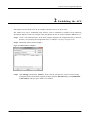
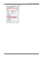
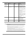
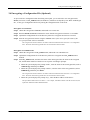
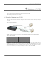
Auto provision Configuration Manual New Rock Technologies, Inc. Auto Provisioning Configuration Manual Website: http://www.newrocktech.com Email: [email protected] Auto provision Configuration Manual Amendment Records Document Rev. 03 (Sep, 2015 ) Document Rev. 02 (Nov, 2014 ) Document Rev. 01 (Jun, 2014 ) Copyright © 2015 New Rock Technologies, Inc. All Rights Reserved. All or part of this document may not be excerpted, reproduced and transmitted in any form or by any means without prior written permission from the company. New Rock Technologies, Inc. 1 Auto provision Configuration Manual Contents Amendment Records .............................................................................................................................................................................1 Contents..................................................................................................................................................................................................2 Contents of Figure .................................................................................................................................................................................3 Contents of Table ...................................................................................................................................................................................4 1 Overview..............................................................................................................................................................................................5 1.1 Definition .................................................................................................................................................................................5 1.2 How Auto-Provision Works .....................................................................................................................................................6 2 Establishing the ACS ..........................................................................................................................................................................8 3 Preparing Configuration Files .........................................................................................................................................................10 3.1 Configuration Files .................................................................................................................................................................10 3.1.1 General Configuration File.........................................................................................................................................10 3.1.2 MAC-addressed File ..................................................................................................................................................10 3.2 Common Configuration Parameters .......................................................................................................................................11 3.3 Editing Configuration Files ....................................................................................................................................................19 3.4 Encrypting a Configuration File (Optional)............................................................................................................................22 4 Obtaining an ACS URL ...................................................................................................................................................................24 4.1 Manually Configuring the ACS URL .....................................................................................................................................24 4.2 Obtaining an ACS URL via DHCP option 66 ........................................................................................................................27 4.3 Obtaining an ACS URL via Redirection Mechanism .............................................................................................................31 Appendix 1: Operation Instance ........................................................................................................................................................33 Appendix 2: Configuration File Template .........................................................................................................................................35 New Rock Technologies, Inc. 2 Auto provision Configuration Manual Contents of Figure Figure 1-1 Flowchart of the Updating Process (take an MX device as an example) ......................................................................7 Figure 2-1 Main Interface of Tftpd32.............................................................................................................................................8 Figure 2-2 TFTP Configuration Interface of Tftpd32.....................................................................................................................9 Figure 3-1 MAC Address Label ...................................................................................................................................................10 Figure 3-2 General Configuration File .........................................................................................................................................20 Figure 3-3 MAC-addressed Configuration File ............................................................................................................................21 Figure 3-4 Starting the Encryption Tool on a Windows PC .........................................................................................................23 Figure 4-1 Manual configuration..................................................................................................................................................24 Figure 4-2 Manually Configuring the ACS URL .........................................................................................................................25 Figure 4-3 Setting the Update Mode (to Power on) ......................................................................................................................26 Figure 4-4 Setting the Update Mode (to Power on + Periodical) .................................................................................................26 Figure 4-5 Auto discovery via DHCP option 66 ..........................................................................................................................27 Figure 4-6 GLOBAL Configuration Interface for Tftpd32 ..........................................................................................................27 Figure 4-7 DHCP Configuration Interface for Tftpd32 ................................................................................................................28 Figure 4-8 Network Configuration Interface ................................................................................................................................29 Figure 4-9 Auto provision Configuration Interface ......................................................................................................................29 Figure 4-10 Obtaining an ACS URL via redirection mechanism .................................................................................................31 New Rock Technologies, Inc. 3 Auto provision Configuration Manual Contents of Table Table 3-1 Mappings between Device Models and Names of General Configuration Files ..........................................................10 Table 3-2 Common Configuration Parameters .............................................................................................................................11 Table 3-3 Application Scenarios of Configuration Files ..............................................................................................................19 Table 3-4 Examples of Configuration Update ..............................................................................................................................20 Table 4-1 ACS URL format .........................................................................................................................................................24 Table 4-2 DHCP Configuration Parameters of Tftpd32 ...............................................................................................................28 Table 4-3 GEN_URL value ..........................................................................................................................................................31 New Rock Technologies, Inc. 4 Auto provision Configuration Manual 1 Overview 1.1 Definition The VoIP gateway and IP-PBX devices launched by New Rock Technologies Inc. support auto-provision, which allows remote and central management of device configuration and firmware upgrades. With this device management scheme, the firmware upgrade packages and configuration files are stored and managed on an auto configuration server (ACS), and the devices visit the ACS when powered on or periodically and downloads the latest firmware package or configuration files. Features: Selectively configuring or upgrading some devices or all devices Selectively configuring part of parameters or all parameters TFTP, FTP, or HTTP mode Obtaining ACS URL via DHCP option 66 or redirection mechanism Advantages: Drive down care cost for the carriers or any sizable deployment by supporting highly-efficient and remote device management and maintenance Remove the potential risk of loss of data and data intrusion by providing configuration file backup and data encryption on transmission Easy to implement This guidance is applicable to the following devices: HX4 HX4E MX8 MX8A MX60 MX120 MX100E MX100G WROC2000 WROC3000 OM12 OM80 New Rock Technologies, Inc. 5 Auto provision Configuration Manual OM200 OM20 OM50 1.2 How Auto-Provision Works To deploy a device provisioning network based on auto-provision, a TFTP, FTP, HTTP or HTTPS-based Auto Configuration Server (ACS) needs to be set up with the following conditions: Accessible to all devices through either Internet or private network Store configuration files and firmware upgrade packages The device can contact the ACS with the URL preset in the device, or automatically discovered via DHCP option 66 or redirection mechanism. For details, see Chapter 4 Obtaining an ACS URL. With auto provision feature enabled, the device will visit the ACS every time upon powering up / reboot, or periodically based on the pre-set period. The downloading of the latest firmware and configuration files will take effect immediately or after a delay period. The Figure below displays the interaction between a device and an ACS. New Rock Technologies, Inc. 6 Auto provision Configuration Manual Figure 1-1 Flowchart of the Updating Process (take an MX device as an example) MX gateway DHCP server ACS cluster Start DHCP Discover DHCP Offer DHCP Request DHCP ACK (Option 66 =protocol://ACS address) No Option 66? Yes Obtain the manually configured ACS address Download the general configuration file Periodically No GEN_URL in the configuration file? Yes Download the redirection file Download the MAC naming file Read firmware upgrade packeg URL Download the firmware upgrade package If DHCP option 66 is selected to broadcast the URL of ACS, the ACS can be a TFTP server, a HTTP server or a HTTPS server. The ACS URL can be in IP address or domain name format. If the ACS URL is in later format, you need to configure and enable the DNS server on the device: log into the Web GUI of the device and choose Basic > Network, enter the IP address of the primary DNS server in the Primary server text box, and then click Submit. Currently, HTTP/HTTPS supports the basic access authentication mode only. New Rock Technologies, Inc. 7 Auto provision Configuration Manual 2 Establishing the ACS This chapter uses the TFTP server as an example to describe how to set up the ACS. The TFTP server can be established using software such as 3CDaemon or Tftpd32. In the following description, tftpd32 is used as an example. Note that tftpd32 can also be used to establish a DHCP server. Step 1 Create a root TFTP directory on the local computer and place the configuration files to this root directory. For preparing the configuration files, see Chapter 3 Preparing Configuration Files. Step 2 Download, install, and start Tftpd32. Figure 2-1 Main Interface of Tftpd32 Step 3 Click Settings, and click the TFTP tab. Then select the root directory of the server for storing configuration files and firmware upgrade packages from the Base Directory, select Bind TFTP to this address, and specify the TFTP server address. New Rock Technologies, Inc. 8 Auto provision Configuration Manual Figure 2-2 TFTP Configuration Interface of Tftpd32 New Rock Technologies, Inc. 9 Auto provision Configuration Manual 3 Preparing Configuration Files 3.1 Configuration Files 3.1.1 General Configuration File The general configuration file is effectual for all the devices with the same model. The following table shows mappings between device models and file names. Table 3-1 Mappings between Device Models and Names of General Configuration Files Model Name of the General Configuration File HX4 N0000J1.cfg HX4E N0000P1.cfg MX8/OM12 N0000B2.cfg MX8A N0000N1.cfg MX60 N0000H1.cfg MX120/OM200 N0000F1.cfg MX100E/MX100G N0000L1.cfg WROC2000 N0000K1.cfg WROC3000 N0000M1.cfg OM80 N0000H3.cfg OM20 N0000P1.cfg OM50 N0000N1.cfg 3.1.2 MAC-addressed File .The MAC-addressed configuration file is only effectual for the specific device. It uses 12-digit MAC address of the device as the file name. For example, if the MAC address of a device is 00:0E:A9:20:15:05, its configuration file is named 000EA9201505.cfg. There is an MAC address label on the shell of the device chassis. Figure 3-1 MAC Address Label The suffix of the configuration file name must be cfg in lower case. To avoid configuration conflicts, do not maintain the device shared with same general configuration file name, for example, the HX4E/OM20 and MX8A/OM50 listed on the table above. New Rock Technologies, Inc. 10 Auto provision Configuration Manual 3.2 Common Configuration Parameters The parameters listed below are commonly used. For the details of other parameters, please contact your dealer or customer contact center. Table 3-2 Common Configuration Parameters Node Name Parameter Meaning Value Range [DIGITMAP] DEFAULT_DIGIT_MAP Digit map The content of this parameter depends on the dialing plan. Common default factory settings: (01[3-5,8]xxxxxxxxx|010xxxxxxxx| 02xxxxxxxxx|0[3-9]xxxxxxxxxx|120| 11[0,2-9]|111xx|123xx|95xxx|100xx| 1[3-5,8]xxxxxxxxx|[2-3,5-7]xxxxxxx| 8[1-9]xxxxxx|80[1-9]xxxxx|800xxxx xxx| 4[1-9]xxxxxx|40[1-9]xxxxx|400xxxx xxx| xxxxxxxxxx.T|x.#|#xx|*xx|##) For details about configuration rules, consult the corresponding User Manual based on the device model, or contact technical support. [SIP] SIP_REG_EXPIRES Registration duration 15 to 86400 seconds; 600 seconds by default SIP_PROXY Proxy server address Example: 168.33.134.51:5000 or www.sipproxy.com:5000 (5060 by default if the port number is not configured) SIP_REGISTRATION Registration server address Same as above Whether to enable the firmware upgrade function Y: enabled N: disabled [AUTOPROVISION] FIRM_UPGRADE Note: The value takes effect immediately rather than next time when the device visits ACS. New Rock Technologies, Inc. 11 Auto provision Configuration Manual Node Name Parameter Meaning Value Range FIRM_URL URL for Firmware upgrade package Specific formats corresponding to the four types of servers: tftp://Server address/Firmware upgrade package ftp://Username: password @ Server address/Firmware upgrade package http://Username: password @ Server address/Firmware upgrade package https://Username: password @ Server address/Firmware upgrade package Note: 1. The server address can be in IP address or domain name format. If the server address is in domain name format, the DNS server needs to be configured on the device. 2. When specifying the firmware upgrade package, ensure that the name contains the suffix of the firmware upgrade package. 3. Fields tftp, ftp, http and https must be in lower case. New Rock Technologies, Inc. UPGRADE_TYPE Update mode 0: Power on 1: Power on + Periodical CFG_INTVL Update interval 5 to 86400 seconds; 3600 seconds by default Note: This parameter needs to be configured when the update mode is set to Power on + Periodical. 12 Auto provision Configuration Manual Node Name Parameter Meaning Value Range GEN_URL URL for Redirection file Specific formats corresponding to the four types of servers: tftp://Server address/Redirection file name ftp://Username: password @ Server address/Redirection file name http://Username: password @ Server address/Redirection file name https://Username: password @ Server address/Redirection file name Note: 1. The server address can be in IP address or domain name format. If the server address is in domain name format, the DNS server needs to be configured. 2. The redirection file name can be the name of any custom file. It can be $MA.cfg, indicating the configuration file named after the MAC address of the device, where MA must be in upper case. 3. Fields tftp, ftp, http and https must be in lower case. 4. This parameter applies to a general configuration file only. 5. For details about the application scenarios of this parameter, see Scenario 4 in Table 4-2 DHCP Configuration Parameters of Tftpd32. [PROFILE] [PASSWORD] [SYSTEM] New Rock Technologies, Inc. PHONE_n Phone number of extension set n The value of n ranges from 1 to the maximum number of extension sets supported by the device. PASSWD_n Password for extension set n - REG_n Registration flag for extension n on: The registration function is enabled for the account of the extension set. off: The registration function is disabled for the account of the extension set. WEB_PASSEORD Administrator login password for the Web interface The length is 8 to 16 characters; ’&’ and ’=’ cannot be used. WEB_OPER_PASSWORD Operator login password for the Web interface The length is 8 to 16 characters; ’&’ and ’=’ cannot be used. RTP_PORT_MIN Minimum RTP port number Value range: 3000–65535 RTP_PORT_MAX Maximum RTP port number Value range: 3020–65535 13 Auto provision Configuration Manual Node Name [OPTIONAL] [NETWORK] Note: These parameters are applicable to all device models as described in this document. New Rock Technologies, Inc. Parameter Meaning Value Range DTMF_METHOD DTMF transmission mode 2833: RFC2833 AUDIO: transparent transmission INFO: SIP INFO 2833+INFO: RFC2833+ SIP INFO DEFAULT_CODEC Codecs supported by device See User Manual or Administrator Manual of each device. SDP_USING_NAT SDP using NAT address switch Yes: A WAN address is used. No: A local IP address is used. NAT_KEEP_ALIVE NAT traversal switch on: enabled/off: disabled NAT_EXPIRE NAT refresh interval Value range: More than 14 seconds; the default value is 60 seconds. COUNTRY Country calling code Refer to "List of ITU-T Recommendation E.164 Dialling Procedures as of 15 December 2011" ITU. DIGIT_ON_TIME DTMF tone duration The duration time range is 50 to 150 ms. The default value is 100 ms. DIGIT_OFF_TIME DTMF Interdigit pause The duration time range is 50 to 150 ms. The default value is 100 ms. LLDP_ENABLE LLDP switch on: enabled/off: disabled LLDP_TX_INTERVAL LLDP message sending interval 5–3600 seconds; the default value is 30 seconds. Note: This parameter is mandatory when LLDP is enabled. DATA_VLAN Global VLAN on: enabled/off: disabled Note: Global VLAN must be disabled when multi-service VLAN is enabled. DATA_VLAN_TAG Global VLAN tag Value range: 1–4094 DATA_VLAN_QOS Global VLAN priority Value range: 0–7 DATA_VLAN_GETIP Global VLAN address acquiring mode 1: DHCP 0: STATIC Note: When DATA_VLAN_GETIP=0: DA TA_IPADDR, DATA_NETMASK, and DATA_DEVICE are mandatory. DATA_IPADDR Global IP address When DATA_VLAN_GETIP=0: this parameter is mandatory. DATA_NETMASK Global subnet mask DATA_DEVICE Global device address 14 Auto provision Configuration Manual Node Name New Rock Technologies, Inc. Parameter Meaning Value Range VOICE_VLAN Voice VLAN switch on: enabled/off: disabled Note: Voice VLAN must be disabled when the multi-service VLAN Mode 2 is enabled. VOICE_VLAN_TAG Voice VLAN tag Value range: 1–4094 VOICE_VLAN_QOS Voice VLAN priority Value range: 0–7 VOICE_VLAN_GETIP Voice VLAN address acquiring mode 1: DHCP 0: STATIC Note: When VOICE_VLAN_GETIP =0: VOICE_IPADDR, VOICE_NETMASK, and VOICE_DEVICE are mandatory. VOICE_IPADDR Voice VLAN IP address When VOICE_VLAN_GETIP =0: this parameter is mandatory. VOICE_NETMASK Voice VLAN subnet mask VOICE_DEVICE Voice VLAN device address SIP_FG_VLAN Multi-service VLAN Mode 2 switch on: enabled/off: disabled Note: Voice VLAN must be disabled when multi-service VLAN Mode 2 is enabled. SIP_VLAN_TAG SIP VLAN tag Value range: 1–4094 SIP_VLAN_QOS SIP VLAN priority Value range: 0–7 RTP_VLAN_TAG RTP VLAN tag Value range: 1–4094 RTP_VLAN_QOS RTP_VLAN priority Value range: 0–7 BOA_VLAN Management VLAN switch yes: enabled/no: disabled BOA_VLAN_TAG Management VLAN tag Value range: 1–4094 BOA_VLAN_QOS Management VLAN priority Value range: 0–7 BOA_VLAN_GETIP Management VLAN 1: DHCP address acquisition mode 0: STATIC Note: When BOA_VLAN_GETIP =0: BOA_IPADDR, BOA_NETMASK, and BOA_DEVICE are mandatory. BOA_IPADDR Management VLAN IP address BOA_NETMASK Management VLAN subnet mask BOA_GATEWAY Management VLAN device address TIME_SERVER Time server When BOA_VLAN_GETIP =0: this parameter is mandatory. 15 Auto provision Configuration Manual Node Name Parameter [NETWORK]] ETH0_DHCP Note: These parameters are applicable to HX4/MX8/MX60/M X100E/MX100G/MX 120/OM12/OM80/O M200 devices. Value Range Management IP address acquiring mode on: When a device IP address is dynamically obtained: the LOCAL_IP_ADDRESS, ETH0_NETMASK, and DEVICE do not need to be configured. off: When a static device IP address is configured: LOCAL_IP_ADDRESS, ETH0_NETMASK, and DEVICE are mandatory. LOCAL_IP_ADDRESS Statically configure an IP address for a device ETH0_NETMASK Statically configure a subnet mask for a device DEVICE Statically configure a device address for a device DNS_RESOLVE Domain name resolution service switch DNS_SERVER Primary DNS server DNS_SERVER2 Secondary DNS server TIMEZONE Time zone [ATA] Bridge_ConnectionMode These parameters are applicable to HX4E/MX8A/WROC 2000/WROC3000/O M20/OM50 devices. New Rock Technologies, Inc. Meaning Device IP address acquisition mode Bridge_ipaddr Statically configure an IP address for a device Bridge_netmask Statically configure a subnet mask for a device Bridge_device Statically configure a device address for a device Bridge_primary_dns Manually configure the IP address of the primary DNS server when the IP address of a device is statically configured on: enabled/off: disabled STATIC: When a static device IP address is configured: Bridge_ipaddr, Bridge_netmask, Bridge_device, Bridge_primary_dns, and Bridge_secondary_dns are mandatory. DHCP: When a device IP address is obtained dynamically: Bridge_dhcp_manual_dns, Bridge_dhcp_pri_dns, and Bridge_dhcp_sec_dns are mandatory. PPPOE: When a device IP address is obtained by using PPPoE, Bridge_pppoe_user: Bridge_pppoe_pass, Bridge_pppoe_manual_dns, Bridge_pppoe_pri_dns, and Bridge_pppoe_sec_dns are mandatory. 16 Auto provision Configuration Manual Node Name [TDM] These parameters are applicable to MX100G devices. New Rock Technologies, Inc. Parameter Meaning Value Range Bridge_secondary_dns Manually configure the IP address of the secondary DNS server when the IP address of a device is statically configured Bridge_dhcp_manual_dns DNS configuration 0: Obtaining a DNS address by mode when DHCP mode using DHCP when an IP address is is used obtained by using DHCP. 1: Manually configuring a DNS address by using DHCP when an IP address is obtained by using DHCP. Bridge_dhcp_pri_dns Manually configuring address of the primary DNS server when an IP address is acquired by using DHCP Bridge_dhcp_pri_dns Manually configuring address of the secondary DNS server when an IP address is acquired by using DHCP Bridge_pppoe_user PPPoE user name Bridge_pppoe_pass PPPoE password Bridge_pppoe_manual_dns DNS configuration 0: Obtaining a DNS address using mode when PPPoE mode PPPoE when an IP address is obtained is used using PPPoE. 1: Manually configuring a DNS address using PPPoE when an IP address is obtained using PPPoE Bridge_pppoe_pri_dns Manually configuring address of the primary DNS server when an IP address is acquired using PPPoE Bridge_pppoe_sec_dns Manually configuring address of the secondary DNS server when an IP address is acquired using PPPoE TZ Time zone TDM_DS1_TYPE Set the interface to operate as an E1 or T1 interface. E1 or T1. The default value is E1. TDM_DS0_TYPE PCM codec It can be aLaw or uLaw. The default value is aLaw. 17 Auto provision Configuration Manual Node Name Parameter Meaning Value Range [ISDN] These parameters are applicable to MX100G devices. ISDN_TYPE_X Signaling Standard The variation of ISDN PRI signalling standards: CCITT, NI2, DMS100, DMS250 and 5ESS. You are recommended to select NI2 for T1 card and CCITT for E1 card. ISDN_HUNT_X Search mode of idle time slot FORWARD: In the case of an incoming call, the MX100G first checks whether timeslot 1 is idle. If not, the MX100G checks whether timeslot 2 is idle. The process proceeds in the ascending order until an idle timeslot is found. BACKWARD: The MX100G searches for an idle timeslot in the descending order. CIRCULAR: The MX100G searches for the next idle timeslot in the ascending order starting from the time slot used last time. The default FORWARD. ISDN_GRID_X [ROUTE] value Enable or disable ISDN interfaces 0: Disable ISDN interface 1: Enable ISDN1 interface 2: Enable ISDN2 interface 3: Enable ISDN3 interface 4: Enable ISDN4 interface Configure routing rules For details, see User Manual or is Administrator Manual of each device. The parameters of almost all functions configurable on the GUI interface of device can be updated in configuration files. The same parameter takes effect in both the generation configuration file and the MAC-addressed configuration file, except for the parameter GEN_URL that takes effect only in the general configuration file. Parameters take effect in the following files in descending order based on priorities: Redirection file > MAC-addressed configuration file > General configuration file. When the same parameter exists in all of the general configuration file, the MAC-addressed configuration file, and the redirection file (rather than redirection to $MA.cfg), the device validates the value of this parameter in the redirection file. When the same parameter exists in the general configuration file and the MAC-addressed configuration file, the device validates the value of this parameter in the MAC-addressed configuration file. Most parameters take effect in real time; except for those network or registration-related parameters that do not take effect until the device is restarted (the device will automatically restart as required). New Rock Technologies, Inc. 18 Auto provision Configuration Manual 3.3 Editing Configuration Files You can download the configuration file template for modification in Appendix 2: Configuration File Template. Please note that the template contains the parameters that are commonly used. If you need other parameters included, please contact your dealer or customer contact center. The configuration files need to be determined according to the application scenario by referring to the following table. For details about the parameters, see Table 3-2 Common Configuration Parameters. Table 3-3 Application Scenarios of Configuration Files No. Scenario Instructions 1 Auto provision of one device Prepare a configuration file on the ACS, which can be either a general configuration file or a MAC-addressed configuration file. 2 Auto provision of three devices A, B, 1. Prepare a generation configuration file on the ACS, which contains the common parameter settings for the three devices. and C, where some parameters need to be updated for device C only 2. Prepare a configuration file named after the MAC address of device C on the ACS, and configure the parameters to be updated for device C. 3 Auto provision of three devices A, B, and C. The parameter α needs to be updated for all three devices, but the value of parameter α for device C is different from that for devices A and B 1. Prepare a generation configuration file on the ACS, which contains the common parameter settings for the three devices, and set parameter α to the target new value for devices A and B. 2. Prepare a configuration file named after the MAC address of device C on the ACS, and set parameter α to the target new value for device C. Note: If identical parameters exist in the general configuration file and the MAC-addressed configuration file, the device validates the parameters configured in the MAC-addressed configuration file. 4 The general configuration file and the MAC-addressed configuration files of various devices are located on separate ACSs 1. Prepare a general configuration file on ACS 1, and configure the parameter GEN_URL= tftp://Address of ACS 2/$MA.cfg for the depository of the .cfg files, assuming TFTP server is used. 2. Prepare configuration files that are named after the MAC addresses of the devices on ACS 2. Note: $MA.cfg indicates the configuration file named after the MAC address of each device. When reading this parameter, a device converts it to the corresponding file name based on the MAC address of the device itself. MA in $MA.cfg must be in upper case. The address of ACS 2 can be in IP address or domain name format. If the address is in domain name format, the DNS server needs to be configured. If the ACS is FTP, HTTP or HTTPS server, the parameter GEN_URL is written based on the defined rule in Table 3-2 Common Configuration Parameters. Editing a General Configuration File New Rock Technologies, Inc. 19 Auto provision Configuration Manual Figure 3-2 General Configuration File Table 3-4 Examples of Configuration Update Example Basic Rule <config.ini> [DIGITMAP] #Digit map describes the dialing plan used in your country DEFAULT_DIGIT_MAP = (*x.T|*1xx|[2-9]11|1[2-9]xxxxxxxxx|[2-9]1[0,2-9]xxxxxxx|[2-9][0,2-9]xxxxxxxx) [SIP] #Enter the SIP proxy address here SIP_PROXY = #Enter the SIP registration server address here SIP_REGISTRATION = 192.168.2.100 The first row must be <config.ini> in lower case without any blank in between. If a row starts with "#", it indicates that this row does not take effect. The configuration file consists of parameter nodes and parameters, and the parameters must be placed under corresponding parameter nodes. For example: [DIGITMAP] and [SIP] are parameter nodes. DEFAULT_DIGIT_MAP, SIP_PROXY and SIP_REGISTRATION are parameters. The parameter DEFAULT_DIGIT_MAP must be placed under parameter node [DIGITMAP]. Parameters SIP_PROXY and SIP_REGISTRATION must be placed under parameter node [SIP]. The parameter node must occupy a row separately. The parameter node names shall be included in square brackets and shall not contain any blank. If the value of a parameter in a parameter row is null, the parameter shall still be followed by an equal sign (=). The parameter name and the equal sign (=) are separated from each other using a blank or tab, so are the parameter value and the equal sign (=). All parameter node names and parameter names shall be in upper case. Editing a MAC-addressed Configuration File New Rock Technologies, Inc. 20 Auto provision Configuration Manual Figure 3-3 MAC-addressed Configuration File New Rock Technologies, Inc. 21 Auto provision Configuration Manual 3.4 Encrypting a Configuration File (Optional) To prevent device configuration data from being intercepted, you are advised to use encryption tools mxenc (for Linux) or enc_windows.exe (for Windows), which are developed by New Rock Technologies Inc., to encrypt a configuration file before placing the configuration file on the ACS. Encryption on a Linux PC Step 1 Obtain the encryption tool mxenc, and install it on a Linux PC. Step 2 Run the chmod 777 mxenc command to ensure that the encryption tool mxenc is executable. Step 3 Upload the configuration file to the directory where the encryption tool mxenc is located. Step 4 Start the encryption tool mxenc using the ./mxenc Name of the unencrypted file Name of the encrypted file MAC address command. The encrypted file must be named in accordance with the formats described in Section 3.1 Configuration Files. The name of the unencrypted file does not need to follow these formats. Encryption on a Windows PC Step 1 Obtain the encryption tool enc_windows.exe, and install it on a Windows PC. Step 2 Upload the configuration file to the directory where the encryption tool enc_windows.exe is located. Step 3 Start enc_windows.exe, and enter the name of the unencrypted file, the name of the encrypted file, and the MAC address of the device in sequence according to prompts. When the system displays the prompt "infile", enter the name of the unencrypted file (such as common.cfg) and then press Enter. When the system displays the prompt "outfile", enter the name of the encrypted file (such as N0000J1.cfg) and then press Enter. The encrypted file must be named in accordance with the formats described in Section 3.1 Configuration Files. The name of the unencrypted file does not need to follow these formats. When the system displays the prompt "key", enter the MAC address of the device. The input MAC address must not contain ":". For example, if the MAC address is 00:0E:A9:20:15:05, the input MAC address should be 000EA9201505. New Rock Technologies, Inc. 22 Auto provision Configuration Manual Figure 3-4 Starting the Encryption Tool on a Windows PC The encrypted file must be named in accordance with the formats described in Section 3.1 Configuration Files. The name of the unencrypted file does not need to follow these formats. The input MAC address must not contain ":". For example, if the MAC address is 00:0E:A9:20:15:05, the input MAC address should be 000EA9201505. New Rock Technologies, Inc. 23 Auto provision Configuration Manual 4 Obtaining an ACS URL A device can download a configuration file after obtaining an ACS URL. The following uses MX series as an example. 4.1 Manually Configuring the ACS URL The device will automatically obtain the configuration file and firmware from the manually configured ACS URL. Figure 4-1 Manual configuration Step 1 Log into the Web GUI of the device, click Advanced > System, and select Auto Provision. Table 4-1 ACS URL format Server type URL format TFTP server tftp://ACS URL FTP server ftp://ACS URL HTTP server http://ACS URL HTTPS server https://ACS URL Configure the ACS URL in the Server text box in one of the formats above. When an FTP, HTTP or HTTPS server is used, it is also required to enter the preset User name and Password (If preset User name and Password text boxes are not displayed on the ACS server, enter them manually in the URL text box in this format: http://User name:password@Server address). Then click Submit. New Rock Technologies, Inc. 24 Auto provision Configuration Manual Figure 4-2 Manually Configuring the ACS URL The ACS URL can be in IP address or domain name format. If the ACS URL is in domain name format, the DNS server needs to be configured. The protocol header tftp, ftp, http or https must be in lower case. If the device is configured to obtain the ACS URL by using both DHCP and manual configuration, the ACS URL carried by DHCP is first obtained. Step 2 Select Firmware upgrade (if a firmware upgrade is not required, do not select this option), and select an update mode instead. Two update modes are available: Power on: The device detects whether to upgrade its configuration and firmware using those on the ACS only when the device is started. Power on + Periodical: Upon powering-on, the device detects whether to upgrade its configuration and firmware using those on the ACS. The device will also periodically (at a specific update interval) detect whether to upgrade its configuration and firmware using those on the ACS. If this mode is used, the update interval needs to be specified. New Rock Technologies, Inc. 25 Auto provision Configuration Manual Figure 4-3 Setting the Update Mode (to Power on) Figure 4-4 Setting the Update Mode (to Power on + Periodical) To detect the firmware upgrade package, the FIRM_URL parameter needs to be configured in the configuration file on the ACS. For details, see Table 3-2. After the configuration file is updated, the device will restart within 40 seconds. Firmware updating involves a firmware update and device restart, and takes about 3 minutes. After receiving the instruction (check-sync carried in notify), it can be used to control a device restart to trigger the auto configuration process. New Rock Technologies, Inc. 26 Auto provision Configuration Manual 4.2 Obtaining an ACS URL via DHCP option 66 When the IP address of device is obtained by using DHCP, the DHCP option 66 address on the DHCP server can be set to the ACS URL. The device will automatically detect DHCP option 66 to obtain the ACS URL. The ACS carried in DHCP option 66 can only be a TFTP server. If the existing DHCP server does not support DHCP option 66, you can establish a DHCP server for configuration. Figure 4-5 Auto discovery via DHCP option 66 If you enable Obtain ACS address via DHCP option 66 and also configure the ACS URL on the interface, the device attempts to obtain the ACS URL (in option 66) from a message sent by the DHCP server at first. If this operation fails, the ACS URL manually configured on the device is read instead. Step 1 Install the DHCP server software (Tftpd32 is used as an example). Start Tftpd32, click Settings, select the GLOBAL tab, and tick DHCP Server. Start Tftpd32, click Settings, click the GLOBAL tab, and select DHCP Server. Figure 4-6 GLOBAL Configuration Interface for Tftpd32 New Rock Technologies, Inc. 27 Auto provision Configuration Manual Step 2 Click Settings, and click the DHCP tab. Then configure relevant parameters, and click OK. Figure 4-7 DHCP Configuration Interface for Tftpd32 Table 4-2 DHCP Configuration Parameters of Tftpd32 Parameter Description IP pool starting address Available starting address. Size of pool Total number of available addresses. WIN/DNS Server DNS server address. Default router Default router address. Mask Subnet mask that corresponds to the available address segment. Additional Option Extended DHCP option. You need to set this parameter to 66, and set the address beside it to the address of the TFTP server. Bind DHCP to this address Select this option to specify the IP address of the DHCP server. Step 3 Log into the Web GUI of the device, choose Basic > Network, select DHCP from the IP address assignment drop-down box, and then click Submit. New Rock Technologies, Inc. 28 Auto provision Configuration Manual Figure 4-8 Network Configuration Interface The GUI display may vary according to different device models. Configuration sequences and items, however, are almost the same as described in this document. Step 4 Click Advanced > System, select Auto provision. Then select DHCP and Firmware upgrade (if a firmware upgrade is not required, do not select this option), and select an update mode. Two update modes are available: Power on: The device detects whether to upgrade its configuration and firmware using those on the ACS only when the device is started. Power on + Periodical: Upon powering-on, the device detects whether to upgrade its configuration and firmware using those on the ACS. The device will also periodically (at a specific update interval) detect whether to upgrade its configuration and firmware using those on the ACS. If this mode is used, the update interval needs to be specified. Figure 4-9 Auto provision Configuration Interface New Rock Technologies, Inc. 29 Auto provision Configuration Manual If the ACS URL carried in DHCP option 66 is in domain name format, the DNS server needs to be configured. Please click Basic > Network to configure the DNS server. To detect the firmware upgrade package, the FIRM_URL parameter needs to be configured in the configuration file on the ACS. For details, see Table 3-2. The configuration file upgrade takes effect immediately after the device restarts, and takes about 40 seconds. Firmware updates involve a firmware update and device restart, and takes about 3 minutes. New Rock Technologies, Inc. 30 Auto provision Configuration Manual 4.3 Obtaining an ACS URL via Redirection Mechanism In general, the device is configured to contact a default ACS upon powering up. The default ACS may be established by manufacturer, or included in manufacturer’s provisioning system. If the service provider establishes an ACS for their own management, they can select one of the following methods: 1. Manually configure the URL of service provider’s own ACS on the device, or 2. Use redirection mechanism, i.e., embed the URL information into default ACS which will redirect the devices to visit the service provider’s own ACS upon powering up. For details: (1) Use the default ACS (ACS1) as the server for redirection and configure the URL of ACS1 on the device; (2) The service provider places the configuration file on their own ACS (ACS2); (3) On ACS1, place a general configuration file with the redirection parameter GEN_URL pointing to ACS2. Figure 4-10 Obtaining an ACS URL via redirection mechanism Based on the type of the target server that is pointed to, the value of a GEN_URL can be one of the followings: Table 4-3 GEN_URL value Type of service provider’s server Value 1 TFTP server tftp://Server address/Redirection filename 2 FTP server ftp://Username:password@Server address/Redirection filename 3 HTTP server http://Username:password@Server address/Redirection filename 4 HTTPS server https://Username:password@Server address/Redirection filename It is recommended to name the redirection filename as $MA.cfg, which indicates the file corresponding to the MAC address of the device. The redirection filename may also be a user-defined file. New Rock Technologies, Inc. 31 Auto provision Configuration Manual The device operates the auto provision with redirection mechanism as follows: 1. The device contacts ACS1 automatically upon powering up; 2. The device downloads general configuration file with ACS2 URL from ACS1; 3. The device points to ACS2 to download the device configuration file; 4. Apply the configuration settings. When the same parameters are included in different configuration files, the parameters are validated according to this priority: Redirection file > MAC-addressed file > General configuration file. New Rock Technologies, Inc. 32 Auto provision Configuration Manual Appendix 1: Operation Instance Operation steps: Step 1 Prepare configuration files based on the specific application scenario. Prepare the configuration files based on the specific application scenario.. For details about configuration file naming, see Section 3.1 Configuration Files. Step 2 Prepare the server. See Section 2 Establishing the ACS. Step 3 Configure a device so that the device can obtain an ACS server address link. See Section 4 Obtaining an ACS URL. Step 4 Start the device. Example of Carrying the ACS URL in DHCP Change the registration server address of the HX4 device to 192.168.2.100 remotely through the ACS. The HX4 network automatically downloads the firmware upgrade package MX.J1.1.1.3.327_7.E0.03.tar.gz. Operation steps: Step 1 Establish a TFTP server, and set the root directory of the server. It is assumed that the address of the TFTP server is 192.168.250.221. Step 2 Establish a DHCP server, enable option 66 on the DHCP server, and set Option 66 to tftp://192.168.250.221. Step 3 Download the configuration file common.cfg from Appendix 2: Configuration File Template in this document, and then modify the configuration file. Add "#" to the beginning of each unnecessary parameter node row and parameter row, and set the parameters SIP_RGISTRATION, FIRM_UPGRADE, and FIRM_URL. Modify the configuration file to the effect shown in the following figure. Step 4 Encrypt the configuration file common.cfg as N0000J1.cfg using the encryption tool mxenc, and place the encrypted configuration file along with MX.J1.1.1.3.327_7.E0.03.tar.gz into the root directory of the TFTP server. New Rock Technologies, Inc. 33 Auto provision Configuration Manual Step 5 Start the HX4. The HX4 automatically downloads the configuration file, and performs a firmware upgrade. New Rock Technologies, Inc. 34 Auto provision Configuration Manual Appendix 2: Configuration File Template General Configuration File Template common1.cfg is applicable to HX4/MX8/MX60/MX100E/MX100G/MX120/OM12/OM80/OM200 devices. common2.cfg is applicable to HX4E/MX8A/WROC2000/WROC3000/OM20/OM50 devices. MAC-addressed Configuration File Template New Rock Technologies, Inc. 35