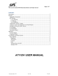
1
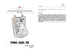
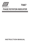
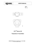
Limited Warranty
Products manufactured by Walrus Pumps Co (Walrus) are warranted to the first user only
to be free of defects in material and workmanship for a period of 12 months from date of
installation, but no more than 24 months from date of shipment. Walrus' liability under this
warranty shall be limited to repairing or replacing at our election, without charge, FOB
Walrus' distribution center or authorized service agent. Walrus will not be liable for any
cost of removal, installation, transportation or any other charges that may arise in
connection with warranty claim.
Inverter Control Pump
Instruction Manual
The warranty period commences on the date of original purchase of the equipment. Proof
of purchase and installation date, failure date, and supporting installation data must be
provided when claiming repairs under warranty.
This warranty is subject to due compliance by the original purchaser with all directions and
conditions set out in the installation and operating instructions. Failure to comply with
these instructions, damage or breakdown caused by fair wear and tear, negligence, misuse,
incorrect installation, inappropriate chemicals or additives in the water, inadequate
protection against freezing, rain or other adverse weather conditions, corrosive or abrasive
water, lightning or high voltage spikes or through unauthorized persons attempting repairs
are not covered under warranty.
Walrus will not be liable for any incidental or consequential damages, losses, or expenses,
arising from installation, use, or any other causes. There are no express or implied
warranties, including merchantability or fitness for a particular purpose, which extend
beyond those warranties described or referred to above.
Certain states do not permit the exclusion or limitation of incidental or consequential
damages or the placing of limitations on the duration of an implied warranty, therefore, the
limitations or exclusions herein may not apply. This warranty sets forth specific legal rights
and obligations, however, additional rights may exist, which may vary from state to state.
WALRUS PUMP CO., LTD.
Web: www.walruspump.com
CC70D0008D000EW0R01
Supersedes all previous publications
ISO 9001 Certified
Walrus Pump Co., Ltd.
1. Preface:
f.
We appreciate your purchase of this
Inverter Control Pump of variable
frequency and constant pressure. For
correct installation and use of this product,
be sure to read this user's manual before
proceeding with the installation for the
sake of sound performance and safety.
Please keep this manual all the time for
future reference in maintenance, service
and repairs.
When you purchase the product, be sure
that it has undergone strict test and has
been duly packed and handled with
consideration of all factors. Before
installation, be aware of the following and
all irregularities shall be notified to the
dealer of this office for solutions.
a. Damage of deformation during
transportation.
b. Complete parts when you unpack the
product.
c. Do the specifications of the product
match the nameplate (Pressure and HP)?
d. Normal keys on the keyboard.
e. ISO label.
2. Functions and features:
a.
Variable frequency and constant
pressure control this product. Once the
constant pressure is set, its service
pressure will never exceed the preset
one. (This is not the case for pressure
difference type).
b. Smooth start and stop, low noise,
minimum vibration and no water
hammer.
c. No-water auto break as protection of the
motor with auto start until water supply
is resumed.
d. Auto water leakage sensor with pressure
compensation.
e. In case of irregular variable frequency
and constant pressure, the product is
switched as a pressure difference type
product, thus assuring water supply all
the time. (TPH2T/4T-IC Standard model
without pressure difference function.)
Compact, easy installation and
operation.
g. Power supply of single phases 220V,
3-phase 220V and 3-phase 380V.
7.4 TPH2T/4TIC Standard model Single-phase 220V variator
Control box
3. Installation and remarks
3.1 Site of installation
As the environment of the site of
installation mainly determines service life
of the product, the follow sites are
recommended for installation:
a. Ambient temperature +4oC~+40oC with
good ventilation and dryness.
b. Try not to install it outdoors to avoid
sunshine and rain.
c. Installation sites free of vibration and
major surges.
d. Installation sites for easy maintenance
and service.
3.2 Installation remarks
a. To install the pump, keep out impurities.
It's important to keep plastic pipes free
of PVC glue, metal dregs that may jam
the wheels.
b. Add NFB to input power supply as
protection to the variator and the motor.
c. Is symbol for grounding terminal. Be
sure to ground it for electric shocks.
d. Be sure of the power supply of single
phase 220V, 3-phase 220V and 3-phase
380V.
e. Never run the product without water and
keep water temperature at below 40oC
and do not user other liquids than water.
f. A metallic pipe should be used as the
outlet pipe to avoid breakage due to high
pressure or abnormal liquid temperature.
4.Console
3-phase 1-phase
power
power
Variator
NFB
NFB
SFSWCOM + IN
1 2
In case of 3-phase 220V
Connect any 2 wires
L1L2
FAN
T.S.
Motor
Red
White
Pressure
sensor
7.5 Remarks
a. To avoid frequent off of the thermostat in areas of hot water, remove the thermostat
switch and have SF be connected with COM and keep water temperature at below 60oC.
b. To add a water level switch, connect the water level switch with the thermostat switch.
4.1 ● RUN
The constant pressure indicator that goes
on during operation at constant pressure.
4.2 ● PSW
The pressure difference indicator that goes
on during operation with pressure
difference.
~1~
WVU
L1L2
~6~
4.3
7.2 3-phase variator
4.11
SET
PSW
Control box
3-phase
power
Variator
Digital display of pressure setting
(Maximum pressure set per model and
pressures required.)
NFB
4.4
T.S.
o 380V
FAN
o 220V
SFSWCOM + IN
ACTUAL
1 2
L1L2L3 3
4
WVU
L1 L2L3
Digital display of actual pressure
4.5
Motor
Red
Pressure
switch
White
2-digit display of pressure up between
00~99.
Pressure
sensor
4.6
7.3 3-phase 5HP variator
Control box
2-digit display
between 00~99.
of
pressure
down
4.7
3-phase
power
PROG
Variator
Function memory key for all functions and
data.
T.S.
o 380V
FAN
o 220V
NFB
4.8
SFSWCOM + IN
STOP
1 2
L1L2L3 3
4
WVU
The key to stop the pump.
L1 L2L3
4.9
RUN
The key to start the pump.
Motor
Red
Pressure
switch
~5~
White
Pressure
sensor
4.10
AUTO
Auto key to run the pump on constant
pressure when ● RUN goes on
The key to run the pump with pressure
difference when ● RUN and ● PSW go on
at the same time.
5. Operation
5.1 Power on
5.1.1 Check the variator and the wiring
diagram. The single phase variator
runs on 220V ±10% (In case of 3-phase
220V ±10%, just connect any 2 of the
wires). A 3-phase variator runs at
3-phase 220V ±10% or 380V ±10%.
5.1.2 Remove the water stop and fill the
pump compartment before tightening
the water stop.
5.1.3 Try to check if the wind hood runs in
the same direction that of the steering
nameplate.
5.2 When using auto control:
5.2.1 Press AUTO and then press PROG to
switch the computer to run on
VARIABLE AUTO.
5.2.2 Press and
for a desired pressure
and then press PROG to complete the
setting.
5.2.3 To change the pressure setting, just
repeat 5.2.2.
5.3 Pressure switch
5.3.1 Press PSW, at this time ● PSW of the
upper left goes on. Press PROG to
have the computer switch to
PRESSURE SWITCH for pressure
setting.
5.3.2 To resume AUTO, press AUTO and
● PSW of the upper left goes off.
Press PROG to resume AUTO.
5.4 Remarks
5.4.1 Failure to press PROG after pressing
SET or adjusting pressure figures, the
function that had been set earlier will
be resumed in case of blackout.
5.4.2 After the power goes off when there is
no water, the display will show OL.
Wait 10 minutes before the motor
~2~
restarts on its own. To force the pump
to run, press STOP and then RUN to
resume the operation.
5.4.3 PSW does not work when the pump
runs on AUTO.
AUTO does not work when the pump
runs on PSW.
5.4.4 It is recommendable to use AUTO for
regular operations, as PSW is
available as replacement.
6. Troubleshooting:
6.1 Pump motor
(Before proceeding with this step, turn the
power off.)
6.1.1 The motor does not run:
a. Check for correct voltage.
b. Check for water supply.
c. Check for stuck pump.
d. When working on PSW, be sure to
check if the silver contact of the
pressure switch is on, if not, the
silver contact may go oxidized and
cleaning would become necessary.
e. When the water temperature goes
high, the thermostat switch would go
off. Once the water is cooled, the
operation would be resumed
automatically.
f. If the operation fails to go on, call
service.
6.1.2 When the motor keeps running when
with the water supply cut:
a. Check if the faucet is tightened and
whether the toilet and piping is
leaking.
b. Open the check valve to check for
sticking or leakage.
c. Low power supply.
6.2 Variator:
6.2.1 SF display: No operation. The safety
terminal is OFF.
a. Check the wiring protection for
interruption.
b. If no SF terminal is in use, be sure to
have the SF terminal be connected
with COM terminal.
6.2.2 OPE1 display: Warning on erroneous
setting.
a. Reset to run the operation once
more after power off.
b. If the same message appears again,
call for service.
6.2.3 OL display: Abnormal display with
water and power off.
a. Check for cut power supply.
b. Check if the pressure sensor has
signals.
c. Check the pump.
d. In OL try starting the pump until
water is available every 10 minutes.
e. To force the pump to run, press
STOP and then RUN to resume the
operation.
6.2.4 EEP 1/EEP 2 display: Irregular
memory.
a. Reset and then press PROG.
b. If the same problem appears, call for
service.
6.2.5 PF01/PF02/PF03/PF04 display for
irregular drive:
a. Reset to run the operation once
more after power off.
b. If the same message appears again,
call for service.
6.3 Remarks:
a. For safe service, be sure to turn off
the pump.
b. When the red warning light in the
variator goes on, be sure to keep
your hands off the parts and the
circuit board for electric shock.
c. In case of failure of the internal
parts, do not try to replace or repair
them yourself, or this office would
not
be
responsible
for
consequences.
~3~
7. Wiring diagram
7.1 Single-phase 220V variator
Control box
3-phase 1-phase
power
power
Variator
NFB
NFB
SFSWCOM + IN
In case of 3-phase 220V
Connect any 2 wires
L1L2
3 4
1 2
WVU
L1L2
FAN
T.S.
Motor
Red
Pressure
switch
~4~
White
Pressure
sensor