1
NOTE:
IT IS ABSOLUTELY IMPERATIVE THAT A GOOD GROUNDING
SYSTEM BE INSTALLED.
Grounding circuits for Irrigation Systems consist of ground rods, ground plates, copper
strips, straps and solid copper wire. With electro-mechanical equipment, ground rods
provide adequate safety and protection. Ground plates, both alone or in conjunction with
ground rods, should be used to protect electronic equipment, because ground plates
exhibit low inductance/impedance characteristics and therefore are better suited for
protection of electronic equipment. The ground system will consist of one or more
properly installed ground rods, or plates, connected through appropriately sized wire to
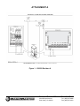
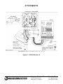
the controller. This is described in detail in each Controller’s User Manual.
The safety (green wire) ground from the electrical service is NOT suitable for a lightning
ground. The small wire size, long length, and questionable connections make it
unsuitable for protection against transients. The only acceptable grounding method for
lightning protection is a properly installed and connected ground rod/plate system.
3.0
IMPLEMENTATION
A single 8 foot copper clad ground rod, properly installed, is usually sufficient. The rod
must extend beyond the frost line if possible. The rod should be driven in, not installed in
an augured hole. You may core through a concrete pad or foundation. It should be
located as close as possible to the controller, so that the AWG #6 ground wire is as short
and direct as possible, free of nicks and bends. The ground clamp inside the controller
should be used as the ground point. Be sure to remove any oxide from the copper clad
rod before attaching the ground clamp to the rod. Be sure all connections are solid and
secure.
Should the 8 foot grounding rod not penetrate completely into the soil it is acceptable to
put it into the ground on a slight angle of not more than 45° relative to the vertical
position. It is important that the rod be a full 8 feet into the ground, with only enough of
the rod showing to clamp the wire on.
Circuit impedance is critical to the effectiveness of the ground circuit and cannot be
measured in the field in a practical way. Proper installation is more important to assure
quality results than this measurement. Make sure to meet the minimum requirements of
the NEC (National Electric Code), which are;
a)
b)
A resistance reading of no more than 25 ohms.
A two electrode ground grid.
For installations that require multiple equipment locations, the resistance measurements
of the ground circuits should be compared for consistent readings. Large discrepancies
in the readings allude to different soil conditions, soils with different moisture content, or
improper installation.
Technical Bulletin 025
Sheet 2 of 7
3910-B Royal Avenue
Simi Valley, CA 93063
Tel: (805) 527-4498
Fax: (805) 527-2813