1
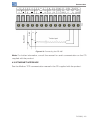
I/O Status
Internal analog input and output
By pressing the back key, we go to the next status screen, which shows the internal analog
input and output:
AI1: 9.1V 18.2mA
AO1:10.0V 20.0mA
The example screen above shows the voltage at the analog input AI1, of 9.1 V, or, if you
are measuring current, 18.2 mA.
In the option 4 to 20 mA, the value that the ladder sees is a proportional, standardized
value, that is, 4 to 20 mA → 0 to 32767, but the status shows the real value of the current.
The analog output AO1, is with 10 V or 20 mA, simultaneously, depending on the physical
output that is being used (see XC2).
Digital output DO9 in PWM
If the digital output DO9 is programmed as PWM, by pressing the back key, we can see
the screen that shows this output data:
FREQ.: 10.12kHz
DUTY : 84.90%
Expansions
If there are expansions, we access the screens that show their status by pressing the
back key. The expansion screens depend on the type of I/O that each expansion contains.
For instance, an IOA-01, which has 1 analog input, 2 analog outputs, 2 digital inputs and
2 digital outputs:
I108-01:00000011
O108-01:00000010
Note that, due to the lack of space, the numbers are abbreviated. ‘I108-01’ means the
digital inputs of the slot 1, ranging from 108 to 101. Likewise, ‘O108-01’ indicates the digital
outputs of the slot 1, ranging from 108 to 101.
The example screen shows the digital inputs and outputs of the expansion IOA-01, in
the slot 1, where the inputs DI101 and DI102, as well as the output DO102, are active, by
pressing the rear key again, we can see the analog inputs and outputs of this expansion,
one per screen:
AI101: -10.0V
20.0mA
AO101: -10.0V
20.0mA
AO102:
8-4 | PLC300
9.0V
18.0mA