1
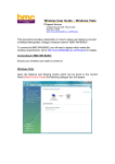
INSTALLATION AND SETUP OF ASL
EYE TRACKING SYSTEM
MODEL 504 WITH PAN/TILT OPTICS
Francesc Tintó Garcia-Moreno
March – August 2001
Copyright 2001, Queen’s University of Belfast
INSTALLATION AND SETUP OF ASL EYE TRACKING SYSTEM
1
Summary
1
Components:...........................................................................................................2
3
Connections: ...........................................................................................................4
3.1
Model 5000 Control Unit.................................................................................................................4
3.2
Pan Tilt Eye Camera Optics Module ...............................................................................................7
3.3
Floor Mounted Scene Camera (FMSC) ...........................................................................................9
3.4
Scan Converter ..............................................................................................................................10
3.5
Eye Tracker Interface PC...............................................................................................................12
3.6
Monitors ........................................................................................................................................13
3.7
Video Cassette Recorder (VCR)....................................................................................................15
3.8
Matrox Marvel G400-TV ..............................................................................................................18
4
Using the Eye Tracking System: .............................................................................21
4.1
Upload Software to the Control Unit.............................................................................................21
4.2
E5000 User Interface Program ......................................................................................................22
4.2.1
Setting Up Calibration Target Points.....................................................................................22
4.2.2
Subject Setup and Calibration................................................................................................24
4.2.2.1 Subject Seating: .................................................................................................................24
4.2.2.2 Obtaining an Eye Image: ...................................................................................................24
4.2.2.3 Pupil and CR Discrimination.............................................................................................25
4.2.2.4 Subject Calibration ............................................................................................................26
4.2.3
Data Recording ......................................................................................................................27
2
Placing all the devices:.............................................................................................3
Francesc Tintó Garcia-Moreno
School of Computer Science, Queen’s University of Belfast
INSTALLATION AND SETUP OF ASL EYE TRACKING SYSTEM
2
1 Components:
1. ASL Eye tracking system Model 504 with Pan/Tilt optics including:
•
Model 5000 control unit and plug in power supply
•
Pan/tilt optics eye camera optics module
•
Scene camera with tripod, or scan converter
•
Two video monitors (one for the eye image and one for the
scene image)
•
Cables for connecting the model 5000 control unit to the
Interface PC, to the pan/tilt optics and scene camera, and to the
two monitors
•
Control and analysis software
2. Two PCs, an interface PC and a Display PC
3. Matrox Marvel G400-TV video card
4. Panasonic Video Cassette Recorder AG-4700
5. Cables for connecting the model 5000 control unit to the Video
Cassette Recorder, and VCR to Matrox Marvel G400-TV
Francesc Tintó Garcia-Moreno
School of Computer Science, Queen’s University of Belfast
INSTALLATION AND SETUP OF ASL EYE TRACKING SYSTEM
3
2 Placing all the devices:
Before unpacking the ASL Eye Tracking System it is recommended to
think about how to place it for having best results. The most important
thing to consider is where to place the subject whose eye gaze we want
to track. There must be no windows or intense sources of light in front of
the subject. In addition, the ambient light must be as stable as possible.
There is another point of consideration: the Interface PC and the two
Video Monitors can be a distraction for the subject of the experiment. It
is recommended to keep them out of the subject’s view. The
recommended placement is shown in Figure 1. The computers are placed
forming an “L”, while the subject looks at the Display PC or at a TV
Screen, and the Interface PC and the Video Monitors are placed behind
the subject. This allows the person in control of the Eye Tracking System
to control the Interface PC, the Video Monitors but also the subject and
the Pan Tilt Optics. In addition, if the system is placed in that way the
subject cannot be distracted.
Figure 1: Placement of the Eye Tracking System
Francesc Tintó Garcia-Moreno
School of Computer Science, Queen’s University of Belfast
INSTALLATION AND SETUP OF ASL EYE TRACKING SYSTEM
4
3 Connections:
The ASL Eye Tracking System Model 504 is supplied with a user manual
that explains how to make the connections between all the devices
coming with it. All the connectors are labeled and both connectors and
cables, are colour coded in order to facilitate the assembly. The following
section gives a short review of how to make the assembly of the Eye
Tracking System. We show how to connect it to the Video Cassette
Recorder in order to record on tapes (analog storage) the output video
signal coming from it. Finally shows how to connect it to the Matrox
Marvel G400-TV graphic card in order to record the output video signal
into streaming video files (digital storage). For further information please
refer to the device manufacturer manuals.
3.1 Model 5000 Control Unit
The control unit houses the processing board that receives video from
eye and scene cameras, recognizes features in the video eye image and
computes line of gaze, communicates with the Interface PC, controls the
pan/tilt mechanism, and superimposes feedback outlines, cross hairs,
and cursors on the eye and scene video signals for monitor display.
When an optional magnetic head tracker is used, this processing board
also communicates with the head tracker and can use the head position
data to assist with control of the pan/tilt mechanism.
Basic use of the device requires the connectors labeled “Controller”,
“Camera”, “Remote Scene”, “Eye Out”, “Scene Out”, and “12V DC IN”. Other
connectors support various options or secondary functions such as
communications with a head tracker and data output to an external
device.
Francesc Tintó Garcia-Moreno
School of Computer Science, Queen’s University of Belfast
INSTALLATION AND SETUP OF ASL EYE TRACKING SYSTEM
[2]
[3]
[6]
[5]
[4]
[1]
[7]
5
[8]
[9]
[10]
[11]
Figure 2: Back panel of Control Unit
a) Locate the 12VDC power supply module and connect it to the “DC
Power” connector on the Control Unit (marked [1] in Figure 2).
Connect the other side to an AC power outlet. The power supply is
input rated for 100 - 240 VDC, 50 or 60 Hz. The LED on the Control
Unit front panel should remain off until the power switch is switched
on.
b) For use with Pan Tilt Optics, be sure that the slide switch on the rear
panel (marked [2] in Figure 2) is in the “P/T” position.
c) NOT STANDARD USE. The connector labeled “Analog I/O” provides
two channels of analog output (marked [3] in Figure 2). One analog
channel outputs a voltage corresponding to the horizontal eye
position coordinate, and the other outputs a voltage corresponding to
the vertical eye position coordinate. The voltages are proportional to
the horizontal and vertical positions of the point of gaze cursor on
the scene monitor and the digital gaze coordinates. It is a male, 9 pin,
D type connector.
d) NOT STANDARD USE. The connector labeled “Serial Out” is an RS232
port that allows the output of the eye tracker data (marked [4] in
Figure 2). It is a male, 9 pin, D type connector.
e) The connector labeled “Remote Scene”, coded in white, can receive the
signal coming from the Scene Camera or the Scan Converter (marked
Francesc Tintó Garcia-Moreno
School of Computer Science, Queen’s University of Belfast
INSTALLATION AND SETUP OF ASL EYE TRACKING SYSTEM
6
[5] in Figure 2). It is a female, 9 pin, D type connector. The incoming
video signal must be in PAL composite standard and can be inputted
using a cable with a phono plug or a BNC plug. An adaptor is
provided to make it possible.
f) NOT STANDARD USE. The connector labeled “X Dat” provides access
to a parallel digital port that is used as a means of inputting external
data (marked [6] in Figure 2). Sixteen bits of parallel, TTL level,
positive true data, from any source, can be recorded by the E5000
control program, along with the other eye tracker data. It is a female,
25 pin, D type connector.
g) The connector labeled “Controller”, coded in green, allows the data
transfer between the Control Unit and the Interface PC (marked [7] in
Figure 2). It is a male, 9 pin, D type connector. The interface cable is
provided and it is also colour coded green. It is connected to the
Interface PC by its serial port.
h) NOT STANDARD USE. The connector labeled “Head Tracker” is an
RS232 port that allows communication between the Control Unit and
the optional Magnetic Head Tracking (MHT)1 control unit (marked [8]
in Figure 2). It is a male, 9 pin, D type connector.
i) The connector labeled “Eye Out”, coded in orange, provides the image
of the eye coming from the Pan Tilt Optics (marked [9] in Figure 2). It
is a BNC connector. The Control Unit outputs a PAL composite video
signal that can be displayed in one of the Video Monitors. The
interface cable is provided and it is also colour coded orange.
j) The connector labeled “Scene Out”, coded in blue, provides the image
of the scene coming from the Scene Camera or the Scan Converter
where the Control Unit has added a cross hair pointing to the centre
of eye gaze (marked [10] in Figure 2). It is a BNC connector. The
Control Unit outputs a PAL composite video signal that can be
displayed in one of the Video Monitors. The interface cable is
provided and it is also colour coded blue.
1
The magnetic head tracking option (MHT) is a small unit that determines head position and orientation
with good accuracy in six degrees of freedom. The head tracker can be used by the Control Unit to assist in
determining positions for the pan/tilt mechanism.
Francesc Tintó Garcia-Moreno
School of Computer Science, Queen’s University of Belfast
INSTALLATION AND SETUP OF ASL EYE TRACKING SYSTEM
7
k) The connector labeled “Camera”, coded in red-white, receives the
signal coming from the Pan Tilt Optics (marked [11] in Figure 2). It is
a male, 25 pin, D type connector. The interface cable is provided and
it is also colour coded red-white.
3.2 Pan Tilt Eye Camera Optics Module
The Pan/Tilt module is shown in Figure 3. The eye camera is mounted on
a moving platform. A ring of near infrared LEDs around the lens opening
provides eye illumination.
In order to get optimal conditions the Pan/Tilt module must be placed
just in front of the stimulus monitor and centred horizontally.
Figure 3: Pan/Tilt module
A main power switch, and all the necessary connectors are located on the
base (non-moving) platform rear panel, accept for the illuminator power
connector (marked [1] in Figure 4) which is located at the rear of the
moving platform. The Control Unit powers the illuminator. A suitable plug
comes with the cable provided.
Francesc Tintó Garcia-Moreno
School of Computer Science, Queen’s University of Belfast
INSTALLATION AND SETUP OF ASL EYE TRACKING SYSTEM
8
A separate power supply connects to a DC power input connector, labeled
“DC in 13.5V” (marked [2] in Figure 4), on the rear panel and plugs into a
standard AC wall outlet.
Two of the real panel connectors are used for the Eye Tracking System.
They are colour coded to make easier the assembly.
a) The connector labeled “Video OUT”, coded in yellow, outputs a PAL
composite video signal (marked [3] in Figure 4). It is a phono socket.
b) The connector labeled “VISCA in”, coded in yellow-blue, allows the
Control Unit to control the Pan/Tilt Optics Module (marked [4] in
Figure 4). It is an 8 pin mini-DIN socket.
The appropriate lead to connect with the “Camera” connector of the
Control Unit is provided and colour coded.
[1]
[3]
[4]
[2]
Figure 4: Pan/Tilt rear panel
An IR remote control unit provides manual control for Pan/Tilt
positioning, lens focus and zoom, and various other features built into
the pan/tilt camera. It is shown in Figure 5.
Francesc Tintó Garcia-Moreno
School of Computer Science, Queen’s University of Belfast
INSTALLATION AND SETUP OF ASL EYE TRACKING SYSTEM
9
Figure 5: Pan/Tilt remote control
3.3 Floor Mounted Scene Camera (FMSC)
The scene camera is used to produce a video image of the same scene
the subject views. This video scene image provides the reference frame
for the eye point of gaze measurement. The colour scene camera,
provided by ASL as part of the standard model 504 system, is powered
directly from the Control Unit, is equipped with an 8 mm lens, and
includes a standard photography tripod to support the camera.
[2]
[1]
Figure 6: Scene Camera
Francesc Tintó Garcia-Moreno
School of Computer Science, Queen’s University of Belfast
INSTALLATION AND SETUP OF ASL EYE TRACKING SYSTEM
10
The Scene Camera has two connectors:
a) The power input connector (marked [1] in Figure 6).
b) The PAL composite video output connector (marked [2] in Figure 6). It
is a phono socket and it is colour coded in white.
The appropriate lead to connect with the “Remote Scene” connector of the
Control Unit is provided and colour coded.
3.4 Scan Converter
Alternately, if eye tracking subjects will be looking at a computer screen,
the system may include a Scan Converter in place of the Scene Camera.
The scan converter converts the VGA computer screen image (being
viewed by the subject) to a PAL composite video signal that can be input
to the eye tracker Control Unit as the scene video image.
The Scan Converter used is a Vine Micros Ltd. CORIOscan Connect. All the
connectors are located on the rear panel.
[1]
[2]
[3]
[4]
[5]
[6]
Figure 7: Scan Converter
Francesc Tintó Garcia-Moreno
School of Computer Science, Queen’s University of Belfast
INSTALLATION AND SETUP OF ASL EYE TRACKING SYSTEM
11
a) The DC power input connector is labeled “Power” (marked [1] in
Figure 7). The appropriate power supply is provided within the Scan
Converter package.
b) The connector labeled “PC In” is a VGA input socket (marked [2] in
Figure 7). It is the only video signal input socket available in this
model. Connect this socket to the monitor output socket on the
Display PC using the computer lead supplied.
c) The connector labeled “PC Out” is a VGA output socket (marked [3] in
Figure 7). Internally the video signals are looped-through, allowing
use even when the unit’s power is off. Connect the computer
monitor’s video lead to this socket.
d) The connector labeled “Composite Video Out” is a PAL composite
video output (marked [4] in Figure 7). The appropriate phono to
phono plug lead is supplied. This is the output that is used to connect
with the “Remote Scene” connector of the Control Unit.
e) NOT STANDARD USE. The connector labeled “S-Video Out” is an SVideo output (marked [5] in Figure 7). An S-Video lead is supplied.
f) NOT STANDARD USE. The connector labeled “RGB Out” is an RGB
output (marked [6] in Figure 7). The appropriate lead is supplied, its
plugs are 15 pin male D type to SCART.
An IR remote control unit is provided allowing the user to change the
Scan Converter settings. It is shown in Figure 8.
Figure 8: Scan Converter remote control
Francesc Tintó Garcia-Moreno
School of Computer Science, Queen’s University of Belfast
INSTALLATION AND SETUP OF ASL EYE TRACKING SYSTEM
12
If a TV Screen is used instead of the Display PC the scan converter is not
necessary. The composite output of the TV Set can be directly inputted
into the “Remote Scene” connector of the Control Unit using a phono to
phono plug lead.
3.5 Eye Tracker Interface PC
This computer serves as the user interface device and as a data-recording
device.
a) Use the provided cable to connect the port labeled “Controller” on the
Control Unit to the COM1 port on the Interface PC as shown in Figure
9. Both plugs of the lead are colour coded in green.
Figure 9: Serial port of the Interface PC
b) ASL always supplies an Eye Tracker Interface program, which runs on
this computer, and it is a required part of the system2. Eye Tracker
software is shipped on a CD. Follow the directions on the label to
2
System requirements for the Interface PC are an IBM compatible PC capable of operation with Windows
95, Windows 98, Windows ME, Windows NT, Windows 2000, or DOS. However, a computer that can run
only DOS is limited to using only the DOS version of ASL’s Eye Tracker Interface Program. The computer
must also have available COM1 or COM2 serial ports using standard interrupts and device addresses. The
minimum recommended system is a 200 MHz Pentium, but slower systems will probably work adequately
as well.
Francesc Tintó Garcia-Moreno
School of Computer Science, Queen’s University of Belfast
INSTALLATION AND SETUP OF ASL EYE TRACKING SYSTEM
13
install the EYEPOS eye tracker operating software, EYENAL offline data
analysis software, and ACCESS C language subroutines for reading
binary data files recorded by the EYEPOS software. The CD will also
copy to the hard disk the install files for FixPlot, the fixation scan path
plotting program. As a default, the CD will create a directory named
“ASL
software”
with
subdirectories
named
“EYEPOS”,
“EYENAL”,
“ACCESS”, and “FIXPLOT”, containing the corresponding software files.
To actually install FixPlot, run setup.exe in the FIXPLOT directory.
3.6 Monitors
Two 9” black and white monitors, AD 910A model, are supplied by ASL to
display the image of the eye coming from the Pan Tilt Optics and the
image of the scene coming from the Scene Camera or the Scan Converter
where the Control Unit has added a cross hair pointing to the centre of
eye gaze.
Francesc Tintó Garcia-Moreno
School of Computer Science, Queen’s University of Belfast
INSTALLATION AND SETUP OF ASL EYE TRACKING SYSTEM
14
[1]
[3]
[2]
Figure 10: Back of the Eye and Scene Monitors
c) Connect a video cable from the eye monitor video input (marked [1] in
Figure 10), to the Control Unit connector labeled "Eye Out”. A BNC to
BNC lead is provided, both plugs are colour coded in orange.
d) Connect a video cable from the scene monitor video input (marked [2]
in Figure 10), to the Control Unit connector labeled "Scene Out”. A BNC
to BNC lead is provided, both plugs are colour coded in blue.
The inputted video signals are looped-through to a BNC output on the
back of the monitors (marked [3] in Figure 10). This output can be used
Francesc Tintó Garcia-Moreno
School of Computer Science, Queen’s University of Belfast
INSTALLATION AND SETUP OF ASL EYE TRACKING SYSTEM
15
to connect with the Video Cassette Recorder or the Matrox Marvel G400-
TV using a BNC to phono plug lead.
3.7 Video Cassette Recorder (VCR)
The only requisite for choosing a VCR is that it must have a composite
line input. The model used is a Panasonic Super VHS VCR AG-4700.
Signal can be recorded from different sources and outputted to other
devices.
•
Getting the scene video image from the Eye Tracking System:
a) Use a BNC to phono plug lead to connect the output of the Scene
Monitor ( as explained in point 6 ) to the composite video input of
the VCR. The socket is labeled “AV3 VIDEO IN” and is placed on the
front of the VCR (marked [1] in Figure 11).
[2]
[1]
Figure 11: VCR video input AV3 detail
b) Ensure that the switch labeled “INPUT SELECT” on the front of the
VCR is set to “LINE” as shown in Figure 12.
Francesc Tintó Garcia-Moreno
School of Computer Science, Queen’s University of Belfast
INSTALLATION AND SETUP OF ASL EYE TRACKING SYSTEM
16
Figure 12: INPUT SELECT switch detail
c) Choose the right input channel using the (+) and (-) buttons placed
on the control panel on the front of the VCR ( see Figure 13). “A3”
must appear on the display of the VCR as shown in Figure 14.
Figure 13: VCR control panel detail
Francesc Tintó Garcia-Moreno
School of Computer Science, Queen’s University of Belfast
INSTALLATION AND SETUP OF ASL EYE TRACKING SYSTEM
17
Figure 14: VCR display detail
•
Getting the scene video image from the Matrox Marvel G400-TV:
There are two ways of connecting the VCR with the Matrox Marvel G400-
TV. Either S-Video or Composite video signal can be used. Using S-Video
provides best quality.
a) Use a phono to phono plug lead for composite video signal or SVideo lead otherwise. Connect the appropriate cable to the video
input of the VCR. The socket is labeled “AV3 VIDEO IN” if you want
to use composite video and “AV3 S-VIDEO IN” if you are using SVideo (marked [2] in Figure 11).
b) Set the “INPUT SELECT” switch to “LINE” for composite video or “SVIDEO” for S-Video.
c) Choose the right input channel using the (+) and (-) buttons placed
on the control panel on the front of the VCR. “A3” must appear on
the display of the VCR.
Outputting the scene video image to Matrox Marvel G400-TV:
a) Use a phono to phono plug lead for composite video signal or S-Video
lead otherwise. The output sockets are on the back of the VCR and
they are labeled “VIDEO OUT” (marked [1] in Figure 15) for composite
video and “S-VIDEO OUT” (marked [2] in Figure 15) for S-Video.
Francesc Tintó Garcia-Moreno
School of Computer Science, Queen’s University of Belfast
INSTALLATION AND SETUP OF ASL EYE TRACKING SYSTEM
18
[1]
[2]
Figure 15: VCR video output detail
b) Ensure that the input channel is set to “A3”.
3.8 Matrox Marvel G400-TV
The Matrox Marvel G400-TV is all-in-one graphics, video capture and
video editing card. The external box makes it easier to connect other
video devices without having to grasp and reach behind your computer.
The Matrox Marvel G400-TV is provided with software that allows the
storage of inputted signal in streaming video (digital format).
There are two input and output sockets offering the possibility to use
either Composite video or S-Video formats. The input sockets are on the
front of the external box as shown in Figure 16. The composite video
socket is marked [1] and the S-Video socket is marked [2].
Francesc Tintó Garcia-Moreno
School of Computer Science, Queen’s University of Belfast
INSTALLATION AND SETUP OF ASL EYE TRACKING SYSTEM
[1]
19
[2]
Figure 16: Input sockets of Marvel G400-TV detail
For inputting the signal coming from the “Scene out” of the Control Unit
you must use the Composite video input.
When the signal comes from the VCR either Composite video or S-Video
can be used.
The output sockets are on the back of the external box as shown in
Figure 17. The composite video socket is marked [1] and the S-Video
socket is marked [2].
[2]
[1]
Figure 17: Output sockets of Marvel G400-TV detail
Francesc Tintó Garcia-Moreno
School of Computer Science, Queen’s University of Belfast
INSTALLATION AND SETUP OF ASL EYE TRACKING SYSTEM
20
When the Eye Gaze Tracking system is connected to the input socket it is
possible to output its signal into the VCR. Either Composite video or SVideo can be used.
Francesc Tintó Garcia-Moreno
School of Computer Science, Queen’s University of Belfast
INSTALLATION AND SETUP OF ASL EYE TRACKING SYSTEM
21
4 Using the Eye Tracking System:
The EYEPOS (E5000) software package contains software that must be
uploaded to the model Control Unit as well as a user interface program
that runs on the Interface PC.
Make sure that all the devices of the system are switched on before
uploading the software to the Control Unit and launching the interface
program.
4.1 Upload Software to the Control Unit
Use the power switch to power cycle the Control Unit off and back on
again to be sure that it is “reset”. Switch on the power switch at the rear
of the pan/tilt module.
Upload software to the model 5000 eye tracker control unit by running
Load.bat3. The upload program will begin to execute in a “command line”
box. The PC monitor will display
UPLOAD Vn.n - Program/Pattern upload program for ASL ETE
Loading: path/E5nnn.BXT (nnnnn bytes)
bytes left: nnnnn
The “bytes left” number will count down to zero and then the PC monitor
will display
Done
Loading: path/E5nnn.LXR (nnnnn bytes)
bytes left: nnnnn
The “bytes left:” value will count down to zero and the monitor will
display.
3
The ASL Manual notes that Load_nt.bat must be executed instead of Load.bat when using Windows NT
operating system. During the tests we have noticed that Load_nt.bat does not work properly and Load.bat
must be used anyway. Using Load.bat the system will still work properly.
Francesc Tintó Garcia-Moreno
School of Computer Science, Queen’s University of Belfast
INSTALLATION AND SETUP OF ASL EYE TRACKING SYSTEM
22
Done
This operation must last a minute and a half approximately. If the upload
is not successful the “command line” box will be closed before the end or
an error message will appear on it. If this is the case, try to run the batch
file again so that the upload succeeds. Sometimes it is useful to switch
the Control Unit off and on again in order to reset it. Once the control
unit has been “loaded” the on board software will continue to run until
power is turned off.
4.2 E5000 User Interface Program
The user interface PC software is needed to change settings such as pupil
and corneal reflection discrimination thresholds, launch procedures such
as calibration, and to record data on the Interface PC. All eye tracking
functions are performed by the Control Unit. Once proper settings are
established, and if data is not being recorded on the Interface PC, the eye
tracker will continue to function normally even if the cable to the
interface PC is disconnected.
Run the interface program e5win.exe which is located in the C:\ASL
Software\EYEPOS V5.10\ folder. If the Interface PC is correctly connected
to the Control Unit and software has successfully been uploaded to the
Control Unit the “Online” light, near the top left of the interface program
screen, should be green.
4.2.1 Setting Up Calibration Target Points
During the calibration procedure it will be necessary for the subject to
look at nine target points that are at known positions. The actual
distribution of the nine points is usually taken from the scene monitor,
and entered into memory with the eye tracker “set target points” function.
The target pattern used is a Powerpoint slide displayed on the stimulus
monitor (Display PC or TV Screen4).
4
If this is the case, the slide can be recorded on a video tape for several minutes using Matrox Marvel
G400-TV video card.
Francesc Tintó Garcia-Moreno
School of Computer Science, Queen’s University of Belfast
INSTALLATION AND SETUP OF ASL EYE TRACKING SYSTEM
23
Optimally, the middle vertical and horizontal points should be co-linear
and perpendicular. All points must be numbered from left to right; 1-3
for the top row, 4-6 for the middle row and 7-9 for the bottom row5.
Figure 18 shows the target pattern used for calibration.
Figure 18: Target pattern used for calibration
a) Select “Set Target Points” from the Calibrate pull down menu. Be sure
to drag the “Set Target Point” window to some position where it does
not cover up any of the “Scene POG” graphics display on the main
Window.
If the Set Target Point window is present, whenever the mouse cursor
enters the “Scene POG” Display area, it changes to a cross and its
position coordinates with respect to the Scene Display are shown as
“Scene X: nnn Y: nnn” on the Set Target Points Window. When the
mouse is moved within the Scene Display the cursor on the Scene
Monitor is also displayed in the corresponding position. The Set
Target Point window indicates the target point number that will be
specified the next time the mouse is left clicked (“specify position
for:…”).
b) Move the mouse (within the “Scene POG” area on the computer screen)
to position the cursor on the Scene Monitor over point 1, and left click
to enter point 1.
c) Similarly click on points 2-9, in sequence, to enter the other points.
5
Generally, the points cover about 80 percent of the monitor screen area and are separated by 15-20
degrees visual angle horizontally, and 10-15 degrees vertically.
Francesc Tintó Garcia-Moreno
School of Computer Science, Queen’s University of Belfast
INSTALLATION AND SETUP OF ASL EYE TRACKING SYSTEM
24
d) Once all target points have been entered click “Save target points and
Check” to save the points and bring up the “Check Target Points”
window, or the “Save target points and Quit” button to save the points
and close the Set Target Points window.
4.2.2 Subject Setup and Calibration
Subject set-up consists of seating the subject in an appropriate position,
obtaining a suitable eye image on the eye monitor, and setting the pupil
and CR discriminators properly.
4.2.2.1
Subject Seating:
Any stationary chair can be used, but to the extent that the type of chair
can minimize subject motion, eye tracking accuracy will be maximized.
4.2.2.2
Obtaining an Eye Image:
a) Check the “Illuminator” check box on the program screen to turn on
the illuminators.
b) Be sure the “Pan/Tilt Tracking” radio button, near the bottom left of
the e5000 screen, is set to manual.
c) Use the Zoom buttons on the Pan/Tilt remote control to move the
Zoom until the system is able to focus on the eye of the subject.
d) Use the Cursor buttons on the Pan/Tilt remote control to aim the
pan/tilt camera at the eye.
e) Once the pan/tilt module is aimed at the eye, pull down the Pan/Tilt
menu and select “Set Home”. This will cause the program to memorize
the current position of the pan/tilt module. Subsequently selecting
“Home” from the Pan/Tilt menu will cause the module to return to this
memorized position.
Francesc Tintó Garcia-Moreno
School of Computer Science, Queen’s University of Belfast
INSTALLATION AND SETUP OF ASL EYE TRACKING SYSTEM
4.2.2.3
25
Pupil and CR Discrimination
The first stage in recognition of the pupil and CR by the eye tracker is
performed by edge detection logic. Threshold levels for pupil and CR
edge detection are adjusted with the slide switches labeled “Pupil” and
“CR”. The current discriminator levels are shown by the slide switch
positions, with the far left slide switch positions indicating that no edges
will be noticed, and positions at the right of the slides indicating even
dim edges may be detected.
A white circle designating the pupil outline, and black circle designating
the CR outline are displayed on the Eye Monitor6.
a) If it is not already checked, check the “Illuminator” check box on the
program screen to turn on the illuminators.
b) Be sure the “Pan/Tilt Tracking” radio button, near the bottom left of
the e5000 screen, is set to manual.
c) Start with pupil and CR discriminator slide switches all the way to the left.
d) Begin to increase the pupil discriminator level by moving the slide switch
to the right. White dots will begin to appear on the eye monitor. As the
discriminator is turned up further, these white dots begin to form an
outline within the pupil and when the discriminator is turned up far
enough, the dots will form a line that circumscribes the pupil. At this
point white recognition cross hairs should appear through the center of
pupil.
e) Move the discriminator to the right just far enough so that a solid
white circle forms about the pupil and white cross hairs designate the
center of pupil. Observe the eye monitor for several seconds as the
subject looks around to be sure that recognition is maintained even
when the pupil is at its smallest. If the pupil is very dim and difficult to
6
They are slightly displaced to the right of the actual pupil and CR features. Furthermore, note that the
white cross hairs which indicates the pupil center actually appear at the center of the white discrimination
circle rather than at the center of the pupil image. Similarly the black cross hairs appear at the center of the
black circle rather than the CR image. This offset is purely cosmetic and has no effect on point of gaze
computation or display. It is caused by a slight time delay between detection of an edge point and display of
the corresponding dot on the monitor, and makes the discrimination outlines easier to see. It is the true
feature edge coordinates that are being detected.
Francesc Tintó Garcia-Moreno
School of Computer Science, Queen’s University of Belfast
INSTALLATION AND SETUP OF ASL EYE TRACKING SYSTEM
26
distinguish from surrounding features, move the illumination slide
switch to the right to increase illumination intensity.
f) If the pupil discriminator is too far to the right, other areas may be
mistakenly recognized as the pupil and the recognition cross hairs may
jump to these areas. Should this happen, lower the pupil discriminator
setting by moving the slide switch left.
g) Move the CR slide switch right until a black outline forms about the CR
and black recognition cross hairs designate the center of the CR7.
h) When the pupil and CR are properly recognized for a given eye image, set
the “Pan/Tilt Tracking” radio button to “Auto” to enable automatic pan/tilt
tracking. The pan/tilt camera should be able to follow slow head motions.
Auto-focus should keep the eye image in proper focus over a range of
several inches.
4.2.2.4
Subject Calibration
The raw data measured by the Eye Tracker is the separation between the
pupil center and the corneal reflection (CR). The relation between these
raw values and eye line of gaze differs for each subject and for different
optical unit and scene camera positions. The purpose of the eye
calibration is to provide data that will allow the Eye Tracker processor to
account for individual subject differences. The objective is to have the
subject look at each of the nine calibration points. This procedure must
be performed for every subject.
a) Pop up the eye calibration window by selecting “Eye Calibration” from
the Calibrate pull down menu8.
b) Tell the subject to look at the point number as prompted on the Eye
Calibration window. Be sure that pupil and CR discrimination are
correct, and click the “Store Data for Current Point” button. The “Tell
subject to look at point number” value will automatically increment.
7
Be sure that the CR is properly recognized as the subject looks about the field of view of interest. If the
black dots form about more than one geometrically satisfactory "corneal reflection", the computer software
will select the one closest to the pupil for recognition.
8
When the Eye Calibration window is active, the interface program Scene Display and the Scene Monitor
both show the location of the next target point to be entered.
Francesc Tintó Garcia-Moreno
School of Computer Science, Queen’s University of Belfast
INSTALLATION AND SETUP OF ASL EYE TRACKING SYSTEM
27
c) When data for point 9 is entered, the Eye Calibration window will
automatically close, and calibration computations will be made and
stored.
d) To confirm accuracy of calibration, ask the subject to look at each
target point again. If one or more target points are not correct, either
repeat the entire calibration procedure or just part of it.
Figure 19 shows the discrimination panel in the interface program screen
with all controls set in a usual good working configuration.
Figure 19: Configuration controls setting
During the calibration procedure it is important to look at the eye
monitor. It is very important to be sure that stable recognition cross hairs
continue to properly indicate the pupil center and the corneal reflection
(CR). If not, make the appropriate correction to the discriminator settings.
The discriminator settings can and should be adjusted during the
calibration procedure if necessary.
The calibration procedure tends to work best when performed rapidly. If
the procedure takes too long, subjects become fatigued and have
difficulty maintaining accurate fixations on the target points.
4.2.3 Data Recording
Eye position vertical and horizontal coordinates, pupil diameter, and 16
bits of external data, called XDAT (see ASL manual), can easily be
recorded on the Interface PC hard disk. A field of data, consisting of the
Francesc Tintó Garcia-Moreno
School of Computer Science, Queen’s University of Belfast
INSTALLATION AND SETUP OF ASL EYE TRACKING SYSTEM
28
elements just listed, is recorded every 60th of a second (60 Hz update
rate).
a) Open a new data file by selecting “new” from the pull down File menu
or by clicking the new file icon on the shortcut bar. Specify a directory
and file name. If “Save as Type” is left set to “Eyedat file” a “.eyd”
extension will automatically be appended to the file name. Initially the
file name will be displayed in black letters with the message “(paused)”
after the file name.
b) To start recording data on the file click the record icon (right arrow
icon on the shortcut bar). The file name will change to red letters and
the message following the file name will change to “(recording)”. The
disk “bytes free” indicator will also change as disk space is used up.
c) Add one of 10 manual mark flags to the data at any time by clicking
one of the numbered mark buttons (icons labeled 0 through 9) on the
shortcut bar.
d) Stop recording by clicking the “recorder stop” icon (black square) on
the shortcut bar. The file name will change back to black letters and
the “(paused)” message will reappear.
Start and stop recording as many times as desired. Each interval of
continuous data (between a start and stop recording) is referred to as a
data segment.
Eye point of gaze coordinates, pupil diameter, and XDAT values are
simultaneously recorded on the data file with a common time line.
Francesc Tintó Garcia-Moreno
School of Computer Science, Queen’s University of Belfast
INSTALLATION AND SETUP OF ASL EYE TRACKING SYSTEM
29
Figure Table
Figure 1: Placement of the Eye Tracking System............................................................................................3
Figure 2: Back panel of Control Unit .............................................................................................................5
Figure 3: Pan/Tilt module................................................................................................................................7
Figure 4: Pan/Tilt rear panel............................................................................................................................8
Figure 5: Pan/Tilt remote control ....................................................................................................................9
Figure 6: Scene Camera...................................................................................................................................9
Figure 7: Scan Converter...............................................................................................................................10
Figure 8: Scan Converter remote control.......................................................................................................11
Figure 9: Serial port of the Interface PC........................................................................................................12
Figure 10: Back of the Eye and Scene Monitors ...........................................................................................14
Figure 11: VCR video input AV3 detail........................................................................................................15
Figure 12: INPUT SELECT switch detail .....................................................................................................16
Figure 13: VCR control panel detail..............................................................................................................16
Figure 14: VCR display detail .......................................................................................................................17
Figure 15: VCR video output detail...............................................................................................................18
Figure 16: Input sockets of Marvel G400-TV detail .....................................................................................19
Figure 17: Output sockets of Marvel G400-TV detail...................................................................................19
Figure 18: Target pattern used for calibration ...............................................................................................23
Figure 19: Configuration controls setting......................................................................................................27
Francesc Tintó Garcia-Moreno
School of Computer Science, Queen’s University of Belfast