1
User’s
Manual
Positioning Module
(with MECHATROLINK-III Interface)
IM 34M06H60-03E
Applicable Modules:
Model Code
Model Name
F3NC97-0N
Positioning Module (with MECHATROLINK-III Interface)
IM 34M06H60-03E
Yokogawa Electric Corporation
1st Edition
Blank Page
i
Applicable Product:
Range-free Multi-controller FA-M3
- Model code : F3NC97-0N
- Name
: Positioning Module (with MECHATROLINK-III Interface)
The document number and document model code for this manual are given below.
Refer to the document number in all communications; also refer to the document
number and the document model code when purchasing additional copies of this
manual.
- Document No.
- Document Model Code
Media No. IM 34M06H60-03E (CD)
1st Edition : Jan. 2010 (AR)
All Rights Reserved Copyright 2010, Yokogawa Electric Corporation
:
:
IM 34M06H60-03E
DOCIM
IM 34M06H60-03E
1st Edition : Jan. 2010-00
ii
Important
About This Manual
-
This Manual should be passed on to the end user.
Before using the product, read this manual thoroughly to have a clear understanding
of the product.
This manual explains the functions of this product, but there is no guarantee that
they will suit the particular purpose of the user.
Under absolutely no circumstances may the contents of this manual be transcribed
or copied, in part or in whole, without permission.
The contents of this manual are subject to change without prior notice.
Every effort has been made to ensure accuracy in the preparation of this manual.
However, should any errors or omissions come to the attention of the user, please
contact the nearest Yokogawa Electric representative or sales office.
Safety Precautions when Using/Maintaining the Product
-
The following safety symbols are used on the product as well as in this manual.
Danger. This symbol on the product indicates that the operator must follow the
instructions laid out in this instruction manual to avoid the risk of personnel injuries,
fatalities, or damage to the instrument. Where indicated by this symbol, the manual
describes what special care the operator must exercise to prevent electrical shock
or other dangers that may result in injury or the loss of life.
Protective Ground Terminal. Before using the instrument, be sure to ground this
terminal.
Function Ground Terminal. Before using the instrument, be sure to ground this
terminal.
Alternating current. Indicates alternating current.
Direct current. Indicates direct current.
IM 34M06H60-03E
1st Edition : Jan. 2010-00
iii
The following symbols are used only in the instruction manual.
WARNING
Indicates a “Warning”.
Draws attention to information essential to prevent hardware damage, software
damage or system failure.
CAUTION
Indicates a “Caution”
Draws attention to information essential to the understanding of operation and
functions.
TIP
Indicates a “TIP”
Gives information that complements the present topic.
SEE ALSO
Indicates a “SEE ALSO” reference.
Identifies a source to which to refer.
-
-
-
-
For the protection and safe use of the product and the system controlled by it, be
sure to follow the instructions and precautions on safety stated in this manual
whenever handling the product. Take special note that if you handle the product in
a manner other than prescribed in these instructions, the protection feature of the
product may be damaged or impaired. In such cases, Yokogawa cannot guarantee
the quality, performance, function and safety of the product.
When installing protection and/or safety circuits such as lightning protection devices
and equipment for the product and control system as well as designing or installing
separate protection and/or safety circuits for fool-proof design and fail-safe design of
processes and lines using the product and the system controlled by it, the user
should implement it using devices and equipment, additional to this product.
If component parts or consumable are to be replaced, be sure to use parts specified
by Yokogawa.
This product is not designed or manufactured to be used in critical applications
which directly affect or threaten human lives and safety — such as nuclear power
equipment, devices using radioactivity, railway facilities, aviation equipment, air
navigation facilities, aviation facilities or medical equipment. If so used, it is the
user’s responsibility to include in the system additional equipment and devices that
ensure personnel safety.
Do not attempt to modify the product.
Exemption from Responsibility
-
-
Yokogawa Electric Corporation (hereinafter simply referred to as Yokogawa Electric)
makes no warranties regarding the product except those stated in the WARRANTY
that is provided separately.
Yokogawa Electric assumes no liability to any party for any loss or damage, direct or
indirect, caused by the use or any unpredictable defect of the product.
IM 34M06H60-03E
1st Edition : Jan. 2010-00
iv
Software Supplied by the Company
-
Yokogawa Electric makes no other warranties expressed or implied except as
provided in its warranty clause for software supplied by the company.
Use the software with one computer only. You must purchase another copy of the
software for use with each additional computer.
Copying the software for any purposes other than backup is strictly prohibited.
Store the original media, such as CD-ROM, containing the software in a safe place.
Reverse engineering, such as decompiling of the software, is strictly prohibited.
No portion of the software supplied by Yokogawa Electric may be transferred,
exchanged, sublet or leased for use by any third party without prior permission by
Yokogawa Electric.
IM 34M06H60-03E
1st Edition : Jan. 2010-00
v
General Requirements for Using the FA-M3 Controller
Avoid installing the FA-M3 controller in the following locations:
- Where the instrument will be exposed to direct sunlight, or where the operating
temperature exceeds the range 0C to 55C (32F to 131F).
- Where the relative humidity is outside the range 10% to 90%, or where sudden
temperature changes may occur and cause condensation.
- Where corrosive or flammable gases are present.
- Where the instrument will be exposed to direct mechanical vibration or shock.
- Where the instrument may be exposed to extreme levels of radioactivity.
Use the correct types of wire for external wiring:
- Use copper wire with temperature ratings greater than 75C (167F).
Securely tighten screws:
- Securely tighten module mounting screws and terminal screws to avoid problems
such as faulty operation.
- Tighten terminal block screws with the correct tightening torque as given in this
manual.
Securely lock connecting cables:
- Securely lock the connectors of cables, and check them thoroughly before turning
on the power.
Interlock with emergency-stop circuitry using external relays:
- Equipment incorporating the FA-M3 controller must be furnished with emergencystop circuitry that uses external relays. This circuitry should be set up to interlock
correctly with controller status (stop/run).
Low impedance grounding:
- For safety reasons, connect the [FG] grounding terminal to a Japanese Industrial
Standards (JIS) Class D Ground*1 (Japanese Industrial Standards (JIS) Class 3
Ground). For compliance to CE Marking, use braided or other wires that can ensure
low impedance even at high frequencies for grounding.
*1 Japanese Industrial Standard (JIS) Class D Ground means grounding resistance of 100 max.
Configure and route cables with noise control considerations:
- Perform installation and wiring that segregates system parts that may likely become
noise sources and system parts that are susceptible to noise. Segregation can be
achieved by measures such as segregating by distance, installing a filter or
segregating the grounding system.
Configure for CE Marking Conformance:
- For compliance to CE Marking, perform installation and cable routing according to
the description on compliance to CE Marking in the “Hardware Manual”
(IM34M06C11-01E).
Keep spare parts on hand:
- Stock up on maintenance parts including spare modules, in advance.
IM 34M06H60-03E
1st Edition : Jan. 2010-00
vi
Discharge static electricity before operating the system:
- Because static charge can accumulate in dry conditions, first touch grounded metal
to discharge any static electricity before touching the system.
Never use solvents such as paint thinner for cleaning:
- Gently clean the surfaces of the FA-M3 controller with a cloth that has been soaked
in water or a neutral detergent and wringed.
- Do not use volatile solvents such as benzine or paint thinner or chemicals for
cleaning, as they may cause deformity, discoloration, or malfunctioning.
Avoid storing the FA-M3 controller in places with high temperature or
humidity:
-
-
Since the CPU module has a built-in battery, avoid storage in places with high
temperature or humidity.
Since the service life of the battery is drastically reduced by exposure to high
temperatures, take special care (storage temperature should be from –20C to
75C).
There is a built-in lithium battery in a CPU module and temperature control module
which serves as backup power supply for programs, device information and
configuration information. The service life of this battery is more than 10 years in
standby mode at room temperature. Take note that the service life of the battery
may be shortened when installed or stored at locations of extreme low or high
temperatures. Therefore, we recommend that modules with built-in batteries be
stored at room temperature.
Always turn off the power before installing or removing modules:
- Failing to turn off the power supply when installing or removing modules, may result
in damage.
Do not touch components in the module:
- In some modules you can remove the right-side cover and install ROM packs or
change switch settings. While doing this, do not touch any components on the
printed-circuit board, otherwise components may be damaged and modules may fail
to work.
Do not wire unused terminals:
- Do not wire unused terminals of external connection terminal blocks or unused pins
of connectors of the module. Doing so may affect the function of the module.
IM 34M06H60-03E
1st Edition : Jan. 2010-00
vii
Waste Electrical and Electronic Equipment
Waste Electrical and Electronic Equipment (WEEE), Directive 2002/96/EC
(This directive is only valid in the EU.)
This product complies with the WEEE Directive (2002/96/EC) marking requirement.
The following marking indicates that you must not discard this electrical/electronic
product in domestic household waste.
Product Category
With reference to the equipment types in the WEEE directive Annex 1, this product is
classified as a “Monitoring and Control instrumentation” product.
Do not dispose in domestic household waste.
When disposing products in the EU, contact your local Yokogawa Europe B. V. office.
IM 34M06H60-03E
1st Edition : Jan. 2010-00
viii
Introduction
Overview of the Manual
This manual describes the specifications and functions of the F3NC97-0N positioning
module (with MECHATROLINK-III Interface), as well as information required for
operating the module.
Related Instruction Manuals
The manuals to be read depend on the CPU module to be used.
You should read the latest versions of the following instructions manuals, as required.
For information on the functions of the F3SP66 or F3SP67 sequence
CPU modules, refer to:
-
Sequence CPU – Functions User's Manual (for F3SP66-4S, F3SP67-6S)
(IM34M06P14-01E)
Sequence CPU – Network Functions User's Manual (for F3SP66-4S, F3SP67-6S)
(IM34M06P14-02E)
For information on the functions of the F3SP28, F3SP38, F3SP53,
F3SP58, or F3SP59 sequence CPU modules, refer to:
-
Sequence CPU – Functions User' Manual (for F3SP28-3N/3S, F3SP38-6N/6S,
F3SP53-4H/4S, F3SP58-6H/6S, F3SP59-7S) (IM34M06P13-01E)
For information on the functions of the F3SP21, F3SP25, F3SP35,
F3SP05, or F3SP08 sequence CPU modules, refer to:
-
Sequence CPU – Functions User's Manual (for F3SP21, F3SP25, and F3SP35)
(IM34M06P12-02E)
For information on the instructions used with sequence CPUs, refer to:
- Sequence CPU – Instructions User’s Manual (IM34M06P12-03E)
When creating programs using ladder language, refer to:
- FA-M3 Programming Tool WideField2 User’s Manual (IM34M06Q15-01E)
For information common to all sequence CPU modules on the
specifications*, configuration*, installation, wiring, trial operation,
maintenance and inspection of the FA-M3, or system-wide limitation of
module installation, refer to:
Hardware Manual (IM34M06C11-01E)
*:
For information on the specifications of products other than power supply modules, base modules, I/O modules,
cables and terminal block units, refer to their respective user’s manuals.
For information on CPU
modules
F3RP44-5P, F3RP45-5P), refer to:
-
for
CE
(F3RP42-5P,
IM 34M06H60-03E
1st Edition : Jan. 2010-00
Windows
Network CPU Module (IM34M06M51-04E)
ix
Copyrights and Trademarks
Copyrights
Copyrights of the programs and online manual included in this CD-ROM belong to
Yokogawa Electric Corporation.
This online manual may be printed but PDF security settings have been made to prevent
alteration of its contents.
This online manual may only be printed and used for the sole purpose of operating this
product. When using a printed copy of the online manual, pay attention to possible
inconsistencies with the latest version of the online manual. Ensure that the edition
agrees with the latest CD-ROM version.
Copying, passing, selling or distribution (including transferring over computer networks)
of the contents of the online manual, in part or in whole, to any third party, is strictly
prohibited. Registering or recording onto videotapes and other media is also prohibited
without expressed permission of Yokogawa Electric Corporation.
Trademarks
The trade and company names that are referred to in this document are either
trademarks or registered trademarks of their respective companies.
IM 34M06H60-03E
1st Edition : Jan. 2010-00
Blank Page
TOC-1
FA-M3
Positioning Module
(with MECHATROLINK-III Interface)
IM 34M06H60-03E 1st Edition
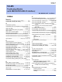
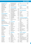
CONTENTS
Applicable Product ....................................................................................i
Important ...................................................................................................ii
Introduction............................................................................................viii
Copyrights and Trademarks ...................................................................ix
1.
Overview ....................................................................................... 1-1
2.
Overview of Positioning Functions ............................................ 2-1
3.
4.
2.1
Positioning by Standard Servo Profile Commands ............................. 2-1
2.2
Positioning by Interpolation Motion Commands ................................. 2-6
Module Specifications ................................................................. 3-1
3.1
Specifications .......................................................................................... 3-1
3.2
Compatible External Devices and Cables............................................. 3-2
3.3
Scope of MECHATROLINK-III Support .................................................. 3-3
3.3.1
Profile Types.............................................................................. 3-3
3.3.2
Standard Servo Profile Commands ........................................... 3-4
3.3.3
Standard I/O Profile Commands................................................ 3-6
3.4
Components and Their Functions ......................................................... 3-7
3.5
External Dimensions ............................................................................... 3-8
3.6
Attaching/Detaching the Module............................................................ 3-9
3.7
Connecting to External Devices .......................................................... 3-11
Input/Output Relays, Parameters and Statuses......................... 4-1
4.1
List of Input/Output Relays .................................................................... 4-1
4.1.1
4.2
Input Relays............................................................................... 4-1
4.1.2
Output Relays ............................................................................ 4-2
4.1.3
Operation of Input/Output Relays .............................................. 4-3
List of Parameters and Statuses............................................................ 4-7
4.2.1
Module Information Statuses................................................... 4-10
4.2.2
MECHATROLINK-III Communication Parameters ...................4-11
4.2.3
Axis MECHATROLINK-III Command Parameters................... 4-14
4.2.4
Axis MECHATROLINK-III Response Parameters ................... 4-26
4.2.5
Axis Statuses ........................................................................... 4-28
4.2.6
4.2.7
Common Statuses ................................................................... 4-35
Extended MECHATROLINK-III Command and Response
Parameters .............................................................................. 4-38
IM 34M06H60-03E
1st Edition : Jan. 2010-00
TOC-2
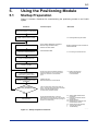
5.
Using the Positioning Module ..................................................... 5-1
5.1
Startup Preparation ................................................................................. 5-1
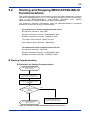
5.2
Starting and Stopping MECHATROLINK-III Communications ............ 5-2
5.3
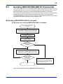
Sending MECHATROLINK-III Commands ............................................. 5-6
5.3.1
5.3.2
6.
7.
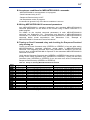
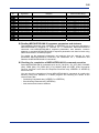
Parameters and Statuses of MECHATROLINK-III Commands...... 5-28
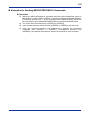
Example of MECHATROLINK-III Command Format
Conversion .............................................................................. 5-36
5.4
Executing Interpolation Motion Commands....................................... 5-40
Parameters and Statuses of Interpolation Motion
5.4.1
Commands .............................................................................. 5-51
5.5
Reading Statuses .................................................................................. 5-53
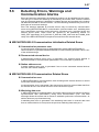
5.6
Detecting Errors, Warnings and Communication Alarms ................. 5-57
5.7
Clearing Errors and Warnings.............................................................. 5-61
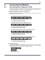
Accessing the Module ................................................................. 6-1
6.1
Accessing from Sequence CPU............................................................. 6-1
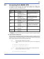
6.2
Accessing from BASIC CPU................................................................... 6-2
6.3
Precautions When Reading 2-word Data .............................................. 6-3
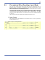
Troubleshooting ........................................................................... 7-1
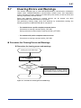
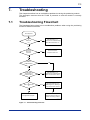
7.1
Troubleshooting Flowchart .................................................................... 7-1
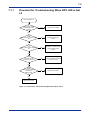
7.1.1
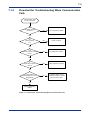
7.1.2
7.2
Flowchart for Troubleshooting When RDY LED is Not Lit ......... 7-2
Flowchart for Troubleshooting When Communication
Fails ........................................................................................... 7-3
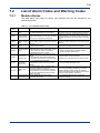
List of Alarm Codes and Warning Codes.............................................. 7-4
7.2.1
Module Alarms........................................................................... 7-4
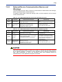
7.2.2
External Device Communication Alarms and Warnings ............ 7-5
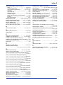
Index ...............................................................................................Index-1
Revision Information .................................................................................i
IM 34M06H60-03E
1st Edition : Jan. 2010-00
1-1
1.
Overview
This positioning module is to be installed in the base unit of a FA-M3 range free
controller system, and supports MECHATROLINK-III communications.
What is MECHATROLINK-III Communications?
Overview
MECHATROLINK-III communications is a high performance, advanced, openarchitecture motion field network standard published by the MECHATROLINK Members
Association. It enables distributed control of multiple FA units (servo drives, inverters, I/O
modules, etc.) by one FA controller.
With higher communication specification than its predecessors, namely
MECHATROLINK-I of 4 Mbps transmission rate and MECHATROLINK-II of 10 Mbps
transmission rate, MECHATROLINK-III features higher speed and more functions.
MECHATROLINK-III has the following features:
- Synchronous communication through cyclic transmission
- High speed transmission at 100 Mbps
- Communication cycle time options allow optimization based on the number of
connected stations and transmission data size. (This module provides three
communication cycle time options: 0.25 ms for 4 axes, 0.5 ms for 8 axes and 1 ms
for 15 axes.)
- Reduced wiring at low cost through the use of standard Ethernet cables between
external devices.
- Lower FA controller load as transmission control by the proprietary Communication
ASIC includes error detection and retransmission within a communication cycle.
- Allows a FA controller acting as master to connect to other FA support tools.
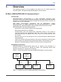
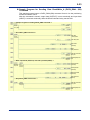
Network Connection
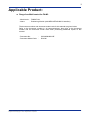
MECHATROLINK-III communications allows one C1 master to be connected to a
maximum of 62 slaves and an optional C2 master. (The positioning module itself
supports connection to a maximum of 15 slaves.)
Figure 1.1 shows the network connection for MECHATROLINK-III communications.
C1 Master
station
(FA Controller)
C2 Master
station
(Support tool)
No.1
Slave station
(FA unit)
No.2
Slave station
(FA unit)
No.3
Slave station
(FA unit)
No.62
....
Slave station
(FA unit)
F010101.VSD
Figure 1.1 Network Connections for MECHATROLINK-III Communications
IM 34M06H60-03E
1st Edition : Jan. 2010-00
1-2
Module Features
The positioning module provides the C1 master function of the MECHATROLINK-III
communications, transmitting MECHATROLINK-III commands to external devices
(slaves) according to the instructions from a CPU module and receiving
MECHATROLINK-III responses from external devices.
The module enables:
(1) Independent axis motion using MECHATROLINK-III commands
(2) Linear interpolation motion (starting and stopping multiple axes simultaneously)
(3) Reading target positions, current positions and other statuses of external devices
(4) Reading and writing parameters of external devices
(5) External device I/O
The module has the following features:
Latest open motion field network
-
MECHATROLINK-III is a high-performance, advanced, open-architecture motion
field network standard published by the MECHATROLINK Members Association. It
adopts proven Ethernet as its physical layer.
Fewer cables, simpler configuration, lower wiring cost
-
The module implements position control for up to 15 axes from a single slot.
Controllers and motors can be connected using fewer cables terminated with easyto-attach connectors, contributing to lower wiring cost.
High-speed, accurate position control through high-speed, highthroughput communication
-
-
High transmission rate of 100 Mbps and short cycle time of 0.25, 0.5, or 1 ms for 4-,
8-, or 15-axis control respectively enable shorter control cycle, faster startup, better
control performance, shorter tact time, and higher productivity.
Up to 8 monitor data (target position, current position, speed, torque, etc.) per axis
can be read simultaneously for better monitoring of external device operation.
Control by transmitted commands enables full exploitation of motor performance
(high speed and high resolution) to achieve fast and accurate position control.
Versatile position control includes linear interpolation motion of up to 15 axes
(starting and stopping multiple axes simultaneously), simultaneous linear
interpolation motion of any combination of axes, and change of speed or target
position during motion.
Flexible system configuration
-
Cascade and star network topologies with inter-station distance up to 100 m are
supported, enabling optimal system configuration.
More compatible external devices upcoming
-
In addition to AC servomotors from Yaskawa Electric Corporation, stepping motors,
external I/O equipment, and inverters from other manufacturers will be supported in
the future.
IM 34M06H60-03E
1st Edition : Jan. 2010-00
1-3
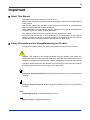
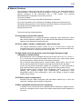
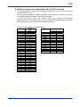
Module Operation
Figure 1.2 shows the principle behind the operation of the positioning module.
Independent axis motion using MECHATROLINK-III commands
The procedure for initiating a positioning motion by sending a MECHATROLINK-III
command is given below.
- From the CPU module, a program writes the command code ($35) for the
positioning command (POSING: $35), as well as other command parameters such
as target position (reference unit) and target speed (reference unit/s) to the
command parameters area.
- After writing completes, the program turns on the Send Command output relay. The
corresponding MECHATROLINK-III command is transmitted to the external device
(e.g. servo drive) to initiate the desired positioning motion in the external device.
- The Response Received input relay turns on when a response to the transmitted
MECHATROLINK-III command is received.
- The Positioning Completed input relay turns on subsequently when the positioning
motion completes.
Linear interpolation motion (starting and stopping multiples axes
simultaneously)
The procedure for performing linear interpolation is given below.
- From the CPU module, a program writes the command code ($100) and other
command parameters for the interpolation motion command such as acceleration
time (in ms), deceleration time (in ms), and interpolation axes, as well as the target
position (reference unit) and target speed (reference unit/s) of each motion axis to
the command parameters area.
- After writing completes, the program turns on the Send Command output relay. The
module computes the target position at each communication cycle, and transmits
the computed target position to all external devices involved in the linear
interpolation motion simultaneously using MECHATROLINK-III commands to initiate
the desired positioning motion.
- The Response Received input relay turns on when positioning motion begins.
- The Positioning Completed input relay turns on subsequently when positioning
motion completes.
Positioning module (F3NC97-0N)
CPU module
Input relays
Output relays
Communication parameters
Ladder
program
Command parameters
MECHATROLINK-III
commands
(for 15 axes)
MECHATROLINK-III
responses
(for 15 axes)
Path
generation
MECHATROLINK-III
command
External device (servo driver)
Positioning
Position/speed
servo
computation
Motor
MECHATROLINK-III
response
Encoder
F010102.VSD
Figure 1.2 Operating Principle of the Positioning Module
IM 34M06H60-03E
1st Edition : Jan. 2010-00
1-4
Machine fault or misoperation may cause a motor to behave in an unexpected manner.
All motors should be wired according to manufacturers’ recommendations to allow
external power shutdown and emergency stop.
IM 34M06H60-03E
1st Edition : Jan. 2010-00
2-1
2.
Overview of Positioning Functions
The positioning module (with MECHATROLINK-III Interface) provides positioning by
MECHATROLINK-III standard servo profile commands and positioning by interpolation
motion commands. The module implements the latter by computing and sending
position references required for implementing an interpolation motion.
2.1
Positioning by Standard Servo Profile
Commands
This section gives an overview of positioning by MECHATROLINK-III standard servo
profile commands executable by the module.
For details on the operation of each of these commands, as well as other
MECHATROLINK-III standard servo profile commands, refer to the technical
documentation published by the MECHATROLINK Members Association (MMA) or user
manuals published by Yaskawa Electric Corporation, as listed in the tables below.
Table 2.1 List of MECHATROLINK-III Technical Documents
published by the MECHATROLINK Members Association
Document Name
Document Number
MECHATROLINK-III Overview
MECHATROLINK-III Protocol Specifications
MLC07-003
MMATDEP020A
MECHATROLINK-III Command
Specifications for Standard Servo Profile
MECHATROLINK-III Command
Specifications for Standard I/O Profile
MMATDEP021A
MMATDEP022A
Description
Gives an overview of MECHATROLINK-III.
Describes the physical layer, data link layer and
application layer of MECHATROLINK-III.
Describes the MECHATROLINK-III command
specifications for standard servo profile.
Describes the MECHATROLINK-III command
specifications for standard I/O profile.
Note: MECHATROLINK Members Association (MMA) membership is required for accesing technical documentation
published by MMA.
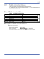
Table 2.2 List of Manuals for MECHATROLINK- III Compatible Products
manufactured by Yaskawa Electric Corporation
Document Number
Description
AC Servodrive Σ -V Series USER’S
MANUAL: Design and Maintenance
(Rotational Motor MECHATROLINK-III
Command Option Type)
Document Name
SIEP S800000 64A
Describes information required for design and
maintenance for the Σ -V Series SERVOPACK
(Rotational Motor MECHATROLINK-III Command Option
Type)
AC Servodrive Σ -V Series USER’S
MANUAL: Design and Maintenance
(Linear Motor MECHATROLINK-III
Command Option Type)
SIEP S800000 65A
Describes information required for design and
maintenance for the Σ -V Series SERVOPACK (Linear
Motor MECHATROLINK-III Command Option Type)
AC Servodrive Σ -V Series USER’S
MANUAL: MECHATROLINK-III
Standard Servo Profile Commands
SIEP S800000 63A
Describes the specifications of standard servo profile
commands used in MECHATROLINK-III communication
for the Σ -V Series SERVOPACK
IM 34M06H60-03E
1st Edition : Jan. 2010-00
2-2
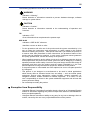
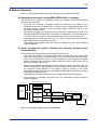
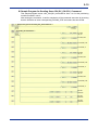
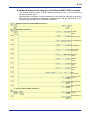
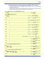
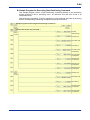
Positioning Command (POSING: $35)
The POSING command is used to execute positioning to a specified position.
Positioning is executed to the target position (P1) at the positioning speed.
To cancel a POSING command execution, set SVCMD_CTRL.CMD_CANCEL (the
CMD_CANCEL bit of the Servo Command Control Field) to 1 and re-execute the
POSING
command;
to
pause
a
POSING
command
execution,
set
SVCMD_CTRL.CMD_PAUSE to 1 and re-execute the POSING command.
Confirm the completion of motion reference output by checking that SVCMD_IO.DEN
= 1, and the completion of positioning by checking that SVCMD_IO.PSET = 1.
To change the speed during motion or change the target position during motion, change
the command value and re-execute the POSING command.
If the new position provides inadequate allowance for the deceleration distance, or if the
new position is in the reverse direction relative to the current motion direction, the
motion is decelerated to a stop before positioning to the new position.
Speed
Positioning speed
Time
P1
(Target position)
F020101.VSD
Figure 2.1 Operation Example for Positioning Command (POSING: $35)
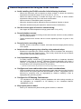
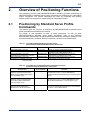
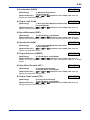
Feed Command (FEED: $36)
The FEED command is used to perform constant speed feed control at a specified feed
speed.
To cancel a FEED command execution, set SVCMD_CTRL.CMD_CANCEL (the
CMD_CANCEL bit of the Servo Command Control Field) to 1 and re-execute the FEED
command; to pause a FEED command execution, set SVCMD_CTRL.CMD_PAUSE to 1
and re-execute the FEED command.
Confirm the completion of motion reference output by checking that SVCMD_IO.DEN
= 1, and the completion of positioning by checking that SVCMD_IO.PSET = 1.
To change the speed and/or direction during motion, change the feed speed setting and
re-execute the FEED command. If a direction change is required, the motion is
decelerated to a stop before operation is initiated in the reverse direction.
Speed
Feed speed
SVCMD_CTRL.CMD_CANCEL=1
Time
F020102.VSD
Figure 2.2 Operation Example for Feed Command (FEED:$36)
IM 34M06H60-03E
1st Edition : Jan. 2010-00
2-3
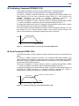
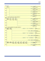
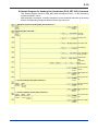
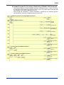
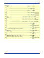
External Input Feed Command (EX_FEED: $37)
The EX_FEED command performs positioning in response to the input of the external
positioning signal during constant speed feed at the specified feed speed.
When the external positioning signal is input during constant speed feed, the current
position counter (P2) is latched, and motion is then decelerated to a stop at position P3
by traveling through the external positioning final travel distance specified by a
parameter.
If the travel distance required for deceleration to a stop is longer than the specified
external positioning final travel distance, the motion is first decelerated to a stop
according to the deceleration pattern, and then a return to the target position is executed
before command execution ends.
The external signal used to latch the current position is specified by
SVCMD_CTRL.LT_SEL.
To cancel an EX_FEED command execution, set SVCMD_CTRL.CMD_CANCEL (the
CMD_CANCEL bit of the Servo Command Control Field) to 1 and re-execute the
EX_FEED command; to pause an EX_FEED command execution, set
SVCMD_CTRL.CMD_PAUSE to 1 and re-execute the EX_FEED command.
Confirm the completion of motion reference output by checking that SVCMD_IO.DEN
= 1, and the completion of positioning by checking that SVCMD_IO.PSET = 1.
To change the speed and/or direction during motion, change the speed feed setting and
re-execute the EX_FEED command. If a direction change is required, the motion is
decelerated to a stop before operation is initiated in the reverse direction.
Speed
Feed speed
P2
(Latched position data)
External
positioning
final travel
distance
P3
Time
External Positioning signal
F020103VSD
Figure 2.3 Operation Example for External Input Feed Command (EX_FEED: $37)
(Positioning after Latching)
Speed
Feed speed
SVCMD_CTRL.CMD_CANCEL=1
Time
External positioning signal
F020104.VSD
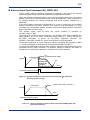
Figure 2.4
Operation Example for External Input Feed Command (EX_FEED: $37)
(Interrupted Operation)
IM 34M06H60-03E
1st Edition : Jan. 2010-00
2-4
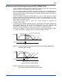
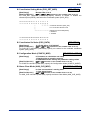
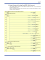
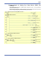
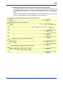
External Input Positioning Command (EX_POSING: $39)
The EX_POSING command performs positioning in response to the input of the external
positioning signal during positioning to a specified position.
When the external positioning signal is input during positioning to a specified position
(P1), the current position counter (P2) is latched, and motion is then decelerated to a
stop at position P3 by traveling through the external positioning final travel distance
specified by a parameter.
If the travel distance required for deceleration to a stop is longer than the specified
external positioning final travel distance, the motion is first decelerated to a stop
according to the deceleration pattern, and then a return to the target position is executed
before command execution ends.
The external signal used to latch the current position is specified by
SVCMD_CTRL.LT_SEL.
To cancel an EX_POSING command execution, set SVCMD_CTRL.CMD_CANCEL (the
CMD_CANCEL bit of the Servo Command Control Field) to 1 and re-execute the
EX_POSING command; to pause an EX_POSING command execution, set
SVCMD_CTRL.CMD_PAUSE to 1 and re-execute the EX_POSING command.
Confirm the completion of motion reference output by checking that SVCMD_IO.DEN
= 1, and the completion of positioning by checking that SVCMD_IO.PSET = 1.
P2 (Latched position data)
Speed
Feed speed
P3
External
positioning
final travel
distance
P1
Time
External positioning signal
F020105.VSD
Figure 2.5 Operation Example for External Input Positioning Command (EX_POSING: $39)
(Positioning after Latching)
Speed
Feed speed
P2
P4
P3
P1
Time
External positioning signal
External positioning final travel distance
* Position is the integral of speed reference
F020106.VSD
Figure 2.6 When Motion Cannot be Decelerated to a Stop
Using the Specified External Positioning Final Travel
IM 34M06H60-03E
1st Edition : Jan. 2010-00
2-5
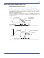
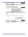
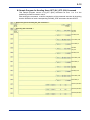
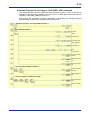
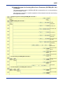
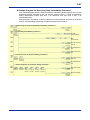
Zero Point Return Command (ZRET: $3A)
The ZRET command is used to perform a zero point return operation using the zero
point limit switch and the position latch signal.
The signal used to latch the position is specified by SVCMD_CTRL.LT_SEL.
The zero point return direction and zero point return type is specified by MODE.
To cancel a ZRET command execution, set SVCMD_CTRL.CMD_CANCEL (the
CMD_CANCEL bit of the Servo Command Control Field) to 1 and re-execute the ZRET
command; to pause a ZRET command execution, set SVCMD_CTRL.CMD_PAUSE to 1
and re-execute the ZRET command.
Confirm the completion of motion reference output by checking that SVCMD_IO.DEN
= 1, and the completion of positioning by checking that SVCMD_IO.ZPOINT=1 and
SVCMD_IO.PSET = 1.
Speed
Approach speed
Final travel distance
for zero point return
Creep
speed
Zero point
Time
Position latch signal
F020107.VSD
Figure 2.7 Operation Example for Zero Point Return Command (ZRET: $3A) (When MODE=0)
Speed
Feed speed
Final travel distance
for zero point return
Approach
speed
Creep
speed
Zero point
Time
Deceleration
limit switch
Open
Close
Position latch signal
F020108.VSD
Figure 2.8 Operation Example for Zero Point Return Command (ZRET: $3A) (When MODE=1)
IM 34M06H60-03E
1st Edition : Jan. 2010-00
2-6
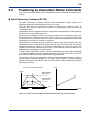
2.2
Positioning by Interpolation Motion Commands
This section describes positioning by interpolation motion commands executable by the
module.
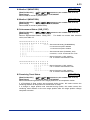
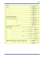
Start Positioning Command ($0100)
The Start Positioning command executes linear interpolation motion (starting and
stopping multiples axes simultaneously) for up to 15 axes.
The axis from which the command is issued is known as the "reference axis" (or
command axis), while the other axes involved in the interpolation motion are known as
"interpolation axes".
Interpolation axes are specified using the Interpolation Axes parameter of the reference
axis at the time of command execution.
While a linear interpolation motion is in progress, another linear interpolation motion can
be executed using a different set of axes, which are at rest. Up to 15 axes can be made
to move this way. Concurrent execution of two or more linear interpolation motions with
overlapping sets of axes is, however, not allowed.
Target position and speed must be specified for each motion axis (reference axis and
interpolation axes). In order that all motion axes can stop at the same time, this module
computes the attained speed of each axis to accommodate the axis that requires the
longest travel time (as detected by the module). Each axis then moves according to its
attained speed, regardless of its preset speed.
To stop a linear interpolation motion, execute a Decelerate and Stop command ($0200)
or a Stop Immediately command ($0300) against the reference axis, which is the axis
from which the Start Positioning command was originally issued.
To change the speed or target position during a linear interpolation motion, execute a
Change Speed command ($0400) or a Change Target Position command ($0500)
against the reference axis, which is the axis from which the Start Positioning command
was originally issued.
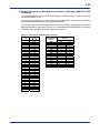
2-axis Linear Interpolation Motion
Speed
Y-axis
Speed attained
along X-axis
P1
X-axis travel
Speed attained
along Y-axis
Y-axis travel
Time
Acceleration time
P0
X-axis
Deceleration time
F020201.VSD
Figure 2.9 Linear Interpolation Motion Initiated by Start Positioning Command ($0100)
IM 34M06H60-03E
1st Edition : Jan. 2010-00
2-7
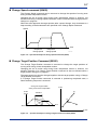
Change Speed command ($0400)
The Change Speed command can be executed to change the speeds of moving axes
during a linear interpolation motion.
Changing the set of motion axes during linear interpolation motion is, however, not
allowed. Executing a Change Speed command is also not allowed while a target position
change is in progress.
When the axes approach the target position after a speed change, they decelerate to a
stop according to the deceleration time specified in the Change Speed command.
Speed
Start
Request to
change speed
Time
Request to
change speed
F020202.VSD
Figure 2.10 Operation Example fof Change Speed Command ($0400)
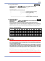
Change Target Position Command ($0500)
The Change Target Position command is executed to change the target positions of
moving axes during a linear interpolation motion.
Changing the set of motion axes during linear interpolation motion is, however, not
allowed. Execution of a Change Target Position command is also not allowed while a
target position change is in progress.
The target speed can also be changed together with the target position using a Change
Target Position Command.
If a Change Target Position command is executed in 'positioning completed' state, a
Start Positioning sequence is executed.
Change in Target Position
during 2-axis Linear Interpolation
X-axis
speed
Y-axis
P1
Transition
P1'
Start
Start
P2
Time
P0
X-axis
F020203.VSD
Figure 2.11
Operation Example for Change Target Position Command ($0500)
IM 34M06H60-03E
1st Edition : Jan. 2010-00
Blank Page
3-1
3.
Module Specifications
3.1
Specifications
Model Name and Suffix Code
Table 3.1 Model Name and Suffix Code
Model
Suffix Code
Style Code
Option
Code
F3NC97
-0N
......
......
Description
Controls up to 15 axes
with MECHATROLINK-III interface
Operating Environment
This module is compatible with the following CPU modules.
Table 3.2 CPU Module Restrictions
CPU Module
F3SP28-3N, F3SP38-6N
F3SP53-4H, F3SP58-6H
Other CPUs
Style Code and ROM Version
Rev. 7 or later
No restriction
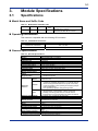
General Specifications
Table 3.3 General Specifications
Item
Interface
Physical layer
Transmission rate
Cycle time / No. of stations
Transmission bytes
Communications method
Network topology
Transmission media
Maximum transmission distance
Minimum distance between
stations
Specifications
MECHATROLINK-III compliant
Ethernet
100 Mbps
0.25 ms for 4 axes, 0.5 ms for 8 axes, or 1.0 ms for 15 axes
16, 32, 48, or 64 bytes (intermixing allowed)
Cyclic communication
Cascade or star
Ethernet STP Cat5e (dedicated cable)
100 m (between stations)
Supported profiles
- Standard servo profile
- Standard I/O profile
-2,147,483,648 to 2,147,483,647
(reference unit)
- Independent axis motion using standard servo profile
commands (availability dependent on connected external
device and supported standard servo profile commands)
- Linear interpolation motion (starting and stopping multiple
axes simultaneously)
and speed/target position change during motion
- Status monitoring of external devices
(target position, current position, speed, and torque)
- Reading and writing parameters of external devices
- External device I/O using standard I/O profile commands
8 modules max. (controlling 120 axes max.)
530 mA (at 5 V DC)
Two MECHATROLINK-III connectors
(industrial mini-connector)
28.9 (W) × 100 (H) × 83.2 (D) mm *
130 g
0 to 55C
10 to 90% RH (non-condensing)
Must be free of corrosive gases, flammable gases and heavy
dust
-20 to 75C
10 to 90% RH (non-condensing)
Position
reference
Positioning
functions
Functions
Others
Number of installed modules
Current consumption
External connection
External dimensions
Weight
Operating ambient temperature
Operating ambient humidity
Operating ambient atmosphere
Storage ambient temperature
Storage ambient humidity
0.2 m
*: Excluding protrusions (for details, see external dimensions drawing)
IM 34M06H60-03E
1st Edition : Jan. 2010-00
3-2
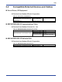
3.2
Compatible External Devices and Cables
Servo Drives, I/O Equipment
Products from Yaskawa Electric Corporation
Table 3.4 Servo Drives, I/O Equipment
Product
AC Servo Drive Σ-V Series
MECHATROLINK-III Command Option type
SERVOPACK
64-point I/O module
Model
Description
SGDV-2
JEPMC-MTD2310-E
MECHATROLINK-III Communications Cable
Products from Yaskawa Controls Co., Ltd.
Table 3.5 MECHATROLINK-III Communications Cable
Product
MECHATROLINK-III communications cable
Model
JEPMC-W6012--E
JEPMC-W6013--E
JEPMC-W6014--E
Description
No core
With core
No core;
no connector on the other
end
MECHATROLINK-III Dedicated Hub
Products from Yaskawa Electric Corporation
Table 3.6 MECHATROLINK-III Dedicated Hub
Product
MECHATROLINK-III compatible hub module
Model
JEPMC-MT2000-E
Description
IM 34M06H60-03E
1st Edition : Jan. 2010-00
3-3
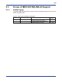
3.3
Scope of MECHATROLINK-III Support
3.3.1
Profile Types
The profile types supported by the module and the corresponding data size in bytes are
listed in the table below.
Table 3.7 Profile Type and Number of Data Bytes
Profile Code
$10
$30
Profile
Standard servo profile
Standard I/O profile
Description
Profile supported by MECHATROLINK-III
compliant standard servo products
Profile supported by MECHATROLINK-III
compliant standard I/O products
IM 34M06H60-03E
Data Size
(bytes)
32 or 48
16, 32, 48
or 64
1st Edition : Jan. 2010-00
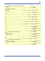
3-4
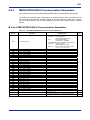
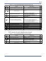
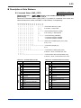
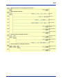
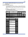
3.3.2
Standard Servo Profile Commands
This section lists the MECHATROLINK-III standard servo profile commands that are
executable by the module.
◎: Executable by a user using MECHATROLINK-III command parameters of each
axis.
○: Executable by a user using extended MECHATROLINK-III command parameters.
△: Not executable by a user but is executed automatically by the positioning module
or external device.
×: Not supported
Standard Servo Profile Main Commands
Table 3.8 Standard Servo Profile Main Command List
Profile
Common
commands
Standard
servo
Command
Code
$00
$01
$02
$03
$04
$05
$06
$0D
$0E
$0F
$1B
$1C
$1D
$1E
$20
$21
$22
$23
$24
$30
$31
$32
$34
$35
$36
$37
$39
$3A
$3C
$3D
$40
$41
Command
NOP
PRM_RD
PRM_WR
ID_RD
CONFIG
ALM_RD
ALM_CLR
SYNC_SET
CONNECT
DISCONNECT
PPRM_RD
PPRM_WR
MEM_RD
MEM_WR
POS_SET
BRK_ON
BRK_OFF
SENS_ON
SENS_OFF
SMON
SV_ON
SV_OFF
INTERPOLATE
POSING
FEED
EX_FEED
EX_POSING
ZRET
VELCTRL
TRQCTRL
SVPRM_RD
SVPRM_WR
Function
Communication Type
Supported
A
A
A
A
A
A
A
A
A
A
A
A
A
A
A
A
A
A
A
A
A
A
S
A
A
A
A
A
A
A
A
A
◎
×*1
×*1
○
◎
○
◎
◎
△
△
×*1
×*1
○
○
◎
◎*2
◎*2
◎
◎
◎
◎
◎
△
◎
◎
◎
◎
◎
◎
◎
◎
◎
No operation
Read parameter
Write parameter
Read ID
Setup device
Read alarm or warning
Clear alarm or warning
Start synchronous communication
Establish connection
Release connection
Read stored parameter
Write stored parameter
Read memory
Write memory
Set coordinates
Apply brake
Release brake
Turn sensor ON
Turn sensor OFF
Servo status monitor
Servo ON
Servo OFF
Interpolation
Positioning
Feed
External input feed
External input positioning
Zero point return
Velocity control
Torque control
Read servo parameter
Write servo parameter
*1: The standard servo command profile does not use PRM_RD, PRM_WR, PPRM_RD and PPRM_WR, but uses
SVPRM_RD and SVPRM_WR instead.
*2: Brake ON/OFF should be controlled by an external device n tandem with Servo ON/OFF commands.
Table 3.9 Communication Type
Symbol
S
A
Communication Type
Synchronous communication command
Asynchronous communication command
IM 34M06H60-03E
1st Edition : Jan. 2010-00
3-5
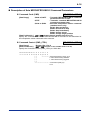
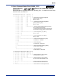
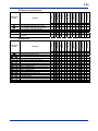
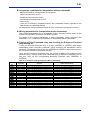
Standard Servo Profile Subcommands
Table 3.10 Standard Servo Profile Subcommand List
Profile
Standard
servo
Command
Code
$00
$01
$02
$05
$06
$1B
$1C
$1D
$1E
$30
$40
$41
Command
NOP
PRM_RD
PRM_WR
ALM_RD
ALM_CLR
PPRM_RD
PPRM_WR
MEM_RD
MEM_WR
SMON
SVPRM_RD
SVPRM_WR
Function
Supported
No operation
Read parameter
Write parameter
Read alarm or warning
Clear alarm or warning
Read stored parameter
Write stored parameter
Read memory
Write memory
Servo status monitor
Read servo parameter
Write servo parameter
△
×*1
×*1
×
×
×*1
×*1
×
×
△
×
×
*1: The standard servo command profile does not use PRM_RD, PRM_WR, PPRM_RD and PPRM_WR, but uses
SVPRM_RD and SVPRM_WR instead.
IM 34M06H60-03E
1st Edition : Jan. 2010-00
3-6
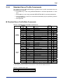
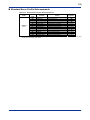
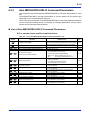
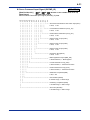
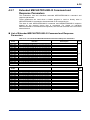
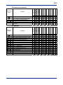
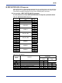
3.3.3
Standard I/O Profile Commands
This section lists the MECHATROLINK-III standard I/O profile commands that are
executable by the module.
◎: Executable by a user using MECHATROLINK-III command parameters of each
axis.
○: Executable by a user using extended MECHATROLINK-III command parameters.
△: Not executable by a user but is executed automatically by the positioning module
or external devices.
×: Not supported
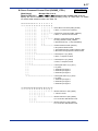
Standard I/O Profile Commands
Table 3.11
List of Standard I/O Profile Commands
Profile
Common
commands
Standard I/O
Command
Code
$00
$01
$02
$03
$04
$05
$06
$0D
$0E
$0F
$1B
$1C
$1D
$1E
$20
$21
Command
Function
Communication Type
Supported
NOP
PRM_RD
PRM_WR
ID_RD
CONFIG
ALM_RD
ALM_CLR
SYNC_SET
CONNECT
DISCONNECT
PPRM_RD
PPRM_WR
MEM_RD
MEM_WR
DATA_RWA
DATA_RWS
No operation
Read parameter
Write parameter
Read ID
Setup device
Read alarm or warning
Clear alarm or warning
Start synchronous communication
Establish connection
Release connection
Read stored parameter
Write stored parameter
Read memory
Write memory
Data Read/write_a
Data Read/write_s
A
A
A
A
A
A
A
A
A
A
A
A
A
A
A
S
◎
×
×
○
◎
○
◎
×
△
△
×
×
×
×
◎
×
Table 3.12 Communication Type
Symbol
S
A
Communication Type
Synchronous communication command
Asynchronous communication command
IM 34M06H60-03E
1st Edition : Jan. 2010-00
3-7
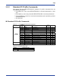
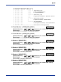
3.4
Components and Their Functions
Appearance and Construction
The outer appearance of the module is shown in the figure below.
RDY
CON
WRN
ERR
NC97-0N
PO SIT
LED indicators
LNK1 LED
MECHATROLINK-III connector 1
LNK2 LED
MECHATROLINK-III connector 2
F030401VSD
Figure 3.1 Appearance and Part Names
Component Functions
LED Indicators
The various LED indicators turn on or turn off to indicate the operating status of the
module.
Table 3.13 LED Indicators
Name
RDY
CON
(color)
(green)
(green)
WRN
ALM
(yellow)
(red)
Description
Status of internal circuitry
MECHATROLINK-III
communication status
Warning status
Error status
Lit
Normal
Communicating
Warning detected
Error detected
Not Lit
Error
Not
communicating
No warning
No error
LNK1 LED, LNK2 LED
The LNK1 and LNK2 LED indicators are lit when an external device is connected to the
LNK1 and LNK2 connectors respectively.
IM 34M06H60-03E
1st Edition : Jan. 2010-00
3-8
MECHATROLINK-III Connectors 1 and 2
These connectors are used for connecting MECHATROLINK-III compliant external
devices.
The table below shows the pin assignments for the module’s MECHATRONLINK IIII
connectors used for attaching MECHATROLINK-III compliant external devices.
Table 3.14 MECHATROLINK-III Connector Specifications
Pin No.
1
2
3
4
5
6
7
8
Signal
TXP
TXN
RXP
-
-
RXN
-
-
Function
Send data (+)
Send data (-)
Receive data (+)
Receive data (-)
Note: The connector shell is connected to the FG terminal.
These signal lines are isolated from the internal circuitry by pulse transformers.
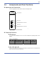
3.5
External Dimensions
Unit: mm
RDY
CON
WRN
ERR
NC97 -0N
P OSIT
F030402VSD
Figure 3.2 External Dimensions Drawing
IM 34M06H60-03E
1st Edition : Jan. 2010-00
3-9
3.6
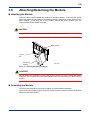
Attaching/Detaching the Module
Attaching the Module
Figure 3.3 shows how to attach this module to the base module. First hook the anchor
slot at the bottom of the module to be attached onto the anchor pin on the bottom of the
base module. Push the top of the module toward the base module until the
anchor/release button clicks into place.
CAUTION
Always switch off the power before attaching or detaching the module.
Base Module
Anchor
pin
Positioning
Module
F01.VSD
Figure 3.3 Attaching/Detaching the Module
CAUTION
Do not bend the connector on the rear of the module by force during the above
operation. If the module is pushed with improper force, the connector may bend causing
an error.
Detaching the Module
To remove this module from the base module, reverse the above operation.
Press the anchor/release button on the top of this module to unlock it and tilt the module
away from the base module.
IM 34M06H60-03E
1st Edition : Jan. 2010-00
3-10
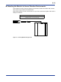
Attaching the Module in Intense Vibration Environments
If the module is used in intense vibration environments, fasten the module with a screw.
Use screws of type listed in the table below.
Insert these screws into the screw holes on top of the module and tighten them with a
Phillips screwdriver.
Required Screw
Binding head machine screw M4 of 12 to 15 mm long
(washer screw of 14-15 mm long)
F02R1.VSD
Figure 3.4 Securing Module Using Screws
IM 34M06H60-03E
1st Edition : Jan. 2010-00
3-11
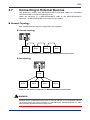
3.7
Connecting to External Devices
The positioning module uses MECHATROLINK-III dedicated cables for connecting
MECHATROLINK-III compliant external devices.
Attach the connector of a MECHATROLINK-III cable to the MECHATROLINK-III
connector 1 or MECHATROLINK-III connector 2 of the module.
Network Topology
Both cascade and star network configurations are supported.
Cascade topology
Slave
Slave
Slave
Slave
F030701.VSD
Figure 3.5 Cascade Network Configuration for MECHATROLINK-III Communications
Star topology
HUB
Slave
Slave
Slave
Slave
F030702.VSD
Figure 3.6 Star Network Configuration for MECHATROLINK-III Communications
WARNING
Machine fault or misoperation may cause a motor to behave in an unexpected manner.
All motors should be wired according to manufacturers’ recommendations to allow
external power shutdown and emergency stop.
IM 34M06H60-03E
1st Edition : Jan. 2010-00
3-12
Precautions on Wiring of MECHATROLINK-III Cable
Observe the following precautions when wiring MECHATROLINK-III communication
cables.
Cable
Always use a MECHATROLINK-III dedicated cable for connection.
Inter-station cable length
All cables between stations must be kept within 0.2 m and 100 m long.
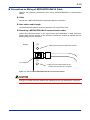
Detaching a MECHATROLINK-III communication cable
Follow the procedure shown in the figure below when detaching a cable connector.
Always slide the lock injector of the connector towards the module to release the lock
before pulling out the connector.
Module
(1)
1. Slide the lock injector towards the module.
(2)
Lock injector
2. With the lock injector slided to the
module side, pull out the connector.
F030703.VSD
Figure 3.7 How to Detach MECHATROLINK-III Communication Cables
Pulling out a cable connector without first releasing its lock may damage the connector.
IM 34M06H60-03E
1st Edition : Jan. 2010-00
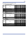
4-1
4.
Input/Output Relays, Parameters
and Statuses
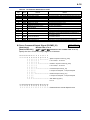
4.1
List of Input/Output Relays
This module provides 32 input relays and 32 output relays for interfacing with the CPU
module of a FA-M3 system.
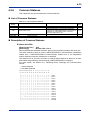
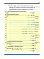
4.1.1
Input Relays
Figure 4.1 shows a list of input relays that are provided with the module.
Each input relay can be made to raise an interrupt signal to the CPU module when it
switches from OFF to ON.
In the table, "" denotes the FA-M3 slot number where the module is mounted.
Table 4.1 List of Input Relays
Input Relay
No.
X01
X02
X03
X04
X05
X06
X07
X08
X09
X10
X11
X12
X13
X14
X15
Signal Name
Description
Relation with Other Relays
AX1 Response Received
AX2 Response Received
AX3 Response Received
AX4 Response Received
AX5 Response Received
AX6 Response Received
AX7 Response Received
AX8 Response Received
AX9 Response Received
AX10 Response Received
AX11 Response Received
AX12 Response Received
AX13 Response Received
AX14 Response Received
AX15 Response Received
Turns on when a MECHATROLINK-III response for axis 1 is received.
Turns on when a MECHATROLINK-III response for axis 2 is received.
Turns on when a MECHATROLINK-III response for axis 3 is received.
Turns on when a MECHATROLINK-III response for axis 4 is received.
Turns on when a MECHATROLINK-III response for axis 5 is received.
Turns on when a MECHATROLINK-III response for axis 6 is received.
Turns on when a MECHATROLINK-III response for axis 7 is received.
Turns on when a MECHATROLINK-III response for axis 8 is received.
Turns on when a MECHATROLINK-III response for axis 9 is received.
Turns on when a MECHATROLINK-III response for axis 10 is received.
Turns on when a MECHATROLINK-III response for axis 11 is received.
Turns on when a MECHATROLINK-III response for axis 12 is received.
Turns on when a MECHATROLINK-III response for axis 13 is received.
Turns on when a MECHATROLINK-III response for axis 14 is received.
Turns on when a MECHATROLINK-III response for axis 15 is received.
Turning off Y33 also turns off this relay.
Turning off Y34 also turns off this relay.
Turning off Y35 also turns off this relay.
Turning off Y36 also turns off this relay.
Turning off Y37 also turns off this relay.
Turning off Y38 also turns off this relay.
Turning off Y39 also turns off this relay.
Turning off Y40 also turns off this relay.
Turning off Y41 also turns off this relay.
Turning off Y42 also turns off this relay.
Turning off Y43 also turns off this relay.
Turning off Y44 also turns off this relay.
Turning off Y45 also turns off this relay.
Turning off Y46 also turns off this relay.
Turning off Y47 also turns off this relay.
Turning on Y48 to initiate
communication turns on this relay when
communication begins.
Turning off Y48 also turns off this relay.
X16 Communication Status
Input Relay
No.
X17
X18
X19
X20
X21
X22
X23
X24
X25
X26
X27
X28
X29
X30
X31
Turns on while MECHATROLINK-III communication is in progress;
turns off otherwise.
Signal Name
AX1 Positioning Completed
AX2 Positioning Completed
AX3 Positioning Completed
AX4 Positioning Completed
AX5 Positioning Completed
AX6 Positioning Completed
AX7 Positioning Completed
AX8 Positioning Completed
AX9 Positioning Completed
AX10 Positioning Completed
AX11 Positioning Completed
AX12 Positioning Completed
AX13 Positioning Completed
AX14 Positioning Completed
AX15 Positioning Completed
X32 Error/Warning Detected
Description
Relation with Other Relays
Turns on when axis 1 is in positioning completed state.
Turns on when axis 2 is in positioning completed state.
Turns on when axis 3 is in positioning completed state.
Turns on when axis 4 is in positioning completed state.
Turns on when axis 5 is in positioning completed state.
Turns on when axis 6 is in positioning completed state.
Turns on when axis 7 is in positioning completed state.
Turns on when axis 8 is in positioning completed state.
Turns on when axis 9 is in positioning completed state.
Turns on when axis 10 is in positioning completed state.
Turns on when axis 11 is in positioning completed state.
Turns on when axis 12 is in positioning completed state.
Turns on when axis 13 is in positioning completed state.
Turns on when axis 14 is in positioning completed state.
Turns on when axis 15 is in positioning completed state.
Turning on Y64 to clear all errors
Turns on when an error or warning is detected by the module or
and warnings turns off this relay if errors
any axis.
and warnings are successfully cleared.
IM 34M06H60-03E
1st Edition : Jan. 2010-00
4-2
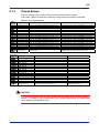
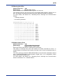
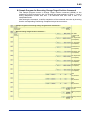
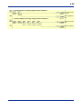
4.1.2
Output Relays
Figure 4.2 shows a list of output relays that are provided with the module.
In the table, "" denotes the FA-M3 slot number where the module is mounted.
Table 4.2 List of Output Relays
Output
Relay No.
Y33
Y34
Y35
Y36
Y37
Y38
Y39
Y40
Y41
Y42
Y43
Y44
Y45
Y46
Y47
Signal Name
AX1 Send Command
AX2 Send Command
AX3 Send Command
AX4 Send Command
AX5 Send Command
AX6 Send Command
AX7 Send Command
AX8 Send Command
AX9 Send Command
AX10 Send Command
AX11 Send Command
AX12 Send Command
AX13 Send Command
AX14 Send Command
AX15 Send Command
Start/Stop
Y48
Communication
Output Relay
No.
Y49
Y50
Y51
Y52
Y53
Y54
Y55
Y56
Y57
Y58
Y59
Y60
Y61
Y62
Y63
Y64
Description
Request to send MECHATROLINK-III command for axis 1.
Request to send MECHATROLINK-III command for axis 2
Request to send MECHATROLINK-III command for axis 3
Request to send MECHATROLINK-III command for axis 4
Request to send MECHATROLINK-III command for axis 5
Request to send MECHATROLINK-III command for axis 6
Request to send MECHATROLINK-III command for axis 7
Request to send MECHATROLINK-III command for axis 8
Request to send MECHATROLINK-III command for axis 9
Request to send MECHATROLINK-III command for axis 10
Request to send MECHATROLINK-III command for axis 11
Request to send MECHATROLINK-III command for axis 12
Request to send MECHATROLINK-III command for axis 13
Request to send MECHATROLINK-III command for axis 14
Request to send MECHATROLINK-III command for axis 15
Request to start or stop MECHATROLINK-III
communication
Signal Name
Description
Relation with Other Relays
Turn off this relay after verifying that X01 has turned on.
Turn off this relay after verifying that X02 has turned on.
Turn off this relay after verifying that X03 has turned on.
Turn off this relay after verifying that X04 has turned on.
Turn off this relay after verifying that X05 has turned on.
Turn off this relay after verifying that X06 has turned on.
Turn off this relay after verifying that X07 has turned on.
Turn off this relay after verifying that X08 has turned on.
Turn off this relay after verifying that X09 has turned on.
Turn off this relay after verifying that X10 has turned on.
Turn off this relay after verifying that X11 has turned on.
Turn off this relay after verifying that X12 has turned on.
Turn off this relay after verifying that X13 has turned on.
Turn off this relay after verifying that X14 has turned on.
Turn off this relay after verifying that X15 has turned on.
X16 shows the current communication status.
Relation with Other Relays
(system reserved)
(system reserved)
(system reserved)
(system reserved)
(system reserved)
(system reserved)
(system reserved)
(system reserved)
(system reserved)
(system reserved)
(system reserved)
(system reserved)
(system reserved)
(system reserved)
(system reserved)
Clear Error/warning
Request to clear all errors and warnings
Turn off this relay after verifying that
X32 has turned off.
CAUTION
In a multi-CPU system, only one CPU module can be configured to use the positioning
module. For details on CPU configuration, see "FA-M3 Programming Tool WideField2
User's Manual" (IM34M06Q15-01E).
IM 34M06H60-03E
1st Edition : Jan. 2010-00
4-3
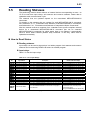
4.1.3
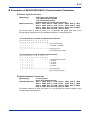
Operation of Input/Output Relays
Input Relays
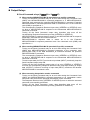
Response Received relays (X01 to X15)
(1) When sending MECHATROLINK-III (standard servo profile) commands
The Response Received relay of an axis turns on when a MECHATROLINK-III
response is received for a MECHATROLINK-III command, whose transmission is
initiated by a rising edge of the Send Command relay (Y33 to Y47) of
the axis.
To confirm that a response has been received, check that the command code
(RCMD) stored in the received MECHATROLINK-III response tallies with the
command code (CMD) of the transmitted MECHATROLINK-II command, and that
the axis is ready to receive commands (CMDRDY bit of CMD_STAT = 1).
Turning off the Send Command relay of an axis (Y33 to Y47) turns off
the corresponding Response Received relay.
(2) When sending MECHATROLINK-III (standard I/O profile) commands
If the command code (CMD) of the MECHATROLINK-III command parameters of an
axis is set to DATA_RWA ($20) for the Data Read/Write_A command and
transmission of the command is initiated by a rising edge of the Send Command
relay (Y33 to Y47) of the axis, the Response Received relay of the axis
turns on when a MECHATROLINK-III response is received for the transmitted
MECHATROLINK-III command.
While the Response Received relay is ON, output data (OUTPUT) is sent and input
data (INPUT) is received continually.
Turning off the Send Command relay of an axis (Y33 to Y47) turns off
the corresponding Response Received relay and stops sending of output data
(OUTPUT). However, receiving of input data (INPUT) continues until another
MECHATROLINK-III command is sent.
(3) When executing interpolation motion commands
The Response Received relay of an axis turns on to indicate normal processing of
an interpolation motion command, whose execution was initiated by a rising edge in
the Send Command relay (Y33 to Y47) of the axis.
Turning off the Send Command relay of an axis (Y33 to Y47) turns off
the corresponding Response Received relay.
Communication Status relay (X16)
The Communication Status relay turns on when MECHATROLINK-III communication
initialization, which was initiated by a rising edge in the Start/Stop Communication
relay (Y48), is successfully completed to indicate that the module is ready to
send and receive MECHATROLINK-III commands.
Turning off the Start/Stop Communication relay (Y48) to stop MECHATROLINK-III
communication also turns off this relay.
If MECHATROLINK-III communication initialization is not successful, this relay does
not turn on. If this happens, check the configuration and wiring of external devices,
as well as communication parameter values.
IM 34M06H60-03E
1st Edition : Jan. 2010-00
4-4
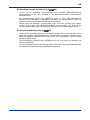
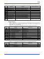
Positioning Completed relays (X17 to X31)
These relays are valid only for MECHATROLINK-III standard servo profile compliant
external devices. These relays are always OFF for MECHATROLINK-III standard I/O
profile compliant external devices.
(1) When sending MECHATROLINK-III commands
The Positioning Completed relay for an axis turns on when the axis is in Positioning
Completed state.
This relay turns off when a positioning motion, which is initiated by a
MECHATROLINK-III command, begins.
The relay turns on or turns off according to the Positioning Completed Status
(PSET) bit of SVCMD_IO of a MECHATROLINK-III response.
(2) When executing interpolation motion commands
The Positioning Completed relay for an axis turns on when the axis is in Positioning
Completed state.
This relay turns off when a positioning motion, which is initiated by an interpolation
motion command, begins.
After a positioning motion, which is initiated by an interpolation motion command, is
completed, the relay turns on or turns off according to the Positioning Completed
Status (PSET) bit of SVCMD_IO of the MECHATROLINK-III response.
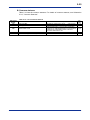
Error/Warning Detected relay (X32)
The Error/Warning Detected relay turns on when an error or warning is detected by
the module or any axis.
The relay turns off when all errors and warnings are cleared.
The relay turns on when CMD_STAT of a MECHATROLINK-III response received
from an external device indicates an alarm (CMD_STAT.D_ALM bit =1), a warning
(CMD_STAT.D_WAR bit =1), a command error code (CMD_STAT.CMD_ALM code
≠0) or a communication error code (CMD_STAT.COMM_ALM code ≠0). It also turns
on when the module detects a MECHATROLINK-III communication initialization
related error, a MECHATROLINK-III communication related error, or an interpolation
motion command execution related error.
To clear all reported errors and warnings, turn on the Clear Error/Warning relay
(Y64). If an error or warning condition persists even after the Clear
Error/Warning relay (Y64) is turned on, the Error/Warning Detected relay
remains ON.
For details on how to find out the cause of an error or warning when the
Error/Warning Detected relay is ON, see Section 5.6, "Detecting Errors, Warnings
and Communication Alarms".
IM 34M06H60-03E
1st Edition : Jan. 2010-00
4-5
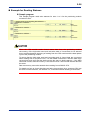
Output Relays
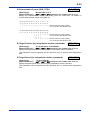
Send Command relays (Y33 to Y47)
(1) When sending MECHATROLINK-III (standard servo profile) commands
Turning on the Send Command relay for an axis after setting the Command Code
(CMD) axis MECHATROLINK-III command parameter to a MECHATROLINK-III
command code transmits the specified MECHATROLINK-III command. Extended
MECHATROLINK-II command parameter data is transmitted as is if the command
code (CMD) is specified as -1.
The corresponding Response Received input relay (X01 to X15) turns
on when a MECHATROLINK-III response to the transmitted MECHATROLINK-III
command is received.
Turning off the Send Command output relay thereafter also turns off the
corresponding Response Received input relay (X01 to X15).
MECHATROLINK-III response data is stored in axis MECHATROLINK-III response
parameters, axis statuses and common statuses.
MECHATROLINK-III response data is stored as is in the Extended
MECHATROLINK-III response parameter area if the command code (CMD) was
specified as -1.
(2) When sending MECHATROLINK-III (standard I/O profile) commands
Turning on the Send Command relay for an axis after setting the Command Code
(CMD) axis MECHATROLINK-III command parameter to the command code
(DATA_RWA: $20) of the Data Read/Write_A command transmits the specified
MECHATROLINK-III command.
The corresponding Response Received input relay (X01 to X15) turns
on when a MECHATROLINK-III response to the transmitted MECHATROLINK-III
command is received.
To send output data (OUTPUT) and receive input data (INPUT) continually, keep the
Send Command output relay ON.
Turning off the Send Command output relay of an axis (Y33 to Y47)
turns off the corresponding Response Received relay and stops sending of output
data (OUTPUT). However, receiving of input data (INPUT) continues until another
MECHATROLINK-III command is sent.
(3) When executing interpolation motion commands
Turning on the Send Command relay for an axis after setting the Command Code
(CMD) axis MECHATROLINK-III command parameter to an interpolation motion
command code executes the specified interpolation motion command.
The Response Received relay (X01 to X15) turns on when the executed
command is successfully processed.
Turning off the Send Command output relay thereafter also turns off the
corresponding Response Received input relay (X01 to X15).
IM 34M06H60-03E
1st Edition : Jan. 2010-00
4-6
Start/Stop Communication relay (Y48)
Turning on the Start/Stop Communication relay initializes MECHATROLINK-III
communication for the axes specified in the MECHATROLINK-III communication
parameters area.
The Communication Status relay (X16) turns on when MECHATROLINK-III
communication initialization is successfully completed to indicate that the module is
ready to send and receive MECHATROLINK-III commands.
Always keep the Start/Stop Communication relay ON while operating the module.
Turning off this relay stops MECHATROLINK-III communication, and turns off the
Communication Status relay. It also stops the operation of connected external devices.
Clear Error/Warning relay (Y64)
Turning on the Clear Error/Warning relay clears warnings and errors on all axes. It also
clears all reported MECHATROLINK-III communication initialization related errors,
MECHATROLINK-III communication related errors and interpolation motion command
execution related errors.
The Error/Warning Detected relay (X32) turns off if all errors and warnings are
cleared successfully.
If an error/warning condition persists even after turning on the Clear Error/Warning relay,
the Error/Warning Detected relay (X32) remains ON.
IM 34M06H60-03E
1st Edition : Jan. 2010-00
4-7
4.2
List of Parameters and Statuses
Table 4.3 shows the layout of the parameter areas and the status areas provided for
interfacing with the module. A CPU module writes parameters to the parameter areas
and reads status values from the status areas. For details of individual parameters and
statuses, see Subsections 4.2.1 to 4.2.7.
Table 4.3 Layout of Parameter and Status Areas
Data Position
Number
0001 to 0008
0009 to 0030
0031 to 0100
0101 to 0150
0151 to 0160
0161 to 0200
0201 to 0300
0301 to 0400
0401 to 0500
0501 to 0600
0601 to 0700
0701 to 0800
0801 to 0900
0901 to 1000
1001 to 1100
1101 to 1200
1201 to 1300
1301 to 1400
1401 to 1500
1501 to 1600
1601 to 2000
2001 to 2750
3001 to 3750
3751 & above
Description
Module information statuses
(System reserved)
MECHATROLINK-IIII communication parameters
Axis 1: MECHATROLINK-III command parameters
MECHATROLINK-III response parameters
Statuses
Axis 2: MECHATROLINK-III command parameters
MECHATROLINK-III response parameters
Statuses
Axis 3: MECHATROLINK-III command parameters
MECHATROLINK-III response parameters
Statuses
Axis 4: MECHATROLINK-III command parameters
MECHATROLINK-III response parameters
Statuses
Axis 5: MECHATROLINK-III command parameters
MECHATROLINK-III response parameters
Statuses
Axis 6: MECHATROLINK-III command parameters
MECHATROLINK-III response parameters
Statuses
Axis 7: MECHATROLINK-III command parameters
MECHATROLINK-III response parameters
Statuses
Axis 8: MECHATROLINK-III command parameters
MECHATROLINK-III response parameters
Statuses
Axis 9: MECHATROLINK-III command parameters
MECHATROLINK-III response parameters
Statuses
Axis 10: MECHATROLINK-III command parameters
MECHATROLINK-III response parameters
Statuses
Axis 11: MECHATROLINK-III command parameters
MECHATROLINK-III response parameters
Statuses
Axis 12: MECHATROLINK-III command parameters
MECHATROLINK-III response parameters
Statuses
Axis 13: MECHATROLINK-III command parameters
MECHATROLINK-III response parameters
Statuses
Axis 14: MECHATROLINK-III command parameters
MECHATROLINK-III response parameters
Statuses
Axis 15: MECHATROLINK-III command parameters
MECHATROLINK-III response parameters
Statuses
Common statuses
Extended MECHATROLINK-III command parameters
Extended MECHATROLINK-III response parameters
(System reserved)
See
Also
4-10
-
4-11
4-14
4-26
4-28
4-35
4-38
-
IM 34M06H60-03E
1st Edition : Jan. 2010-00
4-8
System of Units
MECHATROLINK-III standard servo profile compliant external devices allow units for
position, speed, acceleration/deceleration and torque to be selected using parameters of
the external device.
Check the respective user’s manuals of external devices connected to the module for
the units to be used when writing MECHATROLINK-III command parameter data, as
well as reading MECHATROLINK-III response parameter data and axis statuses for
each axis from the CPU module.
Position
Unit
reference unit (default)
Remarks
Can be defined as ×10n [reference unit].
Speed
Unit
Reference unit/s (default)
Reference unit/min
% of rated speed
min-1 (rpm)
Max. motor speed/$40000000
Remarks
Can be defined as ×10 n [reference unit/s].
Can be defined as ×10 n [reference unit/min].
Can be defined as ×10 n [%].
Can be defined as ×10 n [min-1].
Acceleration/deceleration
Unit
Reference unit/s2 (default)
ms
Remarks
Can be defined as ×10 n [reference unit/s2].
Can be defined as ×10 n [ms].
Torque
Unit
N (N・ m)
% of rated torque (default)
Max. torque/$40000000
Remarks
Can be defined as ×10 n [N].
Can be defined as ×10 n [%].
IM 34M06H60-03E
1st Edition : Jan. 2010-00
4-9
Reading and Writing 2-word Data
In Tables 4.6, 4.10 and 4.12, a parameter or status that is listed with two position data
numbers stores two-word data. The smaller position data number represents the low
word, while the larger position data number represents the high word.
The leading "" in a 4-digit data position number denotes an axis number ranging
from 01 to 15 for axes 1 to 15.
Each data position number represents one data word. Always use word-based WRITE
and READ instructions when accessing the module from a sequence program. Using
long word-based instructions will result in incorrect access. Similarly, always use wordbased instructions when accessing the module from a BASIC program.
When the CPU module reads 2-word status data from the positioning module,
concurrency of the high-order word and low-order word of 2-word data is not assured
due to conflicts between the timing of reading from the CPU module and the data update
cycle of the positioning module.
To ensure that the high-order word and low-order word of 2-word data are concurrent
when reading from a sequence CPU, use the READ instruction to read the data twice
consecutively and verify that the data read are the same in both instances. If the HRD
instruction is used, data concurrency is not assured even if you had verified that the data
are the same.
Data concurrency cannot be assured when reading from a BASIC CPU.
For details on how to check that data read twice consecutively by a sequence CPU are
the same in both instances, see Section 6.3, “Precautions When Reading 2-word Data.”
IM 34M06H60-03E
1st Edition : Jan. 2010-00
4-10
4.2.1
Module Information Statuses
This subsection lists and describes module information statuses.
Do not write any data to Module Information Statuses as it will overwrite and result in
loss of module information data.
List of Module Information Statuses
Table 4.4 List of Module Information Statuses
Data Position
Number
0001
0002
0003
0004
0005
0006
0007
0008
0009 to 0030
Parameter Name
Module information
Module information
Module information
Module information
Module information
Module information
Module information
Module information
(System reserved)
See
Also
Data Description
"F3"
"NC"
"97"
"0N"
" "
" "
"RV"
"" ( denotes the module revision)
4-10
-
Always 0
Description of Module Information Statuses
Module Information
[Data position number]
[Data description]
0001 to 0008
Module Model Name: “F3NC970N”
Revision: “RV”
Returns the model name and revision of the module as module information.
IM 34M06H60-03E
1st Edition : Jan. 2010-00
4-11
4.2.2
MECHATROLINK-III Communication Parameters
This subsection lists and describes MECHATROLINK-III communication parameters.
For details on the profile type supported by an external device to be connected and its
communication specification (communication cycle, communication data size in bytes,
etc.), as well as how to set its station address, read the user’s manual of the external
device.
List of MECHATROLINK-III Communication Parameters
Table 4.5 List of MECHATROLINK-III Communication Parameters
Data Position
Number
Data Name
0031
AX1 Device Type
0032
0033
0034
0035
0036
0037
0038
0039
0040
0041
0042
0043
0044
0045
0046
0047
0048
0049
0050
0051
0052
0053
0054
0055
0056
0057
0058
0059
0060
0061
AX1 Station Address
AX2 Device Type
AX2 Station Address
AX3 Device Type
AX3 Station Address
AX4 Device Type
AX4 Station Address
AX5 Device Type
AX5 Station Address
AX6 Device Type
AX6 Station Address
AX7 Device Type
AX7 Station Address
AX8 Device Type
AX8 Station Address
AX9 Device Type
AX9 Station Address
AX10 Device Type
AX10 Station Address
AX11 Device Type
AX11 Station Address
AX12 Device Type
AX12 Station Address
AX13 Device Type
AX13 Station Address
AX14 Device Type
AX14 Station Address
AX15 Device Type
AX15 Station Address
(System reserved)
0062
0063 to 0100
Communication Cycle
(System reserved)
See
Also
Data Description
- For standard servo profile compliant external device:
High-byte : Profile type code
($10: standard servo profile)
Bit 0
: Subcommand setting
(0: Enabled, 1: Disabled)
- For standard I/O profile compliant external device:
High-byte : Profile type code
($30: standard I/O profile)
Bits 3 to 0 : Communication data size in bytes
(0: 16, 1: 32, 2: 48, 3: 64)
0: unconnected, $03 to $EF
4-12
-
Always 0
0: 2 ms, 1: 1 ms,
2: 0.5 ms (8 axes max.), 3: 0.25 ms (4 axes max)
4-13
-
Always 0
IM 34M06H60-03E
1st Edition : Jan. 2010-00
4-12
Description of MECHATROLINK-III Communication Parameters
Device Type of each axis
[Data Range]
Profile type code (high-byte)
$10: Standard servo profile
$30: Standard I/O profile
Detailed setting for profile type (low-byte)
[Data Position No.] Axis 1: 0031; Axis 2: 0033; Axis 3: 0035; Axis 4: 0037
Axis 5: 0039; Axis 6: 0041; Axis 7: 0043; Axis 8: 0045
Axis 9: 0047; Axis 10: 0049; Axis 11: 0051; Axis 12: 0053
Axis 13: 0055; Axis 14: 0057; Axis 15: 0059
The Device Type of each axis (axes 1 to 15) specifies the profile type code of the
corresponding external device and detailed information of each profile type.
- For standard servo profile compliant external device:
15 14 13 12 11 10 9 8 7 6 5 4 3 2 1 0
0 0 0 1 0 0 0 0 0 0 0 0 0 0 0 X
| | | |||||
└ - Subcommand Setting
0: Enabled; 1: Disabled
| | | |||||
| | | |||||
└ └ └ └ └ └ └ └ ― ― ― ― ― ― ― ― - Profile type code
$10: Standard servo profile
- For standard servo I/O compliant external device:
15 14 13 12 11 10 9 8 7 6 5 4 3 2 1 0
0 0 1 1 0 0 0 0 0 0 0 0 X X X X
||
||
||
||
||
||
└ └
| |||||
└ └ └ └| |||||
| |||||
| |||||
| |||||
| |||||
└ └ └ └ └ └ ― ― ― ― ― ― ― ―-
Communication Data Size
0: 16 bytes
1: 32 bytes
2: 48 bytes
3: 64 bytes
Profile type code
$30: Standard I/O profile
Station Address of each axis
[Data Range]
0: Unconnected
$03 to $EF: Station address
[Data Position No.] Axis 1: 0032; Axis 2: 0034; Axis 3: 0036; Axis 4: 0038
Axis 5: 0040; Axis 6: 0042; Axis 7: 0044; Axis 8: 0046
Axis 9: 0048; Axis 10: 0050; Axis 11: 0052; Axis 12: 0054
Axis 13: 0056; Axis 14: 0058; Axis 15: 0060
The Station Address of each axis (axes 1 to 15) specifies the station address of the
corresponding external device.
IM 34M06H60-03E
1st Edition : Jan. 2010-00
4-13
Communication Cycle
[Data Range]
0: 2 ms
1: 1 ms
2: 0.5 ms (8 axes max.)
3: 0.25 ms (4 axes max.)
[Data Position No.] 0062
This parameter specifies the communication cycle time.
If communication cycle time is specified as 0.5 ms, no more than eight axes can be
connected. If it is specified as 0.25 ms, no more than four axes can be connected.
IM 34M06H60-03E
1st Edition : Jan. 2010-00
4-14
4.2.3
Axis MECHATROLINK-III Command Parameters
This subsection lists and describes MECHATROLINK-III command parameters for each
axis.
The MECHATROLINK-III command parameters of an axis depend on the profile type
supported by the connected external device.
The content and setting data of each MECHATROLINK-III command parameter depends
on the connected external device. For details on individual parameters, see the user's
manual of the connected external device.
List of Axis MECHATROLINK-III Command Parameters
For standard servo profile compliant device:
Table 4.6 List of Axis MECHATROLINK-III Command Parameters (1/2)
Data Position
Number
01
Data Name
Command Code (CMD)
02
03 / 04
05 / 06
Command Control (CMD_CTRL)
Servo Command Control Field (SVCMD_CTRL)
Servo Command Output Signal (SVCMD_IO)
07 / 08
Target Position (TPOS) /
Zero Point Return Mode (MODE)
09 / 10
Target Speed (TSPD)
11 / 12
Acceleration (ACCR)
13 / 14
Deceleration (DECR)
15 / 16
Torque Limit (TLIM)
17 / 18
Speed Reference (VREF)
19 / 20
Speed Limit (VLIM)
21 / 22
Torque Reference (TQREF)
23 / 24
Speed Feed Forward (VFF)
25 / 26
Torque Feed Forward (TFF)
See
Also
Data Description
$0000 to $00FF (MECHATROLINK-III commands)
$FFFF (Extended MECHATROLINK-III commands)
$0100 to $FF00 (Interpolation motion commands)
4-16
Bit data: Bits 15 to 0
Bit data: Bits 31 to 0
Bit data: Bits 31 to 0
- For target position (TPOS):
-2,147,483,648 to 2,147,483,647
4-16
4-17
4-18
- For Zero Point Return Mode (MODE):
Bits 0 to 3 : Zero point return type (0 or 1)
Bit 7
: Zero point return direction (0 or 1)
- For POSING, EX_POSING or ZRET command:
0 to 2,147,483,647
4-19
4-19
- For FEED or EX_FEED command:
-2,147,483,648 to 2,147,483,647
-1: Maximum acceleration
1 to 2,147,483,647
-1: Maximum deceleration
1 to 2,147,483,647
-1: No torque limit (Maximum torque limit value)
0 to 2,147,483,647
-2,147,483,648 to 2,147,483,647
-1: No speed limit (Maximum speed limit value)
0 to 2,147,483,647
-2,147,483,648 to 2,147,483,647
0: No speed feed forward
-2,147,483,648 to 2,147,483,647
0: No torque feed forward
-2,147,483,648 to 2,147,483,647
IM 34M06H60-03E
4-19
4-20
4-20
4-20
4-20
4-20
4-20
4-20
1st Edition : Jan. 2010-00
4-15
Table 4.6 List of Axis MECHATROLINK-III Command Parameters (2/2)
Data Position
Number
Data Name
27 / 28
Coordinates Setting Mode (POS_SET_MOD)
29 / 30
Coordinates Set Value (POS_DATA)
31 to 32
(System reserved)
See
Also
Data Description
Bits 0 to 3 : Coordinate system selection (0 to $F)
Bit 7
: Reference point enable/disable (0 or 1)
-2,147,483,648 to 2,147,483,647
4-21
4-21
-
Always 0
33
Configuration Mode (CONFIG_MOD)
0: Parameter re-calculation and setup
1: Batch writing to retentive memory
2: Initialization to the factory parameter settings
4-21
34
Alarm Clear Mode (ALM_CLR_MOD)
0: Clear current alarm / warning state;
1: Clear alarm history
4-21
35
Servo Parameter Number (NO)
$0000 to $FFFF
Low byte: Servo Parameter Data Size [byte]
2, 4
36
Servo Parameter Data Size [byte] (SIZE),
Servo Parameter Read/Write Mode (MODE)
High byte: Servo Parameter Read/Write Mode
$00: Common parameter (RAM area)
$01: Common parameter (Retentive memory area)
$10: Device parameter (RAM area)
$11: Device parameter (Retentive memory area)
-2,147,483,648 to 2,147,483,647
Always 0
Bit data: Bits 31 to 0
-2,147,483,648 to 2,147,483,647
1 to 2,147,483,647
Bit data: $0000 to $7FFF
0 to 32767 [ms]
0 to 32767 [ms]
Always 0
37 / 38
39 to 40
41 / 42
43 / 44
45 / 46
47
48
49
50
Servo Parameter Data (PARAMETER)
(System reserved)
Subcommand Control (SUB_CTRL)
Target Position (for interpolation motion commands)
Target Speed (for interpolation motion commands)
Interpolation Axes (for interpolation motion commands)
Acceleration Time (for interpolation motion commands)
Deceleration Time (for interpolation motion commands)
(System reserved)
4-22
4-22
4-22
-
4-23
4-23
4-23
4-24
4-24
4-24
-
Note: denotes an axis number (01 to 15).
For standard I/O profile compliant external device:
Table 4.7 List of Axis MECHATROLINK-III Command Parameters
Data Position
Number
01
02
03 to 32
Data Name
Command Code (CMD)
Command Control (CMD_CTRL)
Output Data (OUTPUT)
33
Configuration Mode (CONFIG_MOD)
34
Alarm Clear Mode (ALM_CLR_MOD)
35 to 50
(System reserved)
See
Also
Data Description
$0000 to $00FF
: MECHATROLINK-III command
$FFFF
: Extended MECHATROLINK-III command
Bit data: Bits 15 to 0
Bit data: Bits 15 to 0
0: Parameter re-calculation and setup
1: Batch writing to retentive memory
2: Initialization to the factory parameter settings
0: Clear current alarm / warning state
1: Clear alarm history
4-16
4-16
4-25
4-21
4-21
-
Always 0
Note: denotes an axis number (01 to 15).
IM 34M06H60-03E
1st Edition : Jan. 2010-00
4-16
Description of Axis MECHATROLINK-III Command Parameters
Command Code (CMD)
[Data Range]
STD SERVO / STD IO
$0000 to $00FF
: Transmits MECHATROLINK-III command
parameter data for an axis.
$FFFF
: Transmits extended MECHATROLINK-III
command parameter data.
$0100 to $0500
: Executes interpolation motion command
(standard servo only)
$0100: Start positioning
$0200: Decelerate & stop
$0300: Stop immediately
$0400: Change speed
$0500: Change target position
[Data Position No.] 01 ( denotes an axis number from 01 to 15)
Specify the command code for the MECHATROLINK-III command to be transmitted or
the interpolation motion command to be executed.
Command Control (CMD_CTRL)
STD SERVO / STD IO
[Data Range]
Bit data: Bits 15 to 0
[Data Position No.] 02 ( denotes an axis number from 01 to 15)
Specify the Command Control (CMD_CTRL) as 16-bit data.
15 14 13 12 11 10 9 8 7 6 5 4 3 2 1 0
0 0 0 0 0 0 0 0 X X 0 0 X 0 0 0
||
└ ― ― ―||
||
||
└ └ ― ― ― ― ― ―-
Clear Alarm/Warning (ALM_CLR)
0: Clear alarm/warning disabled
1: Clear alarm/warning triggered
Command ID (CMD_ID)
0 to 3
IM 34M06H60-03E
1st Edition : Jan. 2010-00
4-17
Servo Command Control Field (SVCMD_CTRL)
STD SERVO
[Data Range]
Bit data: Bits 31 to 0
[Data Position No.] 03 / 04 ( denotes an axis number from 01 to 15)
Specify the Servo Command Control Field (SVCMD_CTRL) as 16-bit data. For details
on monitor data selection codes, see Table 4.8.
15 14 13 12 11 10 9 8 7 6 5 4 3 2 1 0
0 0 X X X X X X 0 0 X X X X X X
| |||||
||||| └| |||||
|||||
| |||||
|||||
| |||||
| | | | └ ―| |||||
||||
| |||||
||||
| |||||
| | └ └ ― ―| |||||
||
| |||||
||
| |||||
||
| |||||
└ └ ― ― ― ―| |||||
| |||||
| |||||
| |||||
| | | | | └ ― ― ― ― ― ― ― ―| ||||
| ||||
| | | | └ ― ― ― ― ― ― ― ― ―| |||
| |||
| | └ └ ― ― ― ― ― ― ― ― ― ―||
||
||
||
||
└ └ ― ― ― ― ― ― ― ― ― ― ― ―-
Pause Move Command (CMD_PAUSE)
0: None; 1: Pause move command
Cancel Move Command (CMD_CANCEL)
0: None; 1: Cancel move command
Selection of Stop Mode (STOP_MODE)
for CMD_PAUSE or CMD_CANCEL
0: Decelerate & stop; 1: Stop immediately
Position Reference Filter (ACCFIL)
0: No position reference filter
1: Exponential function position reference filter
2: Movement average position reference filter
Latch Request 1 (LT_REQ1)
0: None; 1: Request for latch
Latch Request 2 (LT_REQ2)
0: None; 1: Request for latch
Latch Signal Select 1 (LT_SEL1)
0: C phase
1: External input signal 1
2: External input signal 2
3: External input signal 3
Latch Signal Select 2 (LT_SEL2)
0: C phase
1: External input signal 1
2: External input signal 2
3: External input signal 3
31 30 29 28 27 26 25 24 23 22 21 20 19 18 17 16
0 0 0 0 X X X X X X X X 0 0 0 1
|||||||| └ └ └ └||||||||
||||||||
| | | | └ └ └ └ ― ― ― ―||||
||||
└ └ └ └ ― ― ― ― ― ― ― ―-
Monitor Selection 1 (SEL_MON1)
1: Fixed to ‘CPOS’
Monitor Selection 2 (SEL_MON2)
0 to 15: Monitor data selection code
Monitor Selection 3 (SEL_MON3)
0 to 15: Monitor data selection code
IM 34M06H60-03E
1st Edition : Jan. 2010-00
4-18
Table 4.8 List of Monitor Data Selection Codes
Selection
Code
0
1
2
3
4
5
6
7
Monitor
Name
APOS
CPOS
PERR
LPOS1
LPOS2
FSPD
CSPD
TRQ
8
ALARM
9
A
B
MPOS
-
-
C
CMN1
Common Monitor 1
D
CMN2
Common Monitor 2
E
F
OMN1
OMN2
Optional Monitor 1
Optional Monitor 2
Contents
Feedback Position
Command Position
Position Error
Latched Position 1
Latched Position 2
Feedback Speed
Reference Speed
Torque (Force) Reference
Detailed Information of the
Current Alarm
Command Position
Remark
Current position of the motor
Command position after acceleration/deceleration filter
Position error of the control loop
Motor position 1 latched by the latch signal
Motor position 2 latched by the latch signal
Current speed of the motor
Command speed of the motor
Command torque (force) of the motor
Current alarm/warning
Input command position of the position control loop
Selects the monitor data specified by a parameter of
the external device.
Selects the monitor data specified by a parameter of
the external device.
Selects the monitor data specified by a parameter.
Selects the monitor data specified by a parameter.
Servo Command Output Signal (SVCMD_IO)
STD SERVO
[Data Range]
Bit data: Bits 31 to 0
[Data Position No.] 05 / 06 ( denotes an axis number from 01 to 15)
Specify the Servo Command Output Signal as 16-bit data.
15 14 13 12 11 10 9 8 7 6 5 4 3 2 1 0
0 0 0 0 X X X X X X X X 0 0 0 0
| | | | | | | └ ― ― ― ―|||||||
|||||||
| | | | | | └ ― ― ― ― ―||||||
||||||
| | | | | └ ― ― ― ― ― ―|||||
|||||
| | | | └ ― ― ― ― ― ― ―||||
||||
└ └ └ └ ― ― ― ― ― ― ― ―-
Speed Loop P/PI Control (V_PPI)
0: PI control; 1: P control
Position Loop P/PI Control (P_PPI)
0: PI control; 1: P control
Forward Torque Limit (P_CL)
0: Torque not clamped; 1: Torque clamped
Reverse Torque Limit (N_CL)
0: Torque not clamped; 1: Torque clamped
Gain Select (G_SEL)
0 to 15
31 30 29 28 27 26 25 24 23 22 21 20 19 18 17 16
X X X X X X X X X X X X X X X X
└ └ └ └ └ └ └ └ └ └ └ └ └ └ └ └ - External Device Vendor Specific Area
IM 34M06H60-03E
1st Edition : Jan. 2010-00
4-19
Target Position (TPOS) / Zero Point Return Mode (MODE) STD SERVO
[Data Range]
- For Target Position (TPOS):
-2,147,483,648 to 2,147,483,647
- For Zero Point Return Mode (MODE):
Bit data: Bits 15 to 0
[Data Position No.] 07 / 08 ( denotes an axis number from 01 to 15)
For POSING (CMD=$35) or EX_POSING (CMD=$39) command, specify the target
position (TPOS).
For ZRET command (CMD=$3A), specify the zero point return mode (MODE).
- Zero Point Return Mode (MODE)
15 14 13 12 11 10 9 8 7 6 5 4 3 2 1 0
0 0 0 0 0 0 0 0 X 0 0 0 X X X X
|
└ └ └ └ - Zero Point Return Type (MODE.TYPE)
0: Latch signal; 1: Deceleration LS + Latch signal
|
|
└ ― ― ― ― ― ― ― - Zero Point Return Direction (MODE.HOME_DIR)
0: Positive direction; 1: Negative direction
31 30 29 28 27 26 25 24 23 22 21 20 19 18 17 16
0 0 0 0 0 0 0 0 0 0 0 0 0 0 0 0
Target Speed (TSPD)
STD SERVO
[Data Range]
- For POSING ($35), EX_POSING ($39)
or ZRET ($3A) command:
0 to 2,147,483,647
- For FEED ($36) or EX_FEED ($37) command,
-2,147,483,648 to 2,147,483,647
[Data Position No.] 09 / 10 ( denotes an axis number from 01 to 15)
Specify the target speed (TSPD).
For FEED (CMD=$36) or EX_FEED (CMD=$37) command, the direction of motion is
specified by the sign of the TSPD value.
Acceleration (ACCR)
STD SERVO
[Data Range]
-1: Maximum acceleration
0 to 2,147,483,647
[Data Position No.] 11 / 12 ( denotes an axis number from 01 to 15)
Specify the acceleration (ACCR).
IM 34M06H60-03E
1st Edition : Jan. 2010-00
4-20
Deceleration (DECR)
STD SERVO
[Data Range]
-1: Maximum deceleration
0 to 2,147,483,647
[Data Position No.] 13 / 14 ( denotes an axis number from 01 to 15)
Specify the deceleration (DECR).
Torque Limit (TLIM)
STD SERVO
[Data Range]
-1: No torque limit (Maximum torque limit)
0 to 2,147,483,647
[Data Position No.] 15 / 16 ( denotes an axis number from 01 to 15)
Specify the torque limit (TLIM).
Speed Reference (VREF)
STD SERVO
[Data Range]
-2,147,483,648 to 2,147,483,647
[Data Position No.] 17 / 18 ( denotes an axis number from 01 to 15)
Specify the torque reference (TQREF) with the sign indicating the direction of rotation.
Speed Limit (VLIM)
STD SERVO
[Data Range]
-1: No speed limit (Maximum speed limit)
0 to 2,147,483,647
[Data Position No.] 19 / 20 ( denotes an axis number from 01 to 15)
Specify the speed limit (VLIM).
Torque Reference (TQREF)
STD SERVO
[Data Range]
-2,147,483,648 to 2,147,483,647
[Data Position No.] 21 / 22 ( denotes an axis number from 01 to 15)
Specify the torque reference (TQREF) with the sign indicating the direction of output
torque.
Speed Feed Forward (VFF)
STD SERVO
[Data Range]
0: No speed feed forward
-2,147,483,648 to 2,147,483,647
[Data Position No.] 23 / 24 ( denotes an axis number from 01 to 15)
Specify the speed feed forward (VFF).
Torque Feed Forward (TFF)
STD SERVO
[Data Range]
0: No torque feed forward
-2,147,483,648 to 2,147,483,647
[Data Position No.] 25 / 26 ( denotes an axis number from 01 to 15)
Specify the torque feed forward (TFF).
IM 34M06H60-03E
1st Edition : Jan. 2010-00
4-21
Coordinates Setting Mode (POS_SET_MOD)
STD SERVO
[Data Range]
Bit data: Bits 31 to 0
[Data Position No.] 27 / 28 ( denotes an axis number from 01 to 15)
For POS_SET command (CMD=$20), specify whether to enable or disable the
reference point (REFE), and select the coordinate system (POS_SEL).
15 14 13 12 11 10 9 8 7 6 5 4 3 2 1 0
0 0 0 0 0 0 0 0 X 0 0 0 X X X X
|
└ └ └ └ - Coordinate Selection (POS_SEL)
0 to 15: Monitor selection code
|
|
└ ― ― ― ― ― ― ― - Reference Point Enable (REFE)
0: Disabled
1: Enabled
31 30 29 28 27 26 25 24 23 22 21 20 19 18 17 16
0 0 0 0 0 0 0 0 0 0 0 0 0 0 0 0
Coordinates Set Value (POS_DATA)
STD SERVO
[Data Range]
-2,147,483,648 to 2,147,483,647
[Data Position No.] 29 / 30 ( denotes an axis number from 01 to 15)
For POS_SET command (CMD=$20), specify set values for the selected coordinate
system (POS_DATA).
Configuration Mode (CONFIG_MOD)
STD SERVO / STD IO
[Data Range]
0: Parameter re-calculation and setup
1: Batch writing to retentive memory
2: Initialization to the factory-set parameter setting values
[Data Position No.] 33 ( denotes an axis number from 01 to 15)
For CONFIG command (CMD=$04), specify the Configuration Mode (CONFIG_MODE).
Alarm Clear Mode (ALM_CLR_MOD)
STD SERVO / STD IO
[Data Range]
0: Clear current alarm / warning state
1: Clear alarm history
[Data Position No.] 34 ( denotes an axis number from 01 to 15)
For ALM_CLR command (CMD=$06), specify the Alarm Clear Mode (ALM_CLR_MOD).
IM 34M06H60-03E
1st Edition : Jan. 2010-00
4-22
Servo Parameter Number (NO)
STD SERVO
[Data Range]
$0000 to $FFFF
[Data Position No.] 35 ( denotes an axis number from 01 to 15)
For SVPRM_RD command (CMD=$40) or SVPRM_WR command (CMD=$41), specify
the Servo Parameter Number (NO).
Servo Parameter Data Size [byte] (SIZE)
Servo Parameter Read/Write Mode (MODE)
STD SERVO
[Data Range]
Servo Parameter Data Size [byte] (SIZE)
2, 4
Servo Parameter Read/Write Mode (MODE)
$00: Common parameter (RAM area)
$01: Common parameter (Retentive memory area)
$10: Device parameter (RAM area)
$11: Device parameter (Retentive memory area)
[Data Position No.] 36 ( denotes an axis number from 01 to 15)
For SVPRM_RD command (CMD=$40) or SVPRM_WR command (CMD=$41), specify
the Servo Parameter Data Size [byte] (SIZE) and Servo Parameter Read/Write Mode
(MODE).
15 14 13 12 11 10 9 8 7 6 5 4 3 2 1 0
X X X X X X X X X X X X X X X X
||
||
||
└ └
| | | | | | └ └ └ └ └ └ └ └ - Servo Parameter Data Size [byte] (SIZE)
2, 4
| |||||
| |||||
└ └ └ └ └ └ ― ― ― ― ― ― ― ― - Servo Parameter Read/Write Mode (MODE)
$00: Common parameter (RAM area)
$01: Common parameter (Retentive memory area)
$10: Device parameter (RAM area)
$11: Device parameter (Retentive memory area)
Servo Parameter Data (PARAMETER)
STD SERVO
[Data Range]
-2,147,483,648 to 2,147,483,647
[Data Position No.] 37 / 38 ( denotes an axis number from 01 to 15)
For SVPRM_WR command (CMD=$41), specify the Servo Parameter Data
(PARAMETER).
IM 34M06H60-03E
1st Edition : Jan. 2010-00
4-23
Subcommand Control (SUB_CTRL)
STD SERVO
[Data Range]
Bit data: Bits 31 to 0
[Data Position No.] 41 / 42 ( denotes an axis number from 01 to 15)
Specify the Subcommand Control Field (SUB_CTRL) as 32-bit data. For details on
monitor data selection codes, see Table 4.8.
15 14 13 12 11 10 9 8 7 6 5 4 3 2 1 0
X X X X 0 0 0 0 0 0 0 0 0 0 0 0
└ └ └ └ ― ― ― ― ― ― ― ― ― ― ― ― - Monitor Selection 4 (SEL_MON4)
0 to 15: Monitor data selection code
31 30 29 28 27 26 25 24 23 22 21 20 19 18 17 16
0 0 0 0 0 0 0 0 X X X X X X X X
| | | | └ └ └ └ - Monitor Selection 5 (SEL_MON5)
0 to 15: Monitor data selection code
||||
||||
└ └ └ └ ― ― ― ― - Monitor Selection 6 (SEL_MON6)
0 to 15: Monitor data selection code
Target Position (for interpolation motion commands)
STD SERVO
[Data Range]
-2,147,483,648 to 2,147,483,647
[Data Position No.] 43 / 44 ( denotes an axis number from 01 to 15)
Specify the target position when executing an interpolation motion command.
This parameter must be specified for the reference axis, as well as each interpolation
axis.
Target Speed (for interpolation motion commands)
STD SERVO
[Data Range]
1 to 2,147,483,647
[Data Position No.] 45 / 46 ( denotes an axis number from 01 to 15)
Specify the target speed when executing an interpolation motion command.
This parameter must be specified for the reference axis, as well as each interpolation
axis.
IM 34M06H60-03E
1st Edition : Jan. 2010-00
4-24
Interpolation Axes
(for interpolation motion commands)
STD SERVO
[Data Range]
Bit data: Bits 15 to 0
[Data Position No.] 47 ( denotes an axis number from 01 to 15)
Specify the set of axes to be moved in tandem with the reference axis during
interpolation motion as bit data.
This parameter is only valid when specified for the reference axis. It is ignored when
specified for an interpolation axis.
15 14 13 12 11 10 9 8 7 6 5 4 3 2 1 0
0 X X X X X X X X X X X X X X X
|| |||||||||||| └
||||||||||||| └ ―
|||||||||||| └ ――
||||||||||| └ ―――
|||||||||| └ ――――
||||||||| └ ―――――
|||||||| └ ――――――
||||||| └ ―――――――
|||||| └ ――――――――
||||| └ ―――――――――
|||| └ ――――――――――
||| └ ―――――――――――
|| └ ――――――――――――
| └ ―――――――――――――
└ ――――――――――――――
-
Axis 1 (0: no; 1: yes)
Axis 2 (0: no; 1: yes)
Axis 3 (0: no; 1: yes)
Axis 4 (0: no; 1: yes)
Axis 5 (0: no; 1: yes)
Axis 6 (0: no; 1: yes)
Axis 7 (0: no; 1: yes)
Axis 8 (0: no; 1: yes)
Axis 9 (0: no; 1: yes)
Axis 10 (0: no; 1: yes)
Axis 11 (0: no; 1: yes)
Axis 12 (0: no; 1: yes)
Axis 13 (0: no; 1: yes)
Axis 14 (0: no; 1: yes)
Axis 15 (0: no; 1: yes)
Acceleration Time
(for interpolation motion commands)
STD SERVO
[Data Range]
0 to 32,767[ms]
[Data Position No.] 48 ( denotes an axis number from 01 to 15)
Specify the acceleration time for an interpolation motion.
This parameter is only valid when specified for the reference axis. It is ignored when
specified for an interpolation axis.
Deceleration Time
(for interpolation motion commands)
STD SERVO
0 to 32,767[ms]
[Data Range]
[Data Position No.] 49 ( denotes an axis number from 01 to 15)
Specify the deceleration time for an interpolation motion.
This parameter is only valid when specified for the reference axis. It is ignored when
specified for an interpolation axis.
IM 34M06H60-03E
1st Edition : Jan. 2010-00
4-25
Output Data (OUTPUT)
STD I/O
[Data Range]
Bit data: Bits 15 to 0
[Data Position No.] 03 to 32 ( denotes an axis number from 01 to 15)
For a DATA_RWA command (CMD=$20), specify the Output Data (OUTPUT) to a
standard I/O profile compliant external device.
Output data (OUTPUT) is sent continually for an axis while its Send Command relay
(Y33 to Y47) remains ON. Turning OFF the Send Command relay
(Y33 to Y47) of an axis stops transmission of output data (OUTPUT) for the
axis.
Table 4.9 Output Data (OUTPUT) Map
Data
15
14
13
12
11
10
9
Position No.
03
O 16 O 15 O 14 O 13 O 12 O 11 O 10
04
O 32 O 31 O 30 O 29 O 28 O 27 O 26
05
O 48 O 47 O 46 O 45 O 44 O 43 O 42
06
O 64 O 63 O 62 O 61 O 60 O 59 O 58
07
:
31
32
8
7
6
5
4
3
2
1
0
O9
O 25
O 41
O 57
O8
O 24
O 40
O 56
O7
O 23
O 39
O 55
O6
O 22
O 38
O 54
O5
O 21
O 37
O 53
O4
O 20
O 36
O 52
O3
O 19
O 35
O 51
O2
O 18
O 34
O 50
O1
O 17
O 33
O 49
IM 34M06H60-03E
1st Edition : Jan. 2010-00
4-26
4.2.4
Axis MECHATROLINK-III Response Parameters
This subsection lists and describes MECHATROLINK-III response parameters for each
axis.
The MECHATROLINK-III response parameters of an axis depend on the profile type
supported by the connected external device.
The content and reference data of each MECHATROLINK-III response parameter
depends on the connected external device. For details on individual parameters, see the
user's manual of the connected external device.
List of Axis MECHATROLINK-III Response Parameters
For standard servo profile compliant external device:
Table 4.10 List of Axis MECHATROLINK-III Response Parameters
Data Position
Number
Data Name
See
Also
4-27
Data Description
51
Servo Parameter Number (NO)
$0000 to $FFFF
Low byte: Servo Parameter Data Size [byte]
2, 4
52
Servo Parameter Data Size [byte] (SIZE),
Servo Parameter Read/Write Mode (MODE)
High byte: Servo Parameter Read/Write Mode
$00: Common parameter (RAM area)
$01: Common parameter (Retentive memory area)
$10: Device parameter (RAM area)
$11: Device parameter (Retentive memory area)
-2,147,483,648 to 2,147,483,647
53 / 54
55 to 60
Servo Parameter Data (PARAMETER)
(System reserved)
4-27
4-27
-
Note: denotes an axis number (01 to 15).
For standard I/O profile compliant external device:
Table 4.11 List of Axis MECHATROLINK-III Response Parameters
Data Position
Number
51 to 60
Data Name
Data Description
(System reserved)
See
Also
-
Note: denotes an axis number (01 to 15).
IM 34M06H60-03E
1st Edition : Jan. 2010-00
4-27
Description of Axis MECHATROLINK-III Response Parameters
Servo Parameter Number (NO)
STD SERVO
[Data Position No.] 51 ( denotes an axis number from 01 to 15)
[Data Range]
$0000 to $FFFF
For SVPRM_RD command (CMD=$40) or SVPRM_WR command (CMD=$41), returns
the Servo Parameter Number (NO).
Servo Parameter Data Size [byte] (SIZE),
Servo Parameter Read/Write Mode (MODE)
STD SERVO
52 ( denotes an axis number from 01 to 15)
Servo Parameter Data Size [byte] (SIZE)
2, 4
Servo Parameter Read/Write Mode (MODE)
$00: Common parameter (RAM area)
$01: Common parameter (Retentive memory area)
$10: Device parameter (RAM area)
$11: Device parameter (Retentive memory area)
For SVPRM_RD command (CMD=$40) or SVPRM_WR command (CMD=$41), returns
the Servo Parameter Data Size [byte] (SIZE) and Servo Parameter Read/Write Mode
(MODE).
[Data Position No.]
[Data Range]
15 14 13 12 11 10 9 8 7 6 5 4 3 2 1 0
X X X X X X X X X X X X X X X X
| | | | | | | | └ └ └ └ └ └ └ └ - Servo Parameter Data Size [byte] (SIZE)
2, 4
| | | |||||
| | | |||||
└ └ └ └ └ └ └ └ ― ― ― ― ― ― ― ― - Servo Parameter Read/Write Mode
(MODE)
$00: Common parameter (RAM area)
$01: Common parameter (Retentive memory area)
$10: Device parameter (RAM area)
$11: Device parameter (Retentive memory area)
Servo Parameter Data (PARAMETER)
STD SERVO
[Data Position No.] 53 / 54 ( denotes an axis number from 01 to 15)
[Data Range]
-2,147,483,648 to 2,147,483,647
For SVPRM_RD command (CMD=$40) or SVPRM_WR command (CMD=$41), returns
the Servo Parameter Data (PARAMETER).
IM 34M06H60-03E
1st Edition : Jan. 2010-00
4-28
4.2.5
Axis Statuses
This subsection lists and describes the axis statuses.
The statuses of an axis depend on the profile type supported by the connected external
device.
The content and reference data of each status depends on the connected external
device. For details on individual statuses, see the user's manual of the connected
external device.
List of Axis Statuses
For standard servo profile compliant external device:
Table 4.12 List of Axis Statuses
Data Position
Number
Data Name
61
62
(System reserved)
Command Status (CMD_STAT)
Servo Command Status Field (SVCMD_STAT)
Servo Command Input Signal (SVCMD_IO)
Fixed Monitor 1 (CPRM_SEL_MON1)
Fixed Monitor 2 (CPRM_SEL_MON2)
Monitor 1 (MONITOR1)
Monitor 2 (MONITOR2)
Monitor 3 (MONITOR3)
Monitor 4 (MONITOR4)
Monitor 5 (MONITOR5)
Monitor 6 (MONITOR6)
Subcommand Status (SUB_STAT)
Remaining Travel Status
Interpolation Status
(System reserved)
63 / 64
65 / 66
67 / 68
69 / 70
71 / 72
73 / 74
75 / 76
77 / 78
79 / 80
81 / 82
83 / 84
85 / 86
87
88 to 00
Data Description
Bit data: Bits 15 to 0
Bit data: Bits 31 to 0
Bit data: Bits 31 to 0
Fixed monitor 1 data
Fixed monitor 2 data
Monitor 1 data (Fixed to CPOS data)
Monitor 2 data
Monitor 3 data
Monitor 4 data
Monitor 5 data
Monitor 6 data
Bit data: Bits 15 to 0
-2,147,483,648 to 2,147,483,647
Bit data: Bits 15 to 0
See
Also
-
4-29
4-30
4-31
4-32
4-32
4-32
4-32
4-32
4-32
4-33
4-33
4-33
4-33
4-34
-
Note: denotes an axis number (01 to 15). ■■ denotes the value of + 1.
For standard I/O profile compliant external device:
Table 4.13 List of Axis Statuses
Data Position
Number
61
62
63 to 92
93 to 00
Data Name
(System reserved)
Command Status (CMD_STAT)
Input Data (INPUT)
(System reserved)
Data Description
Bit data: Bits 15 to 0
Bit data: Bits 15 to 0
See
Also
-
4-29
4-34
-
Note: denotes an axis number (01 to 15). ■■ denotes the value of + 1.
IM 34M06H60-03E
1st Edition : Jan. 2010-00
4-29
Description of Axis Statuses
Command Status (CMD_STAT)
STD SERVO / STD IO
[Data Position No.] 62 ( denotes an axis number from 01 to 15)
[Data Range]
Bit data: Bits 15 to 0
Returns the Command Status (CMD_STAT). For details on command error codes and
communication error codes, see Table 4.14 and Table 4.15 respectively.
15 14 13 12 11 10 9 8 7 6 5 4 3 2 1 0
X X X X X X X X X X 0 0 X X X X
||
||
||
||
||
||
||
||
||
||
||
||
||
||
||
||
||
||
||
└ └
| |||||||
| | | └ - Device Alarm Status (D_ALM)
0: No alarm; 1: Alarm state
| |||||||
|||
| |||||||
|||
| |||||||
| | └ ― - Device Warning Status (D_WAR)
0: No warning; 1: Warning state
| |||||||
||
| |||||||
||
| |||||||
| └ ― ― - Command Ready (CMDRDY)
| |||||||
|
0: Command reception disabled;
1: Command reception enabled.
| |||||||
|
| |||||||
|
| |||||||
└ ― ― ― - Alarm Clear Completed (ALM_CLR_CMP)
0: No; 1: Yes
| |||||||
| |||||||
| | | | | | └ └ ― ― ― ― ― ― - Command ID (RCMD_ID)
0 to 3
| |||||
| |||||
| | └ └ └ └ ― ― ― ― ― ― ― ― - Command Error Status (CMD_ALM)
0: Normal; 1 to $F: Command error code
||
||
└ └ ― ― ― ― ― ― ― ― ― ― ― ― - Communication Alarm Status(COMM_ALM)
0: Normal; 1 to $F: Communication error code
Table 4.14 Command Error Codes
4
5
6
7
9
A
B
C
D
E
F
Code
0
1
2
Warning
3
8
Alarm
Description
Normal
Invalid data
Unsupported command
received
Invalid data
Command execution condition
error
Subcommand combination
error
Phase error
3
Description
Normal
FCS error
Command data not received
Synchronous frame not
received
4
5
6
7
8
FCS error
9
Command data not received
Synchronous frame not
received
A
Alarm
Warning
Code
0
1
2
Table 4.15 Communication Error Codes
B
Synchronization interval error
C
D
E
F
WDT error
IM 34M06H60-03E
1st Edition : Jan. 2010-00
4-30
Servo Command Status Field (SVCMD_STAT)
STD SERVO
[Data Position No.] 63 / 64 ( denotes an axis number from 01 to 15)
[Data Range]
Bit data: Bits 31 to 0
Returns the Servo Command Status Field (SVCMD_STAT). For details on monitor data
selection codes, see Table 4.8.
15 14 13 12 11 10 9 8 7 6 5 4 3 2 1 0
0 0 X X X X X X 0 0 X X 0 0 X X
| |||||
||
| └ - Pause Move Command Completed
(CMD_PAUSE_CMP)
| |||||
||
|
0: No; 1: Yes
| |||||
||
|
| |||||
||
|
| |||||
||
└ ― - Cancel Move Command Completed
(CMD_CANCEL_CMP)
| |||||
||
0: No; 1: Yes
| |||||
||
| |||||
||
| |||||
└ └ ― ― ― ― - Current Position Reference Filter (ACCFIL)
0: No position reference filter
| |||||
1: Exponential function position reference filter
| |||||
2: Movement average position reference filter
| |||||
| |||||
| | | | | └ ― ― ― ― ― ― ― ― - Latch Completed 1 (LT_CMP1)
0: No; 1: Yes
| ||||
| ||||
| | | | └ ― ― ― ― ― ― ― ― ― - Latch Completed 2 (LT_CMP2)
0: No; 1: Yes
| |||
| |||
| | | └ ― ― ― ― ― ― ― ― ― ― - Position Data Enabled (POS_RDY)
0: Disabled; 1: Enabled
| ||
| ||
| | └ ― ― ― ― ― ― ― ― ― ― ― - Power ON (PON)
0: Power OFF; Power ON
||
||
| └ ― ― ― ― ― ― ― ― ― ― ― ― - Motor Energization Ready (M_RDY)
0: Not ready; 1: Ready
|
|
└ ― ― ― ― ― ― ― ― ― ― ― ― ― - Servo ON (SVON)
0: Servo OFF; 1: Servo ON
31 30 29 28 27 26 25 24 23 22 21 20 19 18 17 16
X X X X X X X X X X X X 0 0 0 1
||
||
||
||
||
||
||
||
||
└ └
| | | | | | | | | | └ └ └ └ - Monitor Selection 1 (SEL_MON1)
1: Always fixed to ‘CPOS’
| |||||||||
| |||||||||
| | | | | | └ └ └ └ ― ― ― ― - Monitor Selection 2 (SEL_MON2)
0 to 15: Monitor data selection code
| |||||
| |||||
| | └ └ └ └ ― ― ― ― ― ― ― ― - Monitor Selection 3 (SEL_MON3)
0 to 15: Monitor data selection code
||
||
└ └ ― ― ― ― ― ― ― ― ― ― ― ― - External Device Vendor Specific Area
IM 34M06H60-03E
1st Edition : Jan. 2010-00
4-31
Servo Command Input Signal (SVCMD_IO)
STD SERVO
[Data Position No.] 65 / 66 ( denotes an axis number from 01 to 15)
[Data Range]
Bit data: Bits 31 to 0
Returns Servo Command Input Signal (SVCMD_IO) data.
15 14 13 12 11 10 9 8 7 6 5 4 3 2 1 0
X X X X X X X 0 X X X X X X X 0
| | | | | | | | | | | | | └ ― - Zero Return Deceleration Limit Switch Input (DEC)
0: OFF; 1: ON
| | | |||| ||||||
| | | |||| ||||||
| | | | | | | | | | | | └ ― ― - Forward Drive Prohibition Input (P_OT)
0: OFF; 1: ON
| | | |||| |||||
| | | |||| |||||
| | | | | | | | | | | └ ― ― ― - Reverse Drive Prohibition Input (N_OT)
0: OFF; 1: ON
| | | |||| ||||
| | | |||| ||||
| | | | | | | | | | └ ― ― ― ― - External Latch 1 Input (EXT1)
0: OFF; 1: ON
| | | |||| |||
| | | |||| |||
| | | | | | | | | └ ― ― ― ― ― - External Latch 2 Input (EXT2)
0: OFF; 1: ON
| | | |||| ||
| | | |||| ||
| | | | | | | | └ ― ― ― ― ― ― - External Latch 3 Input (EXT3)
0: OFF; 1: ON
| | | |||| |
| | | |||| |
| | | ||||
└ ― ― ― ― ― ― ― - Emergency Stop (ESTP)
0: OFF; 1: ON
| | | ||||
| | | ||||
| | | | | | └ ― ― ― ― ― ― ― ― ― - Brake Application Output (BRK_ON)
0: Brake released; 1: Brake applied
| | | |||
| | | |||
| | | | | └ ― ― ― ― ― ― ― ― ― ― - Forward Software Limit (P_SOT)
0: Normal status; 1: Software limit active
| | | ||
| | | ||
| | | | └ ― ― ― ― ― ― ― ― ― ― ― - Reverse Software Limit (N_SOT)
0: Normal status; 1: Software limit active
||||
||||
| | | └ ― ― ― ― ― ― ― ― ― ― ― ― - Distribution Completed (DEN)
0: No;1: Yes
|||
|||
| | └ ― ― ― ― ― ― ― ― ― ― ― ― ― - Near Position (NEAR)
0: Outside range; 1: Within range
||
||
| └ ― ― ― ― ― ― ― ― ― ― ― ― ― ― - Positioning Completed (PSET)
0: Outside range; 1: Within range
|
|
└ ― ― ― ― ― ― ― ― ― ― ― ― ― ― ― - Zero Point (ZPOINT)
0: Outside range; 1: Within range
IM 34M06H60-03E
1st Edition : Jan. 2010-00
4-32
31 30 29 28 27 26 25 24 23 22 21 20 19 18 17 16
X X X X X X X X 0 0 0 0 X X X X
||
||
||
||
||
||
||
||
||
||
||
||
||
└ └
| |||||
||| └| |||||
|||
|||
| |||||
| |||||
|||
| |||||
| | └ ―| |||||
||
| |||||
||
| |||||
| └ ― ―| |||||
|
| |||||
|
| |||||
└ ― ― ―| |||||
| |||||
└ └ └ └ └ └ ― ― ― ― ― ― ― ―-
Torque Limit (T_LIM)
0: Not in torque limited state;
1: In torque limited state
Speed Limit (V_LIM)
0: Speed limit not detected; 1: Speed limit detected
Speech Match (V_CMP)
0: Speed not matched; 1: Speed matched
Zero Speed (ZSPD)
0: Zero speed not detected; 1: Zero speed detected
External Device Vendor Specific Area
Fixed Monitor 1 (CPRM_SEL_MON1)
STD SERVO
[Data Position No.] 67 / 68 ( denotes an axis number from 01 to 15)
[Data Range]
-2,147,483,648 to 2,147,483,647
Returns data of Fixed Monitor 1 (CPRM_SEL_MON1).
Fixed Monitor 2 (CPRM_SEL_MON2)
STD SERVO
[Data Position No.] 69 / 70 ( denotes an axis number from 01 to 15)
[Data Range]
-2,147,483,648 to 2,147,483,647
Returns data of Fixed Monitor 2 (CPRM_SEL_MON2).
Monitor 1 (MONITOR1)
STD SERVO
[Data Position No.] 71 / 72 ( denotes an axis number from 01 to 15)
[Data Range]
-2,147,483,648 to 2,147,483,647
Returns Command Position (CPOS) data.
Monitor 2 (MONITOR2)
STD SERVO
[Data Position No.] 73 / 74 ( denotes an axis number from 01 to 15)
[Data Range]
-2,147,483,648 to 2,147,483,647
Returns data of monitor 2 (MONITOR2).
Monitor 3 (MONITOR3)
STD SERVO
[Data Position No.] 75 / 76 ( denotes an axis number from 01 to 15)
[Data Range]
-2,147,483,648 to 2,147,483,647
Returns data of monitor 3 (MONITOR3).
Monitor 4 (MONITOR4)
STD SERVO
[Data Position No.] 77 / 78 ( denotes an axis number from 01 to 15)
[Data Range]
-2,147,483,648 to 2,147,483,647
Returns data of monitor 4 (MONITOR4).
IM 34M06H60-03E
1st Edition : Jan. 2010-00
4-33
Monitor 5 (MONITOR5)
STD SERVO
[Data Position No.] 79 / 80 ( denotes an axis number from 01 to 15)
[Data Range]
-2,147,483,648 to 2,147,483,647
Returns data of monitor 5 (MONITOR5).
Monitor 6 (MONITOR6)
STD SERVO
[Data Position No.] 81 / 82 ( denotes an axis number from 01 to 15)
[Data Range]
-2,147,483,648 to 2,147,483,647
Returns data of monitor 6 (MONITOR6).
Subcommand Status (SUB_STAT)
STD SERVO
[Data Position No.] 83 / 84 ( denotes an axis number from 01 to 15)
[Data Range]
Bit data: Bits 31 to 0
Returns Subcommand Status (SUB_STAT). For details on monitor data selection
codes, see Table 4.8.
15 14 13 12 11 10 9 8 7 6 5 4 3 2 1 0
X X X X X X X X 0 0 0 0 0 X 0 0
||
||
||
||
||
||
||
└ └
| |||||
└ ― ―| |||||
| |||||
| |||||
| | └ └ └ └ ― ― ― ― ― ― ― ―||
||
└ └ ― ― ― ― ― ― ― ― ― ― ― ―-
Subcommand Ready (SUBCMDRDY)
0: Command reception disabled
1: Command reception enabled
Subcommand Alarm (SUBCMD_ALM)
0: Normal; 1 to $F: Command error code
Monitor Selection 4 (SEL_MON4)
0 to 15: Monitor data selection code
15 14 13 12 11 10 9 8 7 6 5 4 3 2 1 0
0 0 0 0 0 0 0 0 X X X X X X X X
| | | | └ └ └ └ - Monitor Selection 5 (SEL_MON5)
||||
0 to 15: Monitor data selection code
||||
└ └ └ └ ― ― ― ― - Monitor Selection 6 (SEL_MON6)
0 to 15: Monitor data selection code
Remaining Travel Status
STD SERVO
[Data Position No.] 85 / 86 ( denotes an axis number from 01 to 15)
[Data Range]
-2,147,483,648 to 2,147,483,647
Returns the remaining distance to the target position for an interpolation motion.
If a Decelerate & Stop motion was executed during motion, this status returns the
remaining distance to the position for deceleration to a stop.
If a change in target position was executed during motion, this status returns the
remaining travel distance to the new target position after the target position change
completes execution.
IM 34M06H60-03E
1st Edition : Jan. 2010-00
4-34
Interpolation Status
STD SERVO
[Data Position No.] 87 ( denotes an axis number from 01 to 15)
[Data Range]
Bit data: Bits 15 to 0
Returns the status of an interpolation motion in progress.
15 14 13 12 11 10 9 8 7 6 5 4 3 2 1 0
0 X 0 0 0 0 0 0 0 0 0 X X X X X
|
|||| └
|
||| └ ―
|
|| └ ――
|
| └ ―――
|
└ ――――
|
└ ――――――――――――――
-
Accelerating (at beginning of motion)
Moving at constant speed
Decelerating (decelerating to a stop)
Changing speed
Changing target position
- Interpolating (Module is generating path)
Input Data (INPUT)
STD I/O
[Data Position No.] 63 to 92 ( denotes an axis number from 01 to 15)
[Data Range]
Bit data: Bits 15 to 0
Returns input data (INPUT) from standard I/O profile compliant external devices.
Input data (INPUT) is received continually while the Send Command relay (Y33 to
Y47) remains ON. Even after (Y33 to Y47) is turned off, input data
(INPUT) continues to be received until another MECHATROLINK-III command is sent.
Table 4.16
Data Position
Number
63
64
65
66
67
:
91
92
Input Data (INPUT Map
15
14
13
12
11
10
9
8
7
6
5
4
3
2
1
0
I 16
I 32
I 48
I 64
I 15
I 31
I 47
I 63
I 14
I 30
I 46
I 62
I 13
I 29
I 45
I 61
I 12
I 28
I 44
I 60
I 11
I 27
I 43
I 59
I 10
I 26
I 42
I 58
I9
I 25
I 41
I 57
I8
I 24
I 40
I 56
I7
I 23
I 39
I 55
I6
I 22
I 38
I 54
I5
I 21
I 37
I 53
I4
I 20
I 36
I 52
I3
I 19
I 35
I 51
I2
I 18
I 34
I 50
I1
I 17
I 33
I 49
When the CPU module reads 2-word status data from the positioning module,
concurrency of the high-order word and low-order word of 2-word data is not assured
due to conflicts between the timing of reading from the CPU module and the data update
cycle of the positioning module.
To ensure that the high-order word and low-order word of 2-word data are concurrent
when reading from a sequence CPU, use the READ instruction to read the data twice
consecutively and verify that the data read are the same in both instances. If the HRD
instruction is used, data concurrency is not assured even if you had verified that the data
are the same.
Data concurrency cannot be assured when reading from a BASIC CPU.
For details on how to check that data read twice consecutively by a sequence CPU are
the same in both instances, see Section 6.3, “Precautions When Reading 2-word Data.”
IM 34M06H60-03E
1st Edition : Jan. 2010-00
4-35
4.2.6
Common Statuses
This subsection lists and describes the common statuses.
List of Common Statuses
Table 4.17 List of Common Statuses
Data Position
Number
Data Name
1601
1602
Alarm Axis Bits
Warning Axis Bits
1603
Module Alarm Code
1604
1605 to 2000
Module Detailed Alarm Code
Data Description
Bit data for module, AX15, AX14, …, AX2 and AX1
'0' and bit data for AX15, AX14, …, AX2 and AX1
MECHATROLINK-III communication initialization
related errors, MECHATROLINK-III communication
related errors, interpolation motion command
execution related errors, etc.
'0' and bit data for AX15, AX14, …, AX2 and AX1
(System reserved)
See
Also
4-35
4-36
4-36
4-37
-
Description of Common Statuses
Alarm Axis Bits
[Data Position No.] 1601
[Data Range]
Bit data: Bits 15 to 0
Returns bit data that indicates the alarm status of the positioning module and each axis.
The alarm module bit turns on when a MECHATROLINK-III communication initialization
related error, a MECHATROLINK-III communication related error or an interpolation
motion command execution related error is detected.
The alarm bit for an axis turns on when an external device detects an alarm for an axis,
and notifies the positioning module through a MECHATROLINK-III response.
For more details, see Section 5.6, "Detecting Errors, Warnings and Communication
Alarms".
1: Alarm detected
0: No alarm detected
15 14 13 12 11 10 9 8 7 6 5 4 3 2 1 0
X X X X X X X X X X X X X X X X
||||||||||||||| └
|||||||||||||| └ ―
||||||||||||| └ ――
|||||||||||| └ ―――
||||||||||| └ ――――
|||||||||| └ ―――――
||||||||| └ ――――――
|||||||| └ ―――――――
||||||| └ ――――――――
|||||| └ ―――――――――
||||| └ ――――――――――
|||| └ ―――――――――――
||| └ ――――――――――――
|| └ ―――――――――――――
| └ ――――――――――――――
└ ―――――――――――――――
-
Axis 1
Axis 2
Axis 3
Axis 4
Axis 5
Axis 6
Axis 7
Axis 8
Axis 9
Axis 10
Axis 11
Axis 12
Axis 13
Axis 14
Axis 15
Module
IM 34M06H60-03E
1st Edition : Jan. 2010-00
4-36
Warning Axis Bits
[Data Position No.] 1602
[Data Range]
Bit data: Bits 15 to 0
Returns bit data that indicates the warning status of each axis.
The warning bit for an axis turns on when an external device detects a warning for an
axis, and notifies the positioning module through a MECHATROLINK-III response.
For more details, see Section 5.6, "Detecting Errors, Warnings and Communication
Alarms".
1: Warning detected
0: No warning detected
15 14 13 12 11 10 9 8 7 6 5 4 3 2 1 0
0 X X X X X X X X X X X X X X X
|||||||||||||| └
||||||||||||| └ ―
|||||||||||| └ ――
||||||||||| └ ―――
|||||||||| └ ――――
||||||||| └ ―――――
|||||||| └ ――――――
||||||| └ ―――――――
|||||| └ ――――――――
||||| └ ―――――――――
|||| └ ――――――――――
||| └ ―――――――――――
|| └ ――――――――――――
| └ ―――――――――――――
└ ――――――――――――――
-
Axis 1
Axis 2
Axis 3
Axis 4
Axis 5
Axis 6
Axis 7
Axis 8
Axis 9
Axis 10
Axis 11
Axis 12
Axis 13
Axis 14
Axis 15
Module Alarm Code
[Data Position No.]
[Data Range]
1603
0: No module alarm detected
$0000 to $FFFF: Alarm code
Returns the alarm code when a module alarm is detected.
This status is meaningful only when the module bit of Alarm Axis Bits has value 1. If
multiple alarms are detected concurrently, the alarm code of the first detected alarm is
stored.
The alarm code may indicate a MECHATROLINK-III communication initialization related
error, a MECHATROLINK-III communication related error or an interpolation motion
command execution related error.
For more details, see Section 5.6, "Detecting Errors, Warnings and Communication
Alarms" and Section 7.2.1, “Module Alarms.”
IM 34M06H60-03E
1st Edition : Jan. 2010-00
4-37
Module Detailed Alarm Code
[Data Position No.] 1604
[Data Range]
Bit data: Bits 15 to 0
Returns bit data that indicates the axes where a module alarm is encountered.
This status is meaningful only when the module bit of Alarm Axis Bits has value 1.
For more details, see Section 5.6, "Detecting Errors, Warnings and Communication
Alarms".
1: Module alarm detected
0: No module alarm detected
15 14 13 12 11 10 9 8 7 6 5 4 3 2 1 0
0 X X X X X X X X X X X X X X X
|||||||||||||| └
||||||||||||| └ ―
|||||||||||| └ ――
||||||||||| └ ―――
|||||||||| └ ――――
||||||||| └ ―――――
|||||||| └ ――――――
||||||| └ ―――――――
|||||| └ ――――――――
||||| └ ―――――――――
|||| └ ――――――――――
||| └ ―――――――――――
|| └ ――――――――――――
| └ ―――――――――――――
└ ――――――――――――――
-
Axis 1
Axis 2
Axis 3
Axis 4
Axis 5
Axis 6
Axis 7
Axis 8
Axis 9
Axis 10
Axis 11
Axis 12
Axis 13
Axis 14
Axis 15
IM 34M06H60-03E
1st Edition : Jan. 2010-00
4-38
4.2.7
Extended MECHATROLINK-III Command and
Response Parameters
This subsection lists and describes extended MECHATROLINK-III command and
response parameters.
These parameters are used when a ladder program is used to directly write a
MECHATROLINK-III command to be transmitted to an external device.
The data of each MECHATROLINK-III command and MECHATROLINK-III response
depend on the external device that is connected. For details on individual
MECHATROLINK-III commands and responses, see the user's manual of the connected
external device.
List of Extended MECHATROLINK-III Command and Response
Parameters
Table 4.18 List of Extended MECHATROLINK-II Command and Response Parameters
Data Position
Number
Data Name
2001 to 2050
2051 to 2100
2101 to 2150
2151 to 2200
2201 to 2250
2251 to 2300
2301 to 2350
2351 to 2400
2401 to 2450
2451 to 2500
2501 to 2550
2551 to 2600
2601 to 2650
2651 to 2700
2701 to 2750
A X1 E xtended MECHATROLINK-III command parameters
A X2 E xtended MECHATROLINK-III command parameters
A X3 Extended MECHATROLINK-III command parameters
A X4 Extended MECHATROLINK-III command parameters
A X5 Extended MECHATROLINK-III command parameters
A X6 Extended MECHATROLINK-III command parameters
A X7 Extended MECHATROLINK-III command parameters
A X8 Extended MECHATROLINK-III command parameters
A X9 Extended MECHATROLINK-III command parameters
AX10 Extended MECHATROLINK-III command parameters
AX11 Extended MECHATROLINK-III command parameters
AX12 Extended MECHATROLINK-III command parameters
AX13 Extended MECHATROLINK-III command parameters
AX14 Extended MECHATROLINK-III command parameters
AX15 Extended MECHATROLINK-III command parameters
Data Position
Number
Data Name
3001 to 3050
3051 to 3100
3101 to 3150
3151 to 3200
3201 to 3250
3251 to 3300
3301 to 3350
3351 to 3400
3401 to 3450
3451 to 3500
3501 to 3550
3551 to 3600
3601 to 3650
3651 to 3700
3701 to 3750
A X1 E xtended MECHATROLINK-III response parameters
A X2 E xtended MECHATROLINK-III response parameters
A X3 Extended MECHATROLINK-III response parameters
A X4 Extended MECHATROLINK-III response parameters
A X5 Extended MECHATROLINK-III response parameters
A X6 Extended MECHATROLINK-III response parameters
A X7 Extended MECHATROLINK-III response parameters
A X8 Extended MECHATROLINK-III response parameters
A X9 Extended MECHATROLINK-III response parameters
AX10 Extended MECHATROLINK-III response parameters
AX11 Extended MECHATROLINK-III response parameters
AX12 Extended MECHATROLINK-III response parameters
AX13 Extended MECHATROLINK-III response parameters
AX14 Extended MECHATROLINK-III response parameters
AX15 Extended MECHATROLINK-III response parameters
Data Description
See
Also
4-39
Data Description
See
Also
4-39
IM 34M06H60-03E
1st Edition : Jan. 2010-00
4-39
Description of Extended MECHATROLINK-III Command and
Response Parameters
Axis Extended MECHATROLINK-III Command Parameters
Specify the parameters for a MECHATROLINK-III command to be transmitted.
The specified extended MECHATROLINK-III command parameter data is transmitted as
is if the Command Code (CMD) axis MECHATROLINK-III command parameter is
specified as -1.
Axis Extended MECHATROLINK-III Response Parameters
These parameters return the response for a transmitted MECHATROLINK-III command.
These parameters return the response to a MECHATROLINK-III command transmitted
according to the extended MECHATROLINK-III command parameter values.
IM 34M06H60-03E
1st Edition : Jan. 2010-00
Blank Page
5-1
5.
Using the Positioning Module
5.1
Startup Preparation
Figure 5.1 shows a flowchart for commissioning the positioning module in an FA-M3
system.
Workflow
Task Description
SEE ALSO
Build overall system configuration
Install module to base module
Install and set up external devices
Connect to external devices
3.6 Attaching/Detaching the Module
Set up station addresses of external
devices using hardware rotary
switches or other means.
Refer to respective user manuals of
external devices.
Use dedicated cable.
3.7 Connecting to External Devices
Power on external devices
Power on FA-M3
Set up MECHATROLINK-III
communication parameters
(data position no: 0031 to 0100)
Turn on
Start/Stop Communication relay
(Y48)
NO
Communication
Status relay (X16) ON?
Set up device types and station addresses
for external devices to be connected to the
module, as well as the communication
cycle.
5.2 Starting and Stopping
MECHATROLINK-III
Communications
Initialize and start
MECHATROLINK-III communications.
If the Communication Status relay does not
turn on, check the setup and wiring of external
devices, and MECHATROLINK-III
communication parameter values.
YES
Start operation
Set up MECHATROLINK-III command
parameters for the relevant axes, and transmit
the command to external devices by turning on
the Send Command relay.
5.3 Sending MECHATROLINK-III
Commands
5.4 Executing Interpolation Motion
Commands
5.5 Reading Statuses
5.6 Detecting Errors, Warnings and
Communication Alarms
5.7 Clearing Errors and Warnings
6. Accessing the Module
7 Troubleshooting
F050101.VSD
Figure 5.1 Startup Preparation Flowchart
IM 34M06H60-03E
1st Edition : Jan. 2010-00
5-2
5.2
Starting and Stopping MECHATROLINK-III
Communications
This section describes how to set up the device types and station addresses of external
devices corresponding to axes 1 to 15 of the positioning module and the communication
cycle in the MECHATROLINK-III communication parameters area, initialize
MECHATROLINK-III communications, and begin communications.
The positioning command automatically sends the MECHATROLINK-III commands
listed below in sequence to begin communications.
- For standard servo profile compliant external device:
No operation command(NOP: $00)
Release connection command(DISCONNECT: $0F)
Establish connection command(CONNECT: $0E)
Turn sensor ON command(SENS_ON: $23)
Servo status monitor command(SMON: $30)
- For standard I/O profile compliant external device:
No operation command(NOP: $00)
Release connection command(DISCONNECT: $0F)
Establish connection command(CONNECT: $0E)
Starting Communications
Procedure for Starting Communications
Starting MECHATROLINK-III
Communications
Set up MECHATROLINK-III
communication parameters
(Data position no.: 0031 to 0100)
Turn on
Start/Stop Communication relay
(Y48)
Is
Communication Status relay
ON?
(X16)
NO
YES
End of MECHATROLINK-III
communications
Check setup and wiring of external devices,
as well as MECHATROLINK-III
communication parameter values.
F050102.VSD
Figure 5.2 Procedure for Starting MECHATROLINK-III Communications
IM 34M06H60-03E
1st Edition : Jan. 2010-00
5-3
Writing MECHATROLINK-III Communication Parameters
You can write MECHATROLINK-III communication parameters to the module using a
WRITE instruction in a ladder program. Always set the station addresses of
unconnected axes to 0.
Table 5.1 MECHATROLINK-III Communication Parameters
Data Position
Number
Data Name
0031
AX1 Device Type
0032
0033
0034
0035
0036
0037
0038
0039
0040
0041
0042
0043
0044
0045
0046
0047
0048
0049
0050
0051
0052
0053
0054
0055
0056
0057
0058
0059
0060
0061
AX1 Station Address
AX2 Device Type
AX2 Station Address
AX3 Device Type
AX3 Station Address
AX4 Device Type
AX4 Station Address
AX5 Device Type
AX5 Station Address
AX6 Device Type
AX6 Station Address
AX7 Device Type
AX7 Station Address
AX8 Device Type
AX8 Station Address
AX9 Device Type
AX9 Station Address
AX10 Device Type
AX10 Station Address
AX11 Device Type
AX11 Station Address
AX12 Device Type
AX12 Station Address
AX13 Device Type
AX13 Station Address
AX14 Device Type
AX14 Station Address
AX15 Device Type
AX15 Station Address
(System reserved)
0062
0063 to 0100
Communication Cycle
(System reserved)
Data Description
See Also
- For standard servo profile compliant external device:
High-byte : Profile type code
($10: standard servo profile)
Bit 0
: Subcommand setting
(0: Enabled, 1: Disabled)
- For standard I/O profile compliant external device:
High-byte : Profile type code
($30: standard I/O profile)
Bits 3 to 0 : Communication data size in bytes
(0: 16, 1: 32, 2: 48, 3: 64)
0: unconnected, $03 to $EF
4-12
-
Always 0
0: 2 ms, 1: 1 ms,
2: 0.5 ms (8 axes max.), 3: 0.25 ms (4 axes max)
4-13
-
Always 0
IM 34M06H60-03E
1st Edition : Jan. 2010-00
5-4
Start/Stop Communication relay
Turning on the Start/Stop Communication relay (Y48) after writing
MECHATROLINK-III communication parameter values initializes MECHATROLINK-III
communications. The Communication Status relay (X16) turns on when
MECHATROLINK-III communication initialization is successfully completed to indicate
that the module is ready to send and receive MECHATROLINK-III commands.
Always keep the Start/Stop Communication relay (Y48) ON while operating the
module. Turning off this relay stops MECHATROLINK-III communications, and turns off
the Communication Status (X16) relay. It also stops the operation of connected
external devices.
Table 5.2 Relays for Issuing Request to Start or Stop MECHATROLINK-III Communication
Output Relay
No.
Y48
Input Relay
No.
X16
Signal Name
Start/stop
Communication
Signal Name
Communication Status
Description
Request to start or stop MECHATROLINK-III
communications
Description
Relation with Other Relays
X16 shows the current
communication status.
Relation with Other Relays
Turning on Y48 to initiate
communications turns on this relay
Turns on while MECHATROLINK-III
when communication begins.
communications is in progress; turns off otherwise.
Turning off Y48 turns off this
relay.
Note: In the table, "" denotes the slot number of the FA-M3 unit where the module is mounted.
IM 34M06H60-03E
1st Edition : Jan. 2010-00
5-5
Communication Parameters Setup Example
Procedure
(1) Specify the device type and station addresses of external devices to be connected
in data position numbers 0031 to 0060.
(2) Specify the communication cycle time in data position number 0062.
(3) Turn on the Start/Stop Communication relay (Y48).
(4) Check that the Communication Status relay (X16) has turned on.
Sample Program
This sample program issues a request to the positioning module installed in slot 3 to
initiate communication with three standard servo profile compliant external devices
having station addresses $03, $04 and $05, as well as one standard I/O profile
compliant device having station address $06. It verifies whether MECHATROLINK-III
communication is successfully initiated by checking whether the Communication Status
(X16) relay has turned on.
*** Sample Program for Starting Communication ***
--- Start Communication --Clear communication
parameters
Start
Communication
AX1 device type/
station address
AX2 device type/
station address
AX3 device type/
station address
AX4 device type/
station address
System
reserved
Communication Cycle
=0.25 ms
Write parameters
Start/Stop
Start/stop
Communication ON
Communication
--- Check for starting of communication --Communication
Status
Verify communication
Communicating has started
IM 34M06H60-03E
1st Edition : Jan. 2010-00
5-6
5.3
Sending MECHATROLINK-III Commands
This section describes how to send MECHATROLINK-III commands to external devices
corresponding to axes 1 to 15 of the positioning module. It also describes how to receive
MECHATROLINK-III responses for transmitted MECHATROLINK-III commands.
The positioning module performs no error and other status checks of the destination
external device and no range checking of the parameter values to be transmitted.
You should therefore check the execution status of a transmitted command by checking
the MECHATROLINK-III response received subsequently.
Sending a MECHATROLINK-III Command
Procedure for sending a MECHATROLINK-III command
Sending MECHATROLINK-III
Command
Set up axis MECHATROLINK-III command parameters or
extended MECHATROLINK-III command parameters
(Data position no.: 01 to 50, 2001 to 2750)
Turn on Send Command relay
(Y33 to Y47)
Check if Response Received relay
has turned on
(X01 to X15)
Is Error/Warning
Detected relay ON?
(X32)
YES
NO
Read axis MECHATROLINK-III response parameters or
extended MECHATROLINK-III response parameters
(Data position no.: 51 to 60, 3001 to 3750)
NO
MECHATROLINK-III
command execution
completed?
(axis statuses)
YES
Read axis statuses and common statuses,
and remove causes of errors and warnings.
Clear warnings and errors before resending
MECHATROLINK-III command.
End
F050103.VSD
Figure 5.3 Procedure for Sending a MECHATROLINK-III Command
IM 34M06H60-03E
1st Edition : Jan. 2010-00
5-7
Acceptance conditions for MECHATROLINK-III commands
- MECHATROLINK-III communication is in progress.
- Send Command relay is OFF.
- Response Received relay is OFF.
- No interpolation motion in progress.
A command is ignored if any of the above conditions is not true.
Writing MECHATROLINK-III command parameters
Axis MECHATROLINK-III command parameters and extended MECHATROLINK-III
command parameters can be written to the module using a WRITE instruction in a
ladder program.
For details on the required command parameters of each MECHATROLINK-III
command, see Subsection 5.3.1, "Parameters and Statuses of MECHATROLINK-III
Commands". For details on the format conversion performed on a MECHATROLINK-III
command before actual transmission, see Subsection 5.3.2, "Example of
MECHATROLINK-III Command Format Conversion".
Turning on Send Command relay and checking for Response Received
relay turning on
Turning on the Send Command relay (Y33 to Y47) of an axis after writing
MECHATROLINK-III command parameter values sends a MECHATROLINK-III
command. The Response Received input relay (X01 to X15) for the axis
turns on when a MECHATROLINK-III response to the transmitted MECHATROLINK-III
command is received.
Verify that the Response Received relay (X01 to X15) has turned on before
turning off the Send Command relay (Y33 to Y47). Turning off the Send
Command relay (Y33 to Y47) for an axis also turns off the corresponding
Response Received relay (X01 to X15).
Table 5.3 Relays for Sending MECHATROLINK-III Commands
Output
Relay No.
Y33
Y34
Y35
Y36
Y37
Y38
Y39
Y40
Y41
Y42
Y43
Y44
Y45
Y46
Y47
Signal Name
AX1 Send Command
AX2 Send Command
AX3 Send Command
AX4 Send Command
AX5 Send Command
AX6 Send Command
AX7 Send Command
AX8 Send Command
AX9 Send Command
AX10 Send Command
AX11 Send Command
AX12 Send Command
AX13 Send Command
AX14 Send Command
AX15 Send Command
Description
Request to send MECHATROLINK-III command for axis 1
Request to send MECHATROLINK-III command for axis 2
Request to send MECHATROLINK-III command for axis 3
Request to send MECHATROLINK-III command for axis 4
Request to send MECHATROLINK-III command for axis 5
Request to send MECHATROLINK-III command for axis 6
Request to send MECHATROLINK-III command for axis 7
Request to send MECHATROLINK-III command for axis 8
Request to send MECHATROLINK-III command for axis 9
Request to send MECHATROLINK-III command for axis 10
Request to send MECHATROLINK-III command for axis 11
Request to send MECHATROLINK-III command for axis 12
Request to send MECHATROLINK-III command for axis 13
Request to send MECHATROLINK-III command for axis 14
Request to send MECHATROLINK-III command for axis 15
Relation with Other Relays
Turn off this relay after verifying that X01 has turned on.
Turn off this relay after verifying that X02 has turned on.
Turn off this relay after verifying that X03 has turned on.
Turn off this relay after verifying that X04 has turned on.
Turn off this relay after verifying that X05 has turned on.
Turn off this relay after verifying that X06 has turned on.
Turn off this relay after verifying that X07 has turned on.
Turn off this relay after verifying that X08 has turned on.
Turn off this relay after verifying that X09 has turned on.
Turn off this relay after verifying that X10 has turned on.
Turn off this relay after verifying that X11 has turned on.
Turn off this relay after verifying that X12 has turned on.
Turn off this relay after verifying that X13 has turned on.
Turn off this relay after verifying that X14 has turned on.
Turn off this relay after verifying that X15 has turned on.
To be continued on next page
IM 34M06H60-03E
1st Edition : Jan. 2010-00
5-8
Input Relay
No.
X01
X02
X03
X04
X05
X06
X07
X08
X09
X10
X11
X12
X13
X14
X15
Signal Name
Description
Relation with Other Relays
AX1 Response Received
AX2 Response Received
AX3 Response Received
AX4 Response Received
AX5 Response Received
AX6 Response Received
AX7 Response Received
AX8 Response Received
AX9 Response Received
AX10 Response Received
AX11 Response Received
AX12 Response Received
AX13 Response Received
AX14 Response Received
AX15 Response Received
Turns on when a MECHATROLINK-III response for axis 1 is received.
Turns on when a MECHATROLINK-III response for axis 2 is received.
Turns on when a MECHATROLINK-III response for axis 3 is received.
Turns on when a MECHATROLINK-III response for axis 4 is received.
Turns on when a MECHATROLINK-III response for axis 5 is received.
Turns on when a MECHATROLINK-III response for axis 6 is received.
Turns on when a MECHATROLINK-III response for axis 7 is received.
Turns on when a MECHATROLINK-III response for axis 8 is received.
Turns on when a MECHATROLINK-III response for axis 9 is received.
Turns on when a MECHATROLINK-III response for axis 10 is received.
Turns on when a MECHATROLINK-III response for axis 11 is received.
Turns on when a MECHATROLINK-III response for axis 12 is received.
Turns on when a MECHATROLINK-III response for axis 13 is received.
Turns on when a MECHATROLINK-III response for axis 14 is received.
Turns on when a MECHATROLINK-III response for axis 15 is received.
Turning off Y33 also turns off this relay.
Turning off Y34 also turns off this relay.
Turning off Y35 also turns off this relay.
Turning off Y36 also turns off this relay.
Turning off Y37 also turns off this relay.
Turning off Y38 also turns off this relay.
Turning off Y39 also turns off this relay.
Turning off Y40 also turns off this relay.
Turning off Y41 also turns off this relay.
Turning off Y42 also turns off this relay.
Turning off Y43 also turns off this relay.
Turning off Y44 also turns off this relay.
Turning off Y45 also turns off this relay.
Turning off Y46 also turns off this relay.
Turning off Y47 also turns off this relay.
Note: In the table, "" denotes the slot number of the FA-M3 unit where the module is mounted.
Reading MECHATROLINK-III response parameters and statuses
The Response Received relay (X01 to X15) for an axis turns ON when a
MECHATROLINK-III response is received for a transmitted MECHATROLINK-III
command. Axis MECHATROLINK-III response parameters, axis statuses, common
statuses or extended MECHATROLINK-III response parameters can then be read using
READ instructions in a ladder program.
For details on the response parameters and statuses that are returned for each
transmitted MECHATROLINK-III command, see Subsection 5.3.1, "Parameters and
Statuses of MECHATROLINK-III Commands".
Checking for completion of MECHATROLINK-III command execution
Some MECHATROLINK-III commands such as SV_ON ($31), SV_OFF ($32), POSING
($35), FEED ($36), EX_FEED ($37), EX_POSING ($39) and ZRET ($3A) commands
continue execution even after the Response Received relay X01 to X15)
has turned ON.
You can check the completion of these MECHATROLINK-III commands by reading the
following relays and statuses in a ladder program and checking the values of the
relevant status bits.
- Positioning Completed relay (X17 to X31)
- Error/Warning Detected relay (X32)
- Axis statues and common statuses
IM 34M06H60-03E
1st Edition : Jan. 2010-00
5-9
Examples for Sending MECHATROLINK-III Commands
Procedure
(1) Specify the MECHATROLINK-III command code and required parameter values in
data position numbers 01 to 50. To transmit an extended MECHATROLINKIII command, specify value –1 for the command code (CMD) and specify the data to
be transmitted in the extended MECHATROLINK-III command parameters area.
(2) Turn on the Send Command relay (Y33 to Y47).
(3) Verify that the Response Received relay (X01 to X15) has turned on.
(4) Verify that command execution has completed by checking the Positioning
Completed relay (X17 to X31), Error/Warning Detected relay
(X32), axis statuses and common statuses as required for each command.
IM 34M06H60-03E
1st Edition : Jan. 2010-00
5-10
Sample Program for Sending Servo ON (SV_ON: $31) Command
This sample program issues a SV_ON ($31) command for axes 1 to 3 to the positioning
module mounted in slot 3.
After issuing the command, it verifies completion of the command execution by checking
that the SVON bit of each corresponding SVCMD_STAT axis status has turned ON.
*** Sample Program for Sending SV_ON Command ***
Execute
SV_ON
Execute
Command
-- Send SV_ON Command --AX1 CMD
=SV_ON
Execute
Command
AX1 CMD_CTRL
AX1 SVCMD_CTRL
AX1 SVCMD_IO
AX2 CMD
=SV_ON
AX2 CMD_CTRL
AX2 SVCMD_CTRL
AX2 SVCMD_IO
AX3 CMD
=SV_ON
AX3 CMD_CTRL
AX3 SVCMD_CTRL
AX3 SVCMD_IO
Write AX1
parameters
Write AX2
parameters
Write AX3
parameters
IM 34M06H60-03E
1st Edition : Jan. 2010-00
5-11
Execute
Command
AX1 Send
Command
AX2 Send
Command
AX3 Send
Command
Receiving
Response
Executing
Command
--- Check sending of SV_ON command --Receiving
Response
AX1
Response
Received
AX2
Response
Received
AX3
Response
Received
AX1 Send
Command
AX2 Send
Command
AX3 Send
Command
Receiving
Response
AX1 Send Command
relay ON
AX2 Send Command
relay ON
AX3 Send Command
relay ON
Receiving Response
ON
Executing Command
ON
AX1 Send Command
relay OFF
AX2 Send Command
relay OFF
AX3 Send Command
relay OFF
Receiving Response
OFF
--- Check completion of SV_ON command --Receiving
Response
Read
AX1 SVCMD_STAT
Executing
Command
Extract AX1
SVCMD_STAT bits
Read
AX2 SVCMD_STAT
Extract AX2
SVCMD_STAT bits
Read
AX3 SVCMD_STAT
Extract AX3
SVCMD_STAT bits
Receiving
Response
Executing
Command
AX1
Response
Received
AX1
Servo on
(SVON)
AX2
Response
Received
AX2
Servo on
(SVON)
AX3
Response
Received
AX3
Servo on
(SVON)
Executing
Command
SV_ON
Completed
IM 34M06H60-03E
Executing Command
OFF
Execution completed
1st Edition : Jan. 2010-00
5-12
Sample Program for Sending Servo OFF (SV_OFF: $32) Command
This sample program issues a SV_OFF ($32) command for axes 1 to 3 to the
positioning module mounted in slot 3.
After issuing the command, it verifies completion of the command execution by checking
that the SVON bit of each corresponding SVCMD_STAT axis status has turned OFF
*** Sample Program for Sending SV_OFF Command ***
Execute
SV_OFF
Execute
Command
--- Send SV_OFF Command --AX1 CMD
=SV_OFF
Execute
Command
AX1 CMD_CTRL
AX1 SVCMD_CTRL
AX1 SVCMD_IO
AX2 CMD
=SV_OFF
AX2 CMD_CTRL
AX2 SVCMD_CTRL
AX2 SVCMD_IO
AX3 CMD
=SV_OFF
AX3 CMD_CTRL
AX3 SVCMD_CTRL
AX3 SVCMD_IO
Write AX1 parameters
Write AX2 parameters
Write AX3 parameters
IM 34M06H60-03E
1st Edition : Jan. 2010-00
5-13
Execute
command
AX1 Send
Command
AX2 Send
Command
AX3 Send
Command
Receiving
Response
Executing
Command
--- Send SV_OFF Command --Receiving
Response
AX1
Response
Received
AX2
Response
Received
AX3
Response
Received
AX1 Send
Command
AX2 Send
Command
AX3 Send
Command
Receiving
Response
--- Check completion of SV_OFF command --Receiving
Response
Read
Executing
Command
AX1 Send Command
relay ON
AX2 Send Command
relay ON
AX3 Send Command
relay ON
Receiving Response
ON
Executing Command
ON
AX1 Send Command
relay OFF
AX2 Send Command
relay OFF
AX3 Send Command
relay OFF
Receiving Response
OFF
Read
AX1 SVCMD_STAT
Extract AX1
SVCMD_STAT bits
Read
AX2 SVCMD_STAT
Extract AX2
SVCMD_STAT bits
Read
AX3 SVCMD_STAT
Extract AX3
SVCMD_STAT bits
Receiving
Response
Executing
Command
AX1
Response
Received
AX1
Servo on
(SVON)
AX2
Response
Received
AX2
Servo on
(SVON)
AX3
Response
Received
AX3
Servo on
(SVON)
Executing
Command
SV_OFF
Completed
IM 34M06H60-03E
Executing Command
OFF
Execution completed
1st Edition : Jan. 2010-00
5-14
Sample Program for Sending Zero Point Return (ZRET: $3A) Command
This sample program issues a ZRET ($3A) command for axis 1 to the positioning
module mounted in slot 3.
After issuing the command, it verifies completion of the command execution by checking
that both the corresponding Positioning Completed relay and the ZPOINT bit of the
corresponding SVCMD_IO axis status have turned on.
*** Sample Program for Sending ZRET Command ***
Execute
ZRET
Execute
Command
--- Send ZRET command --AX1 CMD
=ZRET
Execute
Command
AX1 CMD_CTRL
AX1 SVCMD_CTRL
AX1 SVCMD_IO
Zero Point Return
Mode (MODE)
Target Speed
(TSPD)
Acceleration
(ACCR)
Deceleration
(DECR)
Torque Limit
(TLIM)
Write
AX1 parameters
AX1 Send
Command
Receiving
Response
--- Check sending of ZRET command --Receiving
Response
AX1
Response
Received
Executing
Command
AX1 Send
Command
Receiving
Response
IM 34M06H60-03E
AX1 Send Command
relay ON
Receiving Response
ON
Executing Command
ON
AX1 Send Command
relay OFF
Receiving Response
1st Edition : Jan. 2010-00
5-15
--- Check completion of ZRET command --Receiving
Response
Read
AX1 SVCMD_IO
Executing
Command
Extract AX1
SVCMD_IO bits
Receiving
Response
Executing
Command
AX1
Response
Received
AX1
Positioning
Completed
Zero Point
(ZPOINT)
Executing
Command
ZRET
Completed
IM 34M06H60-03E
Executing Command
OFF
Execution completed
1st Edition : Jan. 2010-00
5-16
Sample Program for Sending Set Coordinates (POS_SET: $20) Command
This sample program issues a POS_SET ($20) command for axis 1 to the positioning
module mounted in slot 3.
After issuing the command, it verifies completion of the command execution by checking
that the corresponding Response Received relay has turned on.
*** Sample Program for Sending POS_SET Command ***
Execute
POS_SET
Execute
Command
Send POS_SET Command -AX1 CMD
=POS_SET
Execute
Command
AX1 CMD_CTRL
AX1 SVCMD_CTRL
AX1 SVCMD_IO
Coord. Setting Mode
(POS_SET_MOD)
Coordinates Set
Value
(POS_DATA)
Write
AX1 parameters
AX1 Send
Command
Receiving
Response
--- Check sending of POS_SET command --Receiving
Response
AX1
Response
Received
--- Check completion of POS_SET command --Receiving
Response
Executing AX1
Command Response
Received
Executing
Command
AX1 Send
Command
Receiving
Response
Executing
Command
POS_SET
Completed
IM 34M06H60-03E
AX1 Send Command
relay ON
Receiving Response
ON
Executing Command
ON
AX1 Send Command
relay OFF
Receiving Response
OFF
Executing Command
OFF
Execution completed
1st Edition : Jan. 2010-00
5-17
Sample Program for Sending Feed (FEED: $36) Command
This sample program issues a FEED ($36) command for axis 1 to the positioning
module mounted in slot 3.
After the command is issued, motion continues until a command cancellation is issued
using the CMD_CANCEL bit.
*** Sample Program for Sending FEED Command ***
Execute
FEED
--- Send FEED command ---
Execute
Command
AX1 CMD
=FEED
Execute
Command
AX1 CMD_CTRL
AX1 SVCMD_CTRL
AX1 SVCMD_IO
Target Speed
(TSPD)
Acceleration
(ACCR)
Deceleration
(DECR)
Torque Limit
(TLIM)
Write
AX1 parameters
AX1 Send
Command
Receiving
Response
--- Check sending of FEED command --Receiving
Response
AX1
Response
Received
AX1 Send
Command
--- Check completion of FEED command --Receiving
Response
Executing
Response
Executing
Command
AX1
Response
Received
Receiving
Response
Executing
Command
Feeding
Started
IM 34M06H60-03E
AX1 Send Command
relay ON
Receiving Response
ON
Executing Command
ON
AX1 Send Command
relay OFF
Receiving Response
OFF
Executing Command
OFF
Execution completed
1st Edition : Jan. 2010-00
5-18
Sample Program for Canceling a Feed (FEED: $36) Command
This sample program cancels FEED command execution of axis 1, which is moving, by
reissuing to the positioning module mounted in slot 3 a FEED ($36) command with the
SVCMD_CTRL.CMD_CANCEL bit set to 1.
After issuing the command, it verifies completion of positioning by checking that the
corresponding Positioning Completed relay has turned on.
*** Sample Program for Canceling FEED Command ***
Cancel
FEED
Execute
Command
-- Send FEED Command -AX1 CMD
=FEED
Execute
command
AX1 CMD_CTRL
AX1 SVCMD_CTRL
(CMD_CANCEL=1)
AX1 SVCMD_IO
Write
AX1 parameters
AX1 Send
Command
Receiving
Response
--- Check sending of FEED command --Receiving
Response
AX1
Response
Received
AX1 Send
Command
--- Check completion of FEED command --Receiving
Response
Executing
Command
Executing
Command
AX1
Response
Received
AX1
Positioning
Completed
Receiving
Response
Executing
Command
Feeding
Canceled
IM 34M06H60-03E
AX1 Send Command
relay ON
Receiving Response
ON
Executing Command
ON
AX1 Send Command
relay OFF
Receiving Response
OFF
Executing Command
OFF
Execution completed
1st Edition : Jan. 2010-00
5-19
Sample Program for Sending Positioning (POSING: $35) Command
This sample program issues a POSING ($35) command for axis 1 to the positioning
module mounted in slot 3.
After issuing the command, it verifies completion of the command execution by checking
that the corresponding Positioning Completed relay has turned on.
*** Sample Program for Sending POSING Command ***
Execute
Positioning
Execute
Command
--- Send POSING command --AX1 CMD
=POSING
Execute
Command
AX1 CMD_CTRL
AX1 SVCMD_CTRL
AX1 SVCMD_IO
Target Position
(TPOS)
Target Speed
(TSPD)
Acceleration
(ACCR)
Deceleration
(DECR)
Torque Limit
(TLIM)
Write
AX1 parameters
AX1 Send
Command
Receiving
Response
--- Check sending of POSING command ---
Executing
Command
Receiving
Response
AX1 Send
Command
AX1
Response
Received
--- Check completion of POSING command --Receiving
Response
Executing
Command
AX1
Response
Received
AX1
Positioning
Completed
Receiving
Response
Executing
Command
Positioning
Completed
IM 34M06H60-03E
AX1 Send Command
relay ON
Receiving Response
ON
Executing Command
ON
AX1 Send Command
relay OFF
Receiving Response
OFF
Executing Command
OFF
Execution completed
1st Edition : Jan. 2010-00
5-20
Sample Program for Canceling a Positioning (POSING: $35) Command
This sample program cancels POSING command execution of axis 1, which is moving,
by reissuing to the positioning module mounted in slot 3 a POSING ($35) command with
the SVCMD_CTRL.CMD_CANCEL bit set to 1.
After issuing the command, it verifies completion of positioning by checking that the
corresponding Positioning Completed relay has turned on.
*** Sample Program for Canceling POSING Command ***
Cancel
Positioning
Execute
Command
--- Send POSING command --AX1 CMD
=POSING
Execute
Command
AX1 CMD_CTRL
AX1 SVCMD_CTRL
(CMD.CANCEL=1)
AX1 SVCMD_IO
Write
AX1 parameters
AX1 Send
Command
Receiving
Response
--- Check sending of POSING command --Receiving
Response
AX1
Response
Received
AX1 Send
Command
--- Check completion of POSING command --Receiving
Response
Executing
Command
Executing
Command
AX1
Response
Received
AX1
Positioning
Completed
Receiving
Response
Executing
Command
Positioning
Canceled
IM 34M06H60-03E
AX1 Send Command
relay ON
Receiving Response
ON
Executing Command
ON
AX1 Send Command
relay OFF
Receiving Response
OFF
Executing Command
OFF
Execution completed
1st Edition : Jan. 2010-00
5-21
Sample Program for Sending Servo Status Monitor (SMON: $30)
Command
This sample program issues a SMON ($30) command for axis 1 to the positioning
module mounted in slot 3.
After issuing the command, it verifies completion of the command execution by checking
that the corresponding Response Received relay has turned on.
*** Sample Program for Sending SMON Command ***
Execute
SMON
Execute
Command
--- Send SMON command --AX1 CMD
=SMON
Execute
Command
AX1 CMD_CTRL
AX1 SVCMD_CTRL
AX1 SVCMD_IO
Write
AX1 parameters
AX1 Send
Command
Receiving
Response
--- Check sending of SMON command --Receiving
Response
AX1
Response
Received
AX1 Send
Command
--- Check completion of SMON command --Receiving
Response
Executing
Command
Executing
Command
AX1
Response
Received
Receiving
Response
Executing
Command
SMON
Completed
IM 34M06H60-03E
AX1 Send Command
relay ON
Receiving Response
ON
Executing Command
ON
AX1 Send Command
relay OFF
Receiving Response
OFF
Executing Command
OFF
Execution completed
1st Edition : Jan. 2010-00
5-22
Sample Program for Sending Write Servo Parameter (SVPRM_WR: $41)
Command
This sample program issues a SVPRM_WR ($41) command for axis 1 to the positioning
module mounted in slot 3.
After issuing the command, it verifies completion of the command execution by checking
the response received.
*** Sample Program for Sending SVPRM_WR Command ***
Execute
SVPRM_WR
Execute
Command
--- Send SVPRM_WR command --AX1 CMD
=SVPRM_WR
Execute
Command
AX1 CMD_CTRL
AX1 SVCMD_CTRL
AX1 SVCMD_IO
Servo Parameter
Number (NO)
Servo Parameter Data
Size (SIZE)
Servo Parameter Data
(PARAMETER)
Write
AX1 parameters
AX1 Send
Command
Receiving
Response
--- Check sending of SVPRM_WR command --Receiving
Response
Executing
Command
AX1 Send
Command
AX1
Response
Received
Receiving
Response
AX1 Send Command
relay ON
Receiving Response
ON
Executing Command
ON
AX1 Send Command
relay OFF
Receiving Response
OFF
Read response
--- Check completion of SVPRM_WR command --Receiving
Response
Executing
Command
AX1
Response
Received
Executing
Command
SVPRM_WR
Completed
IM 34M06H60-03E
Executing Command
OFF
Execution completed
1st Edition : Jan. 2010-00
5-23
Sample Program for Sending Data Read/Write_A (DATA_RWA: $20)
Command
This sample program issues a DATA_RWA ($20) command for axis 4 to the positioning
module mounted in slot 3.
After the command is issued, output data (OUTPUT) is sent continually and input data
(INPUT) is received continually while the Send Command relay remains ON.
*** Sample Program for Sending DATA_RWA Command ***
Execute
DATA_RWA
Execute
Command
--- Send DATA_RWA command --AX4 CMD
= DATA_RWA
Execute
Command
AX4 CMD_CTRL
Output Data
(OUTPUT)
Write
AX4 parameters
AX4 Send
Command
--- Write output data (OUTPUT) and read input data (INPUT) --Receiving
Response
Receiving
Response
AX4 Send Command
relay ON
Receiving Response
ON
Set Output Data
(OUTPUT)
AX4
Response
Received
Set Output Data
(OUTPUT)
Write Output Data
(OUTPUT)
Read Input Data
(INPUT)
--- Stop DATA_RWA transmission ---
Receiving
Response
AX4 Send
Command
Receiving
Response
IM 34M06H60-03E
AX4 Send Command
relay OFF
Receiving Response
OFF
1st Edition : Jan. 2010-00
5-24
Sample Program for Sending Read ID (ID_RD: $03) Command
This sample program issues an ID_RD ($03) command for axis 1 to the positioning
module mounted in slot 3.
After issuing the command, it verifies completion of the command execution by checking
the extended MECHATROLINK-III response parameters.
To read the device name, the program writes the following ID_RD ($03)
MECHATROLINK-III command directly to the extended MECHATROLINK-III command
parameter area, and then transmits the extended command.
Table 5.4 Send Data for ID_RD ($03) Command
Byte
1
2
3
4
5
6
7
8
9
10
11
12
13
14
15
16
17
18
19
20
21
22
23
24
25
26
27
28
29
30
31
32
1 Byte
(8 bits)
$03
WDT
$00
$00
$80
$00
$0C
$00
$00
$00
$00
$00
$00
$00
$00
$00
$00
$00
$00
$00
$00
$00
$00
$00
$00
$00
$00
$00
$00
$00
$00
$00
Data Position
Number
2001
2002
2003
2004
2005
2006
2007
2008
2009
2010
2011
2012
2013
2014
2015
2016
Data Size
1 word (16 b its)
$03
0
0
0
$80
0
$0C
0
0
0
0
0
0
0
0
0
0
0
0
0
0
0
0
0
0
0
0
0
0
0
0
0
IM 34M06H60-03E
1st Edition : Jan. 2010-00
5-25
*** Sample Program for Sending ID_RD Command ***
Execute
ID_RD
Execute
Command
--- Send ID_RD command --AX1 CMD
= -1
Execute
Command
Date bytes 1, 2
Date bytes 3, 4
Date bytes 5, 6
Date bytes 7, 8
Date bytes 9 to 32
Write parameters
AX1 Send
Command
Receiving
Response
--- Check sending of ID_RD command --Receiving
Response
AX1
Response
Received
Executing
Command
AX1 Send
Command
Receiving
Response
AX1 Send Command
relay ON
Receiving Response
ON
Executing Command
ON
AX1 Send Command
relay OFF
Receiving Response
OFF
Read response
--- Check completion of ID_RD command --Receiving
Response
Executing AX1
Command Response
Received
Executing
Command
ID_RD
Completed
IM 34M06H60-03E
Executing Command
OFF
ID_RD Completed
ON
1st Edition : Jan. 2010-00
5-26
Sample Program for Sending Read Alarm or Warning (ALM_RD: $05)
Command
This sample program issues an ALM_RD ($05) command for axis 1 to the positioning
module mounted in slot 3.
After issuing the command, it verifies completion of the command execution by checking
the extended MECHATROLINK-III response parameters.
To read the current alarm/warning state, the program writes the following ALM_RD ($05)
MECHATROLINK-III command directly to the extended MECHATROLINK-III command
parameter area, and then sends the extended command.
Table 5.5 Send Data for ALM_RD ($05) Command
Byte
1
2
3
4
5
6
7
8
9
10
11
12
13
14
15
16
17
18
19
20
21
22
23
24
25
26
27
28
29
30
31
32
1 Byte
(8 b its)
$05
WDT
$00
$00
$00
$00
$00
$00
$00
$00
$00
$00
$00
$00
$00
$00
$00
$00
$00
$00
$00
$00
$00
$00
$00
$00
$00
$00
$00
$00
$00
$00
Data Position
Number
2001
2002
2003
2004
2005
2006
2007
2008
2009
2010
2011
2012
2013
2014
2015
2016
Data Size
1 word (16 b its)
$05
0
0
0
0
0
0
0
0
0
0
0
0
0
0
0
0
0
0
0
0
0
0
0
0
0
0
0
0
0
0
0
IM 34M06H60-03E
1st Edition : Jan. 2010-00
5-27
*** Sample Program for Sending ALM_RD Command ***
Execute
ALM_RD
Execute
Command
--- Send ALM_RD command --AX1 CMD
= -1
Execute
Command
Date bytes 1, 2
Date bytes 3 to 32
Write parameters
AX1 Send
Command
Receiving
Response
--- Check sending of ALM_RD command --Receiving
Response
Executing
Command
AX1 Send
Command
AX1
Response
Received
Receiving
Response
AX1 Send Command
relay ON
Receiving Response
ON
Executing Command
ON
AX1 Send Command
relay OFF
Receiving Response
OFF
Read response
--- Check completion of ALM_RD command --Receiving
Response
Executing
Command
AX1
Response
Received
Executing
Command
ALM_RD
Completed
IM 34M06H60-03E
Executing Command
OFF
ALM_RD Completed
ON
1st Edition : Jan. 2010-00
5-28
5.3.1
Parameters and Statuses of MECHATROLINK-III
Commands
The following tables list the required command parameters that must be written, as well
as the response parameters and statuses that are returned for each MECHATROLINK-III
command. The command parameters and returned response parameters and statuses
depend on the profile type supported by the connected external device.
In the table, “” denotes an axis number (01 to 15), while “” denotes the value of
“ + 1”.
The MECHATROLINK-III commands that are executable by the positioning module are
listed with the following indications:
◎: Executable by a user using MECHATROLINK-III command parameters of each axis.
○: Executable by a user using extended MECHATROLINK-III command parameters.
△: Not executable by a user but is executed automatically by the positioning module
or external device.
×: Not supported
01
02
03 / 04
05 / 06
07 / 08
09 / 10
11 / 12
13 / 14
15 / 16
17 / 18
19 / 20
21 / 22
23 / 24
25 / 26
27 / 28
29 / 30
31 to 32
33
34
35
36
37 / 38
39 to 40
41 / 42
43 / 44
45 / 46
47
48
49
50
2001 to 2750
MEM_WR
MEM_RD
PPRM_WR
PPRM_RD
DISCONNECT
CONNECT
SYNC_SET
ALM_CLR
ALM_RD
CONFIG
ID_RD
PRM_WR
Data Name
PRM_RD
Data Position
Number
NOP
Standard Servo Profile Commands (1 of 3)
Command parameters
◎ × × ○ ◎ ○ ◎ ◎ △ △ × × ○ ○
Command Code (CMD)
$00 $01 $02 -1 $04 -1 $06 $0D $0E $0F $1B $1C -1 -1
Command Control (CMD_CTRL)
Servo Command Control Field (SVCMD_CTRL)
Servo Command Output Signal (SVCMD_IO)
Target Position (TPOS) /
Zero Point Return Mode (MODE)
Target Speed (TSPD)
Acceleration (ACCR)
Deceleration (DECR)
Torque Limit (TLIM)
Speed Reference (VREF)
Speed Limit (VLIM)
Torque Reference (TQREF)
Speed Feed Forward (VFF)
Torque Feed Forward (TFF)
Coordinates Setting Mode (POS_SET_MOD)
Coordinates Set Value (POS_DATA)
(System reserved)
Configuration Mode (CONFIG_MOD)
Alarm Clear Mode (ALM_CLR_MOD)
Servo Parameter Number (NO)
Servo Parameter Data Size [byte] (SIZE),
Servo Parameter Read/Write Mode (MODE)
Servo Parameter Data (PARAMETER)
(System reserved)
Subcommand Control (SUB_CTRL)
Target Position (for interpolation motion commands)
Target Speed (for interpolation motion commands)
Interpolation Axes (for interpolation motion commands)
Acceleration Time (for interpolation motion commands)
Deceleration Time (for interpolation motion commands)
(System reserved)
Extended MECHATROLINK-III Command
Parameters
IM 34M06H60-03E
1st Edition : Jan. 2010-00
5-29
51
52
53 / 54
55 to 60
PRM_WR
ID_RD
CONFIG
ALM_RD
ALM_CLR
SYNC_SET
CONNECT
DISCONNECT
PPRM_RD
PPRM_WR
MEM_RD
MEM_WR
Data Name
PRM_RD
Data Position
Number
NOP
Response parameters
◎
×
×
○
◎
○
◎
◎
△
△
×
×
○
○
Servo Parameter Number (NO)
Servo Parameter Data Size [byte] (SIZE),
Servo Parameter Read/Write Mode (MODE)
Servo Parameter Data (PARAMETER)
(System reserved)
Extended MECHATROLINK-III Response
Parameters
3001 to 3750
61
62
63 / 64
65 / 66
67 / 68
69 / 70
71 / 72
73 / 74
75 / 76
77 / 78
79 / 80
81 / 82
83 / 84
85 / 86
87
88 to 00
1601 to 2000
(System reserved)
Command Status (CMD_STAT)
Servo Command Status Field (SVCMD_STAT)
Servo Command Input Signal (SVCMD_IO)
Fixed Monitor 1 (CPRM_SEL_MON1)
Fixed Monitor 2 (CPRM_SEL_MON2)
Monitor 1 (MONITOR1)
Monitor 2 (MONITOR2)
Monitor 3 (MONITOR3)
Monitor 4 (MONITOR4)
Monitor 5 (MONITOR5)
Monitor 6 (MONITOR6)
Subcommand Status (SUB_STAT)
Remaining Travel Status
Interpolation Status
(System reserved)
Common Statuses
PRM_WR
ID_RD
CONFIG
ALM_RD
ALM_CLR
SYNC_SET
CONNECT
DISCONNECT
PPRM_RD
PPRM_WR
MEM_RD
MEM_WR
Data Name
PRM_RD
Data Position
Number
NOP
Statuses
◎
×
×
○
◎
○
◎
◎
△
△
×
×
○
○
IM 34M06H60-03E
1st Edition : Jan. 2010-00
5-30
Standard Servo Profile Commands (2 of 3)
07 / 08
09 / 10
11 / 12
13 / 14
15 / 16
17 / 18
19 / 20
21 / 22
23 / 24
25 / 26
27 / 28
29 / 30
31 to 32
33
34
35
36
37 / 38
39 to 40
41 / 42
43 / 44
45 / 46
47
48
49
50
2001 to 2750
SENS_OFF
SMON
SV_ON
SV_OFF
INTERPOLATE
POSING
FEED
EX_FEED
EX_POSING
ZRET
05 / 06
SENS_ON
03 / 04
Command Code (CMD)
Command Control (CMD_CTRL)
Servo Command Control Field (SVCMD_CTRL)
Servo Command Output Signal (SVCMD_IO)
Target Position (TPOS) /
Zero Point Return Mode (MODE)
Target Speed (TSPD)
Acceleration (ACCR)
Deceleration (DECR)
Torque Limit (TLIM)
Speed Reference (VREF)
Speed Limit (VLIM)
Torque Reference (TQREF)
Speed Feed Forward (VFF)
Torque Feed Forward (TFF)
Coordinates Setting Mode (POS_SET_MOD)
Coordinates Set Value (POS_DATA)
(System reserved)
Configuration Mode (CONFIG_MOD)
Alarm Clear Mode (ALM_CLR_MOD)
Servo Parameter Number (NO)
Servo Parameter Data Size [byte] (SIZE),
Servo Parameter Read/Write Mode (MODE)
Servo Parameter Data (PARAMETER)
(System reserved)
Subcommand Control (SUB_CTRL)
Target Position (for interpolation motion commands)
Target Speed (for interpolation motion commands)
Interpolation Axes (for interpolation motion commands)
Acceleration Time (for interpolation motion commands)
Deceleration Time (for interpolation motion commands)
(System reserved)
BRK_OFF
01
02
Data Name
◎ ◎
$20 $21
◎
$22
◎
$23
◎
$24
◎
$30
◎
$31
◎
$32
△
$34
◎
$35
◎
$36
◎
$37
◎
$39
◎
$3A
POS_SET
Data Position
Number
BRK_ON
Command parameters
Extended MECHATROLINK-III Command
Parameters
IM 34M06H60-03E
1st Edition : Jan. 2010-00
5-31
51
52
53 / 54
55 to 60
BRK_OFF
SENS_ON
SENS_OFF
SMON
SV_ON
SV_OFF
INTERPOLATE
POSING
FEED
EX_FEED
EX_POSING
ZRET
Data Name
BRK_ON
Data Position
Number
POS_SET
Response parameters
◎
◎
◎
◎
◎
◎
◎
◎
△
◎
◎
◎
◎
◎
Servo Parameter Number (NO)
Servo Parameter Data Size [byte] (SIZE),
Servo Parameter Read/Write Mode (MODE)
Servo Parameter Data (PARAMETER)
(System reserved)
Extended MECHATROLINK-III Response
Parameters
3001 to 3750
SMON
SV_ON
SV_OFF
INTERPOLATE
POSING
FEED
EX_FEED
EX_POSING
ZRET
Common Statuses
SENS_OFF
1601 to 2000
SENS_ON
63 / 64
65 / 66
67 / 68
69 / 70
71 / 72
73 / 74
75 / 76
77 / 78
79 / 80
81 / 82
83 / 84
85 / 86
87
88 to 00
(System reserved)
Command Status (CMD_STAT)
Servo Command Status Field (SVCMD_STAT)
Servo Command Input Signal (SVCMD_IO)
Fixed Monitor 1 (CPRM_SEL_MON1)
Fixed Monitor 2 (CPRM_SEL_MON2)
Monitor 1 (MONITOR1)
Monitor 2 (MONITOR2)
Monitor 3 (MONITOR3)
Monitor 4 (MONITOR4)
Monitor 5 (MONITOR5)
Monitor 6 (MONITOR6)
Subcommand Status (SUB_STAT)
Remaining Travel Status
Interpolation Status
(System reserved)
BRK_OFF
61
62
Data Name
BRK_ON
Data Position
Number
POS_SET
Statuses
◎
◎
◎
◎
◎
◎
◎
◎
△
◎
◎
◎
◎
◎
IM 34M06H60-03E
1st Edition : Jan. 2010-00
5-32
Standard Servo Profile Commands (3 of 3)
05 / 06
07 / 08
09 / 10
11 / 12
13 / 14
15 / 16
17 / 18
19 / 20
21 / 22
23 / 24
25 / 26
27 / 28
29 / 30
31 to 32
33
34
35
36
37 / 38
39 to 40
41 / 42
43 / 44
45 / 46
47
48
49
50
2001 to 2750
SVPRM_WR
03 / 04
Command Code (CMD)
Command Control (CMD_CTRL)
Servo Command Control Field (SVCMD_CTRL)
Servo Command Output Signal (SVCMD_IO)
Target Position (TPOS) /
Zero Point Return Mode (MODE)
Target Speed (TSPD)
Acceleration (ACCR)
Deceleration (DECR)
Torque Limit (TLIM)
Speed Reference (VREF)
Speed Limit (VLIM)
Torque Reference (TQREF)
Speed Feed Forward (VFF)
Torque Feed Forward (TFF)
Coordinates Setting Mode (POS_SET_MOD)
Coordinates Set Value (POS_DATA)
(System reserved)
Configuration Mode (CONFIG_MOD)
Alarm Clear Mode (ALM_CLR_MOD)
Servo Parameter Number (NO)
Servo Parameter Data Size [byte] (SIZE),
Servo Parameter Read/Write Mode (MODE)
Servo Parameter Data (PARAMETER)
(System reserved)
Subcommand Control (SUB_CTRL)
Target Position (for interpolation motion commands)
Target Speed (for interpolation motion commands)
Interpolation Axes (for interpolation motion commands)
Acceleration Time (for interpolation motion commands)
Deceleration Time (for interpolation motion commands)
(System reserved)
SVPRM_RD
01
02
Data Name
TRQCTRL
Data Position
Number
VELCTRL
Command parameters
◎
$3C
◎
$3D
◎
$40
◎
$41
Extended MECHATROLINK-III Command
Parameters
IM 34M06H60-03E
1st Edition : Jan. 2010-00
5-33
52
53 / 54
55 to 60
SVPRM_WR
51
SVPRM_RD
Data Name
TRQCTRL
Data Position
Number
VELCTRL
Response parameters
◎
◎
◎
◎
Servo Parameter Number (NO)
Servo Parameter Data Size [byte] (SIZE),
Servo Parameter Read/Write Mode (MODE)
Servo Parameter Data (PARAMETER)
(System reserved)
Extended MECHATROLINK-III Response
Parameters
3001 to 3750
1601 to 2000
Common Statuses
SVPRM_WR
63 / 64
65 / 66
67 / 68
69 / 70
71 / 72
73 / 74
75 / 76
77 / 78
79 / 80
81 / 82
83 / 84
85 / 86
87
88 to 00
(System reserved)
Command Status (CMD_STAT)
Servo Command Status Field (SVCMD_STAT)
Servo Command Input Signal (SVCMD_IO)
Fixed Monitor 1 (CPRM_SEL_MON1)
Fixed Monitor 2 (CPRM_SEL_MON2)
Monitor 1 (MONITOR1)
Monitor 2 (MONITOR2)
Monitor 3 (MONITOR3)
Monitor 4 (MONITOR4)
Monitor 5 (MONITOR5)
Monitor 6 (MONITOR6)
Subcommand Status (SUB_STAT)
Remaining Travel Status
Interpolation Status
(System reserved)
SVPRM_RD
61
62
Data Name
TRQCTRL
Data Position
Number
VELCTRL
Statuses
◎
◎
◎
◎
IM 34M06H60-03E
1st Edition : Jan. 2010-00
5-34
Standard I/O Profile Commands (1 of 2)
01
02
03 to 32
33
34
35 to 50
Command Code (CMD)
Command Control (CMD_CTRL)
Output Data (OUTPUT)
Configuration Mode (CONFIG_MOD)
Alarm Clear Mode (ALM_CLR_MOD)
(System reserved)
MEM_WR
MEM_RD
PPRM_WR
PPRM_RD
DISCONNECT
CONNECT
SYNC_SET
ALM_CLR
ALM_RD
CONFIG
◎ × × ○ ◎ ○ ◎ × △ △ × × × ×
$00 $01 $02 -1 $04 -1 $06 $0D $0E $0F $1B $1C $1B $1C
Extended MECHATROLINK-III Command
Parameters
2001 to 2750
ID_RD
PRM_WR
Data Name
PRM_RD
Data Position
Number
NOP
Command parameters
CONFIG
ALM_RD
ALM_CLR
SYNC_SET
CONNECT
DISCONNECT
PPRM_RD
PPRM_WR
MEM_RD
MEM_WR
(System reserved)
ID_RD
51 to 60
PRM_WR
Data Name
PRM_RD
Data Position
Number
NOP
Response parameters
◎
×
×
○
◎
○
◎
×
×
△
×
×
×
×
Extended MECHATROLINK-III Response
Parameters
3001 to 3750
61
62
63 to 92
93 to 00
1601 to 2000
(System reserved)
Command Status (CMD_STAT)
Input Data (INPUT)
(System reserved)
Common Statuses
PRM_WR
ID_RD
CONFIG
ALM_RD
ALM_CLR
SYNC_SET
CONNECT
DISCONNECT
PPRM_RD
PPRM_WR
MEM_RD
MEM_WR
Data Name
PRM_RD
Data Position
Number
NOP
Statuses
◎
×
×
○
◎
○
◎
×
×
△
×
×
×
×
IM 34M06H60-03E
1st Edition : Jan. 2010-00
5-35
Standard I/O Profile Commands (2 of 2)
Data Name
01
02
03 to 32
33
34
35 to 50
Command Code (CMD)
Command Control (CMD_CTRL)
Output Data (OUTPUT)
Configuration Mode (CONFIG_MOD)
Alarm Clear Mode (ALM_CLR_MOD)
(System reserved)
DATA_RWS
Data Position
Number
DATA_RWA
Command parameters
◎ ×
$20 $21
Extended MECHATROLINK-III Command
Parameters
2001 to 2750
Data Name
51 to 60
(System reserved)
DATA_RWS
Data Position
Number
DATA_RWA
Response parameters
◎
×
Extended MECHATROLINK-III Response
Parameters
3001 to 3750
61
62
63 to 92
93 to 00
1601 to 2000
Data Name
DATA_RWS
Data Position
Number
DATA_RWA
Statuses
◎
×
(System reserved)
Command Status (CMD_STAT)
Input Data (INPUT)
(System reserved)
Common Statuses
IM 34M06H60-03E
1st Edition : Jan. 2010-00
5-36
5.3.2
Example of MECHATROLINK-III Command Format
Conversion
MECHATROLINK-III Command
Axis MECHATROLINK-III command parameters or extended MECHATROLINK-III
command parameters that are written to the positioning module are converted into a
MECHATROLINK-III command as shown below before transmission to an external
device. The following example illustrates the conversion for the POSING ($35)
command.
Conversion of axis MECHATROLINK-III command parameter data
to a MECHATROLINK-III command
Table 5.6 Axis MECHATROLINK-III Command Parameters
Long Word Data
Data Position
Number
01
02
03 / 04
05 / 06
07 / 08
09 / 10
11 / 12
13 / 14
15 / 16
Data Name
Low-word
(16 bits)
Command Code (CMD)
Command Control (CMD_CTRL)
Servo Command Control Field (SVCMD_CTRL)
Servo Command Output Signal (SVCMD_IO)
Target Position (TPOS) /
Zero Point Return Mode (MODE)
Target Speed (TSPD)
Acceleration (ACCR)
Deceleration (DECR)
Torque Limit (TLIM)
High-word
(16 bits)
00
A1
B1
C1
$35
A2
B2
C2
B3
C3
B4
C4
D1
D2
D3
D4
E1
F1
G1
H1
E2
F2
G2
H2
E3
F3
G3
H3
E4
F4
G4
H4
Table 5.7 MECHATROLINK-III Command
Byte
1
2
3
4
5
6
7
8
9
10
11
12
13
14
15
16
17
18
19
20
21
22
23
24
25
26
27
28
29
30
31
32
Command
CMD
WDT
CMD_CTRL
SVCMD_CTRL
SVCMD_IO
TPOS
TSPD
ACCR
DECR
TLIM
Byte Data
(8 bits)
$35
WDT
A2
A1
B2
B1
B4
B3
C2
C1
C4
C3
D2
D1
D4
D3
E2
E1
E4
E3
F2
F1
F4
F3
G2
G1
G4
G3
H2
H1
H4
H3
IM 34M06H60-03E
1st Edition : Jan. 2010-00
5-37
Conversion of extended MECHATROLINK-III command parameter data
to a MECHATROLINK-III command
Table 5.8 Extended MECHATROLINK-III
Command Parameters
Data Position
Number
2001
2002
2003
2004
2005
2006
2007
2008
2009
2010
2011
2012
2013
2014
2015
2016
Byte
Word Data
(16 bits)
A1
B1
C1
D1
E1
F1
G1
H1
I1
J1
K1
L1
M1
N1
O1
P1
MECHATROLINK-III Command
A2
B2
C2
D2
E2
F2
G2
H2
I2
J2
K2
L2
M2
N2
O2
P2
1
2
3
4
5
6
7
8
9
10
11
12
13
14
15
16
17
18
19
20
21
22
23
24
25
26
27
28
29
30
31
32
Byte Data
(8 bits)
A1
WDT
B1
B2
C1
C2
D1
D2
E1
E2
F1
F2
G1
G2
H1
H2
I1
I2
J1
J2
K1
K2
L1
L2
M1
M2
N1
N2
O1
O2
P1
P2
IM 34M06H60-03E
1st Edition : Jan. 2010-00
5-38
MECHATROLINK-III Response
MECHATROLINK-III response data received from an external device can be read from
axis statuses or extended MECHATROLINK-III response parameters as shown below.
The following example illustrates the case for the POSING ($35) command.
Conversion of MECHATROLINK-III response
to axis statuses and axis MECHATROLINK-III response parameter data
Table 5.9 MECHATROLINK-III Response
Byte No.
Command
1
2
3
4
5
6
7
8
9
10
11
12
13
14
15
16
17
18
19
20
21
22
23
24
25
26
27
28
29
30
31
32
RCMD
RWDT
CMD_STAT
SVCMD_STAT
SVCMD_IO
CPRM_SEL_MON1
CPRM_SEL_MON2
MONITOR1
MONITOR2
MONITOR3
Byte Data
(8 bits)
$35
RWDT
A1
A2
B1
B2
B3
B4
C1
C2
C3
C4
D1
D2
D3
D4
E1
E2
E3
E4
F1
F2
F3
F4
G1
G2
G3
G4
H1
H2
H3
H4
Table 5.10 Axis Statuses
Data Position
Number
61
62
63 / 64
65 / 66
67 / 68
69 / 70
71 / 72
73 / 74
75 / 76
Long Word Data
Data Name
(System reserved)
Command Status (CMD_STAT)
Servo Command Status Field (SVCMD_STAT)
Servo Command Input Signal (SVCMD_IO)
Fixed Monitor 1 (CPRM_SEL_MON1)
Fixed Monitor 2 (CPRM_SEL_MON2)
Monitor 1 (MONITOR1)
Monitor 2 (MONITOR2)
Monitor 3 (MONITOR3)
Low-word
(16 bits)
High-word
(16 bits)
0
A2
B2
C2
D2
E2
F2
G2
H2
A1
B1
C1
D1
E1
F1
G1
H1
IM 34M06H60-03E
B4
C4
D4
E4
F4
G4
H4
B3
C3
D3
E3
F3
G3
H3
1st Edition : Jan. 2010-00
5-39
Conversion of MECHATROLINK-III response
to extended MECHATROLINK-III response parameter data
Table 5.11 MECHATROLINK-III Response
Byte No.
Byte Data
(8 bits)
1
2
3
4
5
6
7
8
9
10
11
12
13
14
15
16
17
18
19
20
21
22
23
24
25
26
27
28
29
30
31
32
A1
RWDT
B1
B2
C1
C2
D1
D2
E1
E2
F1
F2
G1
G2
H1
H2
I1
I2
J1
J2
K1
K2
L1
L2
M1
M2
N1
N2
O1
O2
P1
P2
Extended MECHATROLINK-III Response
Parameters
Data Position
Number
2001
2002
2003
2004
2005
2006
2007
2008
2009
2010
2011
2012
2013
2014
2015
2016
Word Data
(16 bits)
A1
B1
C1
D1
E1
F1
G1
H1
I1
J1
K1
L1
M1
N1
O1
P1
RWDT
B2
C2
D2
E2
F2
G2
H2
I2
J2
K2
L2
M2
N2
O2
P2
IM 34M06H60-03E
1st Edition : Jan. 2010-00
5-40
5.4
Executing Interpolation Motion Commands
When an interpolation motion command is executed from an axis, the positioning
module sends a MECHATROLINK-III INTERPOLATE ($34) command to the external
device corresponding to the axis number (1 to 15).
Only interpolation motion commands can be executed during interpolation motion. Other
MECHATROLINK-III commands cannot be transmitted during interpolation motion.
Therefore, always verify that an interpolation motion initiated by an interpolation motion
command has stopped by checking that the Positioning Completed input relay has
turned on before sending the next MECHATROLINK-III command.
If an alarm such as a communication error is detected on an axis involved in
interpolation motion, the positioning module automatically sends a SV_OFF ($32)
command to all axes to turn off servo for all axes.
Executing Interpolation Motion Command
Procedure for executing an interpolation motion command
Executing Interpolation
Motion Command
Set up axis interpolation motion
command parameters
(Data position no.: 01 to 50)
Turn on Send Command relay
(Y33 to Y47)
Confirm that Response Received
relay has turned on
(X01 to X15)
Is Error/Warning
Detected relay ON?
(X32)
YES
NO
NO
Interpolation motion
completed? (Positioning
Completed relay)
YES
Read axis statuses and common statuses,
remove the cause of error or warning.
Clear warning or error before re-executing
interpolation motion command.
F050104.VSD
End
Figure 5.4 Procedure for Executing Interpolation Motion Command
IM 34M06H60-03E
1st Edition : Jan. 2010-00
5-41
Acceptance conditions for interpolation motion commands
- MECHATROLINK-III communication is in progress.
- Send Command relay is OFF.
- Response Received relay is OFF.
- Error/Warning Detected relay is OFF.
- Servo is ON
- Axes are in Positioning Completed state if the interpolation motion command is the
Start Positioning command ($0100).
An interpolation motion command is ignored if any of the above conditions is not true.
Writing parameters for interpolation motion commands
Axis command parameters for an interpolation motion command can be written to the
module using a WRITE instruction in a ladder program.
For details on the required parameters of each interpolation motion command, see
Subsection 5.4.1, "Parameters and Statuses of Interpolation Motion Commands".
Turning on Send Command relay and checking for Response Received
relay turning on
Turning on the Send Command relay of an axis (Y33 to Y47) after writing
interpolation motion command parameter values executes the interpolation motion
command. The Response Received relay (X01 to X15) of the axis turns on if
the executed command is processed normally.
Verify that the Response Received relay has turned on before turning off the Send
Command relay. Turning off the Send Command relay (Y33 to Y47) for an
axis also turns off the corresponding Response Received relay (X01 to
X15).
Table 5.12 Relays for Sending Interpolation Motion Commands
Output Relay
No.
Y33
Y34
Y35
Y36
Y37
Y38
Y39
Y40
Y41
Y42
Y43
Y44
Y45
Y46
Y47
Signal Name
Description
Relation with Other Relays
AX1 Send Command
AX2 Send Command
AX3 Send Command
AX4 Send Command
AX5 Send Command
AX6 Send Command
AX7 Send Command
AX8 Send Command
AX9 Send Command
AX10 Send Command
AX11 Send Command
AX12 Send Command
AX13 Send Command
AX14 Send Command
AX15 Send Command
Request to send MECHATROLINK-III command for axis 1.
Request to send MECHATROLINK-III command for axis 2
Request to send MECHATROLINK-III command for axis 3
Request to send MECHATROLINK-III command for axis 4
Request to send MECHATROLINK-III command for axis 5
Request to send MECHATROLINK-III command for axis 6
Request to send MECHATROLINK-III command for axis 7
Request to send MECHATROLINK-III command for axis 8
Request to send MECHATROLINK-III command for axis 9
Request to send MECHATROLINK-III command for axis 10
Request to send MECHATROLINK-III command for axis 11
Request to send MECHATROLINK-III command for axis 12
Request to send MECHATROLINK-III command for axis 13
Request to send MECHATROLINK-III command for axis 14
Request to send MECHATROLINK-III command for axis 15
Turn off this relay after verifying that X01 has turned on.
Turn off this relay after verifying that X02 has turned on.
Turn off this relay after verifying that X03 has turned on.
Turn off this relay after verifying that X04 has turned on.
Turn off this relay after verifying that X05 has turned on.
Turn off this relay after verifying that X06 has turned on.
Turn off this relay after verifying that X07 has turned on.
Turn off this relay after verifying that X08 has turned on.
Turn off this relay after verifying that X09 has turned on.
Turn off this relay after verifying that X10 has turned on.
Turn off this relay after verifying that X11 has turned on.
Turn off this relay after verifying that X12 has turned on.
Turn off this relay after verifying that X13 has turned on.
Turn off this relay after verifying that X14 has turned on.
Turn off this relay after verifying that X15 has turned on.
To be continued on the next page
IM 34M06H60-03E
1st Edition : Jan. 2010-00
5-42
Input Relay
No.
X01
X02
X03
X04
X05
X06
X07
X08
X09
X10
X11
X12
X13
X14
X15
Signal Name
AX1 Response Received
AX2 Response Received
AX3 Response Received
AX4 Response Received
AX5 Response Received
AX6 Response Received
AX7 Response Received
AX8 Response Received
AX9 Response Received
AX10 Response Received
AX11 Response Received
AX12 Response Received
AX13 Response Received
AX14 Response Received
AX15 Response Received
Description
Relation with Other Relays
Turns on when a MECHATROLINK-III response for axis 1 is received.
Turns on when a MECHATROLINK-III response for axis 2 is received.
Turns on when a MECHATROLINK-III response for axis 3 is received.
Turns on when a MECHATROLINK-III response for axis 4 is received.
Turns on when a MECHATROLINK-III response for axis 5 is received.
Turns on when a MECHATROLINK-III response for axis 6 is received.
Turns on when a MECHATROLINK-III response for axis 7 is received.
Turns on when a MECHATROLINK-III response for axis 8 is received.
Turns on when a MECHATROLINK-III response for axis 9 is received.
Turns on when a MECHATROLINK-III response for axis 10 is received.
Turns on when a MECHATROLINK-III response for axis 11 is received.
Turns on when a MECHATROLINK-III response for axis 12 is received.
Turns on when a MECHATROLINK-III response for axis 13 is received.
Turns on when a MECHATROLINK-III response for axis 14 is received.
Turns on when a MECHATROLINK-III response for axis 15 is received.
Turning off Y33 also turns off this relay.
Turning off Y34 also turns off this relay.
Turning off Y35 also turns off this relay.
Turning off Y36 also turns off this relay.
Turning off Y37 also turns off this relay.
Turning off Y38 also turns off this relay.
Turning off Y39 also turns off this relay.
Turning off Y40 also turns off this relay.
Turning off Y41 also turns off this relay.
Turning off Y42 also turns off this relay.
Turning off Y43 also turns off this relay.
Turning off Y44 also turns off this relay.
Turning off Y45 also turns off this relay.
Turning off Y46 also turns off this relay.
Turning off Y47 also turns off this relay.
Note: In the table, "" denotes the slot number of the FA-M3 unit where the module is mounted.
Reading statuses
After verifying that the Response Received relay (X01 to X15) for the axis
has turned on, indicating that the executed interpolation motion command has been
processed normally, read the axis statuses and common statuses using READ
instructions in a ladder program.
For details on the statuses that can be read for each executed interpolation motion
command, see Subsection 5.4.1, "Parameters and Statuses of Interpolation Motion
Commands".
Checking completion of interpolation motion command execution
Interpolation motion commands (Start positioning ($0100), Decelerate & stop ($0200),
Stop immediately ($0300), Change speed ($0400) and Change target position ($0500))
continue execution even after the Response Received relay turns on.
You can check the completion of these interpolation motion commands by reading the
following relays and statuses in a ladder program and checking the values of the
relevant status bits.
Positioning Completed relay (X17 to X31)
Error/Warning Detected relay (X32)
Axis statuses and common statuses
IM 34M06H60-03E
1st Edition : Jan. 2010-00
5-43
Example for Executing Interpolation Motion Command
Procedure
(1) Specify the command code and required parameter values of the interpolation
motion command in data position numbers 01 to 50.
(2) Turn on the Send Command relay (Y33 to Y47).
(3) Verify that the Response Received relay (X01 to X15) has turned on.
(4) Verify that positioning has completed by checking the Positioning Completed relay,
Error/Warning Detected relay (X32), axis statuses and common statuses.
IM 34M06H60-03E
1st Edition : Jan. 2010-00
5-44
Sample Program for Executing Start Positioning Command
This sample program issues a Start Positioning command ($0100) to the positioning
module mounted in slot 3 specifying axis 1 as reference axis and axes 2 and 3 as
interpolation axes.
After issuing the command, it verifies completion of the command execution by checking
that the corresponding Positioning Completed relays have turned on.
*** Sample Program for Executing Start Positioning Command ***
Execute
Positioning
Execute
Command
--- Execute Start Positioning command --AX1 CMD
=Start Positioning
Execute
Command
AX1 CMD_CTRL
AX1 SVCMD_CTRL
AX1 SVCMD_IO
AX1 Target Position
(for interpolation)
AX1 Target Speed
(for interpolation)
Interpolation Axes
(for interpolation)
Acceleration Time
(for interpolation)
Deceleration Time
(for interpolation)
AX2 CMD_CTRL
Execute
Command
AX2 SVCMD_CTRL
AX2 SVCMD_IO
AX2 Target Position
(for interpolation)
AX2 Target Speed
(for interpolation)
IM 34M06H60-03E
1st Edition : Jan. 2010-00
5-45
AX3 CMD_CTRL
Execute
Command
AX3 SVCMD_CTRL
AX3 SVCMD_IO
AX3 Target Position
(for interpolation)
AX3 Target Speed
(for interpolation)
Write
AX1 parameters
Execute
Command
Write
AX2 parameters
Write
AX3 parameters
AX1 Send
Command
Receiving
Response
--- Check execution of Start Positioning command --Receiving
Response
AX1 Send
Command
AX1
Response
Received
--- Check completion of Start Positioning command --Receiving
Response
Executing
Command
Executing
Command
AX1
Response
Received
AX1
Positioning
Completed
AX2
AX3
Positioning Positioning
Completed Completed
Receiving
Response
Executing
Command
Positioning
Completed
IM 34M06H60-03E
AX1 Send Command
relay ON
Receiving Response
ON
Executing Command
ON
AX1 Send Command
relay OFF
Receiving Response
OFF
Executing Command
OFF
Execution completed
1st Edition : Jan. 2010-00
5-46
Sample Program for Executing Decelerate & Stop Command
This sample program issues a Decelerate & Stop command ($0200) against axis 1 to
the positioning module mounted in slot 3 to decelerate and stop axes 1, 2 and 3 during
interpolation motion with axis 1 as reference axis and axes 2 and 3 as interpolation
axes.
After issuing the command, it verifies completion of the command execution by checking
that the corresponding Positioning Completed relays have turned on.
*** Sample Program for Executing Decelerate & Stop Command ***
Execute
Decelerate & Stop
Execute
Command
--- Execute Decelerate & Stop command --AX1 CMD
=Decelerate & Stop
Execute
Command
Write
AX1 parameters
AX1 Send
Command
Receiving
Response
--- Check execution of Decelerate & Stop command --Receiving
Response
AX1
Response
Received
AX1 Send
Command
--- Check completion of Decelerate & Stop command --Receiving
Response
Executing
Command
Executing
Command
AX1
Response
Received
AX1
AX2
Positioning Positioning
Completed Completed
AX3
Positioning
Completed
Receiving
Response
Executing
Command
Decel. & Stop
Completed
IM 34M06H60-03E
AX1 Send Command
relay ON
Receiving Response
ON
Executing Command
ON
AX1 Send Command
relay OFF
Receiving Response
OFF
Executing Command
OFF
Execution completed
1st Edition : Jan. 2010-00
5-47
Sample Program for Executing Stop Immediately Command
This sample program issues a Stop Immediately command ($0300) against axis 1 to the
positioning module mounted in slot 3 to stop the motion of axes 1, 2 and 3 immediately
during interpolation motion with axis 1 as reference axis and axes 2 and 3 as
interpolation axes.
After issuing the command, it verifies completion of the command execution by checking
that the corresponding Positioning Completed relays have turned on.
*** Sample Program for Executing Stop Immediately Command ***
Execute
Stop Immediately
Execute
Command
--- Execute Stop Immediately command --AX1 CMD
=Stop Immediately
Execute
Command
Write
AX1 parameters
AX1 Send
Command
Receiving
Response
--- Check execution of Stop Immediately command --Receiving
Response
AX1 Send
Command
AX1
Response
Received
--- Check completion of Decelerate & Stop command --Receiving
Response
Executing
Command
Executing
Command
AX1
AX1
Response Positioning
Received Completed
AX2
Positioning
Completed
AX3
Positioning
Completed
Receiving
Response
Executing
Command
Stop
Immediately
Completed
IM 34M06H60-03E
AX1 Send Command
relay ON
Receiving Response
ON
Executing Command
ON
AX1 Send Command
relay OFF
Receiving Response
OFF
Executing Command
OFF
Execution completed
1st Edition : Jan. 2010-00
5-48
Sample Program for Executing Change Speed Command
This sample program issues a Change Speed command ($0400) to the positioning
module mounted in slot 3 to change the speeds of axes 1, 2 and 3 during interpolation
motion with axis 1 as reference axis and axes 2 and 3 as interpolation axes.
After issuing the command, it verifies completion of the command execution by checking
that the corresponding Positioning Completed relays have turned on.
*** Sample Program for Executing Change Speed Command ***
Execute
Change Speed
Execute
Command
--- Execute Change Speed command --AX1 CMD
= Change Speed
Execute
Command
AX1 Target Speed
(for interpolation)
Acceleration Time
(for interpolation)
Deceleration Time
(for interpolation)
AX2 Target Speed
(for interpolation)
AX3 Target Speed
(for interpolation)
Write
AX1 parameters
Write
AX2 parameters
Write
AX3 parameters
AX1 Send
Command
Receiving
Response
--- Check execution of Change Speed command --Receiving
Response
AX1
Response
Received
AX1 Send
Command
--- Check completion of Change Speed command --Receiving
Response
Executing
Command
Executing
Command
AX1
Response
Received
AX1
AX2
Positioning Positioning
Completed Completed
AX3
Positioning
Completed
Receiving
Response
Executing
Command
Positioning
Completed
IM 34M06H60-03E
AX1 Send Command
relay ON
Receiving Response
ON
Executing Command
ON
AX1 Send Command
relay OFF
Receiving Response
OFF
Executing Command
OFF
Execution completed
1st Edition : Jan. 2010-00
5-49
Sample Program for Executing Change Target Position Command
This sample program issues a Change Target Position command ($0500) to the
positioning module mounted in slot 3 to change the target positions of axes 1, 2 and 3
during interpolation motion with axis 1 as reference axis and axes 2 and 3 as
interpolation axes.
After issuing the command, it verifies completion of the command execution by checking
that the corresponding Positioning Completed relays have turned on.
*** Sample Program for Executing Change Target Position Command ***
Execute Change
Target Position
Execute
Command
--- Execute Change Target Position command --AX1 CMD
= Change Target
Execute
Command
Position
AX1 Target Position
(for interpolation)
AX1 Target Speed
(for interpolation)
Acceleration Time
(for interpolation)
Deceleration Time
(for interpolation)
AX2 Target Position
(for interpolation)
AX2 Target Speed
(for interpolation)
AX3 Target Position
(for interpolation)
AX3 Target Speed
(for interpolation)
Write
AX1 parameters
Write
AX2 parameters
Write
AX3 parameters
AX1 Send
Command
Receiving
Response
Executing
Command
IM 34M06H60-03E
AX1 Send Command
relay ON
Receiving Response
ON
Executing Command
ON
1st Edition : Jan. 2010-00
5-50
--- Check execution of Change Target Position command --Receiving
Response
AX1 Send
Command
AX1
Response
Received
--- Check completion of Change Target Position command --Receiving
Response
Executing
Command
AX1
Response
Received
AX1
AX2
Positioning Positioning
Completed Completed
AX3
Positioning
Completed
Receiving
Response
Executing
Command
Positioning
Completed
IM 34M06H60-03E
AX1 Send Command
relay OFF
Receiving Response
OFF
Executing Command
OFF
Execution completed
1st Edition : Jan. 2010-00
5-51
Parameters and Statuses of Interpolation Motion
Commands
The following tables list the required command parameters that must be written, as well
as the statuses that are returned for each interpolation motion command.
Throughout interpolation motion initiated by an interpolation motion command, the
positioning module automatically sends MECHATROLINK-III INTERPOLATE commands
($34) to constantly update the status values.
In the table, “” denotes an axis number (01 to 15), while “” denotes the value of
“ + 1”.
The parameters for each command are listed with the following indications:
◎: This parameter must be wirtten for the reference axis, as well as each interpolation
axis.
○: This parameter must be written only for the reference axis.
△: This parameter must be written only if the command is executed in Positioning
Completed state.
01
02
03 / 04
05 / 06
07 / 08
09 / 10
11 / 12
13 / 14
15 / 16
17 / 18
19 / 20
21 / 22
23 / 24
25 / 26
27 / 28
29 / 30
31 to 32
33
34
35
36
37 / 38
39 to 40
41 / 42
43 / 44
45 / 46
47
48
49
50
2001 to 2750
Command Code (CMD)
Command Control (CMD_CTRL)
Servo Command Control Field (SVCMD_CTRL)
Servo Command Output Signal (SVCMD_IO)
Target Position (TPOS) /
Zero Point Return Mode (MODE)
Target Speed (TSPD)
Acceleration (ACCR)
Deceleration (DECR)
Torque Limit (TLIM)
Speed Reference (VREF)
Speed Limit (VLIM)
Torque Reference (TQREF)
Speed Feed Forward (VFF)
Torque Feed Forward (TFF)
Coordinates Setting Mode (POS_SET_MOD)
Coordinates Set Value (POS_DATA)
(System reserved)
Configuration Mode (CONFIG_MOD)
Alarm Clear Mode (ALM_CLR_MOD)
Servo Parameter Number (NO)
Servo Parameter Data Size [byte] (SIZE),
Servo Parameter Read/Write Mode (MODE)
Servo Parameter Data (PARAMETER)
(System reserved)
Subcommand Control (SUB_CTRL)
Target Position (for interpolation motion commands)
Target Speed (for interpolation motion commands)
Interpolation Axes (for interpolation motion commands)
Acceleration Time (for interpolation motion commands)
Deceleration Time (for interpolation motion commands)
(System reserved)
Change Target
Position
Change Speed
Data Name
Stop
Immediately
Data Position
Number
Decelerate &
Stop
Command parameters
Start
Positioning
5.4.1
$0100 $0200 $0300 $0400 $0500
◎
△
◎
△
◎
△
◎
◎
◎
○
○
○
◎
○
○
△
◎
◎
△
○
○
Extended MECHATROLINK-III Command
Parameters
IM 34M06H60-03E
1st Edition : Jan. 2010-00
5-52
Start Positioning
Decelerate &
Stop
Stop
Immediately
Change Speed
Change Target
Position
Statuses
(System reserved)
Command Status (CMD_STAT)
Servo Command Status Field (SVCMD_STAT)
Servo Command Input Signal (SVCMD_IO)
Fixed Monitor 1 (CPRM_SEL_MON1)
Fixed Monitor 2 (CPRM_SEL_MON2)
Monitor 1 (MONITOR1)
Monitor 2 (MONITOR2)
Monitor 3 (MONITOR3)
Monitor 4 (MONITOR4)
Monitor 5 (MONITOR5)
Monitor 6 (MONITOR6)
Subcommand Status (SUB_STAT)
Remaining Travel Status
Interpolation Status
(System reserved)
○
○
○
○
○
○
○
○
○
○
○
○
○
○
○
○
○
○
○
○
○
○
○
○
○
○
○
○
○
○
○
○
○
○
○
○
○
○
○
○
○
○
○
○
○
○
○
○
○
○
○
○
○
○
○
○
○
○
○
○
○
○
○
○
○
○
○
○
○
○
Common Statuses
○
○
○
○
○
Data Position
Number
61
62
63 / 64
65 / 66
67 / 68
69 / 70
71 / 72
73 / 74
75 / 76
77 / 78
79 / 80
81 / 82
83 / 84
85 / 86
87
88 to 00
1601 to 2000
Data Name
IM 34M06H60-03E
1st Edition : Jan. 2010-00
5-53
5.5
Reading Statuses
The positioning module allows statuses of external devices corresponding to axes 1 to
15 to be read from input relays, axis statuses and common statuses. Status data is
updated at each communication cycle.
The statuses that are updated depend on the transmitted MECHATROLINK-III
commands.
For details on the statuses that are updated for each MECHATROLINK-III command,
see Subsection 5.3.1, "Parameters and Statuses of MECHATROLINK-III Commands"
and Subsection 5.4.1, "Parameters and Statuses of Interpolation Motion Commands".
After the module receives a response from a standard servo profile compliant external
device for a transmitted MECHATROLINK-III command (but not an extended
MECHATROLINK-III command) for which status data is not updated, it automatically
sends a Servo Status Monitor (SMON :$30) command. In this way, status data is
updated automatically.
How to Read Status
Reading statuses
Input relays can be read as input relays in a ladder program. Axis statuses and common
statuses can be read using READ instructions in a ladder program.
Input relays
Table 5.13 lists the input relays.
Table 5.13 List of Input Relays
Input Relay
No.
X01
X02
X03
X04
X05
X06
X07
X08
X09
X10
X11
X12
X13
X14
X15
Signal Name
Description
Relation with Other Relays
AX1 Response Received
AX2 Response Received
AX3 Response Received
AX4 Response Received
AX5 Response Received
AX6 Response Received
AX7 Response Received
AX8 Response Received
AX9 Response Received
AX10 Response Received
AX11 Response Received
AX12 Response Received
AX13 Response Received
AX14 Response Received
AX15 Response Received
Turns on when a MECHATROLINK-III response for axis 1 is received.
Turns on when a MECHATROLINK-III response for axis 2 is received.
Turns on when a MECHATROLINK-III response for axis 3 is received.
Turns on when a MECHATROLINK-III response for axis 4 is received.
Turns on when a MECHATROLINK-III response for axis 5 is received.
Turns on when a MECHATROLINK-III response for axis 6 is received.
Turns on when a MECHATROLINK-III response for axis 7 is received.
Turns on when a MECHATROLINK-III response for axis 8 is received.
Turns on when a MECHATROLINK-III response for axis 9 is received.
Turns on when a MECHATROLINK-III response for axis 10 is received.
Turns on when a MECHATROLINK-III response for axis 11 is received.
Turns on when a MECHATROLINK-III response for axis 12 is received.
Turns on when a MECHATROLINK-III response for axis 13 is received.
Turns on when a MECHATROLINK-III response for axis 14 is received.
Turns on when a MECHATROLINK-III response for axis 15 is received.
Turning off Y33 also turns off this relay.
Turning off Y34 also turns off this relay.
Turning off Y35 also turns off this relay.
Turning off Y36 also turns off this relay.
Turning off Y37 also turns off this relay.
Turning off Y38 also turns off this relay.
Turning off Y39 also turns off this relay.
Turning off Y40 also turns off this relay.
Turning off Y41 also turns off this relay.
Turning off Y42 also turns off this relay.
Turning off Y43 also turns off this relay.
Turning off Y44 also turns off this relay.
Turning off Y45 also turns off this relay.
Turning off Y46 also turns off this relay.
Turning off Y47 also turns off this relay.
Turning on Y48 to initiate
communication turns on this relay when
communication begins.
Turning off Y48 also turns off this relay.
X16 Communication Status
Turns on while MECHATROLINK-III communication is in progress;
turns off otherwise.
To be continued on the next page
IM 34M06H60-03E
1st Edition : Jan. 2010-00
5-54
Input Relay
No.
X17
X18
X19
X20
X21
X22
X23
X24
X25
X26
X27
X28
X29
X30
X31
Signal Name
Description
AX1 Positioning Completed
AX2 Positioning Completed
AX3 Positioning Completed
AX4 Positioning Completed
AX5 Positioning Completed
AX6 Positioning Completed
AX7 Positioning Completed
AX8 Positioning Completed
AX9 Positioning Completed
AX10 Positioning Completed
AX11 Positioning Completed
AX12 Positioning Completed
AX13 Positioning Completed
AX14 Positioning Completed
AX15 Positioning Completed
Relation with Other Relays
Turns on when axis 1 is in positioning completed state.
Turns on when axis 2 is in positioning completed state.
Turns on when axis 3 is in positioning completed state.
Turns on when axis 4 is in positioning completed state.
Turns on when axis 5 is in positioning completed state.
Turns on when axis 6 is in positioning completed state.
Turns on when axis 7 is in positioning completed state.
Turns on when axis 8 is in positioning completed state.
Turns on when axis 9 is in positioning completed state.
Turns on when axis 10 is in positioning completed state.
Turns on when axis 11 is in positioning completed state.
Turns on when axis 12 is in positioning completed state.
Turns on when axis 13 is in positioning completed state.
Turns on when axis 14 is in positioning completed state.
Turns on when axis 15 is in positioning completed state.
Turning on Y64 to clear all errors
Turns on when an error or warning is detected by the module or
and warnings turns off this relay if errors
any axis.
and warnings are successfully cleared.
X32 Error/Warning Detected
Note: In the table, "" denotes the FA-M3 slot number where the module is mounted.
Axis statuses
Table 5.14 and Table 5.15 list the axis statuses. The axis statuses depend on the profile
type supported by the connected external device. For details of axis statuses, see
Subsection 4.2.5, "Axis Statuses".
Table 5.14 List of Axis Statuses (for standard servo profile compliant external devices)
Data Position
Number
61
62
63 / 64
65 / 66
67 / 68
69 / 70
71 / 72
73 / 74
75 / 76
77 / 78
79 / 80
81 / 82
83 / 84
85 / 86
87
88 to 00
Data Name
(System reserved)
Command Status (CMD_STAT)
Servo Command Status Field (SVCMD_STAT)
Servo Command Input Signal (SVCMD_IO)
Fixed Monitor 1 (CPRM_SEL_MON1)
Fixed Monitor 2 (CPRM_SEL_MON2)
Monitor 1 (MONITOR1)
Monitor 2 (MONITOR2)
Monitor 3 (MONITOR3)
Monitor 4 (MONITOR4)
Monitor 5 (MONITOR5)
Monitor 6 (MONITOR6)
Subcommand Status (SUB_STAT)
Remaining Travel Status
Interpolation Status
(System reserved)
See
Also
-
4-29
4-30
4-31
4-32
4-32
4-32
4-32
4-32
4-32
4-33
4-33
4-33
4-33
4-34
-
Data Description
Bit data: Bits 15 to 0
Bit data: Bits 31 to 0
Bit data: Bits 31 to 0
Fixed monitor 1 data
Fixed monitor 2 data
Monitor 1 data (Fixed to CPOS data)
Monitor 2 data
Monitor 3 data
Monitor 4 data
Monitor 5 data
Monitor 6 data
Bit data: Bits 15 to 0
-2,147,483,648 to 2,147,483,647
Bit data: Bits 15 to 0
Note: denotes an axis number (01 to 15). denotes the value of +1.
Table 5.15 List of Axis Statuses (for standard I/O profile compliant external devices)
Data Position
Number
61
62
63 to 92
93 to 00
Data Name
(System reserved)
Command Status (CMD_STAT)
Input Data (INPUT)
(System reserved)
Data Description
Bit data: Bits 15 to 0
Bit data: Bits 15 to 0
See
Also
-
4-29
4-34
-
Note: denotes an axis number (01 to 15). denotes the value of +1.
IM 34M06H60-03E
1st Edition : Jan. 2010-00
5-55
Common statuses
Table 5.16 lists the common statuses. For details of common statuses, see Subsection
4.2.6, "Common Statuses".
Table 5.16 List of Common Statuses
Data Position
Number
Data Name
1601
1602
Alarm Axis Bits
Warning Axis Bits
1603
Module Alarm Code
1604
1605 to 2000
Module Detailed Alarm Code
Data Description
Bit data for module, AX15, AX14, …, AX2 and AX1
'0' and bit data for AX15, AX14, …, AX2 and AX1
MECHATROLINK-III communication initialization
related errors, MECHATROLINK-III communication
related errors, interpolation motion command
execution related errors, etc.
'0' and bit data for AX15, AX14, …, AX2 and AX1
(System reserved)
IM 34M06H60-03E
See
Also
4-35
4-36
4-36
4-37
-
1st Edition : Jan. 2010-00
5-56
Example for Reading Statuses
Sample program
This sample program reads axis statuses for axes 1 to 3 for the positioning module
mounted in slot 3.
*** Sample Program for Reading Axis Statuses ***
--- Read axis 1 statuses --Read
AX1 Statuses
Always ON
--- Read axis 2 statuses --Read
AX2 Statuses
Always ON
--- Read axis 3 statuses --Read
AX3 Statuses
Always ON
When the CPU module reads 2-word status data from the positioning module,
concurrency of the high-order word and low-order word of 2-word data is not assured
due to conflicts between the timing of reading from the CPU module and the data update
cycle of the positioning module.
To ensure that the high-order word and low-order word of 2-word data are concurrent
when reading from a sequence CPU, use the READ command to read the data twice
consecutively and verify that the data read are the same in both instances. If the HRD
command is used, data concurrency is not assured even if had verified that the data are
the same.
Data concurrency cannot be assured when reading from a BASIC CPU.
For details on how to check that data read twice consecutively by a sequence CPU are
the same in both instances, see Section 6.3, “Precautions When Reading 2-word Data.”
IM 34M06H60-03E
1st Edition : Jan. 2010-00
5-57
5.6
Detecting Errors, Warnings and
Communication Alarms
Errors and warnings reported by the positioning module can be classified into two types.
The first type of errors and warnings is detected by the module itself, while the second
type of errors and warnings is detected by external devices and reported to the module
via MECHATROLINK-III communications. The Error/Warning Detected relay turns on for
both types of errors and warnings.
Error and warnings detected by external devices may be caused by communication
errors during MECHATROLINK-III communication (communication error, watchdog data
error, transmission cycle error and synchronous command error), command errors and
external device faults. These errors are reported to the positioning module via
CMD_STAT (specifically, its D_ALM bit, D_WAR bit, CMD_ALM code and COMM_ALM
code) of the MECHATROLINK-III response returned from the external device.
MECHATROLINK-III Communication Initialization Related Errors
Communication parameter error
A communication parameter error is generated when starting MECHATROLINK-III
communication if a specified MECHATROLINK-III communication parameter value is out
of the valid data range.
Disconnected external device
A disconnected external device error is generated if an external device defined in
MECHATROLINK-III communication parameters is not connected or powered off.
Station address error
A station address setup error is generated if two or more connected external devices
have the same station address.
MECHATROLINK-III Communication Related Errors
Communication error
In MECHATROLINK-III communications, data exchange with external devices is carried
out at each communication cycle.
A communication error is generated if the data receive status for received data read from
an external device is not normal for two or more consecutive cycles.
Watchdog data error
In MECHATROLINK-III communications, the master station and slave stations exchange
synchronization data (WDT/RWDT) during each communication cycle. This data
exchange allows the master and its slaves to establish synchronous communication, as
well as detect any synchronization lag.
A watchdog data error is generated if the watchdog data value in received data read
from an external device is not equal to the previous watchdog data value plus 1.
IM 34M06H60-03E
1st Edition : Jan. 2010-00
5-58
Command timeout error
A command timeout error is generated if no MECHATROLINK-III response for a
MECHATROLINK-III command is received within ten seconds after command
transmission. It is assumed that a command processing error is detected by the external
device.
Interpolation Motion Command Execution Related Errors
Parameter setup error
A parameter setup error is generated when an invalid parameter value is specified for an
interpolation motion command.
For instance, this may happen when a Start Positioning command is executed with a
specified parameter value that is out of valid range.
If a parameter setup error is detected during motion, the motion is decelerated to a stop.
Motion axis error
A motion axis error is generated if an interpolation motion is executed against a moving
axis using a different set of interpolation axes.
Some examples include executing a Start Positioning command for a moving axis or
executing a Change Target Position command for a moving axis using a
MECHATROLINK-III command. Other examples include executing a Change Speed
command or Change Target Position command while a target position change is in
progress. Bit 4 of Interpolation Status of axis statuses is ON while a target position
change is in progress.
Internal computation error
An internal computation error is generated when internal computation by the positioning
module produces an invalid value.
Internal computation errors do not normally happen.
Errors and Warnings Detected by External Devices
For details on errors and warnings that may be reported by a connected external device,
see its user's manual.
IM 34M06H60-03E
1st Edition : Jan. 2010-00
5-59
Checking for Errors and Warnings
Error/Warning Detected relay
The Error/Warning Detected relay turns on when the positioning module or an external
device detects an error or warning.
Table 5.17 Relays for Checking Errors or Warnings
Input Relay
No.
X32
Signal Name
Description
Error/Warning Detected
Relation with Other Relays
Turns on when an error or warning is detected by
the module or any axis.
Turning on Y64 to clear all
errors and warnings also turns off
this relay.
Note: In the table, "" denotes the slot number of the FA-M3 unit where the module is mounted.
Errors and Warnings detected by the module
When the positioning module detects a warning or an error, the module bit of Alarm Axis
Bits of common statuses turns on, and alarm information is stored in Module Alarm
Code and Module Detailed Alarm Code.
The Module Alarm Code and Module Detailed Alarm Code are meaningful only when the
module bit of Alarm Axis Bits has value 1.
Table 5.18 List of Statuses for Checking (Module) Errors or Warnings
Data Position
Number
Data Name
1601
1602
Alarm Axis Bits
Warning Axis Bits
1603
Module Alarm Code
1604
Module Detailed Alarm Code
Data Description
Bit data for module, AX15, AX14, …, AX2 and AX1
'0' and bit data for AX15, AX14, …, AX2 and AX1
MECHATROLINK-III communication initialization
related errors , MECHATROLINK-III communication
related errors, interpolation motion command
execution related errors, etc.
'0' and bit data for AX15, AX14, …, AX2 and AX1
See
Also
4-35
4-36
4-36
4-37
Errors and Warnings detected by external devices
When an error or warning is detected by an external device, the corresponding bit of the
Alarm Axis Bits or Warning Axis Bits of common statuses turns on.
When an error or warning is detected by an external device, read the error/warning code
using the ALM_RD ($05) command. By pre-setting SEL_MON2 or SEL_MON3 of
SVCMD_CTRL to 8 (for ALARM monitor), the warning/alarm code will be stored in
MONITOR2 or MONITOR3 of axis statuses respectively.
Table 5.18 List of Statuses for Checking (External Device) Errors or Warnings
Data Position
Number
1601
1602
Data Position
Number
62
Data Name
Alarm Axis Bits
Warning Axis Bits
Data Description
Bit data for module, AX15, AX14, …, AX2 and AX1
'0' and bit data for AX15, AX14, …, AX2 and AX1
Data Name
Command Status (CMD_STAT)
Data Description
Bit data: Bits 15 to 0
IM 34M06H60-03E
See
Also
4-35
4-36
See
Also
4-29
1st Edition : Jan. 2010-00
5-60
Example of Checking for Errors and Warnings
Sample Program
This sample program checks for errors and warnings of axes 1 to 3 for the positioning
module mounted in slot 3.
It is assumed that SEL_MON3 of SVCMD_CTRL of each axis is set to 8 (for ALARM
monitor) beforehand so that any warning/alarm codes are stored in the respective
MONITOR3 axis statuses.
*** Sample Program for Checking Errors and Warnings ***
Alarm Axis Bits
Error/Warning
Detected
Warning Axis Bits
AX1
Alarm Bit
Extract
Alarm Axis Bits
Extract
--- Read code for module error/warning ---
AX1
Warning Axis Bits
Warning Bit
Read
Module Alarm Code
Error/Warning Module
Detected
Alarm
Read Module Detailed
Alarm Code
--- Read code for error/warning detected on axis 1 --Read AX1 Monitor 3
for AX1 error/warning
code
Error/Warning AX1
Detected
Alarm Bit
AX1
Warning Bit
--- Read code for error/warning detected on axis 2 --Read AX2 Monitor 3
for AX2 error/warning
code
Error/Warning AX2
Detected
Alarm Bit
AX2
Warning Bit
--- Read code for error/warning detected on axis 3 --Read AX3 Monitor 3
for AX3 error/warning
code
Error/Warning AX2
Detected
Alarm Bit
AX2
Warning Bit
IM 34M06H60-03E
1st Edition : Jan. 2010-00
5-61
5.7
Clearing Errors and Warnings
This section describes how to clear MECHATROLINK-III communication initialization
related errors, MECHATROLINK-III communication related errors, and interpolation
motion command execution related errors detected by the module, as well as errors and
warnings reported by external devices.
Errors and warnings reported by external devices can be cleared only while
MECHATROLINK-III communication is in progress.
The positioning module clears errors and warnings by automatically sending the
following sequence of MECHATROLINK-III commands.
- For standard servo profile compliant external device:
Clear alarm or warning command (ALM_CLR: $06)
Start synchronous communication command (SYNC_SET: $0D)
- For standard I/O profile compliant external device:
Clear alarm or warning command (ALM_CLR: $06)
Procedure for Clearing Errors and Warnings
Procedure for clearing errors and warnings
Clearing Errors and Warnings
Turn on
Clear Error/Warning relay
(Y64)
Error/Warning Detected
relay OFF?
(X32)
YES
NO
Read axis statuses and common statuses,
remove cause of error or warning, and reissue request to clear errors and warnings.
F050105.VSD
End
Figure 5.5 Procedure for Clearing Errors and Warnings
IM 34M06H60-03E
1st Edition : Jan. 2010-00
5-62
Turning on the Clear Error/Warning relay
Turning on the Clear Error/Warning relay clears all reported errors and warnings. The
Error/Warning Detected relay turns off if all errors and warnings are cleared successfully.
Verify that the Error/Warning Detected relay has turned off before turning off the Clear
Error/Warning relay. If an error/warning condition persists even after turning on the Clear
Error/Warning relay, the Error/Warning Detected relay remains ON.
Table 5.20 Relays for Clearing Errors and Warnings
Output Relay
No.
Y64
Signal Name
Clear Error/warning
Input Relay
No.
X32
Description
Request to clear all errors and warnings
Signal Name
Error/Warning Detected
Description
Turns on when an error or warning is
detected by the module or any axis.
Relation with Other Relays
Turn off this relay after verifying that
X32 has turned off.
Relation with Other Relays
Turning on Y64 to clear all errors
and warnings turns off this relay if errors
and warnings are successfully cleared.
Note: In the table, "" denotes the slot number of the FA-M3 unit where the module is mounted.
Example for Clearing Errors and Warnings
Sample Program
This sample program clears all errors and warnings for the positioning module mounted
in slot 3.
*** Sample Program for Clearing Errors and Warnings ***
Execute Clear
Error/Warning
Execute
Command
--- Clear errors and warnings --Execute
Command
Error/
Warning
Detected
Error/Warning
Detected
Clear Error/Warning
Clear
ON
Error/Warning
Clear Error/Warning
Clear
OFF
/Error/Warning
Error/Warning
Cleared
IM 34M06H60-03E
Execution completed
1st Edition : Jan. 2010-00
6-1
6.
Accessing the Module
6.1
Accessing from Sequence CPU
The following instructions can be used for accessing the module from a sequence CPU
using a ladder sequence program. For more information on each instruction, see
“Sequence CPU Modules — Instructions” (IM34M06P12-03E).
Reading and Writing Parameters and Statuses
Reading and writing must be performed using word-based instructions. Long word
based instructions cannot be used.
-
Special Module Read Instruction (READ Instruction)
READ
SL
n1
D
k
SL: number of slot where the module is installed
n1: data position number for the first word of data to be read
D: first device for storing the read data
k: number of words of data to be read
-
Special Module Write Instruction (WRITE Instruction)
WRITE
S
SL
n2
k
S: first device storing the write data
SL: number of slot where the module is installed
n2: first data position number for writing
k: number of words of data to be written
-
Special Module High-Speed Read Instruction (HRD Instruction)
HRD
SL
n1
D
k
SL: number of slot where the module is installed
n1: data position number for the first word of data to be read
D: first device for storing the read data
k: number of words of data to be read
-
Special Module High-Speed Write Instruction (HWR Instruction)
HWR
S
SL
n2
k
S: first device for storing the write data
SL: number of slot where the module is installed
n2: first data position number for writing
k: number of words of data to be written
Interrupt Handling
All input relays (X01 to X32) of the module can be used in interrupt
processing. A rising edge in an interrupt input triggers execution of an interrupt program
sandwiched between an INTP instruction and an IRET instruction.
INTP
S
IRET
S: input relay raising interrupt
IM 34M06H60-03E
1st Edition : Jan. 2010-00
6-2
6.2
Accessing from BASIC CPU
The following instructions can be used for accessing the module from a BASIC CPU.
For details of each instruction, see “Basic CPU Modules and YM-BASIC/FA
Programming Language” (IM 34M06Q22-01E).
Function
Declare use of
module
Read
parameter or
status
Write
parameter
Read input
relays *1
Write output
relays *2
Declare
interrupt
Clear interrupt
declaration
Statement Format
ASSIGN NC93=SL
SL
: slot number
ENTER SL,n NOFORMAT;I
SL
: slot number
n
: data position number
I
: Name of integer or integer
array variable for storing read
data
OUTPUT SL,n NOFORMAT;I
SL
: slot number
n
: data position number
I
: Name of integer or integer
array variable storing write data
STATUS SL,n;P
SL
: slot number
n
: data position no. (101 or 102)
P
: Name of integer variable for
storing read data
CONTROL SL,n;P,M
SL
: slot number
n
: data position no. (101 or 102)
P
: output data
M
: mask pattern
ON INT SL,nn GOSUB {label}
ON INT SL,nn CALL {subprogram}
ON INT SL,nn GOTO {label}
SL
: slot number
nn
: input relay no.
OFF INT SL,nn
SL
: slot number
nn
: input relay no.
Description
Declares use of a module or CPU module.
Reads the parameter or status at a data
position number (n) of the module
installed in a slot (SL), and stores it in a
variable (I).
Overwrites the parameter at a data
position number (n) of the module
installed in a slot (SL) with the value
stored in a variable (I).
Reads the status of input relays of a
module that is installed in a slot (SL), and
stores it in a variable (P).
Overwrites output relays of a module
installed in a slot (SL) with a value stored
in a variable (P). The mask pattern (M)
allows writing only to selected output
relays.
Declares branch destination for handling
interrupt request from the CPU module.
Clears an ON INT statement.
*1: 101 and 102 refer to input relays having data position numbers (X01 to X16) and (X17 to X32)
respectively.
*2: 101 and 102 refer to output relays having data position numbers (Y33 to Y48) and (Y49 to Y64)
respectively.
How To Handle 2-Word Data
Before writing long word parameter data to the positioning module, you need to convert
it into two words of integer data. Similarly, after reading a two-word parameter from the
positioning module into two integer variables, you may need to convert it into long word
data. A sample program for these conversions is shown below.
LDAT
: long-word integer variable to be converted
IDD, IDU : integer variables for storing the data after conversion (low word/high word
order)
100 IDD=VAL("$"+RIGHT$(LHEX$(LDAT),4))
110 IDU=VAL("$"+LEFT$(LHEX$(LDAT),4))
ISD,ISU
: Integer variables storing the two words read (low word/high word order)
LST
: long-word integer variable after conversion
100 LST=VAL(HEX$(ISU)+HEX$(ISD))
IM 34M06H60-03E
1st Edition : Jan. 2010-00
6-3
6.3
Precautions When Reading 2-word Data
When the CPU module reads 2-word status data (such as MONITOR1) from the
positioning module, concurrency of the high-order word and low-order word of 2-word
data is not assured due to conflicts between the timing of reading from the CPU module
and the data update cycle of the positioning module.
To ensure that the high-order word and low-order word of 2-word data are concurrent
when reading from a sequence CPU, use the READ instruction to read the data twice
consecutively and verify that the data read are the same in both instances. If the HRD
instruction is used, data concurrency is not assured even if you had verified that the data
are the same.
Data concurrency cannot be assured when reading from a BASIC CPU.
Sample Program
This sample program reads MONITOR1 of axis statuses for axis 1 from the positioning
module installed in slot 3.
*** Sample Program for Reading MONITOR1 ***
First read
Always ON
Second read
Secure data
concurrency
IM 34M06H60-03E
1st Edition : Jan. 2010-00
Blank Page
7-1
7.
Troubleshooting
This chapter describes how to troubleshoot problems involving the positioning module.
The description assumes that the FA-M3 is powered on and the module is correctly
mounted.
7.1
Troubleshooting Flowchart
The flowcharts below show how to troubleshoot problems when using the positioning
module for different scenarios.
Error Reported
Is
RDY LED
lit?
NO
See Subsection 7.1.1,
"Flowchart for Troubleshooting
when RDY LED is Not Lit".
YES
Remove cause of
sequence CPU error
YES
Sequence
CPU error
reported?
NO
Is LNK1 or
LNK2 LED lit?
NO
YES
Is CON LED lit
at beginning of
communication?
NO
See Subsection 7.1.2,
"Flowchart for Troubleshooting
When Communication Fails".
YES
Check alarm code or warning
code against Section 5.6,
"Detecting Errors, Warnings
and Communication Alarms".
YES
Is
ERR or WRN LED
lit?
NO
Fix application program.
See Section 7.2, "List of
Alarms Codes and Warning
Codes" and rectify problem.
F070101.VSD
Figure 7.1 Troubleshooting Flowchart
IM 34M06H60-03E
1st Edition : Jan. 2010-00
7-2
7.1.1
Flowchart for Troubleshooting When RDY LED is Not
Lit
RDY LED is Not Lit
Is
power supply module
supplied with correct
voltage?
NO
Supply correct voltage.
NO
Replace power supply
module.
NO
Check power consumption
restriction, or replace power
supply module or base
module.
NO
Push the module inwards until
it clicks into place.
NO
Replace base module.
YES
Is RDY
LED of power supply module
lit?
YES
Are
RDY LEDs of other modules
lit?
YES
Is module correctly
mounted in the slot?
YES
Is RDY
LED lit when module is
mounted in a
different slot?
YES
F070102.VSD
Replace the module
Figure 7.2 Flowchart for Troubleshooting When RDY LED is Not Lit
IM 34M06H60-03E
1st Edition : Jan. 2010-00
7-3
7.1.2
Flowchart for Troubleshooting When Communication
Fails
Communication Fails
or Data is Incorrect
Are cables correctly
connected?
NO
Fix connection of cables.
NO
Power on slaves.
NO
Fix addresses of slaves.
NO
Debug application program.
NO
Configure system so that
positioning module is used by
only one CPU module.
YES
Are
slaves powered
on?
YES
Are
addresses of slaves correctly
set up?
YES
Is
application program
correct?
YES
Is configuration of
multi-CPU system correct?
(if applicable)
F070103.VSD
YES
Replace positioning
module.
Figure 7.3 Flowchart for Troubleshooting When Communication Fails
IM 34M06H60-03E
1st Edition : Jan. 2010-00
7-4
7.2
List of Alarm Codes and Warning Codes
7.2.1
Module Alarms
The table below lists codes for alarms and warnings that may be detected by the
positioning module.
Table 7.1 List of Module Alarm Codes
Alarm Code
(Hex.)
Alarm Name
Possible Causes and Description
$80E0
Access driver
error
An error was reported by the access driver
for MECHATROLINK-III communication.
$80E1
Disconnected
external device
An external device specified in the
MECHATROLINK-III communication parameter
area is not connected or powered off.
$80E4
Station address
error
$80E5
Watchdog data
error
$80E6
Communication
error
$8095
Command
timeout error
$8101
Parameter
setup error
$8102
Motion axis
error
$8201
Communication
parameter error
The connected external device has the
same station address as another external
device.
MECHATROLINK-III synchronization error
- WDT data mismatch
MECHATROLINK-III communication error
was detected for two consecutive cycles.
- Bad contact of cables or connector
- Operation error due to noise
MECHATROLINK-III command timeout
error
- No response was received within the
timeout interval (about 10 seconds) after
a command was transmitted.
A parameter value specified for an
interpolation motion command is out of
range.
An interpolation motion command was
executed against a moving axis.
A Change Speed command or Change
Target Position command was executed
for an axis while target position change
was in progress.
MECHATROLINK-III communication
parameter setup error
Troubleshooting
Check the connection with the external device and
its status. (This error normally should not happen.)
Check the connection of the external device. If no
external device is connected, specify it as such in
the MECHATROLINK-III communication parameter
area.
Check the station addresses of connected external
devices.
Update WDT data at each communication cycle.
(This error normally should not happen.)
- Check connector wiring.
- Check communication parameter values.
- Adopt measures against noise.
- Check status of external device.
- Make sure no unsupported command is sent.
- Correct invalid parameter value.
Wait for positioning to complete before
executing the Starting Positioning command.
Wait for target position change to complete
before executing a Change Speed command or
Change Target Position command.
Check MECHATROLINK-III communication
parameter settings.
IM 34M06H60-03E
1st Edition : Jan. 2010-00
7-5
7.2.2
External Device Communication Alarms and
Warnings
The table below lists the codes of common communication related alarms and warnings,
which may be detected by external devices.
For details of other alarm codes and warning codes, see the respective user's manuals
of the external devices.
Table 7.2 List of MECHATROLINK-III Communication Related Alarm Codes
Alarm Code
(Hex.)
Alarm Name
$0E50
MECHATROLINK
synchronization
error
MECHATROLINK-III synchronization error
- WDT data mismatch
Update WDT data at each communication
cycle.
(This error normally should not happen.)
$0E60
MECHATROLINK
communication
error
MECHATROLINK-III communication error was
detected for two consecutive cycles.
- Bad contact of cables or connector
- Operation error due to noise
- Check connector wiring.
- Adopt measures against noise.
Possible Causes and Description
Troubleshooting
Table 7.3 List of MECHATROLINK-III Communication Related Warning Codes
Warning Code
(Hex.)
$094
Warning Name
Data setup
warning
Possible Causes and Description
Troubleshooting
Value specified for MECHATROLINK-III
communication is out of range.
Fix specified value.
$095
command
warning
- Some acceptance condition of a transmitted
command is not satisfied.
- Transmitted command is not supported.
- Ensure that all acceptance conditions for
a transmitted command are satisfied.
For details on the acceptance conditions,
see the description of each command.
- Make sure that no unsupported
command is sent.
$0960
MECHATROLINK
communication
warning
MECHATROLINK-III communication error was
detected for one cycle.
- Bad cable or connector contact
- Operation error due to noise
- Check connector wiring.
- Adopt measures against noise.
Note: denotes a detailed code ($0 to $0F), detailing the cause of a warning.
When the positioning module is notified of an alarm or warning that has been detected
by an external machine, it performs no error handling such as issuing a Decelerate &
Stop, Stop Immediately or Servo Off command. Such error handling should be
implemented by a user application program as required.
IM 34M06H60-03E
1st Edition : Jan. 2010-00
Blank Page
Index-1
FA-M3
Positioning Module
(with MECHATROLINK-III Interface)
IM 34M06H60-03E 1st Edition
Index
Numeric
2-word data, precautions when reading ...............6-3
2-word data, reading and writing ..........................4-9
A
Acceleration (ACCR) ................................ 4-14, 4-19
Acceleration Time (for interpolation motion commands)
........................................................... 2-6, 4-15, 4-24
Alarm Axis Bits .......................................... 4-35, 5-59
Alarm Clear Mode (ALM_CLR_MOD) ...... 4-15, 4-21
alarm codes ..........................................................7-4
ALM_CLR command ($06) .................. 3-4, 3-6, 5-61
ALM_RD command ($05) .................... 3-4, 3-6, 5-26
axis MECHATROLINK-III command parameters
.................................................................... 4-14, 5-7
axis MECHATROLINK-III response parameters
.................................................................... 4-26, 5-8
axis statuses .............................4-28, 5-8, 5-42, 5-54
C
cascade topology................................................3-11
Change Speed command ($0400).............. 2-7, 5-48
Change Target Position command ($0500) .... 2-7, 5-49
Clear Error/Warning relay .................... 4-2, 4-6, 5-62
Command Code (CMD) ................... 4-14, 4-15, 4-16
Command Control (CMD_CTRL) .... 4-14, 4-15, 4-16
command error codes.........................................4-29
Command Status (CMD_STAT)....... 4-28, 4-29, 5-59
common statuses............ 4-35, 5-8, 5-42, 5-55, 5-59
communication cycle .................................4-11, 4-13
communication error codes ................................4-29
Communication Status relay ......................... 4-1, 4-3
Configuration Mode (CONFIG_MOD) ...... 4-15, 4-21
CONNECT command ($0E) .................. 3-4, 3-6, 5-2
Coordinates Set Value (POS_DATA)........ 4-15, 4-21
Coordinates Setting Mode (POS_SET_MOD)
.................................................................. 4-15, 4-21
D
DATA_RWA command ($20) ...................... 3-6, 5-23
Decelerate and Stop command ($0200)..... 2-6, 5-46
Deceleration (DECR) ................................ 4-14, 4-20
Deceleration Time (for interpolation motion commands)
........................................................... 2-6, 4-15, 4-24
device type.................................................4-11, 4-12
DISCONNECT command ($0F)............. 3-4, 3-6, 5-2
E
Error/Warning Detected relay ..... 4-1, 4-4, 5-59, 5-62
errors and warnings detected by external devices
........................................................... 5-58, 5-59, 7-5
errors and warnings, checking for ............ 5-59, 5-60
errors and warnings, clearing ................... 5-61, 5-62
errors, interpolation motion command execution
related ............................................. 5-58, 7-4
errors, warnings and communication alarms,
detecting ...................................................5-57
EX_FEED command ($37) ........................... 2-3, 3-4
EX_POSING command ($39)....................... 2-4, 3-4
extended MECHATROLINK-III command parameters
.................................................................. 4-38, 4-39
extended MECHATROLINK-III response parameters
.................................................................. 4-38, 4-39
external devices and cables, compatible
cable ................................................................3-2
dedicated hub ..................................................3-2
I/O ....................................................................3-2
servo drive .......................................................3-2
external devices, connecting to .......................... 3-11
F
FEED command ($36)......................... 2-2, 3-4, 5-17
FEED command ($36), canceling ......................5-18
Fixed Monitor (CPRM_SEL_MON) .......... 4-28, 4-32
I
ID_RD command ($30)........................ 3-4, 3-6, 5-24
Input Data (INPUT) ................................... 4-28, 4-34
input relays .......................................... 4-1, 4-3, 5-53
INTERPOLATE command ($34)................. 3-4, 5-40
Interpolation Axes (for interpolation motion commands)
........................................................... 2-6, 4-15, 4-24
interpolation motion commands, executing ........5-40
Interpolation Status ................................... 4-28, 4-34
L
LED indicators ......................................................3-7
CON (green)/ERR (red)/LNK1/LNK2 ..............3-7
RDY (green )/WRN (yellow) ............................3-7
linear interpolation motion (starting and stopping
multiple axes simultaneously) ............ 1-3, 2-6
M
MECHATROLINK-III commands
format conversion ..........................................5-36
independent axis motion ......................... 1-3, 2-1
sending ............................................................5-6
IM 34M06H60-03E
1st Edition : Jan. 2010-00
Index-2
MECHATROLINK-III communications
cable ...................................................... 3-2, 3-12
communication error .............................. 5-57, 7-4
communication parameters ............ 4-11, 5-3, 5-5
connector .........................................................3-8
dedicated hub ..................................................3-2
initialization error ................................... 5-57, 7-4
scope of support ..............................................3-3
starting and stopping communications ............5-2
topology ..................................................1-1, 3-11
wiring precautions..........................................3-12
Module Alarm Code ..................4-35, 4-36, 5-59, 7-4
Module Detailed Alarm Code ........... 4-35, 4-37, 5-59
Module Information Statuses ..............................4-10
Monitor (MONITOR) ........................ 4-28, 4-32, 4-33
monitor data selection codes ..............................4-18
Monitor Selection (SEL_MON) ........ 4-17, 4-18, 4-23
N
NOP command ($00) ............................. 3-4, 3-6, 5-2
O
Output Data (OUTPUT) ............................ 4-15, 4-25
output relays ................................................. 4-2, 4-5
P
POS_SET command ($20) ......................... 3-4, 5-16
POSING command ($35)..................... 2-2, 3-4, 5-19
POSING command ($35), canceling ..................5-20
positioning by interpolation motion commands ....2-6
Positioning Completed relay ......................... 4-1, 4-4
profile type ............................................................3-3
R
Remaining Travel Status........................... 4-28, 4-33
Response Received relay
..................................... 4-1, 4-3, 5-7, 5-8, 5-41, 5-42
S
standard servo profile commands .............................
........................................2-1, 3-4 to3-5, 5-28 to 5-33
star topology ....................................................... 3-11
Start Positioning command ($0100) ........... 2-6, 5-44
Start/Stop Communication relay ............ 4-2, 4-6, 5-4
station address ..........................................4-11, 4-12
statuses, reading ...................................... 5-53, 5-56
Stop Immediately command ($0300).......... 2-6, 5-47
Subcommand Control (SUB_CTRL) ........ 4-15, 4-23
Subcommand Status (SUB_STAT)........... 4-28, 4-33
SV_OFF command ($32) .................. 3-4, 5-14, 5-40
SV_ON command ($31) ............................. 3-4, 5-10
SVPRM_WR command ($41)..................... 3-4, 5-22
SYNC_SET command ($0D)............... 3-4, 3-6, 5-61
T
Target Position (for interpolation motion commands)
................................................................................ 4-15, 4-23
Target Position (TPOS)............................. 4-14, 4-19
Target Speed (for interpolation motion commands)
.................................................................. 4-15, 4-23
Target Speed (TSPD) ............................... 4-14, 4-19
Torque Feed Forward (TFF) ..................... 4-14, 4-20
Torque Limit (TLIM) .................................. 4-14, 4-20
Torque Reference (TQREF) ..................... 4-14, 4-20
troubleshooting flowchart......................................7-1
troubleshooting when communication fails...........7-3
troubleshooting when RDY LED is not lit .............7-2
U
units, system of.....................................................4-8
W
Warning Axis Bits ............................. 4-35, 4-36, 5-59
Z
Zero Point Return Mode (MODE) ............. 4-14, 4-19
ZRET command ($3A)......................... 2-5, 3-4, 5-14
Send Command relay ...................4-2, 4-5, 5-7, 5-41
SENS_ON command ($23) .......................... 3-4, 5-2
Servo Command Control Field (SVCMD_CTRL)
.................................................................. 4-14, 4-17
Servo Command Input Signal (SVCMD_IO)
.................................................................. 4-28, 4-31
Servo Command Output Signal (SVCMD_IO)
.................................................................. 4-14, 4-18
Servo Command Status Field (SVCMD_STAT)
.................................................................. 4-28, 4-30
Servo Parameter Data (PARAMETER)
................................................4-15, 4-22, 4-26, 4-27
Servo Parameter Data Size (SIZE)
................................................4-15, 4-22, 4-26, 4-27
Servo Parameter Number (NO)
................................................4-15, 4-22, 4-26, 4-27
Servo Parameter Read/Write Mode (MODE)
................................................4-15, 4-22, 4-26, 4-27
SMON command ($30)...............3-4, 5-2, 5-21, 5-53
Speed Feed Forward (VFF) ...................... 4-14, 4-20
Speed Limit (VLIM) ................................... 4-14, 4-20
Speed Reference (VREF) ......................... 4-14, 4-20
standard I/O profile commands....... 3-6, 5-34 to 5-35
IM 34M06H60-03E
1st Edition : Jan. 2010-00
i
Revision Information
Document Name : Positioning Module (with MECHATROLINK-III Interface)
Document No.
Edition
1st
: IM 34M06H60-03E
Date
Jan. 2010
Revised Item
New publication
Written by
International Sales & Marketing Gr.
PLC Product Marketing Dept.
IA Systems Business Div.
Industrial Automation Systems Business Headquarters
Yokogawa Electric Corporation
Published by Yokogawa Electric Corporation
2-9-32 Nakacho, Musashino-shi, Tokyo, 180-8750, JAPAN
Printed by
Kohoku Publishing & Printing Inc.
IM 34M06H60-03E
1st Edition : Jan. 2010-00
Blank Page