1
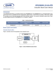
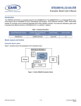
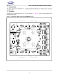
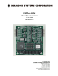
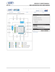
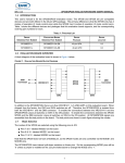
XR22804IL56-0A-EB
Evaluation Board User’s Manual
Introduction
The XR22804IL56-0A-EB is an evaluation board for the XR22804IL56-F. The XR22804IL56-F is a Hi-Speed USB 2.0 compound device with an embedded hub and 7 downstream USB functions: 10/100 Ethernet controller, 4 UARTs, multi-master
capable I2C controller and an Enhanced Dedicated GPIO Entity (EDGE) controller. This manual is intended to guide users
to operate these different functions of XR22804IL56-F on a windows 7 platform. The XR22804IL56-F shares common evaluation board with XR22802IL56-F The only difference between the XR22804IL56-F and the XR22802IL56-F is that the
XR22802IL56-F has two UART channel whereas XR22804IL56-F has four UART channels.
Table 1: Ordering Information
Device Ordering Part Number
Evaluation Board Ordering Part
Number
Device Package
Device Location
XR22804IL56-F
XR22804IL56-0A-EB
56-pin QFN
U7
XR22802IL56-F
XR22802IL56-0A-EB
56-pin QFN
U7
Board Layout and Outline
Evaluation Board outline
Figure 1 provides shows the topography of the board. For XR22802IL56-F serial port connectors for UART channel-C and
channel-D are not installed.
Ch‐B RS485 Conn
Ch‐D RS‐232
Ch‐D RS485 Conn
EDGE LEDs Ch‐B
USB port XR22804
Hi‐Speed USB‐
Ethernet
Ch A remote wake up button
Ch‐A RS485 Conn
25 MHz
EDGE LEDs Ch‐A
EDGE LEDs Ch‐C
RJ45
JACK
10/100 ETHERNET
I2C Conn.
EDGE LEDs Ch‐D
Ch‐B RS‐232
Ch‐C RS485 Conn
Ch‐A RS‐232
Ch‐C RS‐232
Figure 1: Outline XR22804 Evaluation Board
(Top View)
© 2014 Exar Corporation
1 / 16
www.exar.com\XR22804
Rev 1A
XR22804IL56-0A-EB User’s Manual
Evaluation Board Layout
Figure 2: XR22804 Evaluation board Top View
© 2014 Exar Corporation
2 / 16
www.exar.com\XR22804
Rev 1A
XR22804IL56-0A-EB User’s Manual
Software Drivers
This section provides assistance regarding installation of the drivers for the embedded hub and the downstream USB functions of the XR22804/2. The hub and the HID functions (I2C and EDGE) are supported by Windows in-box generic drivers.
Therefore no custom driver need to be installed. The Windows system should automatically load drivers for these functions.
The Ethernet and UART functions are CDC compliant functions. The XR22804/2IL56-0A-EB is shipped with an installation
CD that contains the latest Windows Xp/7 custom drivers for Ethernet and UART devices. This drivers can also be downloaded from the XR22804/2’s product web page.
Device Enumeration
When the device is first plugged into the system the embedded hub is enumerated first. It appears in the Device Manager
under the “Other devices” tab as shown in the Figure 3. In order to access the Device Manger, go to start and in the search
box enter “devmgmt.msc” and hit carriage return key on the keyboard.
Figure 3: XR22804 hub enumeration
The downstream USB functions are initially enumerated as shown in Figure 4 in Device Manager under the “Other devices”
tab before their drivers are installed.
Figure 4: Enumeration of USB downstream ports
© 2014 Exar Corporation
3 / 16
www.exar.com\XR22804
Rev 1A
XR22804IL56-0A-EB User’s Manual
Driver Installation
As mentioned previously the drivers for the embedded hub and HID functions should be installed automatically. This section
provides assistance in installing custom driver for UART and Ethernet function. The example in this manual uses
XR22804IL56-F but the steps are the same for XR22802IL56-F.
Driver Installation for Embedded HUB
Once the driver for the embedded hub is installed it will appear under “Universal Serial Bus Controller” tab as “Generic USB
Hub” as shown in Figure 5. The users may confirm the Hardware IDs of the “Generic USB Hub” devices to differentiate
between other generic hubs attached to the system.
In order to access Hardware IDs right click on “Generic USB Hub” and select “Properties”.
In Properties page go to “Details” tab, in the Property drop-down menu select “Hardware Ids”.
The Hardware ID of that device is showed under “Value” window.
For XR22804IL56-F, the value shown in this window: USB\VID_04E2&PID_0804
For XR22802IL56-F, the value shown in this window: USB\VID_04E2&PID_0802
Where 0x04E2 is the Vendor ID(VID) of Exar and 0x0804/2 is the Product ID(PID).
The downstream functions are enumerated only after the hub driver has been successfully installed.
Figure 5: XR22804IL56-F embedded hub in Device manager
© 2014 Exar Corporation
4 / 16
www.exar.com\XR22804
Rev 1A
XR22804IL56-0A-EB User’s Manual
Driver Installation for HID (I2C and EDGE) devices
Drivers for the HID devices will be installed automatically after the Hub drivers are installed and they will appear under
“Human Interface devices” tab in Device Manager. To differentiate between HID devices read the Hardware IDs. The product ID for HID-I2C is 0x1100 and for HID-EDGE is 0x1200.
Figure 6: HID devices in Device Manager
Installing Custom Driver for Ethernet Function
In the installation disc goto folder “Driver/Ethernet” and copy its contents on the hard drive. Extract all contents of the “ .zip ”
folder.
Go to device Manger and right click on “Exar USB Ethernet” under the “Other devices” tab and select “Update Driver”.
On the next wizard page select option “Browse my computer for driver software”
On the next wizard page select the option “Let me pick from a list of device drivers on my Computer” then click button “Have
Disk...” and browse to the folder where all the driver files were extracted and select the “xrusbnet.inf” file. On successful
installation of driver the device will be listed under “Network Adapters”.
© 2014 Exar Corporation
5 / 16
www.exar.com\XR22804
Rev 1A
XR22804IL56-0A-EB User’s Manual
Driver Installation for UART
The steps for installing driver for UARTs is same as steps mentioned for Ethernet drivers except the inf file for UART is
“xrusbser.inf”. The user will have to perform this task for one of the four UARTs and then re-enumerate (unplug & plug) the
device. After the drivers are installed successfully the UARTs will be listed under “Ports (COM & LPT)” in the Device Manager.
Software Application and Utilities
After successful installation of drivers, the next step in the process is to operate XR22804/2IL-0A-EB. The installation disc
contains various test applications for testing the various USB functions. It contains test application for UARTs, I2C and
EDGE functions. The user may use a web browser for evaluating the Ethernet function.
The following screen-shots and information are provided to operate the 4 different types of embedded functions for all tests
including Suspend/Resume testing. Each type of function is described separately but can/will be run simultaneously.
Ethernet 10/100 - PID 0x1300
After successful installation of Ethernet driver plug in cat-5 ethernet cable into the RJ45 ethernet jack. The device properties related to ethernet port can be modified from Device Manager. Right Click on “Exar USB Ethernet Device” instance
under “Network Adapter” and select Properties. In Properties select Advanced tab as shown below in Figure 7
Figure 7: Ethernet device Properties
In this tab the user can modify various properties related to Ethernet e.g. Flow control, Remote Wake-up modes, Speed and
Duplex modes etc. In Speed & Duplex property the users can select among different link speed configurations supported by
XR22804IL56-F in “Speed & Duplex” property. The different speed configurations are Auto Sense, 100M Full- Auto, 100M
Full- Fixed, 100M Half- Auto, 100M Half- Fixed, 10M Full- Auto, 10M Full- Fixed, 10M Half- Auto and 10M Half- Fixed. All of
this mode are explained in brief below:
© 2014 Exar Corporation
6 / 16
www.exar.com\XR22804
Rev 1A
XR22804IL56-0A-EB User’s Manual
Table 2: Speed and Duplex Settings
Property Name
Description
Auto Sense (Default)
XR22804IL56-F automatically determines the link speed through the process of Auto-Negotiation,
where XR22804IL56-F advertises itself to be 10M & 100M Full & Half capable to the link partner.
100M Full/Half -Auto
During this mode XR22804IL56-F will always advertise itself to be 100M Full/Half capable only to
the link partner.
10M Full/Half -Auto
During this mode XR22804IL56-F will always advertise itself to be 10M Full/Half capable only to the
link partner.
100M Full/Half -Fixed
During this mode XR22804IL56-F is forced to 100M Full/Half mode. There is no link negotiation with
the link partner.
10M Full/Half -Fixed
During this mode XR22804IL56-F is forced to 10M Full/Half mode. There is no link negotiation with
the link partner.
The XR22804IL56-F supports static and dynamic IPs. Follow the steps below to configure the static IP (if the static IP is
assigned):
1. Go to the Start menu
2. In the Search box, search for “View network connections” and hit carriage return
3. Right click on Local Area Connection # icon of Exar USB Ethernet shown in figure below and select properties
4. On the properties page select “Internet Protocol Version 4” and click on Properties button as shown in Figure 8
Figure 8: Local Area Connection Properties window
© 2014 Exar Corporation
7 / 16
www.exar.com\XR22804
Rev 1A
XR22804IL56-0A-EB User’s Manual
5. Configure their static IP as shown in the figure. For DHCP select the option “Obtain the IP address automatically”.
Confirm the IP settings by following the below mentioned step:
1. Go to Start menu and search for “cmd” and hit carriage return
2. In the command prompt enter “ipconfig /all”
3. It will display information for all the network adapters connected to the system. The user should look for Ethernet adapter
whose description says “Exar USB Ethernet Device # ” as shown in figure below
Figure 9: Local Area Connection adapter information
After configuring the ethernet port based on the network requirement, it will be ready to be used. Use a web browser to verify the functionality of the Ethernet port.
© 2014 Exar Corporation
8 / 16
www.exar.com\XR22804
Rev 1A
XR22804IL56-0A-EB User’s Manual
UARTs - PIDs: 0x1400 (Channel A), 0x1401 (Channel B), 0x1402 (Channel C) and 0x1403 (Channel D)
The installation disc contains the Serial_test_App.exe utility for evaluating the UARTs functions. The snapshot below shows
the UART “Serial Test App”.
8
1
11
2
3
4
9
5
10
7
6
12
13
14
15
16
17
18
19
20
Using this utility user can send and receive continuous data through UARTs. Each portion of the utility is described in Table
below:
Table 3: GUI Description
GUI Item
Name
Description
1
Connect
After selecting the appropriate UART in the list. Click “Connect’ button to open the port.
Upon successful connection the button changes to “Disconnect”. Clicking on “Disconnect” will close the port
2
Flow Control
3
Data bits
4
Parity
5
Stop bits
6
Set RS485
7
Set Custom Baud
8
User Data
9
Capture
10
Receive window
Displays data received
11
Transmit window
Displays data to be transmitted
© 2014 Exar Corporation
Selects the flow control setting: Hardware, Software or No flow control
Selects the number of data bits - 5, 6, 7, 8 & 9 per character. 5 and 6 bits are not supported by XR2280x devices
Selects among the parity types - odd, even, mark or space
Selects the length of stop bit - 1 or 2 bit time
Configures RTS pin to control a half-duplex RS485 transceiver
Sets custom baud rate. Baud rate value should be between 300bps - 15Mbps
User can enter the data to be transmitted in Transmit Window
Click this option to save the received data in to a text file
9 / 16
www.exar.com\XR22804
Rev 1A
XR22804IL56-0A-EB User’s Manual
Table 3: GUI Description
GUI Item
Name
Description
12
Baud Rate
13
Start Tx
14
Send File
15
Send U
16
Read & Write
Read button executes read command for reading register. write button executes write
button to write to the register
17
Address field
Enter register address on which read/write operation is performed
18
Application Version
19
Data field
20
Device PID
Selection among the standard baud rates
Click this button to start data transmission, the application will send a fixed pattern continuously.
Eg:
“L00 - 0123456789abcdefghijklmnopqrstuvwxyz
L01 - 0123456789abcdefghijklmnopqrstuvwxyz
L02 - 0123456789abcdefghijklmnopqrstuvwxyz...”
Once data transmission initiates successfully this button becomes “Stop” button. Click
“Stop” to stop data transmission
Select this option to send a text file
Sends ‘U’ (0x55) continuously
Displays version of the application
For Read operation: Display the read data
For Write operation: Enter data to be written
Displays Product ID(PID) of the UART
HID-I2C - PID 0x1100
The XR22804IL56-0A-EB evaluation board provides an interface (header J7) to connect I2C slave to its I2C master interface. The installation disc contains HID-I2C utility to control this HID-I2C master function. The figure shows the snapshot of
HID-I2C utility.
1
9
2
7
3
8
4
6
5
10
11
13
12
Figure 10: HID-I2C utility
© 2014 Exar Corporation
10 / 16
www.exar.com\XR22804
Rev 1A
XR22804IL56-0A-EB User’s Manual
Connect I2C slave device to the XR22804IL56-0A-EB evaluation board via 4-pin header J7. The evaluation board has 47K
pull-up installed on SDA and SCL pin refer to the schematic for more details. Run the HID-I2C test app. Push “Find
XR2280x I2C” button. Each portion of HID-I2C utility is described in table below:
Table 4: HID I2C GUI Description
GUI Item
Name
Description
1
I2C Addr
Enter the address of the Slave i2c device. The value entered should be in hexadecimal
system and right shifted by one bit.
e.g.:- If Slave address= “60” the value entered in this box will be “30”
2
Write Size
Enter in decimal the number of bytes, without including the slave address, to be sent to
slave device
3
Run
4
Read Size
5
Find XR2280x I2C
6
Bytes Readback
This window display the bytes read from the slave device. The number of bytes read is
defined by GUI item #4. This window will also display status of any operation in terms
of whether it “succeeded” or “failed”
7
Continuously Rd/Wr
Enable this box in order to perform read/write operation continuously. De-selecting the
check box will stop the operation.
8
Push this button to execute Read/Write command
Enter in decimal the number of bytes expected to be read from the slave device
Push this button to force the utility to look for XR2280x device
I2C options
These settings controls the I2C protocol
a. 10-bit Address
Check this box to enable 10-bit slave addressing mode
b. WithStart
Check this box to initiate I2C transaction with start bit. The master sends a start but followed by the address byte to select a slave and initiate a transfer.
c. WithStop
Check this box to initiate I2C transaction with stop bit. The master sends a stop bit, this
relinquishes the bus, and another master may then claim it.
d. Consecutive Read
Check this box to perform consecutive read operation
9
Bytes to Write
Enter the data string that needs to be send to slave device. If there is more than one
data byte they should be separated by space.
For eg: For write operation- In order to send data string 0x22, 0x3C, 0x4A, 0x55, 0x56
and 0x8F to slave device enter these values in box as below:
“22 3C 4A 55 56 8F”
In most slave devices the first byte is the address in slave device where the following
data should be written. For this example 0x22 is that address.
For Read Operation- Enter the Address in the slave device that needs to be accessed.
For e.g: if the address of location in slave device is 0x22 enter “22” in the box. The
value read will be shown in Bytes Readback (GUI item #6)
10
Autoincrement Values
Enable the check box to auto-increment, by 1, the data byte, specified by the offset
(GUI item #11), in Byte to Write (GUI item #9).
for e.g: if data string in “Byte to Write”= “22 3C 4A 55 56 8F” offset= 1, after every transaction data byte, in this case 0x3C, will be incremented by 1 and the remaining string
remains the same.
11
From Offset
12
Message window
All the messages related to HID-I2C is displayed in this box
13
Version
It describes the version number for the existing application
© 2014 Exar Corporation
Enter the offset location, in decimal system, of the byte in the data string in “Bytes to
Write” box
11 / 16
www.exar.com\XR22804
Rev 1A
XR22804IL56-0A-EB User’s Manual
HID-EDGE- PID 0x1200
The XR22804IL56-0A-EVB evaluation board has LEDs installed for testing EDGE pins. The LEDs are active LOW hence
they lite up when output LOW. The installation disc contains an application to control configure the EDGE pins. The user
needs to confirm the jumper settings before proceeding with this test. The figure below shows the snapshot of HID-EDGE
utility.
2
1
5
6
7
8
9
3
4
Figure 11: HID-EDGE Application
Table 5: HID I2C GUI Description
GUI Item
Name
1
Device Info
2
EDGE pin number
3
Enable EDGE
4
DIR
5
O/P TYPE
© 2014 Exar Corporation
Description
This box displays device information: Vendor ID(VID), Product ID(PID)
Element in this column references to the EDGE pin number.
E.g: E0= Edge Pin 0, E1= Edge Pin 1 etc
Check this box to configure this pin to EDGE. Uncheck this box to configure this pin to
UART
1= This pin is configures as output pin
0= This pin is configured as input pin
A drop-down menu provides three options:
1. Push-Pull: select this option to set output pin to be PUSH-PULL
2. Open-Drain: select this option to set output pin to be an open drain pin
3. Tri-State: select this option to set output pin to be a Tri-state pin
12 / 16
www.exar.com\XR22804
Rev 1A
XR22804IL56-0A-EB User’s Manual
Table 5: HID I2C GUI Description
GUI Item
Name
Description
6
SET/CLR
7
PWM Control
A drop-down menu provides three options:
1. IDLE: select this option to leave PWM output idle
2. Stp_LOW: select this option driver output LOW when PWM is idle.
3. One Shot: If output is high, run one low cycle and stop high. If output is low, run one
high cycle and stop low. Cleared to IDLE when completed.
4. RUN: select this option for PWM output to toggle HIGH-LOW.
5. Stp_HIGH: select this option driver output HIGH when PWM is idle.
8
PWM Enable
A drop-down menu provides an option to select among two PWMs. Select None to disable PWM mode
9
Status
Check this box to set the output HIGH. Uncheck this box to set the output LOW
If not configured as UART or PWM this box display state of the pin.
1= pin state is HIGH
0= pin state is LOW
For further details on any of the above functions refer to the datasheet.
Hardware Configuration
This section describes the default board settings, when shipped from the factory, and jumper setting that are required when
changing modes.
Power Configurations
When shipped from the factory, the XR22804/2 is configured for bus-powered mode and uses the 5V supplied by the USB
host.Table 6 shows the default jumper settings for power:
Table 6: Default Jumper Settings for Power
Jumper Settings
Description
J46- 1 & 2
Connects +3V3A node to +3.3V node that sources transceivers on the board.
J36- 2 & 3
Connects VBUS to the VBUS_SENSE pin through a voltage divider. VBUS_SENSE pin is ignored during bus powered mode.
J17- 1 & 2
Connect VCC_TRANS node to +3.3V node. This provides 3.3V to SP3245EEY
and SP339EER transceivers. The XR22804IL56-0A-EB evaluation board uses
the 3V3_out pin (+3.3VA node) to power the transceivers on the board.
J48-2 & 3
Connect VCC of SP3036EEN,RS485 transceiver to +3.3V node.
Pin Configurations
XR2280x IO pins supports multiple functions. They can be programmed to be UART pins or GPIO pins or EDGE pins.
When shipped from factory, IO pins of the XR22804IL56-0A-EB are programmed to be UART pins and are connected to
transceiver via jumpers. They can be connected to LED for GPIO or EDGE function testing. This selection is also made
through jumpers mentioned in tables below. LED is turned ON when pin is driven LOW.
Table 7: Default Jumper Settings for UART Channel A
Pin Name
E0/RIA#/RWKA#/GA0
© 2014 Exar Corporation
SP3245EEY(Default)
LED
Notes
J28-7 & 9
J28-9 & 11
LED is not installed. This pin
connected to a pull-up resistor
13 / 16
www.exar.com\XR22804
Rev 1A
XR22804IL56-0A-EB User’s Manual
Table 7: Default Jumper Settings for UART Channel A
Pin Name
SP3245EEY(Default)
LED
E1/CDA#/GA1
J28-8 & 10
J28-10 & 12
E2/DSRA#/GA2
J28-1 & 3
J28-3 & 5
E3/DTRA#/GA3
J28-2 & 4
J28-4 & 6
E4/CTSA#/GA4
J30-7 & 9
J30-9 & 11
E5/RTSA#/RS485A/GA5
J30-8 & 10
J30-10 & 12
E6/RxA/RWKA#
J30-1 & 3
J30-3 & 5
E7/TxA
J30-2 & 4
J30-4 & 6
Notes
Table 8: Default Jumper Settings for UART Channel B
Pin Name
SP339EER1 (Default)
LED
Notes
E8/RIB#/RWKB#/GB0
J29-7 & 9
J29-9 & 11
LED is not installed. This pin
connected to a pull-up resistor
E9/CDB#/GB1
J29-8 & 10
J29-10 & 12
E10/DSRB#/GB2
J29-1 & 3
J29-3 & 5
E11/DTRB#/GB3
J29-2 & 4
J29-4 & 6
E12/CTSB#/GB4
J37-7 & 9
J37-9 & 11
E13/RTSB#/RS485B/GB5
J37-8 & 10
J37-10 & 12
E14/RxB/RWKB#
J37-1 & 3
J37-3 & 5
E15/TxB
J37-2 & 4
J37-4 & 6
Table 9: Default Jumper Settings for UART Channel C1
Pin Name
1Note:
SP339EER1 (Default)
LED
Notes
E16/RIC#/RWKC#/GC0
J38-7 & 9
J38-9 & 11
LED is not installed. This pin connected to a pull-up resistor
E17/CDC#/GC1
J38-8 & 10
J38-10 & 12
E18/DSRC#/GC2
J38-1 & 3
J38-3 & 5
E19/DTRC#/GC3
J38-2 & 4
J38-4 & 6
E20/CTSC#/GC4
J39-7 & 9
J39-9 & 11
E21/RTSC#/RS485C/GC5
J39-8 & 10
J39-10 & 12
E22/RxC/RWKC#
J39-1 & 3
J39-3 & 5
E23/TxC
J39-2 & 4
J39-4 & 6
Not installed for XR22802
© 2014 Exar Corporation
14 / 16
www.exar.com\XR22804
Rev 1A
XR22804IL56-0A-EB User’s Manual
Table 10: Default Jumper Settings for UART Channel D1
Pin Name
1
SP339EER1 (Default)
LED
Notes
E24/RID#/RWKD#/GD0
J40-7 & 9
J40-9 & 11
LED is not installed. This pin connected to a pull-up resistor
E25/CDD#/GD1
J40-8 & 10
J40-10 & 12
E26/DSRD#/GD2
J40-1 & 3
J40-3 & 5
E27/DTRD#/GD3
J40-2 & 4
J40-4 & 6
E28/CTSD#/GD4
J41-7 & 9
J41-9 & 11
E29/RTSD#/RS485D/GD5
J41-8 & 10
J41-10 & 12
E30/RxD/RWKD#
J41-1 & 3
J41-3 & 5
E31/TxD
J41-2 & 4
J41-4 & 6
Note: Not installed for XR22802
Table 11: Remote Wake up Jumper settings
Jumper Settings
J28-9 and TP12
Description
(Not installed) This jumper connects a button switch to RI pin. This switch is
used to wake up the device from sleep
Transceiver Configurations
On XR22804/2IL56-0A-EB board there’s an SP3245EEY for RS232 communication and SP3086EEN for RS485 communication for UART channel A. It also has multi protocol transceiver, SP339EER1, for RS232/485 communication for UART
channel B,C1 and D1. When shipped from the factory the SP339EER1 transceiver are configured for RS232 communication.
The jumper setting for this mode is shown in table below.
Table 12: SP339EER1 Settings
UART Channel
Jumper number
RS-232 Mode (default)
Half-Duplex RS-485 Mode
Full-Duplex RS-485 Mode
B
J24
Jumper installed between 5&6
Jumper installed between 7&8
Jumper installed between 5&6 and 7&8
C1
J25
Jumper installed between 5&6
Jumper installed between 7&8
Jumper installed between 5&6 and 7&8
D1
J26
Jumper installed between 5&6
Jumper installed between 7&8
Jumper installed between 5&6 and 7&8
1Note:
Not installed for XR22802
Half-Duplex RS-485/422 mode
In the RS-485 half-duplex mode, the DIR1 pin of the SP339EER1 enables or disables the RS-485/422 line drivers. The
DIR1 pin can be controlled by the XR22804/2 using the RTS# output pins. The connection between RTS# and the DIR1 pin
can be made by installing a jumper between 1 & 2 of J43, J44 and J45 for UART channel B, C1 & D1 respectively. Refer to
the XR22804/2 datasheet for details for selecting and enabling the Automatic Transceiver Enable feature for the RTS# pin.
1
Note: Not installed for XR22802
© 2014 Exar Corporation
15 / 16
www.exar.com\XR22804
Rev 1A
XR22804IL56-0A-EB User’s Manual
Revision History
Revision
1A
Date
June 2014
Description
Initial release
For Further Assistance:
Email: [email protected]
Exar Technical Documentation: http://www.exar.com/techdoc/
Exar Corporation Headquarters and Sales Offices
48720 Kato Road
Tel: +1 (510) 668-7000
Fremont, CA 95438 - USA
Fax: +1 (510) 668-7001
NOTICE
EXAR Corporation reserves the right to make changes to the products contained in this publication in order to improve design, performance or reliability. EXAR Corporation
assumes no responsibility for the use of any circuits described herein, conveys no license under any patent or other right, and makes no representation that the circuits are free
of patent infringement. Charts and schedules contained herein are only for illustration purposes and may vary depending upon a user’s specific application. While the information
in this publication has been carefully checked; no responsibility, however, is assumed for inaccuracies.
EXAR Corporation does not recommend the use of any of its products in life support applications where the failure or malfunction of the product can reasonably be expected to
cause failure of the life support system or to significantly affect its safety or effectiveness. Products are not authorized for use in such applications unless EXAR Corporation
receives, in writing, assurances to its satisfaction that: (a) the risk of injury or damage has been minimized; (b) the user assumes all such risks; (c) potential liability of EXAR Corporation is adequately protected under the circumstances.
Reproduction, in part or whole, without the prior written consent of EXAR Corporation is prohibited.
© 2014 Exar Corporation
16 / 16
www.exar.com\XR22804
Rev 1A