1
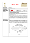
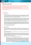
AB Safety Flash IMCA Safety Flash 05/13 April 2013 These flashes summarise key safety matters and incidents, allowing wider dissemination of lessons learnt from them. The information below has been provided in good faith by members and should be reviewed individually by recipients, who will determine its relevance to their own operations. The effectiveness of the IMCA safety flash system depends on receiving reports from members in order to pass on information and avoid repeat incidents. Please consider adding the IMCA secretariat ([email protected]) to your internal distribution list for safety alerts and/or manually submitting information on specific incidents you consider may be relevant. All information will be anonymised or sanitised, as appropriate. A number of other organisations issue safety flashes and similar documents which may be of interest to IMCA members. Where these are particularly relevant, these may be summarised or highlighted here. Links to known relevant websites are provided at www.imca-int.com/links Additional links should be submitted to [email protected] 1 Explosion Causing Fatal Injury During Maintenance of Metocean Buoy A member has reported an incident in which a crewman was fatally injured during the recovery and maintenance of a metocean buoy, after it had been in use in-sea for a period of around two years. The incident occurred after the buoy was recovered onto a service vessel for cleaning. After retrieval onto the service vessel, the buoy was cleaned, and the task of opening the instrument compartment started. This compartment also held the lead-acid battery packs of the buoy. Access was gained by removing a circular lid secured by 16 bolts. The removal of the bolts had been completed, except for the last bolt which proved to be seized. The decision was made to free this bolt using an angle grinder. Only moments after applying the grinder, an explosion took place which resulted in the lid blowing open and the instrument modules and their mounting plate being projected outwards with great force. These items struck the crewman, causing him to be fatally injured. The buoy had a discus shaped hull that could be split in two to ease transportation. A keel with counterweight was mounted under the hull to stabilise the buoy. A cylinder in the middle of the hull contains all electronic modules, the power package and the wave sensor. The different electronic modules were mounted into special splash proof compartment boxes to secure safe handling of the sensitive electronics. The buoy was equipped with a mast to support the meteorological sensors and the communication antennae. The dimensions in the diagram below are in millimetres. Line drawing of metocean buoy The immediate cause of the explosion was found, on investigation, to be sparks from the grinder igniting an explosive mixture of hydrogen and oxygen which had built up inside the compartment. The hydrogen build-up was assumed to stem from the lead-acid batteries. The lead-acid batteries contained in all metocean buoys of this sort are of the so called valve regulated type, meaning that they are sealed, except for a pressure relief valve. These batteries feature a built-in gas recombination system, and the small amounts of gas released through the valve pass through an additional catalyst before being conveyed to the outside of the buoy. This system is intended to prevent any build-up of hydrogen. The final technical investigation showed no sign of malfunction of the battery venting system. The root cause of the incident was determined to be to a combination of lack of maintenance and a failure to follow existing procedures. The investigation concluded that the following chain of events led to the hydrogen build-up, and eventually the accident. 1. Corrosion around lid sealing due to bird droppings and rain or sea spray caused the sealing to fail; 2. Water, sea salt and bird dropping (guano) ingression into the instrument compartment past the leaking lid sealing; 3. Corrosion and subsequent volume increase on details of battery rack due to ingression; 4. Increased pressure on batteries from rack, resulting in cracked battery cases; 5. Hydrogen build up due to one or more of these effects; 6. Corrosion of aluminium, accelerated by guano and sea salts dissolved in water; 7. Corrosion due to spilled battery acid from cracked batteries; 8. Gas leakage from cracked battery cases; 9. Hydrogen escapes due to leaking lid sealing and increasing temperature; 10. Grinder ignites hydrogen. The following further points were noted: The existing user documentation for these metocean buoys states that the buoys have to be purged before opening the lid to the instrument compartment. The buoys incorporate valves to allow for this procedure. In this incident this procedure was not followed; There was a warning in the manual against ignition sources; There were instructions in the manual on purging the instrument compartment; A protective cover over the instrument compartment lid and also bird spikes (to prevent birds landing on the buoy) were available and were to be fitted at that time. The following actions were taken: Improvements to warning signs and clearer instructions were developed, and also improved designs for the instrument compartment and battery rack; Development of clearer instructions, which emphasize that at all times the buoys should be treated with the assumption that they could contain an explosive gas mixture. The following precautions have now been identified: Exercise particular care with buoys that have not operated normally in the period prior to retrieval; Equalise the pressure inside the buoy to the ambient air pressure by opening the gas filling valves; Purge the interior of the buoy with air or nitrogen in order to remove any possibility of hydrogen gas, using the procedure described in the user manual; Do not allow any ignition source - including power tools - near the buoy until it is fully opened; Maintain a safe distance. Only the minimum required number of persons should be in the vicinity of the buoy until it is fully opened. Never stand in direct line of the instrument compartment lid; When flushing has been completed, proceed immediately with the opening of the lid; Leave the lid fully open for a further 10 minutes. 2 Battery Damage Caused by Charger Failure The Marine Safety Forum has published the following report regarding damage to batteries caused by the failure of the charger. The incident occurred when an engineer was carrying out planned maintenance of emergency generator. The report can be downloaded from www.marinesafetyforum.org/upload-files//safetyalerts/msf-safety-flash-13.02.pdf 3 Near Miss: Exposed Live Electrical Cable A member has reported an incident in which a live electrical cable was found exposed. The incident occurred when a vessel had returned to service after a long dry docking. During this period many parts of the vessel were worked on and modifications to the layout of the vessel were made to accommodate new equipment - in particular the fast rescue craft (FRC) and its associated launching davit were removed in order to make room for a new hyperbaric lifeboat (HLB). A member of the crew working near the new hyperbaric lifeboat noticed an electrical cable which was coiled up and stowed between a handrail and an adjacent bulkhead. The ends of the cable were not terminated but had been separated and wrapped up in electrical insulating tape. It was noted that a small amount of smoke was coming from the end of the cable and some sparking (the cable was in contact with the bulkhead). Realising that the cable was live the crewman immediately contacted the deck electrician and asked him to come and investigate. The electrician subsequently traced the cable and made it safe. The cable was identified as the supply to a halogen flood light originally intended as overboard illumination for the launch station of the vessel’s FRC. Figure: showing electrical cable and bare live wires The company’s investigation revealed the following: There had been inadequate planning and inadequate supervision of the work; The old flood lamp had been removed with no Permit To Work (PTW) or Electrical Isolation (EI) certificates in place. The underlying causes associated with the incident were: Owing to the high workload of vessel staff and the large number of jobs being undertaken simultaneously, there had been a failure of control, in that it had not been possible for ship’s officers to observe all tasks and thus ensure that vessel policies were followed; There was no evidence to suggest that any communication was made to ship yard fitters that live electrical supplies were still present within their work area; There had been inadequate planning ahead of the job being undertaken; not all power supplies in the work area were assessed or isolated; All services that were required to be isolated and removed prior to the area being handed over to the third party contractor for the installation of the HLB had been successfully completed. The requirement to remove the overboard light was not part of this original scope of work; The third-party contractor deviated from their original work scope and removed the flood lamp without the necessary PTW and EI in place; The third-party contractor did not follow the Management of Change procedure. Our member identified the following lessons: The induction to the vessel during dry dock is to be reviewed and will include additional information regarding the Management of Change procedures; The use of a single point of contact for each work area was not in place while the vessel was in dry dock. This would have allowed the third-party contractor to approach their contact and arrange the necessary PTW and EI for the additional works they required; Although this work area still had additional works to be carried out, the area was not fully surveyed once the initial works had been completed prior to handover. Further information on shipyard safety can be found in IMCA SEL 032/M 221 Guidance on safety in shipyards. 4 Finger and Hand Injuries A member has reported two incidents in which crew suffered finger or hand injuries. In the first incident, the injured person was preparing a meal in the galley. He placed a chopping board on a worktop and placed a knife on top of the chopping board. As he moved around the galley, carrying out various tasks, the knife slipped from the chopping board and landed with the blade protruding over the edge of the worktop. The injured person was unaware of this and while walking past the worktop his right hand made contact with the blade of the knife, causing a 2 cm laceration to the fleshy part of the hand, between the base of his thumb and index finger. The wound was cleaned and closed with three sutures. The injured person resumed normal duties the following day. In the second incident, the injured person was working in the Bell Hangar. At the time of the incident an external auditor was carrying out an audit of the dive system. As part of the audit the diving bell was required to be moved over the access and inspection pit. Once the bell was transferred over the access pit two axle stands were placed under the bell’s bump frame. The first axle stand was required to be adjusted for height; during this adjustment the injured persons’ right index finger got nipped in the extension mechanism. This resulted in an injury to the tip of the right index finger, which the injured person initially considered trivial and finished his work task. On examination his finger was bleeding and when reported to the medic a protective dressing was applied. Figure: 2 cm laceration caused by knife blade Figure: Illustration of where finger was pinched during adjustment of the axle stand The company’s investigation revealed that the root causes of the incident were: The company’s investigation revealed that the root causes of the incident were: The cook was attempting to undertake too many tasks at the same time whilst working alone at a busy time; Assistance from other team members was not sought during a busy period in the galley; Because they deemed the activity to be routine, persons doing the task did not communicate the need to move the dive bell and therefore there was no supervisory support in place at the time; No Task Based Risk Assessment (TBRA) or toolbox talk / pre-task assessment was carried out; The team involved in the task failed to consider conducting risk assessment as a priority before carrying out the task. Existing safety systems were not followed, i.e. knife handling policy and Task Based Risk Assessment (TBRA). The company’s investigation included a review of both incidents to identify whether there was any commonality between the root causes of both incidents. Some of the lessons learnt include: Ask for help if and when required – especially working in potentially hazardous areas (bell garage) and / or busy working areas (galley during meal service times); Appropriate supervision/supervisory support is essential in ensuring policies and safe methods of work/working tools are used; Supervisors should be informed of any hazardous activities being undertaken, before starting, to ensure adequate levels of additional personnel and / or supervision is provided to ensure HSE policies and management system requirement are applied; Safety policies and safe systems of work are put in place to assist in the protection of people, the environment, plant and equipment etc. Failure to comply with these has a detrimental effect on safety and can lead to instances of injury, damage or loss as demonstrated by the two finger injury incidents; Inadequate planning and risk assessing work tasks can result in potential hazards and control measures being overlooked. 5 High Potential Near Miss During Equipment Testing A member has reported an incident in which a heavy metal work table was dragged nearly a metre by a forklift truck. The incident occurred during troubleshooting of a heavy duty multi-strand electrical cable. Technicians connected the cable between a metal worktable vice and the rear towing / pull pin of a forklift truck, in order to allow stretching and tensioning of the cable. Once the stretched cable was tested, the tension was released and the forklift truck shut down. The cable was not disconnected from either the worktable vice or the forklift. A short time later, another employee boarded the forklift truck, started the engine and began to drive away. The cable jerked taught and pulled the metal worktable forward approximately 1m before warning shouts were recognized and the forklift was stopped. No personnel were injured and no equipment was damaged. However, the potential for personnel to have been injured and equipment to have been damaged was very high had personnel been at the work table or had the work table been pulled over. At the time of the incident there were a number of costly pieces of electronic equipment on the work bench. Figures: (Left) Work bench (Middle) electrical cable being tested (Right) Fork lift truck The company’s investigation revealed the following: There were no test procedures for the set-up and use of the forklift for stretching and tensioning the cable; There was no job safety analysis (JSA) addressing actual or potential hazards of stretching and tensioning the cable with the forklift in order to support troubleshooting of the electrical cable; The electrical cable had not been removed from either the worktable vice or the forklift once the tensioning had been completed; There was inadequate communications between employees – no communication took place between the personnel using the forklift for testing and the operator who sought to drive the forklift from the area; The operator who boarded the forklift did not inspect or walk around the vehicle before starting up and driving away; There were inadequate guards or barriers – the forklift had not been secured to prevent access (i.e., no warning signs, labels, the key had not been removed from the ignition, etc.); The testing of the cable was rushed to completion without a thorough review of all aspects of equipment, personnel and process. Further investigation revealed the following root causes: Inadequate leadership/supervision – Proper management of the overall testing process, equipment, and personnel would have prevented this near miss incident. Contributing factors to this root cause include inadequate work planning, inadequate identification and evaluation of the potential loss/hazards/risks, and inadequate or missing documentation (JSA, procedures, and/or instructions, etc.) which would have provided better control of work; Poor communication between peers – No communications took place between the operator and the using department before the operator started the forklift and drove away; Improper motivation – The failure of the operator to visually check the status of the forklift prior to use demonstrated complacency with the dangers and hazards of forklift operations. Our member took the following actions: Testing methods, especially when unique or uncommon, should be documented and a Job Safety Analysis performed to ensure all hazards and risks are identified, understood and mitigated against; Controls for equipment, personnel and process should be planned, defined and monitored for compliance by assigned, responsible personnel; Ensured that improved communication processes were established and maintained to prevent recurrence of same or similar incidents; Continued to reinforce safety protocols, practices and behaviours with all personnel to overcome complacency to work place hazards. 6 Pressure Switch Location for Fixed Fire Suppression Systems The United States Coast Guard has published the following report regarding an engine room fire in a vessel. The safety alert addresses the location of fire suppression system pressure switches aboard vessels. These critical components sense the activation of the system and then electrically secure the ventilation systems operating in the protected space. Securing the ventilation is essential in extinguishing a fire onboard a vessel. It assists in isolating the fire within the space, minimizes the introduction of additional oxygen to fuel the fire and prevents the loss of fire suppression agents from the space. Recently, a vessel with an installed fixed CO2 fire suppression system suffered extensive damage due to a fire that started in the engine room. During the fire-fighting efforts the crew reported that the engine room ventilation could not be secured. A post incident damage survey of the vessel revealed that the pressure switch used to secure the ventilation was located within the engine room. Members may wish to check the location of these switches onboard their vessels, and ensure that they are properly located. The report can be downloaded from www.uscg.mil/hq/cg5/TVNCOE/Documents/SafetyAlerts/PressureSwitch.pdf