1
Chapter5 Each component function
◆Printer port interface
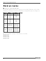
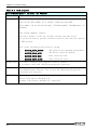
One printer port interface is provided. Resources can be either assigned or reserved
through BIOS setup (see Chapter 4).
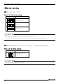
Table 5.6 Printer port and I/O address
LPT
I/O Address
Interrupt
DMA
378
IRQ7
DMA 1
1
278
IRQ5
DMA 3
IRQ7
3BC
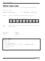
The factory default settings of the BIOS are as follows.
Mode:[SPP]、Base I/O address:[378]、Interrupt:[IRQ7]、DMA Channel:[DMA 3]
I/O address [3BC] can be selected only in Modes [Output Only] and [Bi-Directional].
DMA Channel is used only in Mode [ECP].
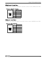
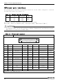
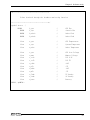
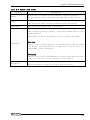
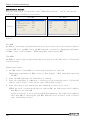
Table 5.7
Printer port connector
Connector
D-SUB 25 pin (FEMALE)
13
1
25
14
Pin No.
Signal
Function
Direction
Pin No.
Signal
Function
Direction
1
-STRB
Data effective
Output
14
-AFEED
Automatic field
Output
2
D0
Data bit0
Output
15
-ERROR
Not use
Input
3
D1
Data bit1
Output
16
-INIT
Initialization
Output
4
D2
Data bit2
Output
17
-SELECT・IN
Possible for input
Output
5
D3
Data bit3
Output
18
GND
Ground
-
6
D4
Data bit4
Output
19
GND
Ground
-
7
D5
Data bit5
Output
20
GND
Ground
-
8
D6
Data bit6
Output
21
GND
Ground
-
9
D7
Data bit7
Output
22
GND
Ground
-
10
-ACK
Possible for recieve
Input
23
GND
Ground
-
11
BUSY
Busy
Input
24
GND
Ground
-
12
PE
Non-paper
Input
25
GND
Ground
-
13
SELECT
Select state
Input
-
Fixed screw : No.4-40UNC inch screw
62
User’s Manual