1
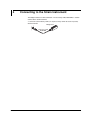
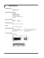
User’s
Manual
Yokogawa Electric Corporation
Model 701955 Bridge Head
(NDIS-120 Ω, Enhanced Shield)
Model 701956 Bridge Head
(NDIS-350 Ω, Enhanced Shield)
IM 701955-01E
1st Edition
Foreword
Thank you for purchasing the bridge head (701955/701956).
This User’s Manual contains useful information about the function, procedures in
connecting the gauge, and handling precautions of the bridge head. To ensure correct
use, please read this manual thoroughly before operation.
Keep the manual in a safe place for quick reference in the event a question arises.
Notes
• The contents of this manual are subject to change without prior notice as a result of
continuing improvements to the device’s performance and functions.
• Every effort has been made in the preparation of this manual to ensure the accuracy
of its contents. However, should you have any questions or find any errors, please
contact your nearest YOKOGAWA dealer as listed on the back cover of this manual.
• Copying or reproducing all or any part of the contents of this manual without
YOKOGAWA’s permission is strictly prohibited.
Revisions
• 1st Edition:
February, 2003
Disk No. DL40
1st Edition : February 2003 (YK)
All Rights Reserved, Copyright © 2003 Yokogawa Electric Corporation
IM 701955-01E
1
Checking the Contents of the Package
Unpack the box and check the contents before using the device. If the contents are not
correct or missing or if there is physical damage, contact the dealer from which you
purchased them.
Bridge Head
Check that the model name given on the name plate match that on the order. When
contacting the dealer from which you purchased the device , please quote the device
No.
MODEL
SUFFIX
MODEL
SUFFIX
NO.
NO.
Made in Japan
Made in Japan
Model
Model
Specifications
Description
700955
700956
Bridge resistance 120 Ω
Bridge resistance 350 Ω
NDIS type, enchanced shield
NDIS type, enchanced shield
No. (Device number)
When contacting the dealer from which you purchased the device, please quote this
number.
Standard Accessories
NDIS cable
(for 701955, 701956)
B8023WN
Length: 5 m
2
Attaching Plate
B9947DU
2 Binding screws
(M3 × 5 mm)
This User’s Manual
IM 701955-01E
Conventions Used in this Manual and on the Device
Symbols Used on the Device
GND terminal
The operator must refer to an explanation in the User’s Manual.
Symbols Used in this Manual
Note
IM 701955-01E
Provides important information for the proper operation of the device.
3
Contents
Foreword ........................................................................................................................................ 1
Checking the Contents of the Package .......................................................................................... 2
Conventions Used in this Manual and on the Device ..................................................................... 3
4
1
2
Construction of the Device .................................................................................................. 5
Connecting the Strain Gauge .............................................................................................. 7
3
4
Fixing the Device in Place ................................................................................................. 10
Connecting to the Strain Instrument ................................................................................. 11
5
Specifications .................................................................................................................... 12
IM 701955-01E
1
Construction of the Device
• The bridge head is a converter for inputting the amount of change of the resistance of
the strain gauge to the amplifier. Six types of connection methods (single-gauge,
single-gauge three-wire, adjacent-side two-gauge, opposed-side two-gauge,
opposed-side two-gauge three-wire, and four-gauge) are supported by setting the
switch.
• Shielded cable (B8023WN) is used.
Names of the Parts
Cable
B8023WN
Connector*
Switch
Strain gauge
connection terminal
GND
terminal
Connect to a measuring instrument.
* A connector recommended by JSNDI (The Japanese Society for Non-destructive Inspection)
Terminals and Circuit Diagram
GND terminal
(Terminal
number)
Strain gauge
conneciton
terminal
F Sense+
4
1
2
3
4
5
6
7
8
5
4
1
Attachment screws
Input–
B
3
Bridge+
3
1
6
2
8
D Input+
7
2
ON
Switch
OFF
SW 1 2 3 4 5
5
(Switch number)
GND terminal
NDIS connector
Pin assignments of the
NDIS connector (Bridge head side)
Top view
F
A
G
B
C
E
D
Pin
number
A
B
C
D
E
F
G
Signal name
Bridge+ (Bridge voltage +)
Input– (Measurement signal –)
Bridge– (Bridge voltage –)
Input+ (Measurement signal +)
Floating common
Sense+ (Sensing of the bridge voltage +)
Sense– (Sensing of the bridge voltage –)
connector shell*
* The connector shell connects the bridge head to the cable’s shielding.
IM 701955-01E
C Bridge–
G Sense–
E Floating common
Connector shell
Terminal No.
Signal name
1
Bridge+
3
Input–
4
Sense+
5
Bridge– (Sense–)
7
Input+
1 through 8 are the terminal
numbers.
1 through 5 are switch numbers.
A through G are the connector
pin numbers.
5
1 Construction of the Device
Wiring for Accessory Cable B8023WN
A wiring diagram for the accessory cable is given below. The connector shell connects
to the shielding.
B8023WN
F A
E F B
D C
A
C
D
B
F
G
E
Bridge+
Bridge–
Input+
Input–
Sense+
Sense–
Floating Common
F A
E F B
D C
A
C
D
B
F
G
E
Twist
Twist
Twist
Shell
Bridge+
Bridge–
Input+
Input–
Sense+
Sense–
Floating Common
Shell
Shield
Note
Check the shape and pin assignment of the connector before connecting it to the accessory
cable.
Circuit Diagram for Bridge Head and Measuring Instrument
The circuit diagram below shows the bridge head connected to a measuring instrument
(the DL750). Isolate the strain gauge before use.
CAUTION
Do not connect the strain gauge terminal to any items with electric potential.
Measurement instrument
(example: DL750)
Bridge Head 701955/701956
Sense+
Strain
gauge
Bridge+
Bridge+
Bridge-
R
Input+
Input+
InputR
SenseBridge-
Sense-
Case
InputSense+
R
GND
terminal
Sense+
Sense-
B8023WN
Floating
Common
The floating common of the module
is grounded within the bridge head. *1
A
C
D
B
F
G
E
Shell
Bridge+
Twist
BridgeInput+
Twist
InputSense+
Twist
SenseFloating Common
Shield
A
C
D
B
F
G
E
Shell
The shield is connected to the
The connector shell bridge head case and the
is connected to the measurement instrument case.*2
case potential of the
bridge head.*2
+
-
Module
701270
Strain(NDIS)
Bridge
Power
+
-
AD
Sense+
Sense-
All module signals
are isolated.
Floating
Common
The connector shell is connected
to the case potential of the
measurement instrument.*2 Case
*1 The GND (floating common) of the module is connected to the case potential inside the bridge head.
*2 The bridge head case, the cable shield, and the measurement instrument case are connected as measures against noise.
6
IM 701955-01E
2
Connecting the Strain Gauge
The bridge head can support six types of connection methods: single-gauge, singlegauge three-wire, adjacent-side two-gauge, opposed-side two-gauge, opposed-side twogauge three-wire, and four-gauge.
Do not connect the strain gauge terminal to any items with electric potential.
CAUTION
Do not connect the strain gauge terminal to any items with electric potential.
Use the lead wires included with the strain gauge or wires meeting the following
specifications to connect the strain gauge and the bridge head.
• Usable wire: single wire φ 0.14 to 1.5 mm2, or stranded wire 0.14 to 1.5 mm2 (AWG26
to 16)
• Normal length of bare wire : 6 mm
• The connection diagrams of several typical gauge methods are indicated on the side
of the bridge head.
2GAUGE
12 345
12 345
4GAUGE
1
2
3
4
5
6
7
8
ON
OFF
ON
OFF
12 345
1
2
3
4
5
6
7
8
1 Bridge+
2
3 Input4
5 Bridge6
7 Input+
8
ON
OFF
1GAUGE
Note
•
•
•
•
•
Isolate the strain gauge before use.
Make the wires between the strain gauge and bridge head as short as possible.
Proper measurements may not be possible in an environment where electromagnetic
interference exists.
If you are shielding the strain gauge, connect the shield wire to the floating common
terminal of the bridge head.
For the handling of the strain gauge, see the instruction manual that came with the shield
gauge.
Single-gauge Method
Strain gauge
Bridge head terminals
1
2
3
4
5
6
7
8
ON
OFF
Strain gauge
4
1
Input–
3
Sense+
Bridge+
6
2
7
Input+
8
5
Sense–
Bridge–
1 2 3 4 5
Switch setting of
the bridge head
IM 701955-01E
7
2 Connecting the Strain Gauge
Single-gauge Three-wire Method
Bridge head terminals
1
2
3
4
5
6
7
8
Strain gauge
Sense+
4
Strain gauge
Bridge+
1
6
3
2
Input–
Input+
8
ON
Sense–
Bridge–
5
OFF
7
1 2 3 4 5
Switch setting of
the bridge head
Adjacent-Side Two-gauge Method
Strain gauge
Bridge head terminals
1
Strain gauge
2
3
4
5
6
Input– 3
7
8
ON
OFF
4
1
Sense+
Bridge+
6
Input+
8
Sense–
Bridge–
5
1 2 3 4 5
7
Strain gauge
Switch setting of
the bridge head
Opposed-Side Two-gauge Method
Strain gauge
Bridge head terminals
1
2
3
4
5
6
7
8
ON
OFF
1 2 3 4 5
Strain gauge
4
1
Input– 3
Sense+
Bridge+
2
6
5
Sense–
Bridge–
7
Input+
Strain gauge
Switch setting of
the bridge head
8
IM 701955-01E
2 Connecting the Strain Gauge
Opposed-Side Two-gauge Three-wire Method
Bridge head terminals
1
2
3
4
5
6
7
8
Strain gauge
1
Input– 3
Sense+
Bridge+
2
ON
OFF
4
Strain gauge
6
7
Input+
5
Sense–
Bridge– Strain gauge
1 2 3 4 5
Switch setting of
the bridge head
Four-gauge Method
Strain gauge
Bridge head terminals
1
2
3
4
5
6
7
8
Sense+
4
Strain gauge
Bridge+
1
Strain gauge
Input– 3
ON
OFF
Input+
5
1 2 3 4 5
Switch setting of
the bridge head
IM 701955-01E
7
Strain gauge
Strain gauge
Sense–
Bridge–
9
3
Fixing the Device in Place
If necessary, you can use the accessory attaching plate, B9947-DU, to fix the bridge
head to the panel.
1.
Align the small holes on the bottom side of the bridge head to the small projections
of the attaching plate.
2.
Screw the bridge head and the attaching plate together using the accessory
binding screws (M3 × 5 mm).
Bridge head
Attaching
plate
B9947DU
Projections
Binding screws (M3 x 5mm)
10
IM 701955-01E
4
Connecting to the Strain Instrument
The bridge head uses a NDIS connector*. The accessory cable, B8023WN, is used to
connect to the strain instrument.
* A connector recommended by JSNDI (The Japanese Society for Non-destructive Inspection)
Strain instrument
Bridge head
Accessory cable
B8023WN
IM 701955-01E
11
5
Specifications
Bridge resistance
Model 701955: 120 Ω
Model 701956: 350 Ω
Applicable gauge methods
Single-gauge
Single-gauge three-wire
Adjacent-side two-gauge
Opposed-side two-gauge
Opposed-side two-gauge three-wire
Four-gauge
Operating conditions
Temperature:
Humidity:
5 to 40°C
20 to 85% RH
External dimensions
Approx. 37(W) × 97(H) × 30(D) mm
Weight
Approx. 85 g (Bridge head only)
Standard accessories
Cable (part no.: B8023WN):
Attaching plate (part no.: B9947DU):
User’s manual:
1 piece, with NDIS connector, 5 m in length
1 piece, with two M3 binding screws
1 piece, this manual
External drawings
Bridge head
97
37
30
GAUGE SELECT
OFF
SW 1 2 3 4 5
ON
1
2
3
4
5
6
7
8
BRIDGE HEAD(120 )
(ENHANCED SHIELD)
85
Attaching plate
26.9
116.5
5
12
106.5
t = 1.5
IM 701955-01E
YOKOGAWA ELECTRIC CORPORATION
Headquarters
2-9-32, Nakacho, Musashino-shi, Tokyo, 180-8750 JAPAN
Sales Headquarters
2-9-32, Nakacho, Musashino-shi, Tokyo, 180-8750 JAPAN
Phone : 81-422-52-6194
Branch Sales Offices
Nagoya, Osaka, Hiroshima, Fukuoka, Sapporo, Sendai, Ichihara, Toyoda,
Kanazawa, Takamatsu, Okayama, and Kitakyusyu.
Overseas Representative Offices / Service Centers
Beijing, Shanghai (The People's Republic of China), Jakarta (Indonesia),
Kuala Lumpur (Malaysia), Bangkok (Thailand)
YOKOGAWA CORPORATION OF AMERICA
Headquarters
2 Dart Road, Newnan, Ga. 30265-1094, U.S.A.
Phone : 1-770-253-7000
Fax : 1-770-251-0029
Branch Sales Offices / Detroit, Chicago, Los Angeles, New Jersey, Oklahoma,
Texas, San Jose, Stafford
YOKOGAWA EUROPE B. V.
Headquarters
Databankweg 20 Amersfoort 3821 AL, THE NETHERLANDS
Phone : 31-334-64-1611 Fax : 31-334-64-1610
Branch Sales Offices / Wien (Austria), Zaventem (Belgium), Ratingen
(Germany), Madrid (Spain), Runcorn (United Kingdom), Milano (Italy),
Velizy Villacoublay (France), Johannesburg (Republic of South Africa),
Budapest (Hungary), Stockholm (Sweden)
YOKOGAWA AMERICA DO SUL S.A.
Praca Acapulco, 31 - Santo Amaro. Sao Paulo/SP - BRAZIL
Phone : 55-11-5681-2400 Fax : 55-11-5681-1274
YOKOGAWA ELECTRIC ASIA PTE. LTD.
Head Office
5 Bedok South Road, 469270 SINGAPORE
Phone : 65-6241-9933 Fax : 65-6241-2606
YOKOGAWA ELECTRIC KOREA CO., LTD.
Head Office
420-5, Chongchun - 2dong, Pupyong - ku Inchon, 403-032 KOREA
Phone : 82-32-510-3107 Fax : 82-32-529-6304
YOKOGAWA AUSTRALIA PTY. LTD.
Head Office (Sydney)
Centrecourt D1, 25-27 Paul Street North, North Ryde,
N.S.W.2113, AUSTRALIA
Phone : 61-2-9805-0699 Fax : 61-2-9888-1844
YOKOGAWA BLUE STAR LTD.
Head Office
40 / 4 Lavelle Road, Bangalore 560 001, INDIA
Phone : 91-80-2271513 Fax : 91-80-2274270
Sep. '02
<Recycled Paper Used>
Printed in Japan