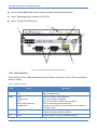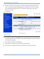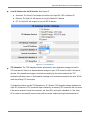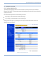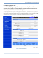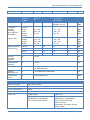
1
Viper SC IP Router For Licensed Spectrum User Manual Updated 11/18/2012 Viper SC IP Router For Licensed Spectrum ABOUT CALAMP CalAmp is a leading provider of wireless communications products that enable anytime/anywhere access to critical information, data and entertainment content. With comprehensive capabilities ranging from product design and development through volume production, CalAmp delivers cost-effective high quality solutions to a broad array of customers and end markets. CalAmp is the leading supplier of Direct Broadcast Satellite (DBS) outdoor customer premise equipment to the U.S. satellite television market. The Company also provides wireless data communication solutions for the telemetry and asset tracking markets, private wireless networks, public safety communications and critical infrastructure and process control applications. For additional information, please visit the Company’s website at www.calamp.com. Page ii Viper SC IP Router For Licensed Spectrum Table of Contents 1 2 Introduction ............................................................................................................................... 1-1 1.1 Important Notice ................................................................................................................ 1-1 1.2 Copyright Notice ................................................................................................................ 1-1 1.3 Supporting Information ...................................................................................................... 1-1 1.4 RF Exposure Compliance Requirements ........................................................................... 1-2 1.5 Product Warranty .............................................................................................................. 1-3 1.6 RMA Request .................................................................................................................... 1-3 1.7 Factory and Technical Support .......................................................................................... 1-4 1.8 Models and Availability ...................................................................................................... 1-4 1.9 Demo Kit Package Components ........................................................................................ 1-8 Product Overview ...................................................................................................................... 2-1 2.1 General Description ........................................................................................................... 2-1 2.2 Operational Characteristics ............................................................................................... 2-1 2.3 Chassis Dimensions .......................................................................................................... 2-3 2.4 Viper Connections and LED Indicators .............................................................................. 2-3 2.4.1 Front Panel Connections........................................................................................ 2-3 2.4.2 LED Indicators ....................................................................................................... 2-4 2.4.3 Ethernet LAN Port .................................................................................................. 2-5 2.4.4 SETUP and COM Ports ......................................................................................... 2-5 2.4.5 Power Connector ................................................................................................... 2-6 2.4.6 Antenna Connector ................................................................................................ 2-7 Page iii Viper SC IP Router For Licensed Spectrum 3 Network Architecture and System Planning ............................................................................ 3-1 3.1 3.2 3.3 4 Network Architecture ......................................................................................................... 3-1 3.1.1 Point-to-Point Network ........................................................................................... 3-2 3.1.2 Point-to-Multipoint Network .................................................................................... 3-2 3.1.3 Report by Exception Configuration ......................................................................... 3-3 3.1.4 Extending the Coverage Area with a Relay Point ................................................... 3-4 IP Forwarding Modes (Bridge or Router) ........................................................................... 3-5 3.2.1 Bridge Mode .......................................................................................................... 3-5 3.2.2 Router Mode .......................................................................................................... 3-8 3.2.3 Viper SC Router Generator (VRG) Program ........................................................ 3-11 3.2.4 Multispeed Networking ......................................................................................... 3-12 System Planning ............................................................................................................. 3-13 3.3.1 Site Surveys......................................................................................................... 3-13 3.3.2 Understanding RF Path Requirements................................................................. 3-14 3.3.3 Terrain and Signal Strength ................................................................................. 3-14 3.3.4 Radio Interference ............................................................................................... 3-15 3.3.5 Selecting Antenna and Lighting Arrestor Combinations........................................ 3-15 3.3.6 Selecting Antenna and Feedline .......................................................................... 3-18 3.3.7 PLC and Ladder Logic Setup ............................................................................... 3-20 3.3.8 Viper SC .............................................................................................................. 3-26 Setting Up Your Viper SC – Quick Start Guide ........................................................................ 4-1 4.1 Step 1: Install the Antenna................................................................................................. 4-1 4.2 Step 2: Measure and Connect Primary Power ................................................................... 4-1 4.3 Step 3: Connect Viper SC to Programming PC.................................................................. 4-2 Page iv Viper SC IP Router For Licensed Spectrum 5 6 4.4 Step 4: Set up PC Local Area Network (LAN) .................................................................... 4-2 4.5 Step 5: Accessing the Router’s Web Server ...................................................................... 4-8 Initial Configuration ................................................................................................................... 5-1 5.1 Welcome to the Setup Wizard ........................................................................................... 5-2 5.2 Step 1: Setup Wizard......................................................................................................... 5-3 5.3 Step 2: Setup Wizard......................................................................................................... 5-4 5.4 Step 3: Setup Wizard......................................................................................................... 5-5 5.5 Step 4: Setup Wizard......................................................................................................... 5-6 5.6 Step 5: Setup Wizard......................................................................................................... 5-7 5.6.1 Use Pre-canned Configurations ............................................................................. 5-7 5.6.2 Cloning a Viper SC ................................................................................................ 5-8 Viper SC Navigation Menu ........................................................................................................ 6-1 6.1 6.2 6.3 Home Menu ....................................................................................................................... 6-1 6.1.1 Unit Status Tab ...................................................................................................... 6-1 6.1.2 RF Status Tab........................................................................................................ 6-3 6.1.3 Basic Settings Tab ................................................................................................. 6-4 Radio Settings Menu ......................................................................................................... 6-5 6.2.1 RF Settings Tab ..................................................................................................... 6-5 6.2.2 CWID Tab (Continuous Wave Identification) .......................................................... 6-7 6.2.3 RF Tests Tab ......................................................................................................... 6-8 RF Network Settings Menu .............................................................................................. 6-10 6.3.1 RF Network Tab ................................................................................................... 6-10 6.3.2 RF Bandwidth Management Tab.......................................................................... 6-12 6.3.3 Neighbor Table Tab ............................................................................................. 6-14 Page v Viper SC IP Router For Licensed Spectrum 6.3.4 6.4 6.5 6.6 6.7 6.8 6.9 Page vi Global Settings Tab ............................................................................................. 6-18 LAN Settings Menu.......................................................................................................... 6-20 6.4.1 LAN Settings Tab ................................................................................................. 6-20 6.4.2 DHCP Tab ........................................................................................................... 6-21 6.4.3 SNTP Tab ............................................................................................................ 6-22 6.4.4 Broadcast Multicast Tab....................................................................................... 6-23 Router Menu.................................................................................................................... 6-25 6.5.1 Routing Table Tab ............................................................................................... 6-25 6.5.2 NAT Tab .............................................................................................................. 6-27 Serial Menu ..................................................................................................................... 6-29 6.6.1 Com Port and Setup Port Parameter Settings ...................................................... 6-30 6.6.2 Advanced Settings ............................................................................................... 6-31 Security Menu ................................................................................................................. 6-36 6.7.1 Password Tab ...................................................................................................... 6-36 6.7.2 AES Encryption Tab............................................................................................. 6-37 6.7.3 Radius Tab .......................................................................................................... 6-38 6.7.4 VPN Tab (Virtual Private Networking) .................................................................. 6-40 Diagnostics Menu ............................................................................................................ 6-49 6.8.1 Interface Statistics Tab......................................................................................... 6-49 6.8.2 Remote Statistics Tab .......................................................................................... 6-51 6.8.3 SNMP & Network Management Tab .................................................................... 6-52 6.8.4 Online Diagnostics Tab ........................................................................................ 6-54 6.8.5 Radio Log Tab ..................................................................................................... 6-57 Device Maintenance Menu .............................................................................................. 6-58 Viper SC IP Router For Licensed Spectrum 6.9.1 Config Control Tab ............................................................................................... 6-58 6.9.2 Package Control Tab ........................................................................................... 6-60 6.9.3 Wing Commander Tab ......................................................................................... 6-61 6.10 Setup Wizard ................................................................................................................... 6-64 7 8 9 Network Optimization ................................................................................................................ 7-1 7.1 Maximizing TCP/IP Throughput ......................................................................................... 7-1 7.2 Maximizing Throughput with a Weak RF Link .................................................................... 7-1 7.2.1 Use Router Mode with RF Acknowledgements Enabled ........................................ 7-1 7.2.2 Reduce RF Network Bit Rate ................................................................................. 7-2 7.2.3 Increase OIP and MAC Retries Limit...................................................................... 7-2 Upgrading the Firmware ........................................................................................................... 8-1 8.1 Firmware Introduction ........................................................................................................ 8-1 8.2 How is It upgraded............................................................................................................. 8-2 8.2.1 Upgrade the Modem Firmware............................................................................... 8-2 8.2.2 Upgrade the Radio Firmware ................................................................................. 8-3 APPENDIX A – Specifications................................................................................................... 9-1 10 APPENDIX B – Regulatory Certifications............................................................................... 10-1 11 APPENDIX C – Product Warranty ........................................................................................... 11-1 12 APPENDIX D – Definitions ...................................................................................................... 12-1 13 Revision History ...................................................................................................................... 13-1 Page vii Viper SC IP Router For Licensed Spectrum Table of Figures Figure 1: Chassis and Mounting Plate Dimensions ............................................................................. 2-3 Figure 2: Front Panel (Dual Port Viper 200 Shown) ............................................................................ 2-4 Figure 3: Point to Point Network ......................................................................................................... 3-2 Figure 4: Point to Multipoint Network .................................................................................................. 3-3 Figure 5: Extending Coverage Areas .................................................................................................. 3-4 Figure 6: Bridge Mode - Example 1..................................................................................................... 3-6 Figure 7: Bridge Mode - Example 2..................................................................................................... 3-7 Figure 8: Router Mode - Example 1 .................................................................................................... 3-9 Figure 9: Router Mode - Example 2 .................................................................................................. 3-11 Figure 10: Viper SC Router Generator (VRG) ................................................................................... 3-12 Figure 11: Multispeed Illustration ...................................................................................................... 3-13 Figure 12: Voltage Transient Immediately After the Gas Tube Turns On .......................................... 3-16 Figure 13: Voltage Buildup Due to Static........................................................................................... 3-17 Figure 14: Wireshark Network Analyzing Tool .................................................................................. 3-27 Figure 15: Example of Wireshark Details .......................................................................................... 3-28 Figure 16: RX/TX Antenna .................................................................................................................. 4-1 Figure 17: Setting Up the Viper SC ..................................................................................................... 4-2 Figure 18: Click Start > Control Panel ................................................................................................. 4-3 Figure 19: Click Network and Internet ................................................................................................. 4-3 Figure 20: Network and Sharing Center .............................................................................................. 4-4 Figure 21: Change Adapter Settings ................................................................................................... 4-4 Figure 22: Local Area Connection ....................................................................................................... 4-5 Figure 23: Properties Button ............................................................................................................... 4-5 Figure 24: Select Internet Protocol Version 4 (TCP/IPv4) ................................................................... 4-6 Figure 25: Define the IP Address ........................................................................................................ 4-7 Page viii Viper SC IP Router For Licensed Spectrum Figure 26: Login Authentication .......................................................................................................... 4-8 Figure 27: Unit Status Tab .................................................................................................................. 4-9 Figure 28: Navigation Menu and Display Area .................................................................................... 5-1 Figure 29: Setup Wizard Welcome Screen ......................................................................................... 5-2 Figure 30: Setup Wizard (Step 1) ........................................................................................................ 5-3 Figure 31: Enter IP Addresses (Step 2) .............................................................................................. 5-4 Figure 32: Enter Radio Channel Settings (Step 3) .............................................................................. 5-5 Figure 33: Configure the Encryption Settings (Step 4) ........................................................................ 5-6 Figure 34: Setup Wizard Complete (Step 5)........................................................................................ 5-7 Figure 35: Importing a Configuration File ............................................................................................ 5-8 Figure 36: Unit Identification and Status ............................................................................................. 6-1 Figure 37: RF Status Tab .................................................................................................................... 6-3 Figure 38: Basic Settings Tab ............................................................................................................. 6-4 Figure 39: RF Settings Tab ................................................................................................................. 6-5 Figure 40: CWID Tab .......................................................................................................................... 6-7 Figure 41: RF Tests Tab ..................................................................................................................... 6-8 Figure 42: RF Network Tab ............................................................................................................... 6-10 Figure 43: RF Bandwidth Management Tab...................................................................................... 6-12 Figure 44: Neighbor Table Tab (Bridge Mode) .................................................................................. 6-15 Figure 45: Neighbor Table (Router Mode)......................................................................................... 6-17 Figure 46: Global Settings Tab ......................................................................................................... 6-18 Figure 47: LAN Setting Tab .............................................................................................................. 6-20 Figure 48: DHCP Tab ....................................................................................................................... 6-21 Figure 49: SNTP Tab ........................................................................................................................ 6-22 Figure 50: Broadcast Multicast Tab................................................................................................... 6-23 Page ix Viper SC IP Router For Licensed Spectrum Figure 51: Routing Table Tab ........................................................................................................... 6-25 Figure 52: NAT Tab .......................................................................................................................... 6-27 Figure 53: Com Port Tab .................................................................................................................. 6-29 Figure 54: Setup Port Tab ................................................................................................................. 6-29 Figure 55: IP Gateway Service Settings ............................................................................................ 6-31 Figure 56: IP Gateway Transport ...................................................................................................... 6-32 Figure 57: Local IP Address .............................................................................................................. 6-35 Figure 58: Password Tab .................................................................................................................. 6-36 Figure 59: AES Encryption Tab......................................................................................................... 6-37 Figure 60: Radius Tab ...................................................................................................................... 6-38 Figure 61: VPN Tab .......................................................................................................................... 6-41 Figure 62: Interface Statistics Tab .................................................................................................... 6-49 Figure 63: Remote Statistics Tab ...................................................................................................... 6-51 Figure 64: SNMP Tab ....................................................................................................................... 6-53 Figure 65: SNMP Local IP Address................................................................................................... 6-53 Figure 66: Online Diagnostics Tab .................................................................................................... 6-55 Figure 67: Diagnostic Output Sample: Computer Readable and Human Readable Format .............. 6-55 Figure 68: Radio Log Tab ................................................................................................................. 6-57 Figure 69: Config Control Tab ........................................................................................................... 6-58 Figure 70: Package Control Tab ....................................................................................................... 6-60 Figure 71: Wing Commander Tab ..................................................................................................... 6-61 Figure 72: Setup Wizard Menu ......................................................................................................... 6-64 Figure 73: Identify Firmware Versions ................................................................................................. 8-1 Page x Viper SC IP Router For Licensed Spectrum List of Tables Table 1: Antenna Gain ........................................................................................................................ 1-2 Table 2: Viper SC Product Availability and Order Information ............................................................. 1-5 Table 3: Viper SC Accessories ........................................................................................................... 1-7 Table 4: LED Functionality .................................................................................................................. 2-4 Table 5: Pin-out for IEEE-802.3 RJ-45 Receptacle Contacts .............................................................. 2-5 Table 6: Pin out for DCE SETUP and COM port, 9 Contact DE 9 Connector ...................................... 2-6 Table 7: Power Connector Pin-out ...................................................................................................... 2-6 Table 8: Feedline Recommendations: Transmission Loss (per 100 feet) .......................................... 3-20 Table 9: TCP/UDP Parameter Usage ............................................................................................... 6-34 Table 10: Diagnostics Output Definitions for Computer Readable Format......................................... 6-56 Table 11: Online Diagnostics RSSI Display ...................................................................................... 6-56 Page xi Viper SC IP Router For Licensed Spectrum 1 1.1 INTRODUCTION IMPORTANT NOTICE Because of the nature of wireless communication, transmission and reception of data can never be guaranteed. Data may be delayed, corrupted (i.e., have errors), or be totally lost. Significant delays or losses of data are rare when wireless devices, such as the Viper SC, are used in a normal manner with a well-constructed network. Viper SC should not be used in situations where failure to transmit or receive data could result in damage of any kind to the user or any other party, including but not limited to personal injury, death, or loss of property. CalAmp accepts no responsibility for damages of any kind resulting from delays or errors in data transmitted or received using Viper SC, or for the failure of Viper SC to transmit or receive such data. 1.2 COPYRIGHT NOTICE © 2010 CalAmp. All rights reserved. Products offered may contain software proprietary to CalAmp. The offer to supply these products and services does not include or infer any transfer of ownership. No part of the documentation or information supplied may be divulged to any third party without the express written consent of CalAmp. CalAmp reserves the right to update its products, software, or documentation without obligation to notify any individual or entity. Product updates may result in differences between the information provided in this manual and the product shipped. 1.3 SUPPORTING INFORMATION Certain topics mentioned in this manual will require additional information. This information can be found on our website at www.calamp.com/support. Page 1-1 Viper SC IP Router For Licensed Spectrum 1.4 RF EXPOSURE COMPLIANCE REQUIREMENTS The Viper SC radio is intended for use in the Industrial Monitoring and Control and SCADA markets. The Viper SC unit must be professionally installed and must ensure a minimum separation distance between the radiating structure and any person, see Table 1. An antenna mounted on a pole or tower is the typical installation and in rare instances, a 1/2-wave whip antenna is used. Table 1: Antenna Gain Antenna Gain Min Safety Distance (cm @max power) 5 dBi 10 dBi 15 dBi VHF 123cm 219cm 389cm UHF 122cm 217cm 386cm 900 MHz 81cm 143 cm 255 cm WARNING: It is the responsibility of the user to guarantee compliance with the FCC MPE regulations when operating this device in a way other than described in this manual. The installer of this equipment must ensure the antenna is located or pointed such that it does not emit an RF field in excess of Health Canada limits for the general population. WARNING: Viper SC uses a low power radio frequency transmitter. The concentrated energy from an antenna may pose a health hazard. People should not be in front of the antenna when the transmitter is operating. Recommended safety guidelines for the human exposure to radio frequency electromagnetic energy are contained in the Canadian Safety Code 6 (available from Health Canada), the Federal Communications Commission (FCC) Bulletin 65 and the Council of the European Union’s Recommendation of 12 July 1999 on the limitation of exposure of the general public to electromagnetic fields (0 Hz to 300 GHz) (1999/519/EC). Any changes or modifications not expressly approved by the party responsible for compliance (in the country where used) could void the user's authority to operate the equipment. Very Important! Before you deploy your system you must read and understand Section 3.3.5 Selecting Antenna and Lighting Arrestor Combinations. Page 1-2 Viper SC IP Router For Licensed Spectrum 1.5 PRODUCT WARRANTY It is our guarantee that every Viper SC Radio modem will be free from physical defects in material and workmanship for ONE YEAR from the date of purchase when used within the limits set forth in APPENDIX A – Specifications and as stated in APPENDIX C – Product Warranty. If the product proves defective during the warranty period, contact our Customer Service Department at the following numbers to obtain a Return Material Authorization (RMA). Domestic - (800) 992-7774 Domestic & International – 507-833-8819 Note: Be sure to have the equipment model, serial number, along with the billing & shipping address when calling. Note: 1.6 You may also request an RMA number online at www.calamp.com. RMA REQUEST When returning a product, mark the RMA clearly on the outside of the package. Include a complete description of the problem and the name and telephone number of a contact person. RETURN REQUESTS WILL NOT BE PROCESSED WITHOUT THIS INFORMATION. Contact Customer Service CalAmp 299 Johnson Ave., Ste 110 Waseca, MN 56093 Tel 1.507.833.8819 Very Important! Be sure to have the equipment model and serial number, and billing and shipping addresses on hand when calling. For units in warranty, customers are responsible for shipping charges to CalAmp. For units returned out of warranty, customers are responsible for all shipping charges. Return shipping instructions are the responsibility of the customer. Page 1-3 Viper SC IP Router For Licensed Spectrum 1.7 FACTORY AND TECHNICAL SUPPORT Hours: Address: Monday-Friday 7:30-4:30 CST CalAmp Tel 507.833.8819 299 Johnson Ave., Ste 110, Fax 507.833.6758 Waseca, MN 56093 Email [email protected] 1.8 MODELS AND AVAILABILITY The Viper SC is available in various models, see Table 2. Each is available with a range of features, kits, and accessories. Refer to for Page 1-4 Viper SC IP Router For Licensed Spectrum Table 3 for Viper SC accessories. Table 2: Viper SC Product Availability and Order Information Model Number Frequency Range Description 140-5018-502 136 - 174 MHz Viper SC-100 140-5018-503 136 - 174 MHz Viper SC-100 (Dual Port) 250-5018-500 136 - 174 MHz Viper SC-100 Demo Kit 140-5118-502 136 - 174 MHz Viper SC-100 Standard Base Station 140-5318-502 136 - 174 MHz Viper SC-100 Redundant Base Station 140-5028-502 215 - 240 MHz Viper SC-200 140-5028-503 215 - 240 MHz Viper SC-200 Dual Port 250-5028-502 215 - 240 MHz Viper SC-200 Demo Kit 140-5128-502 215 - 240 MHz Viper SC-200 Standard Base Station 140-5328-502 215 - 240 MHz Viper SC-200 Redundant Base Station 140-5048-302 406.1 - 470 MHz Viper SC-400 (Range 3) 140-5048-303 406.1 - 470 MHz Viper SC-400 (Range 3) Dual Port 250-5048-300 406.1 - 470 MHz Viper SC-400 (Range 3) Demo Kit 140-5148-302 406.1 - 470 MHz Viper SC-400 (Range 3) Standard Base Station 140-5348-302 406.1 - 470 MHz Viper SC-400 (Range 3) Redundant Base Station 140-5048-502 450 - 512 MHz Viper SC-400 (Range 5) 140-5048-503 450 - 512 MHz Viper SC-400 (Range 5) Dual Port 140-5048-600 450 - 512 MHz Viper SC-400 (Range 5), AS/NZ Compliant 250-5048-500 450 - 512 MHz Viper SC-400 (Range 5) Demo Kit 140-5148-502 450 - 512 MHz Viper SC-400 (Range 5) Standard Base Station 140-5348-502 450 - 512 MHz Viper SC-400 (Range 5) Redundant Base Station 140-5098-502 928 - 960 MHz Viper SC-900 140-5098-503 928 - 960 MHz Viper SC-900 Dual Port 250-5098-500 928 - 960 MHz Viper SC-900 Demo Kit 140-5198-502 928 - 960 MHz Viper SC-900 Standard Base Station 140-5398-502 928 - 960 MHz Viper SC-900 Redundant Base Station EN 300 113 Compliant, AS/NZ Compliant Versions 140-5018-600 142 - 174 MHz Viper SC-100 EN 300 113 Compliant, AS/NZ Compliant 140-5018-601 142 - 174 MHz Viper SC-100 Dual Port Page 1-5 Viper SC IP Router For Licensed Spectrum Model Number Frequency Range Description EN 300 113 Compliant, AS/NZ Compliant 140-5118-600 142 - 174 MHz Viper SC-100 Standard Base Station EN 300 113 Compliant, AS/NZ Compliant 140-5318-600 142 - 174 MHz Viper SC-100 Redundant Base Station EN 300 113 Compliant, AS/NZ Compliant 140-5048-400 406.1 - 470 MHz Viper SC-400 (Range 3) EN 300 113 Compliant, AS/NZ Compliant 140-5048-401 406.1 - 470 MHz Viper SC-400 (Range 3) Dual Port EN 300 113 Compliant, AS/NZ Compliant 140-5148-400 406.1 - 470 MHz Viper SC-400 (Range 3) Standard Base Station EN 300 113 Compliant, AS/NZ Compliant 140-5348-400 406.1 - 470 MHz Viper SC-400 (Range 3) Redundant Base Station EN 300 113 Compliant, AS/NZ Compliant 140-5048-600 450 - 512 MHz Viper SC-400 (Range 5) EN 300 113 Compliant, AS/NZ Compliant 140-5048-601 450 - 512 MHz Viper SC-400 (Range 5) Dual Port EN 300 113 Compliant, AS/NZ Compliant 140-5148-600 450 - 512 MHz Viper SC-400 (Range 5) Standard Base Station EN 300 113 Compliant, AS/NZ Compliant 140-5348-600 450 - 512 MHz Viper SC-400 (Range 5) Redundant Base Station EN 300 113 Compliant, AS/NZ Compliant Page 1-6 Viper SC IP Router For Licensed Spectrum Table 3: Viper SC Accessories Model Number Description 250-0200-100 Barrel Connector, N type, Female 250-0697-103 TNC-Male to N-Male 18” 250-0697-104 TNC-Male to N-Male 48” 250-0697-105 TNC-Male to N-Male 72” 250-0697-106 TNC-Male to N-Female 18” 897-5008-010 Viper SC Power Cable 150-5008-001 Factory Installed Viper SC Fan Kit 150-5008-002 Field Installed Viper SC Fan Kit Page 1-7 Viper SC IP Router For Licensed Spectrum 1.9 DEMO KIT PACKAGE COMPONENTS Page 1-8 Viper SC IP Router For Licensed Spectrum 2 PRODUCT OVERVIEW The Viper SC provides any IP-enabled device with connectivity to transmit data. This DSP-based radio was designed for industrial applications utilizing 136-174 MHz, 215-240 MHz VHF, 406.1-512 MHz UHF, 928-960 MHz, 142-174 MHz, 406.1-470 MHz, and 450-512 MHz frequencies. Operational as a narrowband IP Modem or Router, Viper SC is optimized for use in SmartGrid, Distribution Automation, and SCADA applications. SCADA applications are defined as those with one or more centralized control sites used to monitor and control remote field devices over wide areas. For example, a regional utility may monitor and control networks over an entire metropolitan area. Industry sectors with SCADA systems include energy utilities, water and wastewater utilities, and environmental groups. 2.1 GENERAL DESCRIPTION This device has been designed to replace wire lines. The device’s Ethernet and RS-232 serial ports allow direct connection to Programmable Logic Controllers (PLCs) or Remote Terminal Units (RTUs). The Viper supports serial and Ethernet/IP Remote Terminal Units (RTU) and programmable logic controllers (PLC). It is standard IEEE 802.3 compliant. Viper supports any protocol running over IPv4 (including ICMP, IPinIP, IPSec, RSVP, TCP and UDP protocols). It provides MAC layer bridging and HTTP, ARP, and static routing packet forwarding. 2.2 OPERATIONAL CHARACTERISTICS Viper has the following operational characteristics: Frequency range of 136-174 MHz, 215-240 MHz, 406-512 MHz, or 928-960 MHz 142-174 MHz, 406.1-470 MHz, and 450-512 MHz frequency ranges certified for European Union (ETSI EN300 113) and for Australia/New Zealand (ACMA AS/NZS 4925-2004 (Spectrum Impact Assessment) User-selectable data rates – up to 128 kbps @ 50 kHz Wide input power range of 10 - 30 volts DC Built-in transceiver adjustable from 1 - 10 watts (8 watts max for 900MHz) Page 2-1 Viper SC IP Router For Licensed Spectrum Used as an access point or an end point with each configurable in the following: (a) Bridge mode for quick setup of units on same network (b) Router mode for advanced networks Embedded web server to access status and/or setup information Remote access for over-the-air system firmware upgrades Advanced AES 128-bit and 256-bit (via VPN Tunnels) data encryption and security designed to meet FIPS 140-2 requirements Superior data compression (zlib compression algorithm applies to Serial and IP connections) Native UDP and TCP/IP support Online and Offline Diagnostics Supports up to 32 different frequency channel pairs Rugged die-cast aluminum and steel case UL Certified when powered by a listed Class 2 source Page 2-2 Viper SC IP Router For Licensed Spectrum 2.3 CHASSIS DIMENSIONS Figure 1 shows the dimensions of the chassis and mounting plate. Figure 1: Chassis and Mounting Plate Dimensions NOTE: The equipment is intended for installation only in a RESTRICTED ACCESS LOCATION per EN60950-1:2006. 2.4 VIPER CONNECTIONS AND LED INDICATORS Viper consists of two logic printed circuit boards (PCBs), one that includes the modem circuitry and the other the radio module. Both are installed in a cast aluminum case. The unit is not hermetically sealed and should be mounted in a suitable enclosure when dust, moisture, and/or a corrosive atmosphere are anticipated. 2.4.1 Front Panel Connections The front panel has the following connections, see Figure 2. Item 1: RJ-45 LAN 10 BaseT Ethernet connection with Auto-MDIX Item 2: 50 ohm TNC female antenna connector Page 2-3 Viper SC IP Router For Licensed Spectrum Item 3: 50 ohm SMA female receive antenna connector (Dual-Port models only) Item 4: Right-angle power connector (10-30 VDC) Item 5: Two DE-9F RS-232 ports 3 6 4 2 1 5 Figure 2: Front Panel (Dual Port Viper 200 Shown) 2.4.2 LED Indicators There are five Tri-Color LEDs located at the top of the Viper, see Figure 2, Item 6. Their functionality is shown in Table 4. Table 4: LED Functionality LED Color Definition Power Green Red Viper SC ready, normal operations Viper SC hardware fault Status Green Blinking Green Red Amber (Solid or Blinking) Blinking Amber Viper SC no faults, normal operations Viper SC scanning for neighbors Viper SC has a fault condition, check unit status Viper SC detects high background noise Blinking one second On and one Off indicates an On channel interference issue. ACT Blinking Green Off Ethernet activity detected on PHY link (RJ45) No Ethernet activity on PHY link (RJ45) Lnk Green Physical Ethernet connection established (RJ45) Page 2-4 Viper SC IP Router For Licensed Spectrum Rx/Tx Off No physical Ethernet connection (RJ45) Green Red Receiving data Transmitting data 2.4.3 Ethernet LAN Port The Ethernet LAN port is an RJ-45 receptacle with a 10 BaseT Ethernet connection and Auto-MDIX. The Viper does not auto-negotiate the speed, it is a fixed 10 Mbps. Refer to Table 5 for pin out descriptions. Table 5: Pin-out for IEEE-802.3 RJ-45 Receptacle Contacts Contact 10 Base-T Signal 1 TXP(1) 2 TXN(1) 3 RXP(1) 4 SPARE 5 SPARE 6 RXN(1) 7 SPARE 8 SPARE SHELL Shield (1) The name shows the default function. Given the Auto-MDIX capability of the Ethernet transceiver, TX and RX function could be swapped. 2.4.4 SETUP and COM Ports The SETUP and COM serial connections are DE-9F RS232 ports. Refer to Table 6 for pin out descriptions. Several serial port considerations are: Viper SETUP and COM ports are Data Communication Equipment (DCE) devices. In general, equipment connected to the Viper SC’s serial ports is Data Terminal Equipment (DTE) and a straight-through cable is recommended. Note: A typical PC com port is a DTE device and would require a straight through cable to connect to the Viper’s com ports. If a DCE device is connected to the Viper serial ports, a null modem cable/adapter is required. Page 2-5 Viper SC IP Router For Licensed Spectrum Table 6: Pin out for DCE SETUP and COM port, 9 Contact DE 9 Connector Contact EIA-232F Function Signal Direction 1 DCD(1) DTE ← DCE 2 RXD DTE ← DCE 3 TXD DTE → DCE 4 DTR DTE → DCE 5 GND DTE --- DCE 6 DSR(2) DTE ← DCE 7 RTS(1) DTE → DCE 8 CTS(1) DTE ← DCE 9 RING (3) DTE --- DCE (1) Programmable (2) Always asserted (3) For future use 2.4.5 Power Connector The Viper is supplied with a right-angle power connector (10-30 VDC). The image in Table 7 shows the pin out connections for the power connector. Table 7: Power Connector Pin-out Contact (Left to Right) Color 4 Description Fan Power Output (5V) 3 Black Ground 2 Red Positive (10-30) VDC White Enable to Power Management Power - Viper is awake. No power - Viper is asleep. 1 Note: 4 3 2 1 The White Enable line must be tied to the red positive lead of the connector for the Viper SC to function. WARNING – EXPLOSION HAZARD. Do not disconnect unless power has been removed or the area is known to be non-hazardous. Page 2-6 Viper SC IP Router For Licensed Spectrum 2.4.6 Antenna Connector Very Important! Before you deploy your system you must read and understand Section 3.3.5. The standard Viper models have a 50 ohm TNC female antenna connector. This connection functions for both transmit and receive. Dual-Port models, as shown in Figure 2, feature a 50 ohm TNC female antenna connector functioning for transmit (only) and a 50 ohm SMA female antenna connector functioning for receive (only). The separate receive antenna connector is ideal for applications that require additional receive filtering, external PA(s) and other options. Warning: The transmit antenna port must not be connected directly to the receive antenna port of the Dual-Port Viper SC. Excessive power into the receive antenna port will damage the radio. Input power to the receiver should not exceed 17 dBm (50mW). To reduce potential interference, the antenna type and its gain should be chosen to ensure the effective isotropic radiated power (EIRP) is not more than required for successful communication. WARNING – EXPLOSION HAZARD: Do not disconnect unless power has been removed or the area is known to be non-hazardous. WARNING -EXPLOSION HAZARD: Substitution of components may impair suitability for Class I, Division 2. The unit must be powered with a Listed Class 2 or LPS power supply or equivalent. Note: The antenna connector is for connection to antennas housed inside of a suitable enclosure. Page 2-7 Viper SC IP Router For Licensed Spectrum 3 NETWORK ARCHITECTURE AND SYSTEM PLANNING This section discusses network architecture, basic network types, interfacing modems and DTE, data protocols for efficient channel operation, as well as providing tips for selecting an appropriate site, antenna selection, and reducing the chance of harmful interference. 3.1 NETWORK ARCHITECTURE In a radio system, only one radio should transmit at a time. If two radios transmit at the same time to another radio, RF collisions occur. Collisions will slow data traffic and may corrupt data. Most SCADA networks have a device that is configured to be the ‘polling master’. It is the responsibility of this polling master to control RF traffic so RF collisions do not occur. The Viper has RF collision avoidance technology (checks the air wave for a carrier before transmitting) and Ethernet CSMA (Carrier Sense Multiple Access). CSMA is an Ethernet collision avoidance mechanism technology built into to all Ethernet connections. However, these technologies must still be supplemented by the HMI/PLC polling master to optimize RF data traffic. Some HMI/PLC Ethernet applications may depend solely on Ethernet CSMA to control the flow of messages to avoid RF collisions in a Viper data network. This may flood the network with multiple polling messages, making it difficult for the RTUs to acquire the airwave to transmit their reply messages. This will cause the RTUs to compete for airtime and a dominant RTU may be created. While the dominant RTU/radio is transmitting, the other RTUs will send their reply messages to their connected Viper SC. Viper SCs will buffer reply messages because the dominant RTU/radio is transmitting (carrier is present). A Viper SC will buffer (while a carrier is present) a reply message until it can capture the airwave (carrier absent) to transmit. There could be five or six RTU/radios in a small system (or 10 or 20 in a large system), which could be trying to capture the airwaves to transmit. The RTUs will not respond in the order they were polled but will respond when they are ready and have captured the airwaves. The dominant RTU is created because it happens to reply at just the right time and be in the right order in the polling sequence. A common method for a polling master to manage RF traffic is for the HMI/PLC polling master to poll one remote at a time. The next polling message is not sent until the current message has been completed (“Done”) or has timed out. This prevents more than one outstanding polling message. Ladder logic programs typically refer to these parameters as the message “Done” and “Error” bits. The “Done” and “Error” bits parameter values can be adjusted for longer timeout values, if required. Page 3-1 Viper SC IP Router For Licensed Spectrum Because the Viper SC has the ability to use two completely different and separate SCADA polling protocols, it is important to have interaction between the two protocols. The Viper SC can send out an Ethernet TCP/IP polling message and also an RS232 polling message, which may or may not be generated by the same HMI/PLC. CalAmp recommends the user program the polling sequence in each protocol with logic that interacts with the other’s protocol “Done” and “Error” bits. The Ethernet polling protocol would not be allowed to send a message until the current Ethernet message is either “Done” or “Error” and the previous RS232 message are either “Done” or “Error” bits are set. The RS232 polling protocol would also have a similar logic. 3.1.1 Point-to-Point Network The point-to-point network, shown in Figure 3, is the most simple of all networks, and may be used for connecting a pair of PC's, a host computer and a terminal, a SCADA polling master and one remote, or a wide variety of other networking applications. Figure 3: Point to Point Network 3.1.2 Point-to-Multipoint Network The Point-to-Multipoint network, shown in Figure 4, is a common network type used in SCADA and other polling systems. The Master Polling station communicates with any number of remotes and controls the network by issuing polls and waiting for remote responses. Individual PLC/RTU remotes manage addressing and respond when their individual addresses are queried. PLC/RTU unit addresses are maintained in a scanning list stored in the host program or master terminal device at the SCADA host site. Communications equipment is transparent and does not interact with specific remotes; all data is coupled to the host on a single data line (such a network is commonly used with synchronous radio modems and asynchronous radio modems). Page 3-2 Viper SC IP Router For Licensed Spectrum Figure 4: Point to Multipoint Network 3.1.3 Report by Exception Configuration In a true Report by Exception configuration, the remotes send data to the master only when an event or exception has occurred in the remote. However, most Report by Exception systems have a master/remote polling component. The master polls the remotes once every hour or half-hour to ensure there is still a valid communication path. In a Report by Exception configuration, there will not be a master controlling RF traffic and RF collisions will often occur. The Viper SC has several collision avoidance features to help minimize collisions. The Viper SC is a “polite radio”. This means the Viper SC will check the RF traffic on the receive channel before transmitting. If there is no RF traffic present (no carrier present) it will transmit. If there is RF traffic (carrier present) the Viper SC will buffer the data. The Viper SC transmits the buffered data when there is no RF traffic present. Page 3-3 Viper SC IP Router For Licensed Spectrum 3.1.4 Extending the Coverage Area with a Relay Point A Viper SC can be configured as a Relay Point, as shown in Figure 5. Relay Points provide store and forward repeating of necessary information from one coverage area to the next. In Bridge mode all traffic is forwarded. In Router mode, only Broadcast Packets and address specific packets are forwarded. There may be multiple Relay Points to extend coverage over several hops. Note: Multiple relay points in a single network may slow the flow of data traffic. Serial data is always sent out as a broadcast message. A broadcast message cannot take advantage of IP routing mode so it must use Relay Points to move from one RF coverage area to another. However the Viper SC might be able to be configured in a manner that may be able to take advantage of the router mode feature and also router mode collisions avoidance features as well. Please refer to the Support Bulletins on CalAmp’s website for additional information. To configure your Viper SC as a Relay point, refer to the Neighbor Table in Section 6.3.3. Figure 5: Extending Coverage Areas Page 3-4 Viper SC IP Router For Licensed Spectrum 3.2 IP FORWARDING MODES (BRIDGE OR ROUTER) All Ethernet capable devices, or hosts, have at least one IP address and a subnet mask assigned to it. The IP address identifies a specific device and the subnet mask tells the device which other IP addresses it can directly communicate with. When any host needs to communicate, with another device that is not within the same local area network, it will first send the data packet to the gateway or router. The gateway or router then forwards the packet to the desired location. Often times a packet will pass through several gateways or routers to get to its final destination. There are two different modes of operation: Bridge Mode - Bridge mode is for quick setup of units on the same network. Router Mode - Router mode is for advanced networks. 3.2.1 Bridge Mode Bridge mode is the simplest configuration for all Viper SC networks. The Viper SC may be configured for bridge mode only when all devices are located on the same Local Area Network (LAN). Thus, all units in the network can communicate directly with all other units in the network. Each Viper SC has only one IP address assigned to it and the subnet mask is the same for every Viper SC in the network. Bridge mode does not require each Viper SC to have a unique IP address, but it is highly recommended and necessary for remote programming of the radio. Every Viper SC ships from the factory with the default Ethernet IP address of 192.168.205.1 and a subnet mask of 255.255.255.0. The default subnet of the Viper SC consists of addresses from 192.168.205.0 to 192.168.205.255. The first and last IP address of each subnet is reserved, no matter what the subnet size is. The first IP address in the subnet is the Network ID. The last IP address in the subnet is the Broadcast Address. 3.2.1.1 Bridge Mode - Example 1 This example illustrates a sample Viper SC network. The subnet consists of IP addresses ranging from 192.168.205.0 to 192.168.205.255. The subnet mask is 255.255.255.0. This is sometimes written in shorthand notation as: 192.168.205.1/24 since the subnet mask 255.255.255.0 contains 24 ones then 8 zeros when it is converted to binary. The first address 192.168.205.0 is reserved for the Network ID. The last address 192.168.205.255 is reserved for the broadcast address. Page 3-5 Viper SC IP Router For Licensed Spectrum There are 254 valid IP addresses that may be assigned to hosts on the network. Ethernet Subnet Mask 255.255.255.0 Viper SC #1 192.168.205.1/24 Network ID 192.168.205.0 PLC/RTU # 192.168.205.10/24 Broadcast Address 192.168.205.255 Computer #1 192.168.205.100/24 Viper SC #2 192.168.205.2/24 Viper SC #3 192.168.205.3/24 PLC/RTU #2 192.168.205.20/24 PLC/RTU #3 Viper SC #4 192.168.205.4/24 Viper SC #100 192.168.205.253/24 PLC/RTU #4 192.168.205.40/24 PLC/RTU #100: 192.168.205.254/ 24 192.168.205.30/24 Figure 6: Bridge Mode - Example 1 3.2.1.2 Bridge Mode - Example 2 The subnet for this Viper SC network is comprised of devices with IP addresses ranging from 172.20.0.0 to 172.20.255.255. The subnet mask is 255.255.0.0. The shorthand notation is: 172.20.0.1/16 since the subnet mask 255.255.0.0 contains 16 ones then 16 zeros when it is converted to binary. The first address 172.20.0.0 is reserved for the Network ID. The last address 172.20.255.255 is reserved for the broadcast address. Page 3-6 Viper SC IP Router For Licensed Spectrum There are 65534 valid IP addresses available to be assigned to hosts on the network. Ethernet Subnet Mask 255.255.0.0 Viper SC #1: 172.20.0.1/16 Network ID 172.20.0.0 Viper SC #2: 172.20.0.2/16 Broadcast Address 172.20.255.255 Viper SC #3: 172.20.0.3/16 Viper SC #105: 172.20.0.105/16 PLC/RTU #1: 172.20.255.1/16 Computer #1: 172.20.138.1/16 PLC/RTU #2: 172.20.255.2/16 Computer #500: 172.20.255.254/16 PLC/RTU #3: 172.20.255. 3/16 PLC/RTU #250: 172.20.255.250/16 Figure 7: Bridge Mode - Example 2 Note: For additional assistance or recommendations on configuring the unit for “Bridge Mode” refer to CalAmp’s Service Bulletins located on our website. Page 3-7 Viper SC IP Router For Licensed Spectrum 3.2.2 Router Mode Router mode allows greater network configuration flexibility. It allows the use of a variety of protocols, and also adds RF diagnostics capability to Viper SC networks. Diagnostics can be retrieved through the Ethernet port of the Viper SC. For more information on Viper SC RF Diagnostics, refer to Section 6.8. Router mode requires the setup of Ethernet IP and Serial IP addresses and is recommended only for users who have IT/Network support readily available to them and/or the authorization required to make changes in to the network. In Router mode, each Viper SC uses these two IP addresses: The Ethernet IP Address The RF IP Address Every Viper SC is factory configured with a default Ethernet IP Address 192.168.205.1 and a unique RF IP address. This RF IP address will have the form 10.x.y.z where x, y, and z is based on the last 6 digits of the unit’s Ethernet MAC address. The default network is 10.0.0.0/8. In Router mode, each Viper SC must have its Ethernet IP Address on a unique network and all Viper SCs must have their RF IP addresses on the same network. For consistent and reliable communication, the RF network addresses should not overlap or contain any of the IP Addresses in the Ethernet network. The reader can find basic Router and Subnet Tutorials on the CalAmp website in the Support Bulletin Section. These Support Bulletins are a simple explanation of subnet masks and how routers forward IP packets to other devices. Router Mode – Example 1 3.2.2.1 In the example, shown in Figure 8, each Viper SC has an Ethernet IP address on a unique network. For Viper SCs #1, #2, and #3, each network, connected to their local Ethernet ports, has 254 valid IP addresses that may be assigned to other hosts. The network connected to Viper SC #4’s local Ethernet port has 65534 valid IP addresses. Note 1: All Viper SCs’ RF IP addresses are on the same network. Because they are using the 10.0.0.0/8 network, all Viper SCs may use the default RF IP address programmed by the factory. Note 2: All the Viper SC Ethernet IP addresses are on different networks. Page 3-8 Viper SC IP Router For Licensed Spectrum Note 3: Computers, PLCs, RTUs, or other Ethernet capable devices can be connected to each Viper SC’s local Ethernet interface. That device must be set with an IP address on the same network as the Ethernet interface of the Viper SC it is connected with. Ethernet Subnet Mask: Varies from Viper SC to Viper SC. RF Subnet Mask for all units: 255.0.0.0 HMI/PLC/RTU Default Gateway points to the Viper SC that the HMI/PLC/RTU is connected to. Viper SC 1: Ethernet IP Address: 192.168.205.1/24 RF IP Address: 10.11.12.25/8 PLC 1: 192.168.205.2/24, Default Gateway: 192.168.205.1 Computer/HMI 1: 192.168.205.3/24, Default Gateway: 192.168.205.1 Viper SC 2: Ethernet IP Address: 192.168.206.1/24 RF IP Address: 10.9.7.251 / 8 PLC #2: 192.168.206.2 / 24, Default Gateway: 192.168.206.1 Viper SC #3: Eth IP Address: 192.168.207.1/24 PLC #3: 192.168.207.2/24, Default Gateway: 192.168.207.1 Computer #3: 192.168.207.3/24, Default Gateway: 192.168.207.1 Viper SC #4: Eth IP Address: 172.21.51.105/16 PLC #4: 172.21.51.106/16, Default Gateway: 172.21.51.105 RF IP Address: 10.8.0.52 / 8 RF IP Address: 10.0.1.11/8 Figure 8: Router Mode - Example 1 Page 3-9 Viper SC IP Router For Licensed Spectrum 3.2.2.2 Router Mode - Example 2 Each Viper SC has an Ethernet IP address on a unique network. Solarwind’s™ Subnet Calculator can be used to help you generate the subnets as shown in Figure 9. The Subnet calculator creates a range of hosts IP addresses that can be used. The Solarwind’s calculator can be downloaded from Solarwind’s website and a Subnet tutorial can be found on CalAmp’s Support Bulletin website. In the example shown in Figure 9, each network connected to the Viper SC’s local Ethernet port has 14 valid IP addresses that may be used for the Viper SC, PLCs, RTUs, computers, or other Ethernet equipment that may be connected. The subnet mask of the RF IP addresses has been changed to ensure that the RF IP network does not overlap any of the Ethernet networks. In this scenario, the RF IP addresses must be manually programmed to ensure that every Viper SC has an RF IP address in the network and that no RF IP address is used twice. Ethernet Subnet Mask for all units: 255.255.255.240 RF Subnet Mask for all units: 255.255.0.0 Viper SC #1 Eth IP Address: 10.200.1.1 / 28 RF IP Address: 10.0.0.1 / 16 Viper SC #2 Eth IP Address: 10.200.1.17 / 28 RF IP Address: 10.0.0.2 / 16 Viper SC #3 Eth IP Address: 10.200.1.33 / 28 RF IP Address: 10.0.0.3 / 16 Viper SC #4 Eth IP Address: 10.200.1.49 / 28 RF IP Address: 10.0.0.4 / 16 Viper SC #177 Eth IP Address: 10.200.12.1 / 28 RF IP Address: 10.0.0.177 / 16 Viper SC #178 Eth IP Address: 10.200.12.17 / 28 RF IP Address: 10.0.0.178 / 16 Page 3-10 Viper SC IP Router For Licensed Spectrum Figure 9: Router Mode - Example 2 3.2.3 Viper SC Router Generator (VRG) Program We have developed a Viper SC Route Generator (VRG) application that assists you in generating the Viper SC’s neighbor/router tables and also generates the configuration files for all the radios in your project within minutes, see Figure 10. You should try to choose an IP addressing scheme so that the master Viper SC’s IP address is always first in a sequence and then the remote’s IP addresses to follow in that sequence. Please visit CalAmp’s website and download the VRG application and VRG Support Bulletins. The Support Bulletins will step you through using the VRG application. (Currently not on website) Page 3-11 Viper SC IP Router For Licensed Spectrum Figure 10: Viper SC Router Generator (VRG) 3.2.4 Multispeed Networking When using a Viper SC with a Viper SC multispeed base station, see Figure 11, the user can configure the network for multispeed operation. With the Base enabled as a ‘rate-controller’, the remote device becomes a ‘rate follower’. The rate-controller can be configured to talk at different over-the-air data rates for each remote Viper SC. This allows the user to uniquely control the data rate for each RF link in the system from the Base Station web pages. The user can program RF links with a strong signal strength to communicate at fast data rates and RF links with low signal strength can be programmed to communicate at more robust, slower data rates. Even if data rates vary from Viper SC to Viper SC, every Viper SC in the network must be programmed with the same bandwidth. Page 3-12 Viper SC IP Router For Licensed Spectrum Figure 11: Multispeed Illustration 3.3 SYSTEM PLANNING 3.3.1 Site Surveys A Site Survey is a propagation study of the RF path between two points or between one point and multiple points. Signal propagation may be affected by attenuation from obstructions such as terrain, foliage, or buildings in the transmission path. A Site Survey is recommended for most projects to determine the optimal RF paths for each link. This is especially true when more than one RF coverage area is required. A Site Survey will determine the best unit location for the Relay Points. For a successful installation, careful thought must be given to selecting the site for each radio. Suitable sites should provide the following: Protection from direct weather exposure A source of adequate and stable primary power Suitable entrances for antenna, interface, or other cabling Antenna location with an unobstructed transmission path to all remote radios in the system Page 3-13 Viper SC IP Router For Licensed Spectrum 3.3.2 Understanding RF Path Requirements Radio waves are propagated when electrical energy produced by a radio transmitter is converted into magnetic energy by an antenna. Magnetic waves travel through space. The receiving antenna intercepts a very small amount of this magnetic energy and converts it back into electrical energy that is amplified by the radio receiver. The energy received by the receiver is called the Received Signal Strength Indication (RSSI) and is measured in dBm. A radio modem requires a minimum amount of received RF signal to operate reliably and provide adequate data throughput. This is the radio’s receiver sensitivity. In most cases, spectrum regulators will define or limit the amount of signal that can be transmitted and it will be noted on the FCC license. This is the effective isotropic radiated power (EIRP). Transmitted power decays with distance and other factors as it moves away from the transmitting antenna. 3.3.3 Terrain and Signal Strength A line-of-sight path between stations is highly desirable and provides the most reliable communications link in all cases. A line-of-sight path can often be achieved by mounting each station antenna on a tower or other elevated structure that raises it high enough to clear surrounding terrain and other obstructions. The requirement for a clear transmission path depends on the distance to be covered by the system. If the system is to cover a limited distance, then some obstructions in the transmission path may be tolerable. For longer-range systems, any obstruction could compromise the performance of the system, or block transmission entirely. The signal strength (RSSI) at the receiver must exceed the receiver sensitivity by an amount known as the fade margin to provide reliable operation under various conditions. Fade margin (expressed in dB) is the maximum tolerable reduction in received signal strength, which still provides an acceptable signal quality. This compensates for reduced signal strength due to multi-path, slight antenna movement or changing atmospheric conditions. Note: CalAmp recommends a 20 dB fade margin for most projects. Page 3-14 Viper SC IP Router For Licensed Spectrum 3.3.4 Radio Interference Interference is possible in any radio system. However, since the Viper SC is designed for use in a licensed system, interference is less likely because geographic location and existing operating frequencies are normally taken into account when allocating frequencies. The risk of interference can be further reduced through prudent system design and configuration. Allow adequate separation between frequencies and radio systems. Keep the following points in mind when setting up your radio system. Systems installed in lightly populated areas are least likely to encounter interference, while those in urban and suburban areas are more likely to be affected by other devices. Directional antennas should be used at the remote end of the link. They confine the transmission and reception pattern to a comparatively narrow beam, which minimizes interference to and from stations located outside the pattern. If interference is suspected from another system, it may be helpful to use antenna polarization opposite to the interfering system’s antennas. An additional 20 dB (or more) of attenuation to interference can be achieved by using opposite antenna polarization. Check with your CalAmp sales representative or CalAmp Technical Services for additional options. The Technical Services group has qualified personnel to help resolve your RF issues. 3.3.5 Selecting Antenna and Lighting Arrestor Combinations Very Important! Before you deploy your system you must read and understand this section. RF engineers and installers have seen many types of radio installations over the years, and they know there are certain details that must not be overlooked at any installation. Most radio installations contain some form of lightning protection. However, the wrong combination of antenna and lightning arrestor can create high voltage transients on the radio’s antenna port having devastating impacts on the life and reliability of modern day radio equipment. Page 3-15 Viper SC IP Router For Licensed Spectrum 3.3.5.1 Lightning Arrestor Overview Lightning arrestors can take many forms. But some of the most common lightning arrestors use gas discharge tubes that turn on when the voltage across their terminals exceeds the specified threshold. Under normal conditions, these devices have a very high impedance and no current flows through the device. When the turn on voltage threshold is exceeded, the gas discharge tube turns on instantaneously and becomes a short. This functionality works well to limit the magnitude of a transient from a nearby lightening discharge. However, it can have very negative consequences if a gas discharge lightning arrestor is used with the wrong antenna. Figure 12: Voltage Transient Immediately After the Gas Tube Turns On 3.3.5.2 Antenna Overview Antennas can come in just about any shape or size. However, there is one parameter, in particular, that the system designer should not overlook, especially if the radio installation uses gas discharge tube lightning arrestors. The parameter is the DC grounding of the active element in the antenna. A DC grounded antenna will measure 0 ohms from the active element to ground when tested with an ohm meter. One way to test this is to connect the ohm meter from the center conductor to ground of the RF cable that is attached directly to the antenna. This will read as a short for a DC grounded antenna, and as an open for a non-DC grounded antenna. Page 3-16 Viper SC IP Router For Licensed Spectrum Note: Some antenna datasheets are misleading and will indicate the antenna is DC grounded. However, the datasheet may be referring to the body of the antenna and not necessarily the active element. For this reason, it is best to measure the antenna you plan to use to verify the active element is DC grounded. 3.3.5.3 The Wrong Combination The combination of a DC open antenna and a DC blocked gas discharge tube lightning arrestor creates a situation where static charge can build up slowly on the active element of the antenna. Static charge can be created by wind blowing across the antenna, precipitation hitting the active element, or other environmental causes. As static charge builds up on the antenna’s active element, over a period of minutes or even hours, the DC blocking capacitor inside the lightning arrestor is charged. Figure 13: Voltage Buildup Due to Static When the voltage exceeds 600V (the breakdown voltage for PolyPhaser’s IS-B50LN series), the gas discharge tube turns on and the antenna side of the DC blocking capacitor is immediately pulled from 600V to 0V. Since the lighting arrestor’s capacitor was charged to 600V, that charge must dissipate through the radio. As the capacitor discharges, a large negative transient is created on the antenna port of the radio. Positive transients can also be created if the static charge buildup on the antenna has a negative polarity. During testing, transients were measured on the antenna port of CalAmp’s Viper SC at voltage levels up to +/-280V. These voltage transients often have high frequency content that can easily pass through any filtering in the radio and damage components in the transmitter and receiver circuitry. Page 3-17 Viper SC IP Router For Licensed Spectrum 3.3.5.4 Good Design Practices There are two relatively easy ways to avoid creating large transients due to static buildup on an antenna and the subsequent firing of the gas discharge tube in the lightning arrestor. Following either or both of the recommendations below will eliminate this potential problem. Use antennas with a DC grounded active element. Antennas can easily be tested, by using an ohm meter, to measure the resistance from the center conductor to the ground of the RF cable that is directly attached to the antenna. The ohm meter should indicate a short. (Some antenna designs, such as folded dipole or folded dipole Yagi antennas, inherently have a DC ground on the active element due to the nature of the antenna design.) Use a lightning arrestor that does not have a gas discharge tube. PolyPhaser™ makes several DC blocked lightning arrestors that have an inductor to ground instead of a gas tube. These lightning arrestors will not allow the static to build up on the antenna, and there is no gas tube that can trigger causing a transient into the antenna port of the radio. The following lightning arrestors, manufactured by PolyPhaser™, have inductors to ground instead of gas tubes: PolyPhaser Part Number: VHF50HN Frequency Range: 100MHz - 512MHz, 750W PolyPhaser Part Number: DSXL Frequency Range: 700MHz - 2.7GHz, 750W Tip: Lightning arrestors that use gas tubes will normally specify a “Turn on Voltage” in the data sheet. If you see this specification in the datasheet, it is very likely that the lightning arrestor has a gas discharge tube. If you are still unsure, contact the manufacturer. 3.3.6 Selecting Antenna and Feedline The Viper SC can be used with a variety of antenna types. The Viper SC has been tested and approved with antennas having a maximum gain of 10 dBi. It is important to follow the manufacturer’s recommended installation procedures and instructions when mounting any antenna. Omni Directional Antenna. In general, an Omni directional antenna should be used at a master station and Relay Points. This allows equal coverage to all of the remote locations. Omni directional antennas are designed to radiate the RF signal in a 360-degree pattern around the antenna. Short range antennas such as folded dipoles and ground independent whips are used to radiate the signal in a ball shaped pattern while high gain Omni antennas, such as a collinear antenna, compress the RF radiation sphere into the horizontal plane to provide a relatively flat disc shaped pattern that travels further because more of the energy is radiated in the horizontal plane. Page 3-18 Viper SC IP Router For Licensed Spectrum Yagi Antenna. At remote locations (not used as a Relay Point), a directional Yagi is generally recommended to minimize interference to and from other users. Vertical Dipoles. Vertical dipoles are very often mounted in pairs, or sometimes groups of 3 or 4, to achieve even coverage and to increase gain. The vertical collinear antenna usually consists of several elements stacked one above the other to achieve similar results. 3.3.6.1 Determine Antenna Gain Antenna gain is usually measured in comparison to a dipole. A dipole acts much like the filament of a flashlight bulb: it radiates energy in almost all directions. One bulb like this would provide very dim lighting. Add a reflector capable that concentrates all the energy into a narrow angle of radiation and you have a flashlight. Within that bright spot on the wall, the light might be a thousand times greater than it would be without the reflector. The resulting bulb-reflector combination has a gain of 1000, or 30 dB, compared to the bulb alone. Gain can be achieved by concentrating the energy both vertically and horizontally, as in the case of the flashlight and Yagi antenna. Gain can also be achieved by reducing the vertical angle of radiation, leaving the horizontal alone. In this case, the antenna will radiate equally in all horizontal directions, but will take energy that otherwise would have gone skywards and use it to increase the horizontal radiation. The required antenna impedance is 50 ohms. To reduce potential radio interference, the antenna type and its gain should be chosen to ensure the effective isotropic radiated power (EIRP) is not more than required for successful communication. 3.3.6.2 Selecting Feedline The choice of feedline should be carefully considered. Poor quality coaxial cables should be avoided, as they will degrade system performance for both transmission and reception. The cable should be kept as short as possible to minimize signal loss. See Table 8 for feedline recommendations. Page 3-19 Viper SC IP Router For Licensed Spectrum Table 8: Feedline Recommendations: Transmission Loss (per 100 feet) Frequency Range Cable Type VHF UHF 900 MHz LMR-400 1.5 dB 2.7 dB 3.9 dB 1/2” Heliax 0.68 dB 1.51 dB 2.09 dB 7/8” Heliax 0.37 dB 0.83 dB 1.18 dB 1 5/8” Heliax 0.22 dB 0.51 dB 0.69 dB Outside cable connections should have a weather kit applied to each connection to prevent moisture. Feedline connections should be routinely inspected to minimize signal loss through the connection. A 3 dB loss in signal strength due to cable loss and/or bad connections represents a 50% reduction in signal strength. 3.3.7 PLC and Ladder Logic Setup The general information in this section is designed to assist PLC/system setup and for Ladder logic program setup. The focus is on TCP communication. UDP is often friendlier to on-air networks since it requires less handshaking/overhead. But often TCP is the only choice available on PLCs. PLC communication via serial lines or serial terminal server is not covered here, never the less the general information could apply. 3.3.7.1 Polling Remote PLCs without Unsolicited Messages When polling from a master PLC multiple remote PLCs over the RF network, the polling method used has an important influence. To minimize on-air congestion / collision, it is best to sequentially time the polling to each remote and have remotes doing none or few unsolicited inbound messages, also doing few or none remote-to-remote PLC messages. The master should be setup as follows: Sequentially poll next remote PLC when detecting the ladder logic "done" bit or equivalent message complete operation, or on the ladder logic "error" bit or equivalent (could be timeout or other). Wait, for example, 200 milliseconds before polling the next remotes. This allows TCP handshaking to complete. For some systems it may be more or less, and therefore may require tuning afterwards. Page 3-20 Viper SC IP Router For Licensed Spectrum 3.3.7.2 Polling Remote PLCs with Unsolicited Messages and Remote to Remote PLC Messages Polling using unsolicited messages is less preferred then when polling sequentially each remote from the master only. In this case more on-air collisions can occur since messages from the master PLC destined to the remote PLC and messages from any remote destined to the master could have been sent on-air at the same time. These messages will be retried by the Viper SC (router mode) and if successful all is fine. If the system traffic is loaded by many remotes and masters sending messages, then many message retries are done and throughput goes down. The Viper SC protocol has mechanisms to handle contention, but sometimes there is just too much to handle. When unsolicited and/or remote-to-remote PLC messaging is required, then it is important to time or limit the amount of these messages. For example, the master sequential poll could be setup to give some free airtime between each poll to allow unsolicited messages from remotes or between remotes to use the free airtime to exchange messages. The time to wait between messages depends on overall network load and may only be adjusted once the system is running. Maybe start by using a one second gap between polls, or derive a value based on the project traffic load. There are different ways to achieve free-up on-air time to allow others to communicate. Other ways could also be ok as long as free on-air time gaps are often accomplished. For example it may not be good to have a gap every 30 seconds only! Note: 3.3.7.3 Sometimes polling less often helps to reduce traffic and improve response. Poling Remote PLCs Non-Sequentially Polling messages non-sequentially, where several poll requests are initiated asynchronously overlapping each other, is not recommended since it is less efficient. But if the system cannot be converted or designed with sequential polling, then some of the approaches used above for unsolicited messaging control (adding free on-air time) may need to be applied. Page 3-21 Viper SC IP Router For Licensed Spectrum 3.3.7.4 Messaging with TCP and TCP Connection Timeout TCP is a stream protocol where lost parts of the data stream are being retried by the low level TCP driver of the PLC. Often the higher-level application of the PLC can function with TCP, UDP or other. These applications therefore have message timeouts to allow retransmission of a presumed lost or delayed message. With TCP this is not really required since the low level driver will keep on trying and will only terminate the connection when tries are exhausted. It is important to set the application message timeout long enough to minimize the application retrying above the TCP driver retries. For example if the reply for message 1 was not received in time due to temporarily network congestion or outage, and the TCP low level driver still keeps on trying, then the application could end-up sending additional messages (2, 3 and so on). During this congestion or temporarily short network outage period, the retried messages by the application could result in a backlog of outstanding messages and then on recovery resulting in a temporary sort of network storm that may take some time to recover or sometimes turns into a TCP connection failure/termination. For this case it's better for the application to wait longer than trying to resend the message too quickly resulting in possible multiple responses or connection problems. The application message timeout should not be made way too long since it may be used by the PLC application to terminate the connection. A good value for TCP connections timeout that seems to work well is 20 seconds. This gives 20 seconds time to make a new TCP connection. On busy or temporarily congested / multi hop system, 25 or 30 seconds works better. These settings are required for master PLC and remote PLCs. For message timeout 10 seconds is often good, but on busy or temporarily congested / multi hop system, 15 seconds works better. These settings are required for master PLC and remote PLCs. If the system is often overloaded then monitoring is required to determine the cause and the delays. Traffic could be reduced or timeout needs to be increased. Page 3-22 Viper SC IP Router For Licensed Spectrum 3.3.7.5 Opening a New Connection While Previous TCP Connection is Still in Progress The PLC should not re-open a new connection while the last one, for the same remote PLC, is still in progress. When a TCP connection is attempted by the application the low level TCP driver will perform several retries to achieve the connection. Often the original TCP connection SYN message is sent then two more are retried using exponential backoff timeouts. This often results in 21 seconds (3 +6+12) for all 3 tries. If the PLC application or sometimes the TCP driver does not wait for the timeout to occur before starting a new connection, then multiple connections to the same destination could be in progress. If the PLC only accepts responses from the last connection attempted, all previous delayed SYN-ACK responses are ignored or terminated. Note: Making a TCP connection or connection attempt is the initial process to open a TCP connection between two PLCs (also called Endpoints). Once the initial connection message exchanges are completed, the connection is open and ready for data message exchange use. The above re-open connection scenario can easily occur at one of the following: Startup of PLC polling A remote not responding When a temporary network outage occurs Having the PLC retry new connections too quickly, and on multiple remotes at the same time, results in a sort of message storm, resulting in more congestion. The PLC application, ladder logic and/or TCP driver should be set to wait for the complete connection timeout before starting a new one. Depending on the on-air bandwidth and the number of PLC remotes, only one or a few connection attempts should be outstanding. If this cannot be accomplished, then extend the TCP connection timeout to 20 or even 25 seconds. Verify that no other adverse impact occurs. Page 3-23 Viper SC IP Router For Licensed Spectrum 3.3.7.6 Closing Old TCP Connection The PLC should close old TCP connections if no longer required. When a TCP connection is no longer required, without response or determined not usable, then the PLC should close it. Leaving these unused TCP connections open consumes Viper SC internal resources (limited) that could have been used for new connections (Viper SC TCP proxy buffer resource). 3.3.7.7 Sending Fragmented Messages For best performance the PLC should use single request message and the response from the remote should also be a single message. Sending multiple small or fragmented TCP messages over the on-air network is less efficient than grouping the responses for example into a larger single message. Due to TCP/IP message overhead and radio on-air overhead, a small user message with its overhead is much less efficient than multiple small user messages grouped into a single slightly larger message. Also the on-air protocol often has to negotiate the on-air medium to be able to transmit a message, depending on collision/retries and traffic, the performance is further affected. 3.3.7.8 Heartbeat Messages Sending heartbeat messages is generally not recommended. Heartbeat messages should be disabled where possible. If this is not possible then heartbeat messages should only be sent from one endpoint. Their interval should be 4 minutes and start 4 minutes after connection idle time (no data sent in either direction). If heartbeats are used, depending on the number of connections using them and their interval, the resulting traffic load needs to be evaluated to assess their impact on the on-air network traffic. 3.3.7.9 3.3.7.9.1 Avoid Unnecessary Traffic over the Air Network Monitoring Remote PLCs with Monitoring Application Tools Continuously monitoring remote PLCs for monitoring purposes only via the on-air network adds additional traffic. This should be avoided unless required. Some of these software tools are made to run on local networks (high bandwidth) rather than over the air. If used, set their timeouts as described in Section 3.3.7.4 “Messaging with TCP and TCP Connection Timeout”. Page 3-24 Viper SC IP Router For Licensed Spectrum Some applications when closed still leave their TCP communication layer running. So even if the main display is closed background monitoring still occurs. If suspected, use Wireshark to capture if communication persists, or turn the monitoring PC temporally off to view impact. 3.3.7.9.2 Remote Alive Check Sometimes the PLC could perform pings in parallel to the communication connection. The ping result may be used to determine the presence of the remote or the master. This should be disabled where possible. If required, change ping interval to every 5 or 10 minutes. Check with PLC manufacturer for advice. 3.3.7.10 Messaging with TCP – Open and Closing TCP Connection for Each Poll Opening and closing TCP connection for each poll is not recommended. Opening and closing a TCP connection requires 2-3 times more in and out messages than messages for a simple poll. This increases the on-air traffic and adds extra delays for the polling. It is best to open all the TCP connections at the beginning when starting the poll and closing the TCP connection when poll is stopped. Unsolicited messages done at non-regular intervals and more than 4 minutes apart for the same remote should open and close the TCP connection for each message group. Having a polling interval of more than 4 minutes for the same remote PLC or having a mixed (more than 4 minutes and less than 4 minutes) interval for unsolicited messages, the TCP connection should be opened and closed each time. With the Viper SC in proxy mode, after 5 to 10 minutes of inactivity, the Viper SC will remove the internal proxy context and resume the connection without proxy. Therefore the benefit for proxy is lost. When opening and closing is required then the additional traffic load, for TCP open and closing, needs to be planned into the system design. 3.3.7.11 Safe Ladder Logic – (Suggestion) When one PLC remotely controls important operations of another PLC, it would be good to have ladder logic protection in case of communication failure with remote. For example one PLC is at the pump station, the other at the tank station. To avoid tank overflow in case of communication loss, it could be possible to design the logic for the pump PLC to detect that if no data message were received for over 10 minutes from the tank PLC, to turn its pumps off if they were running. Page 3-25 Viper SC IP Router For Licensed Spectrum For example the remote PLC inactivity timeout could trigger this or some other method of detection. PLC ladder logic on Restart, opens all connections at once instead of sequentially. When PLC ladder program is setup to have at startup all write message rungs set to true, all TCP connections are triggered "simultaneously". This creates an overload of TCP SYNs and somewhat could congest the on-air traffic depending on the system. It is recommended to setup the ladder write message rungs not to start up simultaneously. Write messages should be setup to open the TCP connection sequentially. For more information it may be required to contact your PLC provider. 3.3.8 Viper SC 3.3.8.1 Note: Setup Viper SC in Router Mode (Instead of Bridge Mode) Viper SC Bridge mode cannot filter keepalive and cannot operate in TCP proxy mode. If the system has very few units and few messages the Viper SC Bridge mode could be used. But for larger systems and PLC doing many keepalives, or on-air network being contentious, it may be required to use router mode. Router mode allows retransmission of messages lost due to on-air contention. Bridge mode only does broadcasts without retries. In Bridge mode the application needs to retry lost messages. 3.3.8.2 Filtering TCP Keepalive with Viper SC TCP Proxy Mode When using TCP protocol and having PLCs, where the TCP keepalive rate cannot be controlled, it is important to enable Viper SC TCP (OIP proxy) mode. This requires that all Viper SCs are configured in router mode (Viper SC Bridge mode cannot filter keepalive and cannot operate in TCP proxy mode). Note: For PLCs where the keepalive can be controlled and are required, set keepalive to 4 minutes. One of the Viper SC's TCP proxy mode usages allows filtering of keepalive messages and prevents them from being sent over the air. Without this filtering, several PLCs sending keepalive messages could easily load the on-air network. The following paragraph doesn’t make sense. See Viper SC user manual and Web pages to enable proxy. By default Viper SC proxy mode is enabled. See Viper SC Web page Advanced setup -> OIP optimizations. Also under Network management -> Neighbor Tables (neighbor management) make sure that neighbors are configured with the proxy attribute. Page 3-26 Viper SC IP Router For Licensed Spectrum 3.3.8.3 Replacing or Resetting a Viper SC Using Proxy Mode without Restarting Polling When replacing or resetting: a remote Viper SC, a Viper SC used as a repeater, or even a master Viper SC connected through a switch, the Viper SC proxy context is lost and will operate without the proxy benefit. To reestablish TCP proxy context for the TCP connection, the PLC needs to close the old TCP connection and re-open a new TCP connection. Therefore normally after doing Viper SC maintenance the master PLC needs to be restarted. 3.3.8.4 Use of Wireshark™ Network Analyzing Tool Download and learn how to use the Wireshark Network Analyzing Tool. It is a free application that allows you to monitor the IP packet traffic (Source and Destinations packet IP addresses) in your project. Wireshark is an extremely valuable simple easy to use tool that anyone can learn to use. Please refer to CalAmp’s Support Bulletins for a simple tutorial on how to use Wireshark. It is recommended that a hub (not a switch) be used when connecting a PC, running Wireshark, to the Viper SC and device, as shown in Figure 14. Figure 14: Wireshark Network Analyzing Tool Page 3-27 Viper SC IP Router For Licensed Spectrum Figure 15 shows a screen shot of a Wireshark capture session. Wireshark details IP sources and destination IP addresses as well as TCP open and close connections. CalAmp’s Technical support will most likely require a Wireshark trace for advanced troubleshooting assistance of a project. The capture files can be sent to CalAmp’s Technical Support group to be further analyzed if need be. Figure 15: Example of Wireshark Details Page 3-28 Viper SC IP Router For Licensed Spectrum 4 SETTING UP YOUR VIPER SC – QUICK START GUIDE These quick start instructions cover basic bridge configuration and basic operation for the Viper SC Series. It is easy to set up a Viper SC network to verify basic operation and to experiment with network designs and configurations. To eliminate unnecessary disruption of traffic on the existing network while you become familiar with Viper SC, you should use a network IP subnet address different from others currently in use in your test area. 4.1 STEP 1: INSTALL THE ANTENNA An RX/TX antenna is required for basic operation. For demo units only, connect the antenna as shown to provide stable radio communications between demo devices. It is important to use attenuation between all demo units in the test network to reduce the amount of signal strength in the test environment. Figure 16: RX/TX Antenna 4.2 STEP 2: MEASURE AND CONNECT PRIMARY POWER Primary power for the Viper SC must be within 10-30 VDC and be capable of providing a minimum of: 10 watt supply for Tx @ 1W 40 watt supply for Tx @ 5W 60 watt supply for Tx @ 10 W Viper SC Demo Kits contain a power connector with screw-terminals. Observe proper polarity when connecting the cables to the Power Supply. The white wire must be connected to red wire, see Figure 17. Page 4-1 Viper SC IP Router For Licensed Spectrum 4.3 STEP 3: CONNECT VIPER SC TO PROGRAMMING PC Using the CAT5 cable, that came with your Viper SC, connect a PC’s Ethernet port to the LAN port on the Viper SC, see Figure 17. Wait for the LINK LED to glow green. Figure 17: Setting Up the Viper SC 4.4 STEP 4: SET UP PC LOCAL AREA NETWORK (LAN) Using a PC running Microsoft Windows 7, with an existing LAN connection, connect to the Ethernet input of the Viper SC and complete the following steps. 1. On the Task Bar, click the Windows Start button in bottom left corner. Then click the “Control Panel” button, see Figure 18. Page 4-2 Viper SC IP Router For Licensed Spectrum Click “Control Panel” Click “Start” Figure 18: Click Start > Control Panel 2. Click Network and Internet, see Figure 19. Click “Network and Internet” Figure 19: Click Network and Internet Page 4-3 Viper SC IP Router For Licensed Spectrum 3. Click Network and Sharing Center, see Figure 20. Click “Network and Sharing Center” Figure 20: Network and Sharing Center 4. In the left column, click Change Adapter Settings, see Figure 21. Click “Change Adapter Settings” Figure 21: Change Adapter Settings Page 4-4 Viper SC IP Router For Licensed Spectrum 5. Double-click Local Area Connection, see Figure 22. Figure 22: Local Area Connection 6. Click Properties button, see Figure 23. Click “Properties” Figure 23: Properties Button Page 4-5 Viper SC IP Router For Licensed Spectrum 7. Select Internet Protocol Version 4(TCP/IPv4) and click the Properties button. Click “Internet Protocol Version 4 (TCP/IPv4)” Click “Properties” Figure 24: Select Internet Protocol Version 4 (TCP/IPv4) 8. Click Use the following IP Address, see Figure 25. Enter 192.168.205.x. In this example we have entered 100 for x. Page 4-6 Viper SC IP Router For Licensed Spectrum 9. Enter the subnet mask of 255.255.255.0. Enter IP Address here Enter Subnet Mask here Figure 25: Define the IP Address 10. Click OK. Page 4-7 Viper SC IP Router For Licensed Spectrum 4.5 STEP 5: ACCESSING THE ROUTER’S WEB SERVER After you have connected your PC to the Viper SC via your Ethernet cable, you need to view the Viper SC software via your Internet browser. If your computer is OFF, do the following: 1. Turn your computer ON. Your computer should automatically detect the Viper SC and create a Local Area Connection to the Viper SC. To test this, perform Step 2. If it doesn’t, follow the instructions in Section 4.4. 2. Open your Internet browser and in the address line, type the factory-default IP address of 192.168.205.1. Press Enter to open the Authentication Required screen, shown in Figure 26. Figure 26: Login Authentication 3. Enter a User Name and the default password. User Name: You can use the default user name of “Admin” (case sensitive) or define your own using 1 to 15 characters (case sensitive). Default Password: ADMINISTRATOR. Password is case sensitive. To change the password for your Viper SC, refer to Section 6.7.1. Page 4-8 Viper SC IP Router For Licensed Spectrum 4. Click Log In. The Home screen opens, as shown Figure 27. Figure 27: Unit Status Tab Page 4-9 Viper SC IP Router For Licensed Spectrum 5 INITIAL CONFIGURATION All operating parameters for the Viper SC are set using a web browser installed on your computer. The built-in web server on the Viper SC makes configuration and status monitoring possible from any browser-equipped computer, either locally or remotely. The web interface is divided into two areas, see Figure 28. On the left, is the navigation menu that allows the user to navigate the main menu options. Figure 28: Navigation Menu and Display Area The navigation menu on the left displays all of the menu items available to configure the Viper SC. The right side of the screen displays all of the parameter settings available for each of the menu items. Each menu item can have multiple parameter tabs available at the top of the display area. The current parameter settings are highlighted using a blue tab at the top. To view the parameters for each of the tabs simply click the tab. Any time a parameter is changed you must confirm the change by clicking one of the buttons at the bottom of the parameter settings. Page 5-1 Viper SC IP Router For Licensed Spectrum Refresh. Click to Refresh the parameters on the current page Acknowledge Unit Status. Allows the user to acknowledge and clear errors. Errors remain stored, even after cycling power, to aid in troubleshooting intermittent faults. Click to return web page displays and Status LED function to normal operation. 5.1 WELCOME TO THE SETUP WIZARD Viper SC units are programmed using the web interface. From the device Home page, program each device in your network using the Setup Wizard. This Setup Wizard configures your Viper SC for Bridge mode operation. 1. From the side navigation menu, click Setup Wizard to guide you through Viper SC configuration for operation. Figure 29: Setup Wizard Welcome Screen 2. Read the information given on the Setup Wizard screen. Click Quit to exit the Setup Wizard or Next to proceed. Page 5-2 Viper SC IP Router For Licensed Spectrum 5.2 STEP 1: SETUP WIZARD Perform the following steps, see Figure 30: 1. Enter the Station Name: Assign a unique Station Name of the connected unit. 2. Select the IP Forwarding Mode: Select Bridge. 3. Select the Relay Point: Select No 4. Set the Access Point: Select No 5. Set the Multi-Speed Mode: Select Disabled 6. Click Apply. Click Next. Figure 30: Setup Wizard (Step 1) Page 5-3 Viper SC IP Router For Licensed Spectrum 5.3 STEP 2: SETUP WIZARD To monitor or change configuration remotely, each unit requires a unique IP address. When configuring more than one unit, be sure to increment IP addresses. Perform the following steps, see Figure 31: 1. Verify that the Viper SC is using the following default IP configuration. IP Address: 192.168.205.1 Network Mask: 255.255.255.0 Default Gateway: 0.0.0.0 2. Click Apply, then Next. Figure 31: Enter IP Addresses (Step 2) Page 5-4 Viper SC IP Router For Licensed Spectrum 5.4 STEP 3: SETUP WIZARD Verify FCC license before completing this step. Perform the following steps, see Figure 32: 1. Verify that the radio channel settings are configured. Bandwidth: Enter Bandwidth (in KHz) Data and Control Packet Bit Rate: Select desired bit rate (in kbps) RX Frequency: Enter RX Frequency TX Frequency: Enter TX Frequency TX Power: Enter 5.0 W 2. Click Apply. Click Next. Figure 32: Enter Radio Channel Settings (Step 3) Page 5-5 Viper SC IP Router For Licensed Spectrum 5.5 STEP 4: SETUP WIZARD Viper SC uses AES-128 bit encryption to protect your data from intrusion. We recommend encryption be enabled for your wireless network. Your encryption phrase/key must be the same for all devices in the network. Perform the following steps, see Figure 33: 1. Encryption: Set to Enabled. 2. Encryption Pass Phrase: The default pass phrase is Dataradio. If encryption is enabled, you must enter an Encryption Pass Phrase. This phrase must be the same for all units in the network. 3. Click Apply. Click Next. Figure 33: Configure the Encryption Settings (Step 4) Page 5-6 Viper SC IP Router For Licensed Spectrum 5.6 STEP 5: SETUP WIZARD Step 5 indicates that you have completed the Viper SC Setup Wizard. Your unit is now functioning in Bridge Mode. Perform the following steps, see Figure 34. 1. Click Done. This takes you to the Home screen. 2. Click Acknowledge Unit Status to cycle device power. This is necessary if you changed any parameters marked with a yellow caution sign. Figure 34: Setup Wizard Complete (Step 5) 3. Check for normal operation. To simulate data traffic over the radio network, connect a PC to the Ethernet port of the Viper SC and PING each unit in the network multiple times. 5.6.1 Use Pre-canned Configurations The Viper SC has some pre-loaded configuration files, see examples in Figure 35, which you can load to test with. The user can select the desired configuration by highlighting the file, enabling “Import Configuration from” and then click the “Proceed” button to load selected configuration. Note: The configuration will not take effect until the Viper SC is reset and rebooted. Page 5-7 Viper SC IP Router For Licensed Spectrum Figure 35: Importing a Configuration File 5.6.2 Cloning a Viper SC The Viper SC configuration can be cloned (copied) by importing an existing configuration file from another Viper SC. A FTP Utility is required to transfer the desired configuration file to the Viper SC. After the configuration file has been transferred to the Viper SC using a FTP utility it will appear as a selection in the drop-down box. Please refer to the CalAmp website (www.calamp.com/support) for the detailed Viper SC Clone Support Bulletin procedure. Note: A FTP Utility is a separate application the customer must install on their PC. CalAmp does not supply the FTP Utility. Page 5-8 Viper SC IP Router For Licensed Spectrum 6 6.1 VIPER SC NAVIGATION MENU HOME MENU The Home menu provides three tabs; Unit Status, RF Status, and Basic Settings. 6.1.1 Unit Status Tab This tab displays Viper SC software revision information retrieved from the connected unit. You should have this information available if contacting CalAmp support. Figure 36: Unit Identification and Status Page 6-1 Viper SC IP Router For Licensed Spectrum Unit Identification and Status Parameters Station Name: Displays the name of the connected unit. Configured under Home → Basic Settings → Station Name, see Figure 38. Model Number: Displays the product catalog number. LAN IP Address: IP address for this individual unit. Configured under Lan Settings → LAN IP Address, see Figure 47. LAN MAC Address: MAC address for this individual unit. Uptime: Displays the amount of time since the unit was last reset. [DD,HH,MM,SS], Days, Hours, Minutes, Seconds Modem Firmware Version: Unit Status: Displays the status of the Viper SC and reports any errors. Have the displayed Unit Status message available if contacting CalAmp support. This information is also required if returning a unit for service under RMA. IP Forwarding Mode: Displays the IP forwarding mode (Bridge or Router), the default is Bridge. The IP Forwarding Mode can be configured under RF Network Settings → RF Network → IP Forwarding Mode, see Figure 42. Station Mode: Displays if the unit is being used as a Relay point, Access point or Remote. The Station Mode can be configured under RF Network Settings → RF Network → Access/Relay point, see Figure 42. Transceiver Temperature: Displays the transceiver internal temperature in Celsius or Fahrenheit. Home → Basic Settings, see Figure 38. VPN Status: Global status of the VPN. It can be configured under Security → VPN, see Figure 61. Displays the status of the VPN (virtual private network). OK/Ready when operational. If device is not operational display will read Not Ready and a reason will be shown (Ex. VPN service disabled). Refresh Button: This button refreshes the parameters on the current page. Acknowledge Unit Status Button: This button allows the user to acknowledge and clear errors. Errors remain stored, even after cycling power, to aid in troubleshooting intermittent faults. Press Page 6-2 Viper SC IP Router For Licensed Spectrum the "Acknowledge Unit Status" button to return web page displays and Status LED function to normal operation. 6.1.2 RF Status Tab Figure 37: RF Status Tab RF Status Parameters RF IP Address: The RF IP address (default: assigned by factory based on the unit's MAC address) is the RF IP address that is used when sending data and control packets in a Viper SC network. The address can be configured under RF Network Settings → RF Network, see Figure 42. RF MAC Address: The RF MAC address (default: assigned by factory). RX Frequency: Current operating frequency. TX Frequency: Current operating frequency. Transmit Power Level: Current TX power setting. PA Forward Power: TX power measured during last transmission. PA Reverse Power: Reverse power measured during last transmission. Page 6-3 Viper SC IP Router For Licensed Spectrum Bandwidth – This is the bandwidth programmed into the unit. Bit Rate – This is the bit rate programmed into the unit. Modulation – This is the modulation programmed into the unit. Multi-Speed Mode: Default is disabled. When Multi-Speed mode is disabled, the units communicate with each other at a fixed speed. A unit can be set to operate as a Multi-Speed Master or as a MultiSpeed Slave. A unit set to operate in Multi-Speed slave mode matches the speed of the unit set to operate in Multi-Speed master mode. In a network operating with Multi-Speed, there must be at most one Multi-Speed master unit, all other units must operate in Multi-Speed slave mode. The Multi-Speed Mode can be configured under RF Network Settings → RF Network, see Figure 42. Mode: Indicate if the mode of operation (ANSI, ANSI 900, ETSI). 6.1.3 Basic Settings Tab Figure 38: Basic Settings Tab Basic Settings Station Name: Station name identifier - Enter string up to forty characters in length. Power Management: Allow unit to go in a low-power mode when ignition sense switch is Off. White wire on power cable. Auto Reset: Enabled/Disabled (default). Reset the unit at the given frequency. Page 6-4 Viper SC IP Router For Licensed Spectrum Unit Reset Interval: Indicates how long to wait (after power up) before doing a station reset. Temperature Setting: Default is Celsius. Allows the user to select how the temperature will be reported on the Diagnostics web page and in the Online Diagnostic Messages. 6.2 RADIO SETTINGS MENU The radio settings menu uses three tabs to define its parameters; RF Settings, CWID, and RF Tests. 6.2.1 RF Settings Tab Figure 39: RF Settings Tab Page 6-5 Viper SC IP Router For Licensed Spectrum Radio Capabilities Frequency Range: TX & RX Frequency Range is factory set. Output Power Range: This is factory set. Settings Transmitter: The radio button Transmitter Disabled is set at the factory to disable the radio transmitter until the Viper SC is minimally configured. Channel Number: Currently selected channel (1-32). TX Frequency: The user enters the TX frequency. The Viper SC can operate in simplex (same RX and TX frequency) or half duplex (RX and TX frequencies are different) mode. All Viper SCs in a network must be set the same. RX Frequency: TX Power: Bandwidth: Data Control Packet Bit Rate: Carrier Sense Level Threshold: Listen Before Transmit: Note: It is the user's responsibility to check his/her FCC license to determine the correct parameters and settings for the channel frequencies, power level, and bandwidth. Page 6-6 Viper SC IP Router For Licensed Spectrum 6.2.2 CWID Tab (Continuous Wave Identification) Figure 40: CWID Tab CWID Parameters CWID: Enabling CWID allows the unit to broadcast the FCC Call Sign in Morse code at a certain interval. Default = Disabled. CWID Call sign: This is the FCC Call sign to be broadcast. CWID Interval: This is the time interval, in minutes, after which the call sign will be broadcasted. Page 6-7 Viper SC IP Router For Licensed Spectrum 6.2.3 RF Tests Tab Figure 41: RF Tests Tab Test Tones Test Tones: Allows the user to choose from Unmodulated, Random Data, and 1 KHz Sine Wave test tone. The test tone will be transmitted for 20 seconds when the "Start Test" button is clicked. The "Stop Test" button will end the test. Note: This test may cause other Viper SCs to stop transmitting for the duration of the test. The Viper SC units have a feature that will check to determine if a carrier (RX frequency signal) is present. If a carrier is detected the Viper SC will not transmit until the carrier is no longer present. Page 6-8 Viper SC IP Router For Licensed Spectrum SINAD Meter SINAD Meter: Display readings from the SINAD meter. SINAD is a measurement used to look at the degradation of a signal by unwanted or extraneous signals including noise and distortion. The higher the figure for SINAD, the better the quality of the received signal. The SINAD figure is expressed in decibels (dB) and can be determined from the simple formula: SINAD = 10Log (SND/ND) Where: SND = combined Signal + Noise + Distortion power level ND = combined Noise + Distortion power level 0dB <= SINAD < 50dB The receiver must be fed a 1KHz tone. PING Test and Command Response Enter IP address: Enter IP address in dot decimal format of the unit you want to ping. Example: 192.168.205.100 Execute Ping: This button executes the ping command. Ready field displays the outcome of the ping command. The ping test is an Internet Control Message Protocol command. It will execute four times. If the ping returns the ping was successful in the time required. Page 6-9 Viper SC IP Router For Licensed Spectrum 6.3 RF NETWORK SETTINGS MENU The RF Network Settings menu uses four tabs to define its parameters; RF Network, RF Bandwidth Management, Neighbor Table, and Global Settings. 6.3.1 RF Network Tab Figure 42: RF Network Tab RF Network Parameters IP Forwarding Mode: Bridge / Router, Defaults to Bridge mode. Use Router for more advanced IP configurations. Access Point: Yes/No (default). The system should not be configured for more than one access point. The access point is considered the gateway to the management network. Relay Point: Yes/No (default). For units that are spread over multiple RF coverage areas, the user needs to identify the ones that will form the backbone between the coverage areas so that any unit can talk to any other unit in the network regardless of their locations. The units that are forming the Page 6-10 Viper SC IP Router For Licensed Spectrum backbone between the coverage areas are called Relay Point units. Selecting this parameter will force the unit to repeat all necessary information from one coverage area to the next. Multi-Speed Mode: When Multi-Speed mode is disabled, the units communicate with each other at a fixed speed. A unit can be set to operate as a Multi-Speed Master or as a Multi-Speed Slave. A unit set to operate in Multi-Speed slave mode matches the speed of the unit set to operate in MultiSpeed master mode. In a network operating with Multi-Speed, there must be at most one MultiSpeed master unit, all other units must operate in Multi-Speed slave mode. RF IP Address: The RF IP address (default: assigned by factory based on the unit's MAC address) is the RF IP address that is used when sending data and control packets in a Viper SC network. RF Netmask: The Netmask (default: 255.0.0.0) is set to a valid common RF IP Netmask for all units in a Viper SC network. RF MAC Address: Select "Custom" and enter the RF MAC address or select "Default" to set the default assigned by factory. MTU: Maximum Transfer Unit (default: 1500 bytes). The Maximum transfer unit is the maximum number of bytes the unit will send in a packet. The input range is from 576 to 1500. Page 6-11 Viper SC IP Router For Licensed Spectrum 6.3.2 RF Bandwidth Management Tab Figure 43: RF Bandwidth Management Tab Contention Settings Contention Settings: These are the bandwidth management selectors. These selectors allow the user to tune the device parameters based on the desired network operation. Selections to the left will favor minimum latency & maximum throughput. Selections to the right favor minimum congestion & maximum reliability. The user may select "Custom" and enter their own values. Note: When Data Retries is set to "off", the unit is in "No Acks Required" mode. All other settings enable acks. Page 6-12 Viper SC IP Router For Licensed Spectrum TCP Proxy (Router mode only). TCP Proxy - Default = Disabled. Turn on or off the TCP proxy. Additional Settings Duplicate Packet Removal: Enable or disable the duplicate packet removal algorithm (by default it is disabled to preserve compatibility with older versions of the firmware). This algorithm detects duplicate packets that might appear through the system because of retransmits. Bridge Forwarding: Everything / IP and ARP types only. By default, the Viper SC only forwards IP and ARP packets (Ethernet II types: 0x0800, 0x0806). By selecting the "Everything" setting, the Viper SC will forward all 802.3 Ethernet II packet types. Use this setting to transport protocols such as IPX, 802.1Q, etc. Note: This option is not available in router mode because the Viper SC will automatically forward all packets per its routing table. When selecting Router forwarding mode, all relevant IP settings must be configured. Quality of Service (QoS): Turn on or off the RF Quality Of Service algorithm. This algorithm makes sure that data packets coming from the serial ports and the Ethernet ports are given a fair share amount of the RF bandwidth. By default QoS is enabled. When QoS is enabled, the "Setup Port" and "Data Port" are assigned 25% each of the RF bandwidth, the "Ethernet Port" is assigned 50% of the RF bandwidth. When a port is not using its share of the bandwidth, it is assigned to the other ports. When QoS is disabled, the packets are transmitted over the RF interface first come first served. Tx Packet Pacing (Additional Collision Avoidance Features) Tx Packet Pacing: In a Viper SC network, a polling device may want to send a query to a remote device and wait an amount of time for a response. Failure to obtain a response will trigger the polling device to resend a query. If the polling device resends the query too fast, it may collide (on the RF) with the previous response causing the new query and the old response to be lost. In this poll/response scenario, the user may not be able to configure the wait period between the request and the response in the polling device. The Tx pacing parameter allows the user to configure a waiting period to insert in the Viper SC unit after each packet is sent out over the RF interface. This waiting period gives enough time for the response to come back to the polling device Page 6-13 Viper SC IP Router For Licensed Spectrum without causing any collisions on the RF interface. These parameters set the amount of time for the Viper SC unit to remain idle after sending a packet over the RF interface. If it is set to 100 ms, it will send a packet, wait 100 ms, send the next packet, wait 100 ms, etc. Normally, the pacing is set to 0, meaning don't wait, send the next packet right away. Tx Packet Pacing TCP: TCP packet pacing. UCP: UDP packet pacing. Fragment: Fragment packet pacing. Other: Pacing for any other type of packet. 6.3.3 Neighbor Table Tab This tab allows you to configure the system for Bridge Mode or Router Mode. 6.3.3.1 Neighbor Table for Bridge Mode In Bridge Mode, see Figure 44, users can add relay points to the Neighbor Table via the webpage or let the neighbors be populated by data traffic dynamically. This feature allows the user’s unicast data packets to be sent as a directed message to a Viper SC that has been designated as a relay point. Other relay points will not repeat this message. However, if it is a broadcast message then all relay points will repeat the broadcast IP packets. Note: Most serial data will be sent as broadcast packets unless specifically programmed as unicast UDP or TCP packets. Page 6-14 Viper SC IP Router For Licensed Spectrum Figure 44: Neighbor Table Tab (Bridge Mode) Add Remote Path When the unit is in bridge mode, the user may manage the remote table. Note that the user must "Save" any changes to this page. RF MAC: The user may add units to the remote table by entering the MAC address and clicking "Add Viper". Note: The Remote Unit List table is updated every time the Viper SC sends (or receives) data to (or from) that unit. Remote Unit RF MAC: This is the RF MAC address of the remote unit. Communication Path: This field indicates the communication path from this unit to the remote. "Direct" means that there is no intervening unit. "Relay Point" means that there is relay point in between. Setting: Displays the current setting of this remote and allows the user to change the setting. Dynamic: This unit was discovered dynamically by the sending or receiving of a packet. Page 6-15 Viper SC IP Router For Licensed Spectrum Relay Point: This unit is a static entry in the remote table. Delete: Click the "Delete" button next to the remote entry to delete it from the remote list. 6.3.3.2 Neighbor Table for Router Mode The Viper SC is an IP packet router radio that forwards packets to their destination based upon routing statements (which network to send a packet to) in the routing table. The routing statements are automatically populated into the routing table by entries from the Neighbor Table shown in Figure 45. Neighbors can be enrolled into the Neighbor Table by using three different methods; Auto-Scan, Manual-Scan, and Static Entries, see Figure 45. CalAmp recommends the following: Auto-Scan: This feature is only for projects that contain no more than 10 radios with very strong RF paths. Manual –Scan: This should only be used to enroll all the remotes for the first time then disable. After a Manual-Scan, disabling the Discovery Mode locks all routes into place. The user should edit these Neighbor entries to ensure that they are the correct and the most reliable RF paths and also delete the RF paths that are not required. For example in most master/remote polling configurations, the remotes only need to have the master in their Neighbor tables. Disabled: This will disable Neighbor discoveries and allow the user to Add Static Entries or use the Viper SC Route Generator (VRG) to populate the Neighbor entries. Note: CalAmp strongly recommends visiting CalAmp’s Support Bulletin website and download the VRG Support Bulletin to learn how to develop simple and easy IP addressing schemes for Neighbor entries. The RSSI is logged for all Viper SCs that are only one hop away. For Viper SCs with more than one hop, the RSSI are not logged. Page 6-16 Viper SC IP Router For Licensed Spectrum Figure 45: Neighbor Table (Router Mode) Page 6-17 Viper SC IP Router For Licensed Spectrum 6.3.4 Global Settings Tab The Global Settings page allows the user to make changes to a single Viper SC unit or to the entire Viper SC network. This allows the user to make changes to the remote units' neighbor tables. Note: Valid only in Router mode Figure 46: Global Settings Tab Page 6-18 Viper SC IP Router For Licensed Spectrum Global Settings Delete Station: The user enters the RF MAC Address of the station that needs to be deleted from the Neighbor Table of all Viper SCs in the network. Replace Station: The user enters the old RF MAC Address (the unit that will be replaced) and the new RF MAC Address that will replace the old Viper SC. This will update the Neighbor Table of all the Viper SCs in the network. Change ND Mode: The user can change the Neighbor Discovery mode of all the Viper SCs in the network to Manual-Scan, Auto-Scan or Disabled. Change TCP Proxy Mode: The user can change the TCP proxy mode of all the Viper SCs in the network to Enabled or Disabled. Clear Neighbor Table: The user can clear the neighbor table of all the Viper SCs in the network or just the neighbor table of a specific unit. Reset Station(s): This will send a station reset request to a single Viper SC unit or to the entire Viper SC network. Save Configuration: This will send a save configuration command to a single Viper SC unit or to the entire Viper SCs network. Get Status: This will send a "get status" command to all Viper SCs in the network. The status will be displayed on the Global Settings page. Single Station: Allows the user to enter a single RF MAC Address of the desired Viper SC which commands will be sent to. If this option is selected the command will only be sent to one individual Viper SC instead of being sent to all Viper SCs in the Network. Apply: The commands will not be sent until the "Apply" button is clicked. Page 6-19 Viper SC IP Router For Licensed Spectrum 6.4 LAN SETTINGS MENU The LAN settings menu uses four tabs to define its parameters; LAN Settings, DHCP, SNTP, and Broadcast Multicast. 6.4.1 LAN Settings Tab Figure 47: LAN Setting Tab LAN Settings LAN Port: Ethernet LAN Port can be physically disabled using this switch. LAN IP Address: Set to a valid unique IP address for each individual unit (default: 192.168.205.1). LAN Netmask: Set to a valid IP Netmask for each individual unit (depends on customer's IP network topology, default: 255.255.255.0). LAN MAC Address: The MAC address (media access control) is the unique address that a manufacturer assigns to each networking device. AA:BB:CC:DD:EE:FF LAN Gateway: The LAN Gateway (default: 0.0.0.0) allows the user to enter in the IP address of the access point to be used as the gateway to the management network. Page 6-20 Viper SC IP Router For Licensed Spectrum LAN MTU: Maximum Transfer Unit (default: 1500 bytes). The MTU is the maximum number of bytes the unit will send in a packet. The input range is from 576 to 1500. Maintenance Settings The Maintenance Settings allows the user to have two IP addresses for the Ethernet Interface (RJ45). CalAmp recommends the maintenance IP address be a common IP address in all Viper SC radios in the system. This allows the user to enter this common IP address into all radios locally to obtain access. 6.4.2 DHCP Tab Figure 48: DHCP Tab DHCP Parameters DHCP Server: DHCP Server Disabled, Enabled (Default). The Dynamic Host Configuration Protocol provides a framework for passing configuration information. e.g.: Assigns IP address to Hosts (i.e. PC/RTU) on a TCP/IP network. Start Address: Pool of addresses allocated for DHCP purpose. If a unit is configured as a DHCP Server, this field represents the start IP address pool managed by the DHCP Server. Normally, Viper SC automatically calculates the Lease Start Address (equal to Ethernet IP Address plus one). Number of Leases: Maximum number of DHCP client(s) a unit can serve. Lease Duration: The period over which the IP Address allocated to a DHCP client is referred to as a "lease". Lease Duration is the amount entered in minutes. Page 6-21 Viper SC IP Router For Licensed Spectrum Gateway: The Gateway text box displays the IP address of the gateway assigned by the DHCP server. In router mode, the default (preset) gateway is the IP address of the unit itself. In bridge mode, the default (preset) gateway is 0.0.0.0. To override the default setting, enter a valid IP address in the text field. 6.4.3 SNTP Tab Figure 49: SNTP Tab SNTP Parameters Client: Default = Disabled. Enables/disables the SNTP time source client. When this is enabled and a connection has been made to an SNTP server the Viper SC will display the current time and date on the Unit Status web pages. Server Address: IP Address of an SNTP Server. Period: Period in seconds at which the SNTP Server should be polled. SNTP UTC Time: Last update received from the SNTP Server (in seconds) - Read Only. Page 6-22 Viper SC IP Router For Licensed Spectrum Time Zone Parameters Time Zone: Allows the user to select his/her current time zone from the drop-down list. Daylight Saving: Allows the user to enable the daylight saving time. Local Time: Displays the time, of the configured time zone computed, using UTC time and the configured Time Zone. Unless an SNTP server is configured, this parameter will be restored to the factory default when device power is cycled. 6.4.4 Broadcast Multicast Tab Figure 50: Broadcast Multicast Tab Page 6-23 Viper SC IP Router For Licensed Spectrum Broadcast Parameters Directed Broadcast: This parameter controls the forwarding of directed broadcast packets from the LAN interface to the RF interface. The default is “Enabled”. Limited Broadcast: This parameter controls the forwarding of limited broadcast packets from the LAN interface to the RF interface. The default is “Disabled”. Multicast Parameters Multicast Forwarding: This parameter controls the forwarding of multicast packets from the LAN interface to the RF interface (and vice-versa). The packets forwarded from the LAN to the RF interface are identified by the "Multicast Address List" (all other multicast packets are dropped). On the other hand, the "Multicast White List" controls which multicast packets are passed from the RF interface to the LAN interface. When the "Multicast White List" is empty, all multicast packets received from the RF interface are passed on the LAN interface, otherwise only the multicast packets identified in the white list are passed over the LAN. Enabled - Forwarding of multicast packets is enabled (default). Disabled - Forwarding of multicast packets is disabled. Multicast to Broadcast (LAN to RF): When a multicast packet is forwarded from the LAN interface to the RF interface, the destination IP address can be changed to the broadcast IP address (255.255.255.255) Enabled - Conversion of the destination IP address from multicast to broadcast is enabled. Disabled - Conversion of the destination IP address from multicast to broadcast is disabled (default). Multicast to Broadcast (RF to LAN): When a multicast packet is forwarded from the RF interface to the LAN interface, the destination IP address can be changed to the broadcast IP address (255.255.255.255) Enabled - Conversion of the destination IP address from multicast to broadcast is enabled. Disabled - Conversion of the destination IP address from multicast to broadcast is disabled (default). Page 6-24 Viper SC IP Router For Licensed Spectrum Multicast Address List Parameters All packets received from the LAN interface with a multicast destination IP address matching one of the multicast address identified in this list will be forwarded from the LAN interface to the RF interface. Multicast White List Parameters All packets received from the RF interface with a multicast destination IP address matching one of the multicast address identified in this list will be forwarded from the RF interface to the LAN interface. If this list is empty, any packet received from the RF interface with a multicast destination IP address will be passed over the LAN. If this list is non-empty, any packet received from the RF interface with a multicast destination IP address that does not match an entry in this list will be dropped. 6.5 ROUTER MENU The Router menu uses two tabs to define its parameters; RIP v2 and Routing Table. 6.5.1 Routing Table Tab Figure 51: Routing Table Tab Page 6-25 Viper SC IP Router For Licensed Spectrum RIP v2 Parameters RIPV2 (Router Information Protocol v2) The default = Disabled. RIPv2 is a dynamic IP routing protocol based on the distance vector algorithm. RIPv2 is only used in Router mode. Routing Table Parameters The Routing Table displays the table of IP routes that are active in the Viper SC. In general the Viper SC’s routing table is populated by the entries in the Neighbor table. However there are some instances that the user may be required to enter in routes manually, but in most cases Neighbor table entries will be enough. Routing Entries Parameters Destination Network: Displays the IP Address and Netmask of a route. Gateway: Displays the IP Address and the RF MAC address (if route is pointing to another Viper SC) of the destination gateway. Type: There are three different types of routes: Connected: Direct physical connection on the Ethernet port. Static: User-defined routes. Proprietary: Routes learned by the Viper SC unit that point to over-the-air ;destinations. Routing Entries: This section allows the user to manually enter new routes or delete existing routes. Page 6-26 Viper SC IP Router For Licensed Spectrum 6.5.2 NAT Tab NAT Parameters NAT (Network Address Translation) default is “Disabled”. Figure 52: NAT Tab Page 6-27 Viper SC IP Router For Licensed Spectrum NAT Private Network Table Parameters NAT technology is a method by which IP addresses are mapped from one address space to another. In Viper SC, it is normally used on the WAN side of an IP network to hide local IP addresses from an external IP network (i.e. Internet). On all Viper SC units, the user can select which one out of the two interfaces (Ethernet or RF) will be considered private. The following parameters allow the user to customize the NAT firewall protection. ETH (hidden by NAT): The Network Address Translation Table hides the IP Addresses on the Ethernet side. RF (hidden by NAT): The Network Address Translation Table hides the IP Addresses on the RF side. User X: A specific IP Address or Subnet can be specified and will be hidden by the Network Address Translation Table. NAT Port Forwarding Table Parameters This table allows the user to specify a particular public port or range of ports to be forwarded to the private network hidden by Network Address Translation Table. Page 6-28 Viper SC IP Router For Licensed Spectrum 6.6 SERIAL MENU The Serial Menu has two tabs; Com Port tab, see Figure 53 and the Setup Port tab, see Figure 54. Both tabs offer the same settings. When the Advanced Settings radio button is set to ”Show” on either the Com Port or Setup tabs, you are offered additional parameters, see Section 6.6.2 to configure these settings. Figure 53: Com Port Tab Figure 54: Setup Port Tab Page 6-29 Viper SC IP Router For Licensed Spectrum 6.6.1 Com Port and Setup Port Parameter Settings Com Port or Setup Port: These radio buttons activate or deactivate the COM Port or Setup Port. Speed: Select a baud rate of 300, 1200, 2400, 4800, 9600, 19200, 38400, 57600, or 115200. Note: The Setup Port is limited to 9600 or 19200. This should be configured to match the settings of the connected device. The default is 9600 for COM port. The default is 19200 for SETUP port. Data bits: This is the number of bits making up the data word. Set according to Host configuration. Default is 8. This should be configured to match the settings of the connected device. Stop bits: This marks the end of the serial port data byte. The default is 1. This should be configured to match the settings of the connected device. Parity: This is added to identify the sum of bits as odd or even. The default is none. This should be configured to match the settings of the connected device. DCD Control: The DCD (Data Carrier Detect) line can be set for one of the following: Always Asserted, Never Asserted, or Envelope Mode (the DCD will be asserted only when data is present at the serial port). Packet Forwarding Threshold: This allows the user to change time based on the character length to forward the packet. Flow Control: This allows the user to implement RTS/CTS flow control or no flow control. Note: Request to Send and Clear to Send flow control will require a 5 wire connection to the setup port. Connection Control: Select "Permanent (3-wire)" when the serial port is always enabled or "Switched (DTR bringup/teardown) when DTR is used to enable/disable the serial connection. This should be configured to match the settings of the connected device. Advanced Settings: See Section 6.6.2 for parameter settings for both the Com Port and the Setup Port tabs. Page 6-30 Viper SC IP Router For Licensed Spectrum 6.6.2 Advanced Settings When the “Show” radio button is selected on the Com Port or Setup Port tabs in Figure 53 and Figure 54 the following additional parameters must be configured. Figure 55: IP Gateway Service Settings IP Gateway Service Settings IP Gateway Service: The defaults is Serial/RF Bridge for COM port. The default is CLI Service for Setup Port. CLI Service (Command Line Interface): This is a RS-232 connection to Host PC. See CalAmp Technical Support Bulletin for advanced CLI diagnostic information. Serial/RF Bridge - DOX mode: This is a 3 wire connection. Data is sent whenever it is present at the port. Flow control is not required. The IP Gateway service will use UDP transport protocol to send and receive messages. Serial/RF Bridge - RTS/CTS mode: This is a 5 wire connection. Data is sent after the device raises the RTS and the Viper SC returns a CTS signal to the device. Online Diagnostics: This is a TCP/IP based RF diagnostics. Displays the time interval (in seconds) when the On-line Diagnostics string will be transmitted Page 6-31 Viper SC IP Router For Licensed Spectrum Custom: The user can customize the IP settings by selecting "Custom". Choose the socket connection mode from the IP Gateway Transport drop-down list and configure the IP settings IP Gateway Transport: See Figure 56. This allows you to select from the following four modes. The parameters for each of these is defined in Table 9. Figure 56: IP Gateway Transport TCP Server Mode: In this mode of operation, the Viper SC acts as a TCP server. It can accept up to 256 TCP connections from remote endpoints. Data received from any remote endpoint is sent over the serial port. Data received from the serial port is sent to every remote endpoint connected to the TCP server. Local Port Number: The user must set the local port number parameter. It identifies the port used by the TCP server when accepting connections from remote endpoints. Remote IP Address and Remote Port Number: In TCP Server Mode, these parameters are unused. Page 6-32 Viper SC IP Router For Licensed Spectrum TCP Client Mode: In this mode of operation, the Viper SC (local endpoint) tries to establish a TCP connection with a TCP server (remote endpoint). Once the TCP connection is established, any data received from the remote endpoint is sent over the serial interface. Any data received from the serial interface is sent to the remote endpoint. Local Port Number: This parameter is used to identify the local endpoint. The IP stack decides automatically the value assigned to the local port number. The user can let the IP stack decide the value of the local IP address (local IP address = 0.0.0.0) or can select a specific local IP address (as long as it is the IP address of one of the interfaces, Ethernet or RF). Remote IP Address and Remote Port Number: These two parameters are used to identify the remote endpoint (TCP server). UDP Mode: In this mode of operation, all UDP packets addressed to the "local IP address" and to the "local port number" are sent over the serial interface. Any data received from the serial interface is sent (in the form of a UDP packet) to the remote endpoint identified by "remote IP address" and "remote port number". Local Port Number: The "local port number" parameters are used in reception to indicate which UDP packets are to be sent to the serial port. The "local port number" parameters are used in transmission to set the source IP address of the IP header and the source port number of the UDP packet. Remote IP Address and Remote Port Number: The "remote port number" and "remote IP address" parameters are used in transmission to set the destination IP address of the IP header and the destination port number of the UDP packet. TCP Client/Server Mode: In this mode of operation, the Viper SC acts as both a TCP server and a TCP client. Data received from any remote endpoint is sent over the serial port. Data received from the serial port is sent to every remote endpoint connected to the TCP client/server. Local Port Number: This parameter is used to define the TCP server. Remote IP Address and Remote Port Number. These parameters are used to define the TCP client. The Viper SC will try to establish a TCP connection to the remote endpoint defined by these two parameters when there is data received on the serial port AND there are no TCP connections already established. Page 6-33 Viper SC IP Router For Licensed Spectrum Table 9: TCP/UDP Parameter Usage UDP MODE TCP CLIENT MODE TCP SERVER MODE TCP CLIENT/SERVER MODE Required Required Required Required Value Automatic= (let IP stack decide) Ethernet= IP address of Ethernet interface RF= IP address of RF interface. Value Automatic= (let IP stack decide) Ethernet= IP address of Ethernet interface RF= IP address of RF interface. Value Automatic= (let IP stack decide) Ethernet= IP address of Ethernet interface RF= IP address of RF interface. Value Automatic= (let IP stack decide) Ethernet= IP address of Ethernet interface RF= IP address of RF interface. Required Unused Required Required Value * 1 - 65535 Do not use 20,21,23, 123,520,5002 Value * IP stack decides the value. Value * 1 - 65535 Do not use 20,21,23, 123,520,5002 Value * 1 - 65535 Do not use 20,21,23, 123,520,5002 Required Required Unused Required Value * Unicast IP address OR * Broadcast IP address OR * Multicast IP address Value * Unicast IP address based upon Local IP Selection for TCP reply message Value * N/A Value * Unicast IP address Remote Port Number Required Required Unused Required Value * 1 - 65535 Value * 1 - 65535 Value * N/A Value * 1 - 65535 TCP Keepalive Unused Optional Optional Optional Value * 0 - 1440 (minutes) (0:TCP Keepalive disabled). Value * 0 - 1440 (minutes) (0:TCP Keepalive disabled). Value * 0 - 1440 (minutes) (0:TCP Keepalive disabled). Local IP Address Local Port Number Remote IP Address Page 6-34 Unicast IP address based upon Local IP Selection for TCP reply message Viper SC IP Router For Licensed Spectrum Local IP Address for the IP Services. See Figure 57. Automatic: The Viper SC will respond to either of the Viper SC’s RF or Ethernet IP. Ethernet: The Viper SC will respond to only the Ethernet IP address. RF: The Viper SC will respond to only the RF IP address. Figure 57: Local IP Address TCP Keepalive: The TCP Keepalive feature will transmit a short Keepalive message to test the TCP connection if there is no data transferred through an open TCP connection after X number of minutes. If the keepalive message is received successfully by the remote endpoint the TCP connection will remain open. If the keepalive message is not received successfully the Viper SC will close the existing TCP connection. To disable this feature, set the TCP Keepalive to "0". With the TCP Keepalive feature disabled, the Viper SC will leave the TCP connection open indefinitely. An existing TCP connection will only close if the remote endpoint closes the connection, the Viper SC's serial port is disabled, or if the Viper SC is unable to successfully communicate with the remote endpoint during a data transmission. Page 6-35 Viper SC IP Router For Licensed Spectrum RTS/CTS Mode Settings Refer to Figure 56 when configuring these settings. CTS assertion delay: The time in milliseconds the data will be delayed after the CTS has been sent. CTS negation delay: The time in milliseconds the CTS will be kept asserted after the last character has been transmitted. Send all buffered data before negating CTS: All the data will be sent before the Viper SC drops the CTS control line. Fragment large messages: Allows the user's data to be fragmented into smaller messages. Discard all buffered data when entering flow control: The data in the serial port buffer will be discarded and only new data will be processed under the flow control. 6.7 SECURITY MENU The security menu consists of four tabs; Password Tab, AES Encryption Tab, Radius Tab, and VPN Tab. 6.7.1 Password Tab Figure 58: Password Tab Page 6-36 Viper SC IP Router For Licensed Spectrum Password Parameters Old Password: For initial installation, enter the default password of ADMINISTRATOR (all upper case letters). For subsequent access, use the current password. New Password: Enter a string of any letters or numbers of at least 8 and not exceeding 15 characters. CAUTION: Do not lose the new password or you will not be able to gain access to the unit. If you lose your password, you will need to contact CalAmp for support. New Password (confirm): Re-enter the new password string. 6.7.2 AES Encryption Tab Figure 59: AES Encryption Tab AES Encryption Parameters Encryption: Disabled = Default. If enabled, the Viper SC uses AES-128-bit encryption to protect your data from eavesdropping and to prevent intruders from changing your network configuration. Use of encryption is optional, but we strongly recommend using it. Encryption Pass Phrase: String of characters used to create a 128-bit AES encryption key. The pass phrase can be up to 160 characters long. Using a length of at least 128 characters should provide an adequate security level for most users. A good pass phrase mixes alphabetic and numeric characters, and avoids simple prose and simple names. Page 6-37 Viper SC IP Router For Licensed Spectrum Encryption Key: All units in a network must have the same key. READ ONLY - Displayed in pairs separated with spaces. 6.7.3 Radius Tab Figure 60: Radius Tab User Authentication Parameters Command Shell, HTTP Server, or FTP Server Local - When accessing these, check the user credentials (username and password) against credentials stored in the unit. The user will not be able to access these if proper credentials are not provided. Radius And Local - When accessing these, check the user credentials (username and password) against credentials stored in the unit. If the credentials fail to match local credential, check for a match against the credentials stored in the RADIUS server database. Page 6-38 Viper SC IP Router For Licensed Spectrum Radius - When accessing these, check the user credentials (username and password) against the RADIUS server database. If the user credentials fail to pass the RADIUS server access to these is denied. Device Authentication Enabled - Perform local and remote device authentication using a RADIUS server. Set the VPN module of this device (local) to operate in server mode and set the VPN module of remote devices to operate in client mode. This device will authenticate remote devices using the RADIUS server when the remote devices are powered on and at regular intervals. This device will authenticate itself to the RADIUS server at startup. Disabled - Do not perform device authentication with the RADIUS server. Client Configuration Parameters RADIUS Server IP: IP address of the RADIUS server. RADIUS Server Port: UDP port number to use when sending authentication requests to the RADIUS server. RADIUS Secret: Secret key shared between the RADIUS client and RADIUS server. This key is used to encrypt messages exchanged between the client and server application. RADIUS Timeout: Amount of time (in seconds) to wait for a response when sending an authentication request to the RADIUS server. If the response is not received, the request will be resent as many time specified by the "RADIUS Retries" parameter. RADIUS Retries: Amount of time the RADIUS client resends the authentication request message to the RADIUS server if it does not respond with an authentication granted or an authentication denied message. Delay Between Retries: Amount of time to wait between retries when sending the RADIUS authentication request to the RADIUS server. Page 6-39 Viper SC IP Router For Licensed Spectrum 6.7.4 VPN Tab (Virtual Private Networking) A VPN secures network traffic by transporting it within encrypted 'tunnels' between two VPN devices. A VPN tunnel ensures data privacy over any type of network. Multiple physical network(s) can exist between two VPN devices, a VPN tunnel thus provides a virtual 'single-hop' network connection between two VPN devices. A VPN tunnel is created by a 'client' to a specific 'server'. A server can have tunnels to many clients. A special 'shared' tunnel is also provided to support a few special traffic types: Point-to-multipoint broadcast and multicast packets Telnet, Web, SNMP, and RADIUS packets Device-specific IP-service packets (GPS, RSSI, diagnostics, etc.) The shared tunnel is always available on a device, provided that its VPN service is enabled. Tunnel Maintenance Key Exchange: Random cipher keys are used to encrypt VPN tunnel traffic, these keys are unique to each tunnel and are generated during VPN client/server key exchange. Tunnel keys are periodically updated to maximize security. Server Status Advertisement: By default, traffic normally sent via VPN tunnel is blocked if one client/server tunnel endpoint is nonoperational. A server therefore advertises its status to ensure all its tunnels have a very high availability, these are sent whenever the server is enabled or disabled through reset, device hotswap, or manual intervention. VPN clients can thus quickly re-establish their tunnels as needed. Configuration Most VPN server configuration settings are sent to each client during key exchange. A VPN server does not send the following settings to VPN clients: VPN login password and Master Key Device-specific General settings, and IP-filter settings Master Key The VPN Master Key is a configuration item essential to the security of VPN operations. A VPN server's Master Key must also be set on each of its clients. Access to the Master Key (along with other VPN settings) is therefore protected by the 'VPN login' mechanism. Page 6-40 Viper SC IP Router For Licensed Spectrum A VPN deployment consisting of multiple isolated VPN servers can employ a different Master Key per server for additional security, since redeploying VPN clients to other servers would require their Master Key to be changed to match the new server's key. Figure 61: VPN Tab Access To Settings Parameters VPN Password: Enter the VPN password (leave field empty if not set), and click the 'Login' button to be able to change VPN-specific configuration settings. Clear VPN Password and Master Key: Permits access to VPN configuration settings when the VPN password is unknown. Service Control Parameters Enable VPN: Enables the VPN service on the local device. Note: For packets to securely pass over the network, the VPN service must be enabled on both tunnel endpoints. Disable VPN: Disables the VPN service on the local device. Note: For packets to unsecurely pass over the network, the VPN service must be disabled on both tunnel endpoints. Page 6-41 Viper SC IP Router For Licensed Spectrum Enable VPN Clients: (Available on VPN servers only). Sends a 'VPN enable' command to all clients, regardless of the VPN server's state. Note: The command is broadcast a few times, based on the 'Network Latency' VPN setting. A server can send only one command at a time. Note: VPN clients with a user accessing the VPN configuration cannot process commands from the server. Disable VPN Clients: (Available on VPN servers only). Sends a 'VPN disable' command to all clients, regardless of the VPN server's state. Note: The command is broadcast a few times, based on the 'Network Latency' VPN setting. A server can send only one command at a time. Note: VPN clients with a user accessing the VPN configuration cannot process commands from the server. Status and Statistics Parameters The result of clicking the 'Enable VPN' or 'Disable VPN' buttons is not immediately reflected in the status. Click the 'Refresh' button to update the status and statistics. Operating Mode: Server or Client. Status: Ready or Not Ready (VPN enabled or disabled). Number of Tunnels: Number of active VPN tunnels originating/terminating in the device. This number is subdivided into tunnels that are ready and tunnels currently undergoing key exchange. One additional 'shared' tunnel is used for special types of traffic (see About Virtual Private Networking). Note At least two tunnels must be ready for normal application traffic to pass via the VPN (one shared and one or more regular tunnels). By default, packets normally sent via a VPN tunnel are blocked if the tunnel is not ready. Tunnels Ready: Lists number of active tunnels that are Ready. Tunnels in Key Exchange: Lists active tunnels in Key Exchange. Packets Sent: Number of packets sent by the device through all VPN tunnels. Packets Received: Number of packets received by the device from all VPN tunnels. Page 6-42 Viper SC IP Router For Licensed Spectrum Packets Received In Error: Number of packets received in error by the device from all VPN tunnels, possible causes include: Reception of non-VPN packets when 'Block non-VPN packets' is enabled. Decryption errors due to key exchange, or packet corruption (infrequent). Password, Key Strength, and Master Key Note: These settings are not affected by the 'Set To Defaults' button. VPN Password: This field is used to change the password used to gain access to VPN configuration settings. The password must contain at least 8 and not exceeding 15 characters using a combination of three out of the following four classes: uppercase letters lowercase letters numbers special characters Note: The list of supported special characters is shown after entering an invalid password. Note: The VPN service cannot be enabled if this field is not set. Key Strength: The number of bits used by all VPN keys. The value can be one of the following: 128 bits - 16 text characters, or 32 hexadecimal digits. 192 bits - 24 text characters, or 48 hexadecimal digits. 256 bits - 32 text characters, or 64 hexadecimal digits. Hexadecimal digits include: 0-9, and a-f or A-F Default: 128 bits Master Key: A key that must be the same for a VPN server and all its clients. This key can be entered as a text string (weaker), or as a binary number (stronger). A string can contain any character ( example: "a 16-byte string", quotes are optional.) A numeric value should start with '0x' to permit hexadecimal digits ( example: 0x00112233445566778899aabbccddeeff is a 16-byte (128-bit) value.) Page 6-43 Viper SC IP Router For Licensed Spectrum A numeric value provides a stronger key than a string, since each string character contains only 7 bits, but two hexadecimal digits contain 8 bits. Note: The length of the key must match the Key Strength setting in bytes (i.e. strength/8). Note: The VPN service cannot be enabled if this field is not set. Clear VPN Password and Master Key: Clears the VPN password used to gain access to VPN configuration settings. Also clears the VPN Master Key. Note: To just reset the Master Key, set the Key Strength to a different value. VPN Configuration - General Settings Set Server/Client Defaults: Sets most VPN settings to appropriate values for either server or client mode of operation. Server mode should be selected on devices connected by Ethernet to the backhaul network. Client mode should be selected on all other devices. Note: The VPN Password, Key Strength, and Master Key settings are not affected. Note: It is recommended to select one of these buttons as the first step in configuring the VPN service. Automatic Start: Enabled - Start the VPN service at startup. Disabled - Do not start the VPN service at startup. Default: Enabled Operating Mode Server - The device is a VPN server (must be an access point RF device). Client - The device is a VPN client (must be a non-access point RF device). Default: Client Note: An access point connects to the backhaul via its Ethernet port Note: After changing this setting, click the 'Apply' button to refresh the page. Page 6-44 Viper SC IP Router For Licensed Spectrum VPN Configuration - Server Settings Block non-VPN Traffic (Available on VPN servers only) When enabled, the VPN service blocks all packets from the RF link which were no sent via a VPN tunnel. When disabled, non-matching traffic is sent in the clear. Note: This setting is especially useful for blocking devices not configured for VPN operation from sending packets into the backhaul network. Note: A VPN server automatically sets this parameter on its clients during key exchange. Default: Enabled Status Frequency (Available on VPN servers only) The number of seconds between server-status advertisements sent to VPN clients. An advertisement consists of a few packets sent at an interval determined by the Network Latency setting. A server's status includes its VPN service state (enabled/disabled) and load (0-100% tunnel capacity in use). A non-zero value permits VPN clients to 'discover' servers (i.e. they do not need to be preconfigured with server IP addresses). Clients that are aware of more than one server can intelligently select one based on its advertised load. Note: This item does not affect the server-statuses that are sent whenever a VPN server is enabled or disabled. Note: Server-status packets are broadcast over radio links to minimize traffic, devices acting as radio-relays must therefore explicitly enable station relay mode to forward server-statuses. Note: A VPN server automatically sets this parameter on its clients during key exchange. Default: 10 seconds Minimum: 5 seconds (0 = disabled) Maximum: 60 seconds Idle Timeout (Available on VPN servers only) The number of minutes with no traffic received from a VPN tunnel before attempting Idle Probe and/or Key Exchange. When Idle Probes are disabled, the Idle Timeout will simply trigger key exchange. Page 6-45 Viper SC IP Router For Licensed Spectrum Note: This value affects the time it takes for VPN clients to re-establish their tunnels after a VPN server is restarted. Note: A VPN server automatically sets this parameter on its clients during key exchange. Default: 15 minutes Minimum: 0 minutes (disabled) Maximum: 60 minutes Idle Probes (Available on VPN servers only) On Idle Timeout, the number of Idle Probes to send without receiving a reply. An Idle Probe attempt consists of a 100 byte UDP packet that is sent/received via a VPN tunnel. A successful send/receive prevents premature key exchange for that VPN tunnel. Note: The Idle Timeout setting must be non-zero before Idle Probes are sent. Note: The retry frequency of each probe attempt is determined by the Network Latency setting. For a Network Latency of 10, the probe frequency is 10 seconds. Note: A VPN server automatically sets this parameter on its clients during key exchange. Default: 3 Minimum: 0 (disabled) Maximum: 10 Key Timeout (Available on VPN servers only) Maximum duration of VPN tunnel cipher keys. Key Exchange consists of approximately 12 80-100 byte TCP packets (1 kilobyte), which may take several seconds, or more when the network is busy. Note: The retry frequency of each key exchange attempt is determined by the Network Latency setting. For a Network Latency of 10, the key exchange attempt frequency is 0-70 seconds. Note: A VPN server automatically sets this parameter on its clients during key exchange. Default: 6 hours Minimum: 1 hour Maximum: 24 hours Network Latency (Available on VPN servers only) This parameter is a factor (multiplier) for tuning VPN maintenance operations, it affects the frequency of server-status packets, idle probes and key exchange retries (see those settings for Page 6-46 Viper SC IP Router For Licensed Spectrum details). It should be larger if key exchanges are occurring more frequently than the Key Timeout setting (see the VPN Status and Statistics help section). Note: Only change this value by small amounts (1-5). Note: A VPN server automatically sets this parameter on its clients during key exchange. Default: 10 seconds Minimum: 2 seconds Maximum: 30 seconds VPN Configuration - Client Settings Server IP addresses (Available on VPN clients only) The IP addresses of one or more VPN servers. Note: When the VPN Server 'Status Frequency' setting is zero (default), each of its clients must be set with that server's RF IP address, otherwise this is optional (clients will 'discover' the server's IP address. VPN Configuration - Packet Filter Settings These filters provide criteria used to select which packets are sent via VPN tunnels. Packets passing inside VPN tunnels are protected with strong encryption. Traffic not matching these filters is discarded when the 'Block non-VPN Traffic' setting is enabled (default), otherwise it is forwarded as-is (unencrypted). Note: Appropriate filters are automatically set when selecting the 'Set Client/Server Defaults' buttons. Source/Destination IP Address and Netmask The source and destination IP addresses are used to select which packets sent via VPN tunnels. Source IP filter: controls which traffic from the VPN device or its immediate Ethernet LAN enters the VPN. Destination IP filter: controls which traffic to the given IP address or range enters the VPN. Examples (with Netmask 255.255.255.255): Source IP address 172.30.51.3 allows packets from only the specified LAN IP address into the VPN. Source IP address 0.0.0.0 allows packets from any LAN IP address into the VPN. This is useful when LAN devices sending via the VPN are behind routers, usually the case for a Page 6-47 Viper SC IP Router For Licensed Spectrum VPN server connected to a backhaul network. The Netmask for each IP address controls whether it is a single address or a subnet range. Examples: 255.255.255.255 restricts the IP address range to the specified value. 255.255.255.0 allows the last part of the IP address to range from 1 to 254. Source defaults: 0.0.0.0 (server, allow any source) [LAN subnet] (client, allow any local source) Destination default: 0.0.0.0 (allow any destination) Source/Destination Ports The source and destination TCP/UDP port number ranges are used to select which packets sent via the VPN based on application type. Source port filter: controls which traffic from the VPN device or its immediate Ethernet LAN enters the VPN. Destination port filter: controls which traffic to the given TCP/UDP port or range enters the VPN. Examples: Destination ports 0 to 0 allows packets to any port. Destination ports 5555 to 0 allows packets to only port 5555. Destination ports 5555 to 6000 allows packets to all ports between 5555 and 6000. Default: 0 (allow any port) Minimum: 1 Maximum: 65535 Page 6-48 Viper SC IP Router For Licensed Spectrum 6.8 DIAGNOSTICS MENU 6.8.1 Interface Statistics Tab The statistics page reports the amount of traffic received and sent by each of the three interfaces: Ethernet, Serial, and RF. This page also reports statistics gathered from the airlink that can indicate the quality of the RF links. Note: All definitions given below use the following convention: RX (or Input) = data received from a lower network layer TX (or Output) = data transmitted to a lower network layer Cycling power to the Viper SC or pressing the "Clear (Zero) Interface Stats" button will reset all statistics to zero, see Figure 62. Figure 62: Interface Statistics Tab Page 6-49 Viper SC IP Router For Licensed Spectrum Ethernet Parameters Port Name: LAN RX Pkts (LAN): The total number of input packets received by the Ethernet interface. TX Pkts (LAN): The total number of output packets transmitted by the Ethernet interface. Serial Parameters RX Bytes: The total number of input bytes received by the Setup or Com port. TX Bytes: The total number of output bytes transmitted by the Setup or Com port. RX Pkts: The total number of input packets received by the port. TX Pkts: The total number of output packets transmitted by the Setup or Com port. RF Parameters RX Pkts (OIP Sublayer): The total number of input packets received by RF-OIP interface. TX Pkts (OIP Sublayer): The total number of output packets transmitted by RF-OIP interface. Rx Ctrl Pkts (Airlink Sublayer): The total number of control packets received over-the-air. These packets may be RTS/CTS messages or RF Acknowledgements. Rx Data Pkts (Airlink Sublayer): The total number of input data packets received over-the-air. Tx Ctrl Pkts (Airlink Sublayer): The total number of output control packets transmitted over-the-air. These packets may be RTS/CTS messages or RF Acknowledgements. Tx Data Pkts (Airlink Sublayer): The total number of output data packets transmitted over-the-air. Airlink Error Detection Parameters Airlink parameters provide the user with information about the quality of the RF link. Reliable Service Msg Success Count: The number of service messages that succeeded. RF Acknowledgements must be enabled in order to generate a Reliable Service Message. Reliable Service Msg Failure Count: The number of service messages that failed. Total Retry Count: The number of retries for service messages. Page 6-50 Viper SC IP Router For Licensed Spectrum Noise Detected Count: The number of noise (non-Viper SC carrier) detected above the carrier sense level. If the Noise detected count is high, it may be an indication that the Carrier Sense Threshold should be raised. RX Total "Other" Count: This is the total number of messages the Viper SC overheard that were intended for another station. These messages are discarded. 6.8.2 Remote Statistics Tab Figure 63: Remote Statistics Tab Remote Unit: The RF MAC address of a neighboring remote unit. This table is updated every time the Viper SC sends (or receives) data to (or from) that unit. If the RF MAC address is prefixed with the following character '*', it means that we learned about this unit through a Relay Point (RP) unit. RF IP Address: This is the RF IP Address of the remote unit. Received Packets: The number of IP packets sent by the remote unit to this unit. A packet is bad (failed) if at least one of the CRC, the length, or the system identifier is incorrect, or it is simply missing in action (not received at all by this unit). The Viper SC is able to detect missing packets because of the sequence number in each packets. PER (Packet Error Rate) is calculated with the given formula: PER = (bad/(bad+good))*100 Page 6-51 Viper SC IP Router For Licensed Spectrum When the packet error rate indicates "?", it's because the unit cannot determine the value. This is because the sequence number is not included in the packets received over the air or that no IP packet was received yet. To make sure that a remote unit includes the sequence number in its packets, the "OIP duplicate packet removal" feature must be enabled on it. Transmitted Packets: The number of IP packets transmitted on the RF interface (good and bad packets) to the remote unit (unicast or broadcast). A packet is bad (failed) if we did not receive a notification from the remote unit of the arrival of the packet. The transmit Packet Error Rate (PER) is calculated with the given formula: PER = (bad/(bad+good))*100 When the packet error rate indicates "?", it's because the unit cannot determine the value. This is because the RF ACK" feature is not enabled on this unit or no IP packet was yet transmitted. The "RF ACK" feature lets the unit know that the packet made it through to the remote unit. RSSI: The last Received Signal Strength Indicator (RSSI) from the given remote unit. Each time a new packet is received from the remote unit, the RSSI in this table is calculated and updated. SNR: The last Signal to Noise Ratio (SNR) from the given remote unit. Each time a new packet is received from the remote unit, the SNR in this table is calculated and updated. 6.8.3 SNMP & Network Management Tab This section is only available when the appropriate feature key is installed in the Viper SC. Contact CalAmp for information about obtaining and installing the SNMP feature, see Figure 64. SNMP (Simple Network Management Protocol) allows the user to access IP statistics and diagnostics from the Viper SC using third party MIB Browser Software. The Viper SC can be programmed to respond to SNMP queries to its Local IP Address, RF or Ethernet IP address (Automatic); or respond to its Ethernet IP address (Ethernet); or respond to its RF IP Address (RF). Traps (or alarms) will be automatically generated whenever the forward or reverse power goes out of specification. These traps can be sent to a user specified IP address or addresses. Page 6-52 Viper SC IP Router For Licensed Spectrum Figure 64: SNMP Tab Figure 65: SNMP Local IP Address Page 6-53 Viper SC IP Router For Licensed Spectrum SNMP Parameters SNMP Agent: Enables or disables the internal SNMP agent. Default = Disabled. Local IP Address: Select either Automatic, Ethernet, or RF. Trap IP List: This list shows the user programmed IP addresses where the Viper SC will send SNMP traps. To add an IP Address to the list, select the 'Add' radio button, enter the IP Address into the text box, then click the 'Save' button at the bottom of the page. When the page is refreshed the new IP address will appear in the Trap IP List. To delete an IP Address from the list, select the 'Delete' radio button, enter the IP Address to delete into the text box, then click the 'Save' button at the bottom of the page. MIB: Click on the 'Download mibs.zip' link to download a .zip file that contains links to the SNMP information available in the Viper SC. The MIB files must be loaded into a third party MIB browser. Network Management System (NMS) AirBoss – is a Network Management Software that allows the user to monitor the radio network’s critical performance indicators. It delivers real-time access to dynamic graphic screens, trends/alarms, and reports that are easily accessible via any third party database or data management applications. AirBoss allows the user to detect, and limit the impact of failures in their network with its email notification and remote access capabilities. Alarm & Notification Parameters Below are the traps that will be sent on an alarm or notification condition to the Server that has been added to the Trap IP List. Forward Power: Forward power exceeds minimum or maximum levels. Reverse Power: Power exceeds maximum reverse power. PA Power: PA power has folded back. 6.8.4 Online Diagnostics Tab The transmission of online diagnostics may be enabled or disabled at any station or stations without affecting their ability to communicate with other stations. Online Diagnostics can be sent anywhere, including being back-hauled. Backhaul adds to network traffic flow and must be taken into account when designing a network. If a return flow is necessary, it needs to be reduced substantially to have a Page 6-54 Viper SC IP Router For Licensed Spectrum minimal effect on the network. The Viper SC can support up to 4 diagnostics socket connections at once. This may be used, for instance, to carry out monitoring at a main office and at up to three separate field locations. It is also possible one of the four connections use a serial port instead by enabling it on the Viper SC’s web browser interface. Figure 66: Online Diagnostics Tab On-line Diagnostics Interval. The default is 300. This interval represents the amount of time (in seconds) in which the unit will broadcast the diagnostic string. 6.8.4.1 OUTPUT FORMAT From a Command Prompt window, type telnet nnn.nnn.nnn.nnn 6272 and the unit’s online diagnostic output will display on the screen (where nnn.nnn.nnn.nnn is your unit’s IP address in dot decimal format). The online diagnostic output is man/machine readable, ASCII, comma-delimited format. Any reader program used (or written) must decode the VERSION FIELD and check for type 1 as more types may be released in the future. Note: No overhead is generated in the Viper SC unit if no online diagnostic connection is actually made. Figure 67: Diagnostic Output Sample: Computer Readable and Human Readable Format Page 6-55 Viper SC IP Router For Licensed Spectrum Table 10: Diagnostics Output Definitions for Computer Readable Format Output Definitions Host Ver # Period Flags Source Destination A B C D E F G MAC address of the station where diagnostic measurements are being collected. The host will collect diagnostic message from itself and all remote units with IPSD enabled. IPSD can be enabled/disabled under Setup (Advanced) Version of the online diagnostics. Different versions may have different parameters. This document describes Version 1. Number of items that follow in the online diagnostic message. PERIOD (Seconds). Specifies the time between the generation of online diagnostic messages from the source station. Online Diagnostic Flags. (CalAmp specific) Source Address. In Bridge mode, this address displays the MAC address of the source Viper SC. In Router mode, this address displays the IP Address of the source Viper SC. The source is the Viper SC station generating the diagnostic message. This is also the source station from the point of view of the RSSI measurements Destination Address. In Bridge Mode, this address displays the MAC address of the destination Viper SC. In Router Mode, this address displays the IP Address of the destination Viper SC. This is the destination station from the point of view of RSSI measurements. Temperature of the source Viper SC in Celsius or Fahrenheit. Temperature units can be configured on the Source supply voltage in excess of 8 volts, shown in 10ths of volts. Supply voltage = (ODM_reading / 10) + 8 A reading of 35 shall be interpreted as 11.5V. RSSI measured at the source Viper SC for the last message received from the destination Viper SC. This is also referred to as the Local RSSI. The value displayed shall be interpreted as shown in Error! Reference ource not found.. RSSI measured at the destination Viper SC for the last message received from the source Viper SC. This is also referred to as the Remote RSSI. The value displayed shall be interpreted as shown in Error! Reference ource not found.. Radio/antenna forward power measured in 10ths of watts at the source Viper SC. A value of 51 shall be interpreted as 5.1W. Radio/antenna reverse power measured in 10ths of watts at the source Viper SC. A value of 2 shall be interpreted as 0.2W. PER measured at the source. This is calculated as the percentage of packets rejected due to an invalid header/checksum over the total number of packets received. To fit a small unsigned integer, this value is multiplied by 1000 and its max value limited at 255. A reading of 2 means 0.002% of packets were rejected. Table 11: Online Diagnostics RSSI Display Value RSSI Notes 0 NA The RSSI Value is not Available 1 > -60.25 dBm The RSSI Value is greater than –60.25 dBm 20 -65.00 dBm 255 < -123.75 dBm X Page 6-56 RSSI is less than –123.75 dBm RSSI = -60 – (X * 0.25), for X not equal to 0 Viper SC IP Router For Licensed Spectrum 6.8.5 Radio Log Tab Figure 68: Radio Log Tab When the "Generate Radio Log File" button is pressed, the unit will execute a special script which gathers diagnostics and log information. This information is written to the "RadioLog.txt" file. This procedure takes several seconds. When the procedure is complete, the user may extract the RadioLog.txt file by using the provided link. The RadioLog.txt is an advanced diagnostic tool that should be sent to CalAmp’s Technical support for further analysis. Page 6-57 Viper SC IP Router For Licensed Spectrum 6.9 DEVICE MAINTENANCE MENU This menu has three tabs to configure; Config Control, Package Control, and Wing Commander. 6.9.1 Config Control Tab Figure 69: Config Control Tab User Configuration Settings Save Configuration using this name: This option saves the current user configuration settings in the Viper SC to the user specified file. Valid characters for the file name are a-z, A-Z, 0-9, - and _. Click the radio button and enter a file name. Then click "Proceed" to save the settings to the file. Use the "Click here..." link to download the file. Import Configuration from and Delete Configuration: These radio buttons allows the user to import or delete a stored configuration file. The file is selected using the drop-down list. Select either "Import..." or "Delete..." and click "Proceed". The imported configuration file may be renamed, if desired, (must keep the .drp extension) then reloaded back into the original Viper SC or into another Viper SC by using an FTP client. Do not load more than 5 separate configuration files into a single Viper SC. Loading many configuration files into a Viper SC may use up an excessive amount of memory and may cause the Viper SC to Page 6-58 Viper SC IP Router For Licensed Spectrum malfunction. After saving the configuration file back into the Viper SC with an FTP Client, select "Import Configuration from" and follow the instructions below. For a detailed Import configuration procedure download CalAmp’s Viper SC Clone Support Bulletin from CalAmp’s website. Firmware Upgrade Settings The "Merge settings bundled in upgrade package with current configuration" option merges upgraded settings with the current configuration. Select the "Merge settings..." radio button then click "Proceed". Next click "Save Config" then "Reset Unit" to complete the process. Note: The "firmware upgrade" process will replace an existing configuration with the one that came bundled with the firmware upgrade package. Factory Settings The "Restore Factory Settings" option restores all settings to the default factory configuration. Upon performing the firmware upgrade, should you decide to restore the factory settings instead of "merging with bundled settings", simply select the "Restore Factory Settings" radio button right after performing the firmware upgrade and click on "Proceed". Click "Save Config" then "Reset Unit" to complete the process. Important Note: Activating "Restore Factory Settings" will reset the IP address of the unit to its default value of "192.168.205.1". Note: Have your record of all the original Viper SC factory settings available before proceeding with restoring to factory settings. The user can also access the Viper SC’s Command Line Interface (CLI) to restore the factory default values. A terminal emulator program set to 19.2 kbps N,8,1 can access the Command Line Interface (CLI) (via the Setup port) then enter the following CLI commands: Login: Admin Password: (current password or default pwd = ADMINISTRATOR) default * (enter key) this will log the user out, but log back in as before save * (enter key) Page 6-59 Viper SC IP Router For Licensed Spectrum stationreset (enter key) this will reset the Viper SC and when the Viper SCs are back online it will have factory default values including the Ethernet IP address (192.168.205.1). This will not reset the security parameters including the password. 6.9.2 Package Control Tab The Package Control web page is used for verifying the field upgrade of the Viper SC radio modem firmware. If the installation was successful, the web page will indicate "Pass". If the installation is incomplete or some files are corrupt, the web page will indicate "Fail" and will give an error message specifying which files are missing/corrupt. If an upgrade problem arises and persists, click the "Package Control" once more and have the resulting indications available when contacting Technical Support. Figure 70: Package Control Tab Page 6-60 Viper SC IP Router For Licensed Spectrum 6.9.3 Wing Commander Tab Over-The Air (OTA) Programming. AirBoss in conjunction with the Wing Commander Server software allows the users to schedule OTA firmware upgrades in a non-intrusive manner to the radios in the network, and provides feedback on the status of the upgrade. The Viper SC WCP client supports the Wing Commander Protocol, which allows for the upgrading of the Viper SC firmware from a remote server. For a complete description on how to use these settings, consult the WCP_Client_User_Guide.doc and other related documents on our website. Figure 71: Wing Commander Tab Page 6-61 Viper SC IP Router For Licensed Spectrum WCP Security Parameters The user must set the WCP security configuration since all WCP communication is encrypted. WCP Login: Login using the WCP password before proceeding with the WCP security configuration WCP Password: Enter a new password and press "Set Password". The password must contain at least 3 of the following: An upper case Alpha character (A-Z) A lower case Alpha character (a-z) A numeric character (0-9) Any other printable character (eg. !@#$%) Password length must be a minimum of 8 and a maximum of 32 characters Data Key Strength: Select the data key strength, either 128, 192 or 256 bits, and press "Set Strength". Data Key: Enter the data key here and press "Set Key". This must match the key set in the WCP server database. The key length must be exactly 16, 24 or 32 characters, corresponding to data key strength values 128, 192 or 256. Logout and Save: Press to logout and save the new configuration. Logout and Don't Save: Press to logout without saving the new configuration. The new configuration will be lost after a unit reset. WCP Settings Unit ID: Enter a unique ID to identify this unit. This can be used when a file upload is targeted at this specific unit. Group ID: Up to 4 Group IDs may be entered. Thus, this unit will participate in a file upload targeting any of these group IDs. Page 6-62 Viper SC IP Router For Licensed Spectrum IP Settings Multicast Group: The WCP server uses multicast messages to target all the units simultaneously. Therefore, the multicast group address must match that which is used on the server for a file upload targeting this unit. Port: The IP port number entered here must match that which is used on the server. Queued Files The WCP client supports up to 5 simultaneous file downloads. This table lists the status of each uploaded file. Server: IP address of the server uploading the file. Filename: Filename being uploaded. Size: Size of the file. Handle: A unique file handle with which the server identifies this file. Blocks: A file upload is broken up into blocks, and the block size is under control of the server. Shown here is the total number of blocks for this file as well as the number of blocks written (received successfully). Completed: Percent completion of this file upload. Cmd: Shows the last command received by the WCP client. Page 6-63 Viper SC IP Router For Licensed Spectrum 6.10 SETUP WIZARD Refer to Section 5.1. The Setup Wizard takes you through the initial configuration and programming of the Viper SC. Figure 72: Setup Wizard Menu Page 6-64 Viper SC IP Router For Licensed Spectrum 7 7.1 NETWORK OPTIMIZATION MAXIMIZING TCP/IP THROUGHPUT After optimizing the Airlink, if there appears to be an unexplained speed loss, you can attempt to maximize TCP/IP throughput. TCP/IP throughput can be a challenge to measure as performance is related not only to the RF link, but how well flow-control is implemented in the TCP/IP stack and each application’s design. The Viper SC has been optimized with this in mind. When the TX/RX led flashes green or red, this indicates data is moving across the network. It also indicates (by the LED OFF periods) when data is not moving across the RF network at full rated speed. OFF periods indicate the application has not presented data to the Viper SC radio modem. Using different client/server combinations or applications may show improvements. For instance, one FTP server may work 30% faster than another; the buffer management is quicker to respond or has bigger message buffers – yet run at nearly the same speed over a pure Ethernet (no RF) link. Network Address Translation (NAT), payload data compression, and encryption have little effect other than adding a small latency to the flow of traffic. 7.2 MAXIMIZING THROUGHPUT WITH A WEAK RF LINK Further performance optimization can be done via the User Interface Setup Wizard, see Section 5.1. Fundamental adjustments, described in the following paragraphs, can be changed singularly or in conjunction with each other. 7.2.1 Use Router Mode with RF Acknowledgements Enabled Selecting Router mode and enabling RF Acknowledgements is highly recommended when running over a weak RF link. This mode ensures several levels of retry mechanisms are at work, each optimized to minimize TCP flow control delays or prevent a dropped TCP/IP link. It requires some IP route planning to and from Viper SC units, but is well worth the increase in link stability over the simple Bridge mode. RF Acknowledgements can be enabled on Viper SC web pages under Setup (Advanced) IP Optimization. RF Acknowledgements must be enabled or disabled on all Viper SCs in the network. Page 7-1 Viper SC IP Router For Licensed Spectrum Viper SCs are tested for BER at the factory with the optimizations described above. The units are configured for Router Mode, RF Acknowledgements are enabled, MAC retries are set for 2, and OIP retries are set for 2. 7.2.2 Reduce RF Network Bit Rate The Viper SC has up to four speeds of operation available for each of the four channel bandwidths. The fastest speeds utilize 16-level FSK (frequency shift keying.) The slower speeds in each bandwidth utilize 2-level FSK, yielding a higher Signal-to-Noise level resulting in better sensitivity. When the received RF signal level is strong, the system is able to utilize the faster bit rates. However, if the system has a low RF signal level or the RF signal levels are close to an elevated noise floor level, you can run at a slower over-the-air speed for the system’s bandwidth. It may result in better overall performance. 7.2.3 Increase OIP and MAC Retries Limit OIP retries and MAC retries are only available in Router mode. The MAC Retry Limit is normally set to 1 and the OIP Retry Limit is normally set to 2. Gradually increasing these limits (up to 3 in extreme cases), may provide a slower, but more reliable link impossible with weak signals. Use in conjunction with the slower over-the-air network bit rate for the system’s bandwidth. The number of MAC retries can be configured on the Viper SC’s web pages under Setup (Advanced) RF Optimizations. The number of OIP retries can be configured under Setup (Advanced) IP Optimization. Page 7-2 Viper SC IP Router For Licensed Spectrum 8 8.1 UPGRADING THE FIRMWARE FIRMWARE INTRODUCTION The radio uses two sets of firmware (code). The Device Maintenance screen, shown in Figure 73, displays the current versions of the Modem and Radio firmware code. The Modem Firmware code. This code must be updated every time a software upgrade is required. The Radio Firmware code. This code resides on the Viper SC transceiver PC Board and requires the user to manually perform the upgrade process. Note: The Radio Firmware code does not have to be upgraded each time the Modem Firmware code is upgraded. Figure 73: Identify Firmware Versions Page 8-1 Viper SC IP Router For Licensed Spectrum 8.2 HOW IS IT UPGRADED The Viper SC firmware code is upgraded by uploading new files into the radio using a FTP (File Transport Protocol) program or by using any FTP Utility session. If using FTP we recommend using a program such as FTP Commander. FTP Commander is available as a demo version program and can be downloaded by going to http://www.internet-soft.com/ftpsoftware.htm. For information on performing an upgrade refer to the Support Bulletins on our website at www.calamp.com/support. 8.2.1 Upgrade the Modem Firmware Very Important - Hardware Versions! There are two hardware versions for the Viper SC radio; the Viper SC and Viper non-SC. Each version requires a different version of the modem firmware. Note: You cannot load Viper SC modem firmware into a non-SC Viper. 8.2.1.1 Upgrade Viper SC Modem Firmware The SC modem firmware version has a Viper 3.X release number, see Figure 73. This should not be confused with the radio firmware code. To upgrade the firmware in the modem refer to the Support Bulletin on our website at www.calamp.com/support. 8.2.1.2 Upgrade Viper Non-SC Modem Firmware The non-SC modem firmware version has a Viper 1.XX release number, see Figure 73. This should not be confused with the radio firmware code. To upgrade the firmware in the modem refer to the Support Bulletin on our website at www.calamp.com/support. 8.2.1.3 Upgrade Modem Firmware in Older Non-SC Radios To upgrade the modem firmware in older non-SC radios refer to the Support Bulletin on our website at www.calamp.com/support. Page 8-2 Viper SC IP Router For Licensed Spectrum 8.2.2 Upgrade the Radio Firmware To upgrade the firmware in the modem refer to the Support Bulletin on our website at www.calamp.com/support. Page 8-3 Viper SC IP Router For Licensed Spectrum 9 APPENDIX A – SPECIFICATIONS These specifications are typical and subject to change without notice. GENERAL Model Numbers, Frequency Range and Bandwidth Model Numbers Frequency Range Channel Bandwidths Available 140-5018-502 140-5018-600 140-5028-502 136 – 174 MHz 142 – 174 MHz 215 – 240 MHz 140-5048-302 140-5048-400 140-5048-502 140-5048-600 406.125 – 470.000 MHz, 406.125 – 470.000 MHz, 450.000 - 511.975 MHz 450.000 - 511.975 MHz 6.25 kHz, 12.5 kHz, 25 kHz, 50 kHz 12.5kHz, 25kHz (ETSI, AS/NZ) 6.25 kHz, 12.5 kHz, 25 kHz, 50 kHz 140-5098-502 928 – 960 MHz 6.25 kHz, 12.5 kHz, 25 kHz, 50 kHz 12.5kHz, 25kHz (ETSI, AS/NZ) 6.25 kHz, 12.5 kHz, 25 kHz, 50 kHz 12.5kHz, 25kHz (ETSI, AS/NZ) 12.5 kHz, 25 kHz, 50 kHz Frequency Stability 1.0 ppm Modes of Operation Simplex, Half-Duplex Frequency Increment 1.25 kHz Power Source 10-30 VDC, Negative GND The Viper SC is UL approved when powered with a listed Class 2 power supply. RF Impedance 50 Ω Operating Temperature -30° to + 60° C Storage Temperature -40° to + 85° C, 95% non-condensing RH Operating Humidity 5% to 95% non-condensing RH Rx Current Drain at 25°C Tx Current Drain at 25°C DC Input 10V DC Input 20V DC Input 30V 520 mA (max) 450 mA (typ) 270 mA (max) 240 mA (typ) 190 mA (max) 170 mA (typ) Power Out DC Input 10V DC Input 20V DC Input 30V Max Pwr 5.8 A (max) 3.6 A (typ) 2.5 A (max) 1.8 A (typ) 1.6 A (max) 1.2 A (typ) 30 dBm (1W) 1.6 A (max) 1.2 A (typ) 0.8 A (max) 0.6 A (typ) 0.6 A (max) 0.4 A (typ) Cold start 35 seconds Nominal Dimensions 5.50" W x 2.125” H x 4.25" D (13.97 x 5.40 x 10.8 cm) Shipping Weight 2.4 lbs. (1.1 Kg) Page 9-1 Viper SC IP Router For Licensed Spectrum Mounting Options Mounting plate/pattern & DIN Rail Fan Output 5VDC, 400mA max. TRANSMITTER VHF UHF 900 Tx Frequencies 136 - 174 MHz 142-174 MHz 215 – 240 MHz 406.125 – 470.000 MHz, 450.000 - 511.975 MHz 928 - 960 MHz Carrier Output Power 1-10 Watts Adjustable 1-10 Watts Adjustable 1-8 Watts Adjustable Duty Cycle 100% (Power Foldback Allowed for High Temperatures) Radiated Spurious Emissions Per FCC/Regulatory Conducted Spurious Emissions Per FCC/Regulatory Transmitter Stability into VSWR: > 10:1 (Power Foldback Allowed) RX to TX Time < 2 ms 4 ms (ETSI Versions) Channel Switching Time < 15 ms (Band-End to Band-End) RECEIVER Bandwidth Bit Rate 140-501850x 140-502850x 140-5048-30x 140-5048-50x 140-509850x Units 136 - 174 215 - 240 406.125 – 470.000 450.000 - 511.975 928 - 960 MHz MHz 6.25 kHz 4 kbps 8 kbps 12 kbps -115 / -112 -106 / -103 -100 / -95 -115 / -112 -106 / -103 -100 / -95 -115 / -112 -106 / -103 -- ---- dBm dBm dBm 12.5 kHz 8 kbps 16 kbps 24 kbps 32 kbps -116 / -114 -109 / -106 -102 / -98 -95 / -91 -116 / -114 -109 / -106 -102 / -98 -95 / -91 -116 / -114 -109 / -106 -102 / -98 -95 / -91 -112 / -109 -106 / -103 -99 / -95 -90 / -86 dBm dBm dBm dBm 25 kHz 16 kbps 32 kbps 48 kbps 64 kbps -114 / -111 -106 / -103 -100 / -96 -92 / -88 -114 / -111 -106 / -103 -100 / -96 -92 / -88 -114 / -111 -106 / -103 -100 / -96 -92 / -88 -111 / -108 -104 / -101 -97 / -93 -89 / -85 dBm dBm dBm dBm 50 kHz 32kbps 64 kbps 96 kbps -111 / -108 -104 / -101 -97 / -94 -111 / -108 -104 / -101 -97 / -94 -111 / -108 -104 / -101 -97 / -94 -108 / -105 -101 / -98 -94 / -91 dBm dBm dBm RX Frequencies Data Sensitivity @ -6 10 Bit Error Rate (BER) Typical / Max Page 9-2 Viper SC IP Router For Licensed Spectrum 128 kbps -88 / -85 Bandwidth Bit Rate 140-501860x 140-5048-40x 140-5048-60x 142 - 174 406.125 – 470.000 450.000 - 511.975 MHz MHz -111 / -108 -104 / -101 -96 / -92 -111 / -108 -104 / -101 -96 / -92 dBm dBm dBm 25kHz (ETSI) 16 kbps 32 kbps 48kbps -110 / -107 -103 / -100 -96 / -92 -110 / -107 -103 / -100 -96 / -92 dBm dBm dBm 6.25 kHz 45 45 45 -- dB 12.5 kHz 60 60 60 60 dB 25 kHz 70 70 70 70 dB 50 kHz 75 75 75 75 dB Spurious Response Rejection All > 75 dB dB Intermodulation Rejection All > 75 dB dB TX to RX Time All < 1 ms 5 ms (ETSI Versions) ms Channel Switching Time All < 15ms (Band-End to Band-End) ms Receive Input Power All 17 dBm (50mW) max. dBm RX Frequencies ETSI Mode Useable Sensitivity -2 @ 10 Bit Error Rate (BER) Typical / Max Adjacent Channel Rejection (min) 12.5 kHz (ETSI) 8 kbps 16 kbps 24 kbps -88 / -85 -88 / -85 -85 / -82 dBm Connectors Antenna Connector TNC female (Tx/Rx) Serial Setup Port DE-9F Serial Terminal Server DE-9F Ethernet RJ-45 10 BaseT auto-MDIX Power - I/O Power Header DRL p/n 415-7108-113 (Weidmüller p/n 1615550000) 4 Pin, 3.5mm, Power Header Power Plug DRL p/n 897-5008-010 (Weidmüller p/n 1639260000) 4 Pin, 3.5mm, Power Plug Cable: 60 inches Connections: Fan Output, Ground, Power, Enable Page 9-3 Viper SC IP Router For Licensed Spectrum MODEM/LOGIC Model 6.25 kHz 12.5 kHz 25 kHz Viper 100 140-5018-500 140-5018-501 Viper 400 140-5048-300 140-5048-301 140-5048-500 140-5048-501 4 kbps 8 kbps 8 kbps 16 kbps 16 kbps 32 kbps 8 kbps 16 kbps 16 kbps 32 kbps Viper 900 140-5098-500 140-5098-501 Data Rate (Selectable) Viper SC 100 140-5018-502 140-5018-503 Viper SC 200 140-5028-502 140-5028-503 4 kbps 8 kbps 12 kbps 8 kbps 16 kbps 24 kbps 32 kbps 16 kbps 32 kbps 48 kbps 64 kbps 32 kbps 64 kbps 96 kbps 128 kbps Viper SC 400 140-5048-302 140-5048-303 140-5048-502 140-5048-503 4 kbps 8 kbps 8 kbps 16 kbps 24 kbps 32 kbps 16 kbps 32 kbps 48 kbps 64 kbps 32 kbps 64 kbps 96 kbps 128 kbps Viper SC 900 140-5098-502 140-5098-503 8 kbps 16 kbps 24 kbps 32 kbps 16 kbps 32 kbps 48 kbps 64 kbps 32 kbps 64 kbps 96 kbps 128 kbps Viper SC 100 (ETSI AS/NZ) 140-5018-600 140-5018-601 Viper SC 400 (ETSI AS/NZ) 140-5048-400 140-5048-401 140-5048-600 140-5048-601 8 kbps 16 kbps 24 kbps 16 kbps 32 kbps 48 kbps Modulation Type 2FSK, 4FSK, 8FSK, 16FSK Addressing IP Page 9-4 50 kHz Viper SC IP Router For Licensed Spectrum SETUP and COM Port Interface EIA-232F DCE Data Rate Setup Port: 300 – 19,200 bps (Default: 19.2 Kbps) Com Port: 300 – 115,200 bps (Default: 9.6 Kbps) Display 5 Tri-color status LEDs Power, Status, Activity, Link, Rx/Tx Diagnostics Message elements Temperature, Voltage, Local RSSI, Remote RSSI, Forward Power, Reverse Power, Packet Error Rate Page 9-5 Viper SC IP Router For Licensed Spectrum 10 APPENDIX B – REGULATORY CERTIFICATIONS Domestic and International Certifications Model Number Frequency Range FCC IC (DOC) 140-5018-500 140-5018-501 140-5018-502 140-5018-503 136 – 174 MHz NP4-5018-500 773B-5018500 140-5018-600 140-5018-601 142 – 174 MHz 140-5028-502 140-5028-503 215 – 240 MHz NP4-5028-502 773B-5028502 140-5048-300 140-5048-301 140-5048-302 140-5048-303 406.1 - 470 MHz NP4-5048-300 773B-5048300 140-5048-400 140-5048-401 406.1 - 470 MHz 140-5048-500 140-5048-501 140-5048-502 140-5048-503 450 - 512 MHz 140-5048-600 140-5048-601 450 - 512 MHz 140-5098-500 140-5098-501 140-5098-502 140-5098-503 928 - 960 MHz UL Certification Installation NP4-5048-300 NP4-5098-500 European Union EN 300 113 Australia/New Zealand 1588 ACMA AS/NZS 4925-2004 (Spectrum Impact Assessment) 1588 ACMA AS/NZS 4925-2004 (Spectrum Impact Assessment) 1588 ACMA AS/NZS 4925-2004 (Spectrum Impact Assessment) 773B-5048300 773B-5098500 All models UL approved when powered with a listed Class 2 source. This device is suitable for use in Class I, Division 2, Groups A, B, C, and D or non-hazardous locations only. This device is intended for installation only in a RESTRICTED ACCESS LOCATION per EN60950-1:2006. Declaration of Conformity For Models # 140-5018-60x, 140-5048-40x, and 140-5048-60x Page 10-1 Viper SC IP Router For Licensed Spectrum The Viper SC radio is tested to and conforms with the essential requirements for protection of health and the safety of the user and any other person and Electromagnetic Compatibility, as included in following standards: Standard Issue Date EN 60950-1 EN 301 489-1 EN 301 489-5 2006 (with Amendment A11: 2009 + A1: 2010 2008-04 2002-08 It is tested to and conforms with the essential radio test suites so that it effectively uses the frequency spectrum allocated to terrestrial/space radio communication and orbital resources so to as to avoid harmful interference, as included in following standards: Standard Issue Date EN 300 113-1/-2 2009-11 It therefore complies with the essential requirements and provisions of the Directive 1999/5/EC of the European Parliament and of the council of March 9, 1999 on Radio equipment and Telecommunications Terminal Equipment and the mutual recognition of their conformity and with the provisions of Annex IV (Conformity Assessment procedure referred to in article 10). This device is a data transceiver intended for commercial and industrial use in all EU and EFTA member states. Česky [Czech] CalAmp tímto prohlašuje, že tento rádio je ve shodě se základními požadavky a dalšími příslušnými ustanoveními směrnice 1999/5/ES. Dansk [Danish] Undertegnede CalAmp erklærer herved, at følgende udstyr radio overholder de væsentlige krav og øvrige relevante krav i direktiv 1999/5/EF. Deutsch [German] Hiermit erklärt CalAmp, dass sich das Gerät radio in Übereinstimmung mit den grundlegenden Anforderungen und den übrigen einschlägigen Bestimmungen der Richtlinie 1999/5/EG befindet. Eesti [Estonian] Käesolevaga kinnitab CalAmp seadme raadio vastavust direktiivi 1999/5/EÜ põhinõuetele ja nimetatud direktiivist tulenevatele teistele asjakohastele sätetele. English Hereby, CalAmp, declares that this radio is in compliance with the essential requirements and other relevant provisions of Directive 1999/5/EC. Español [Spanish] Por medio de la presente CalAmp declara que el radio cumple con los requisitos esenciales y cualesquiera otras disposiciones aplicables o exigibles de la Directiva 1999/5/CE. Ελληνική [Greek] ΜΕ ΤΗΝ ΠΑΡΟΥΣΑ CalAmp ΔΗΛΩΝΕΙ ΟΤΙ ΡΑΔΙΌΦΩΝΟ ΣΥΜΜΟΡΦΩΝΕΤΑΙ ΠΡΟΣ ΤΙΣ ΟΥΣΙΩΔΕΙΣ ΑΠΑΙΤΗΣΕΙΣ ΚΑΙ ΤΙΣ ΛΟΙΠΕΣ ΣΧΕΤΙΚΕΣ ΔΙΑΤΑΞΕΙΣ ΤΗΣ ΟΔΗΓΙΑΣ 1999/5/ΕΚ. Français [French] Par la présente CalAmp déclare que l'appareil radio est conforme aux exigences essentielles et aux autres dispositions pertinentes de la directive 1999/5/CE. Italiano [Italian] Con la presente CalAmp dichiara che questo radio è conforme ai requisiti essenziali ed alle altre disposizioni pertinenti stabilite dalla direttiva 1999/5/CE. Page 10-2 Viper SC IP Router For Licensed Spectrum Latviski [Latvian] Ar šo CalAmp deklarē, ka radio atbilst Direktīvas 1999/5/EK būtiskajām prasībām un citiem ar to saistītajiem noteikumiem. Lietuvių [Lithuanian] Šiuo CalAmp deklaruoja, kad šis radijo atitinka esminius reikalavimus ir kitas 1999/5/EB Direktyvos nuostatas. Nederlands [Dutch] Hierbij verklaart CalAmp dat het toestel radio in overeenstemming is met de essentiële eisen en de andere relevante bepalingen van richtlijn 1999/5/EG. Malti [Maltese] Hawnhekk, CalAmp , jiddikjara li dan tar-radju jikkonforma mal-ħtiġijiet essenzjali u ma provvedimenti oħrajn relevanti li hemm fid-Dirrettiva 1999/5/EC. Magyar [Hungarian] Alulírott, CalAmp nyilatkozom, hogy a rádió megfelel a vonatkozó alapvetõ követelményeknek és az 1999/5/EC irányelv egyéb elõírásainak. Polski [Polish] Niniejszym CalAmp oświadcza, że radio jest zgodny z zasadniczymi wymogami oraz pozostałymi stosownymi postanowieniami Dyrektywy 1999/5/EC. Português [Portuguese] CalAmp declara que este rádio está conforme com os requisitos essenciais e outras disposições da Directiva 1999/5/CE. Slovensko [Slovenian] CalAmp izjavlja, da je ta radio v skladu z bistvenimi zahtevami in ostalimi relevantnimi določili direktive 1999/5/ES. Slovensky [Slovak] CalAmp týmto vyhlasuje, že rádio spĺňa základné požiadavky a všetky príslušné ustanovenia Smernice 1999/5/ES. Suomi [Finnish] CalAmp vakuuttaa täten että radio tyyppinen laite on direktiivin 1999/5/EY oleellisten vaatimusten ja sitä koskevien direktiivin muiden ehtojen mukainen. Svenska [Swedish] Härmed intygar CalAmp att denna radio står I överensstämmelse med de väsentliga egenskapskrav och övriga relevanta bestämmelser som framgår av direktiv 1999/5/EG. Íslenska [Icelandic] Norsk [Norwegian] Hér með lýsir CalAmp yfir því að útvarp er í samræmi við grunnkröfur og aðrar kröfur, sem gerðar eru í tilskipun 1999/5/EC. CalAmp erklærer herved at utstyret radio er i samsvar med de grunnleggende krav og øvrige relevante krav i direktiv 1999/5/EF. EU and EFTA Member States’ Acceptable Frequency Table Country Acceptable Frequencies Prohibited Frequencies Belgium 146-174, 406.1–430 or 440-470 450–470 470–512 Bulgaria None All Denmark 406.125-470, 450-511.975 136-174 Estonia None All France Contact Authority Contact Authority Germany Contact Authority Contact Authority Greece 142-174 421–449 406.1250-420 450-511.975 Hungary 142-174 406.125-470 450-511.975 Contact Authority Page 10-3 Viper SC IP Router For Licensed Spectrum Italy 142-174 Contact Authority Latvia 142-174 406.125-470 450-470 470-511.975 Lithuania 406.125–430 440–470 136-146 430–440 470-512 Luxembourg 146-156.5125 156.5375-156.7625 156.8375-169.4 169.825-174 406.1-430 440-470 142-145 431-439 471-511.975 Malta Contact Authority Contact Authority Slovak Republic 146-174 410–448 142-145 406.25-409, 449-470 450-511.975 Slovenia 146-174 401.6–410, 440–470 450-470 142-145 411–439 471-511.975 Spain 147-174 406.1-470 430-440 All other EU and EFTA Member States 142-174 406.125 – 512 The countries not listed above did not reply to the notification, which means the country authority did not have any question or problem with the notification information, however it will still be necessary to obtain a license and/or authorization from the appropriate country authority, and to operate the device in accordance with the frequency, power and other conditions set forth in the authorization. Page 10-4 Viper SC IP Router For Licensed Spectrum 11 APPENDIX C – PRODUCT WARRANTY CalAmp warrants to the original purchaser for use ("Buyer") that data telemetry products manufactured by DRL ("Products") are free from defects in material and workmanship and will conform to DRL's published technical specifications for a period of, except as noted below, one (1) year from the date of shipment to Buyer. DRL makes no warranty with respect to any equipment not manufactured by DRL, and any such equipment shall carry the original equipment manufacturer's warranty only. DRL further makes no warranty as to and specifically disclaims liability for, availability, range, coverage, grade of service or operation of the repeater system provided by the carrier or repeater operator. Any return shipping charges for third party equipment to their respective repair facilities are chargeable and will be passed on to the Buyer. If any Product fails to meet the warranty set forth above during the applicable warranty period and is returned to a location designated by DRL. DRL, at its option, shall either repair or replace such defective Product, directly or through an authorized service agent, within thirty (30) days of receipt of same. No Products may be returned without prior authorization from DRL. Any repaired or replaced Products shall be warranted for the remainder of the original warranty period. Buyer shall pay all shipping charges, handling charges, fees and duties for returning defective Products to DRL or DRL's authorized service agent. DRL will pay the return shipping charges if the Product is repaired or replaced under warranty, exclusive of fees and duties. Repair or replacement of defective Products as set forth in this paragraph fulfills any and all warranty obligations on the part of DRL. This warranty is void and DRL shall not be obligated to replace or repair any Products if (i) the Product has been used in other than its normal and customary manner; (ii) the Product has been subject to misuse, accident, neglect or damage or has been used other than with DRL approved accessories and equipment; (iii) unauthorized alteration or repairs have been made or unapproved parts have been used in or with the Product; or (iv) Buyer failed to notify DRL or DRL's authorized service agent of the defect during the applicable warranty period. DRL is the final arbiter of such claims. THE AFORESAID WARRANTIES ARE IN LIEU OF ALL OTHER WARRANTIES, EXPRESSED AND IMPLIED, INCLUDING BUT NOT LIMITED TO, ANY IMPLIED WARRANTY OF MERCHANTABILITY OR FITNESS FOR A PARTICULAR PURPOSE. DRL AND BUYER AGREE THAT BUYER'S EXCLUSIVE REMEDY FOR ANY BREACH OF ANY OF SAID WARRANTIES IT AS SET FORTH ABOVE. BUYER AGREES THAT IN NO EVENT SHALL DRL BE LIABLE FOR INCIDENTAL, CONSEQUENTIAL, SPECIAL, INDIRECT OR EXEMPLARY DAMAGES WHETHER ON THE BASIS OF NEGLIGENCE, STRICT LIABILITY OR OTHERWISE. The purpose of the exclusive remedies set Page 11-1 Viper SC IP Router For Licensed Spectrum forth above shall be to provide Buyer with repair or replacement of non-complying Products in the manner provided above. These exclusive remedies shall not be deemed to have failed of their essential purpose so long as DRL is willing and able to repair or replace non-complying Products in the manner set forth above. This warranty applies to all Products sold worldwide. Some states do not allow limitations on implied warranties so the above limitations may not be applicable. You may also have other rights, which vary from state to state. Exceptions THIRTY DAY. Tuning and adjustment of telemetry radios NO WARRANTY: Fuses, lamps and other expendable parts Page 11-2 Viper SC IP Router For Licensed Spectrum 12 APPENDIX D – DEFINITIONS Access Point. Communication hub for users to connect to a LAN. Access Points are important for providing heightened wireless security and for extending the physical range of wireless service accessibility Airlink. Physical radio frequency connections used for communications between units ARP (Address Resolution Protocol). Maps Internet address to physical address Backbone. The part of a network connecting of the bulk of the systems and networks together - handling the most data Bandwidth. The transmission capacity of a given device or network Browser. An application program providing the interface to view and interact with all the information on the World Wide Web COM Port. Both RS-232 serial communications ports of the Viper SC wireless radio modem. Configured as DCE and designed to connect directly to a DTE Default Gateway. A device forwarding Internet traffic from your local area network DCE (Data Communications Equipment). This designation is applied to equipment like modems. DCE is designed to connect to DTE DHCP (Dynamic Host Configuration Protocol). A networking protocol that allows administrators to assign temporary IP addresses to network computers by "leasing" an IP address to a user for a limited amount of time, instead of assigning permanent IP addresses DNS (Domain Name Server). Translates the domain name into an IP address Domain. A specific name for a network of computers DTE (Data Terminal Equipment). This designation is applied to equipment such as terminals, PCs, RTUs, PLCs, etc. DTE is designed to connect to DCE Dynamic IP Address. A temporary IP address assigned by a DHCP server Ethernet. IEEE standard network protocol that specifies how data is placed on and retrieved from a common transmission medium Firewall. A set of related programs located at a network gateway server that protects the resources of a network from users on other networks Firmware. The embedded programming code running a networking device Fragmentation. Breaking a packet into smaller units when transmitting over a network medium that cannot support the original size of the packet FTP (File Transfer Protocol). A protocol used to transfer files over a TCP/IP network Gateway. A device interconnecting networks with different, incompatible communications protocols Page 12-1 Viper SC IP Router For Licensed Spectrum HDX (Half Duplex). Data transmission occurring in two directions over a single line, using separate Tx and Rx frequencies, but only one direction at a time HTTP (Hypertext Transport Protocol). Communications protocol used to connect to servers on the World Wide Web IPCONFIG. A Windows 2000 and XP utility that displays the IP address for a particular networking device MAC (Media Access Control). The unique address a manufacturer assigns to each networking device MTU (Maximum Transmission Unit). The largest TCP/IP packet hardware can carry NAT (Network Address Translation). NAT technology translates IP addresses of a local area network to a different IP address for the Internet Network. A series of computers or devices connected for the purpose of data sharing, storage, and/or transmission between users Network speed. Bit rate on the RF link between units in a network Node. A network junction or connection point, typically a computer or work station OIP (Optimized IP). Compresses TCP and UDP headers, and filters unnecessary acknowledgments. OIP makes the most use of the available bandwidth OTA (Over the Air). Standard for the transmission and reception of application-related information in a wireless communications system PHY. A PHY chip (called PHYceiver) provides the interface to Ethernet transmission medium. Its purpose is digital access of the modulated link (usually used together with an MII-chip). The PHY defines data rates and transmission method parameters Ping (Packet Internet Groper). An Internet utility used to determine whether a particular IP address is online PLC (Programmable Logic Controller). An intelligent device that can make decisions, gather and report information, and control other devices RADIUS (Remote Authentication Dial In User Service). A networking protocol that provides centralized authentication, authorization, and accounting management for computers to connect and use a network service RIPv2. Dynamic IP routing protocol based on the distance vector algorithm Router. A networking device connecting multiple networks RS-232. Industry–standard interface for data transfer RTU (Remote Terminal Unit). A SCADA device used to gather information or control other devices SCADA (Supervisory Control And Data Acquisition). A general term referring to systems gathering data and/or performing control operations SNMP (Simple Network Management Protocol). A protocol used by network management systems to manage and monitor network-attached devices. Page 12-2 Viper SC IP Router For Licensed Spectrum SNTP (Simple Network Time Protocol). A protocol for synchronizing clocks of computer systems over packet-switched, variable-latency data networks. Uses UDP as its transport layer Static IP Address. A fixed address assigned to a computer or device connected to a network Static Routing. Forwarding data in a network via a fixed path Subnet Mask. An Ethernet address code determining network size Switch. A device connecting computing devices to host computers, allowing a large number of devices to share a limited number of ports TCP (Transmission Control Protocol). A network protocol for transmitting data that requires acknowledgement from the recipient of data sent TCP/IP (Transmission Control Protocol/Internet Protocol). A set of protocols for network communications Telnet. User command and TCP/IP protocol used for accessing remote PCs TFTP (Trivial File Transfer Protocol). UDP/IP based file transfer protocol Topology. The physical layout of a network Transparent. Device capable of transmitting all data without regard to special characters, etc. Terminal Server. Acts as a converter between Ethernet/IP and RS-232 protocols UDP (User Datagram Protocol). Network protocol for transmitting data that does not require acknowledgement from the recipient of the sent data Upgrade. To replace existing software or firmware with a newer version URL (Universal Resource Locator). The address of a file located on the Internet VPN (Virtual Private Network). A computer network that uses a public network (example: the Internet) to transmit private data. VPN users can exchange data as if inside an internal network even if they are not directly interconnected. Page 12-3 Viper SC IP Router For Licensed Spectrum 13 REVISION HISTORY The following table gives a brief description of the changes that have been made to this manual. REV DATE DESCRIPTION REV 0 Jan 2008 Initial Release as 001-5008-000. REV 1 May 2008 Update Dual Port Viper SC information. REV 2 Sept 2008 Added information about SNMP. Updated Firmware Upgrade instructions. REV 3 Dec 2008 Added information about TCP Client Server Mode. Added information about Saving/Restoring User Configuration files. REV 4 Apr 2009 Added information about V1.5 Viper SC code release. Added information about TCP Proxy Feature. Added note to RF Acknowledgment section. Corrected Viper SC Power Cable Part in Accessory Table. Added specifications and part number for 900 MHz Viper SC. Updated RF Exposure Compliance requirements. Added Choosing an IP Addressing Scheme REV 5 Jul 2009 Added information about V1.6 Viper SC code release. Added information about Listen Before Transmit Disable feature. Added section about RF MAC override feature. Added section about the Periodic Reset feature. Added screen shot and information for the “Add Static Entry” function REV 6 Sept 2009 Added Listen Before Transmit Disable Feature. (Previously Read: Added Listen Before Talk Disable Feature). REV 7 Nov 2009 Updated user manual for product name change from Viper to Viper SC REV 8 Jun 2010 Added UL information. Added information and specifications for Viper SC-200. Added information about V1.7 Viper SC firmware Release. Corrected radio firmware upgrade command line instructions errors in Section 13.3 that were introduced in revision 7 of the user manual. Added section about VPN. Added section about Radius. Updated SNMP section. Updated screen captures and descriptions REV 9 Sept 2010 Rebranded for Viper SC, Updates to Security – VPN Section Error! Reference ource not found.. REV 10 Aug 2011 Added VHF ETSI Viper Part Numbers and ETSI Base Station part numbers (Section 1.5). Added sensitivity numbers for VHF ETSI Viper (Appendix A). Added additional regulatory certifications for VHF ETSI Viper (Appendix B). Updated VHF ETSI frequencies from 136-174 to 142-174MHz. Added frequency ranges for ETSI and AS/NZ compliant models in section 1.2. Rearranged model number layout in Appendix A. Added standards information to Appendix B. Updated RF Exposure Compliance Recommendations. Updated Unit Identification and Status mode selection, section 4.1.1. Updated Diagnostics Info – SNR from RF-MAC, section 4.1.2. Channel Table/Current Settings mode selection changed, section 4.3.3. Multicast section updated, section 4.4.3. IP Optimization updates, section 4.4.4. VPN Configuration updates, section 4.5.3. Remote Statistics added, section 4.6.3. SINAD Meter added to RF Tests, section 4.7.5. Page 13-1 Viper SC IP Router For Licensed Spectrum Wing Commander pages added, section 4.7.6. REV 11 Aug 2011 Updated EU and EFTA Member States’ Acceptable Frequency Table in Appendix B. REV 12 Nov 18, 2012 Added antenna and lightning arrestor combination. Added general PLC Setup information. Added new web server screens and information. Added Table of Figures and List of Tables. Added frequency ranges for European Union and Australia/New Zealand. Added additional cross referencing. Reorganized information. Added RMA Request information and Factory and Technical Support information so it is the same as the Viper Base Manual. Page 13-2